Murata Electronics North America DNT2400 2.4GHz Transceiver Module User Manual 09 0199 Exhibit Cover
Murata Electronics North America 2.4GHz Transceiver Module 09 0199 Exhibit Cover
UserManual.wiki
>
Murata Electronics North America
>
DNT2400 User Manual
Manual
Navigation menu
Upload a User Manual
Namespaces
Wiki Guide
HTML
PDF
Info
Views
User Manual
Discussion / Help
Navigation
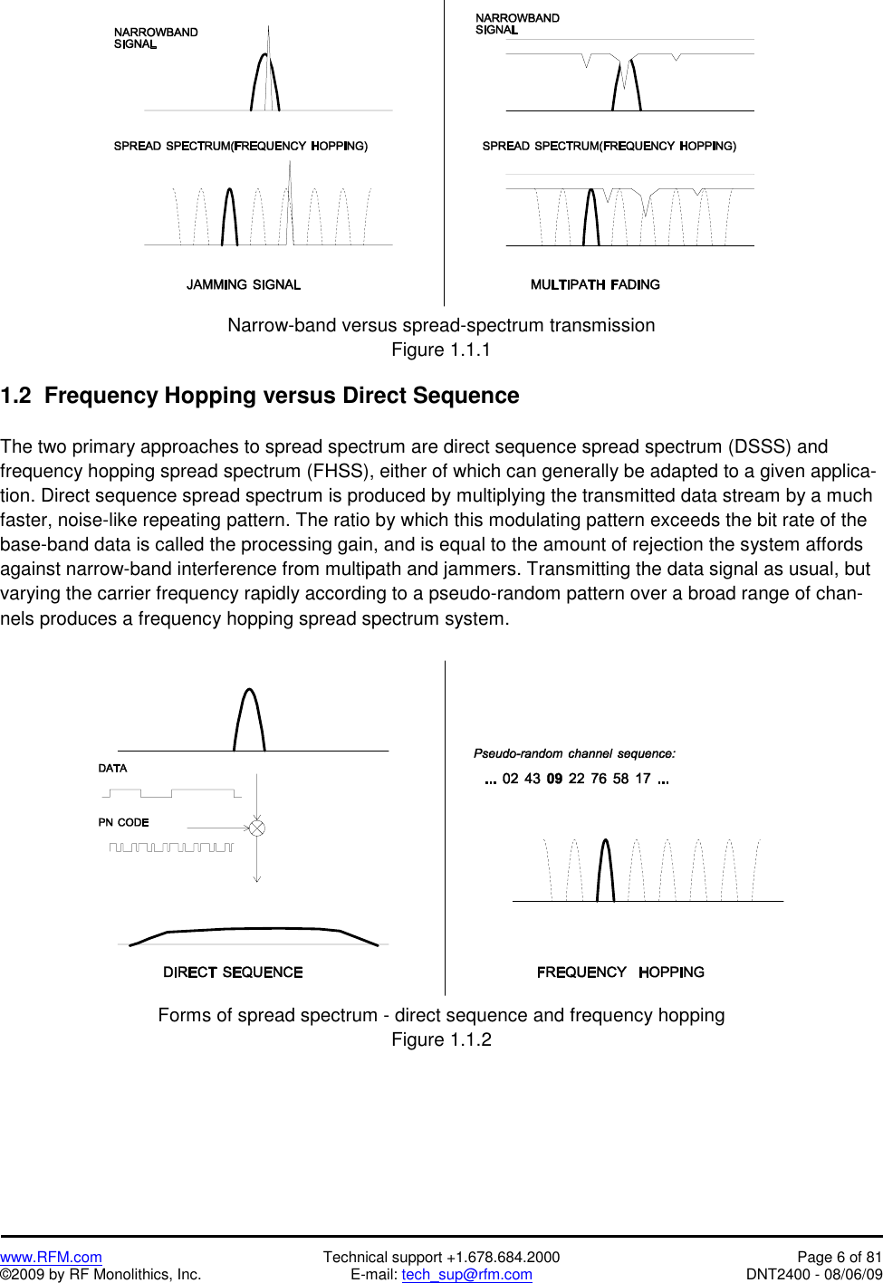
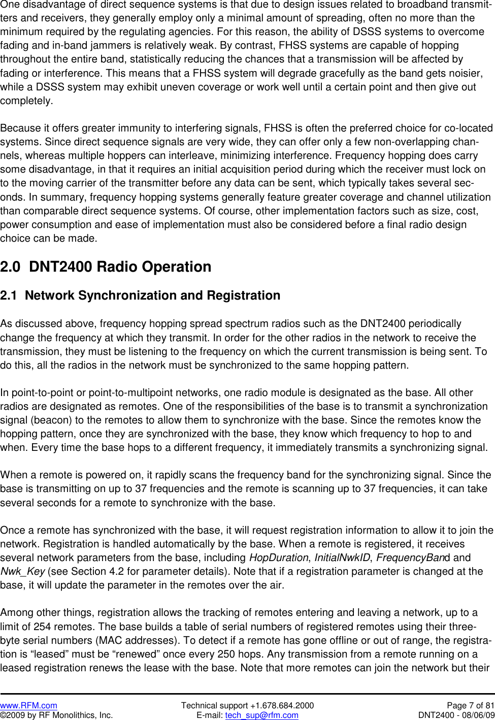
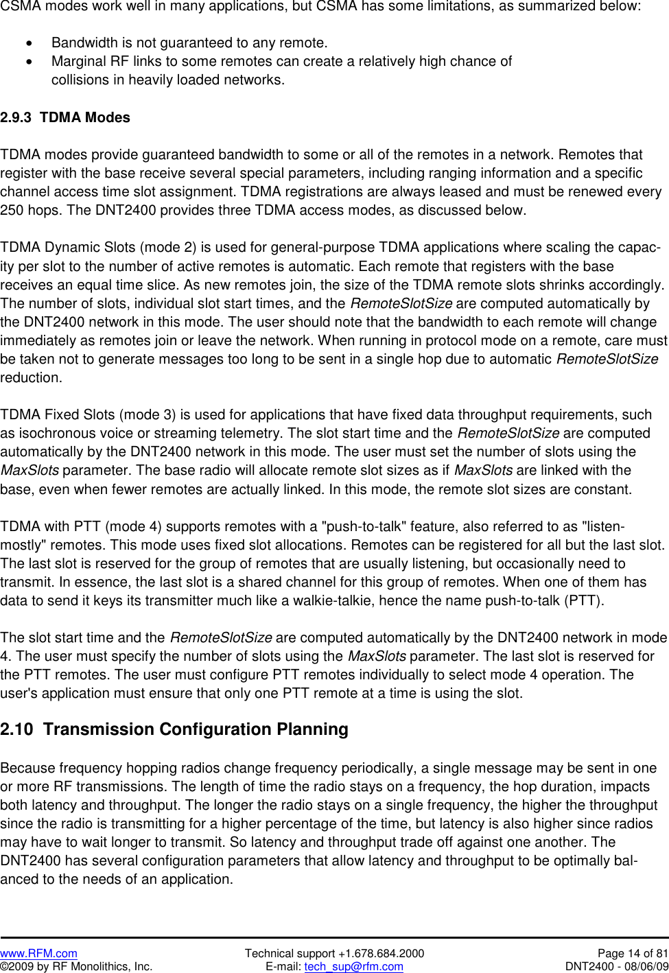
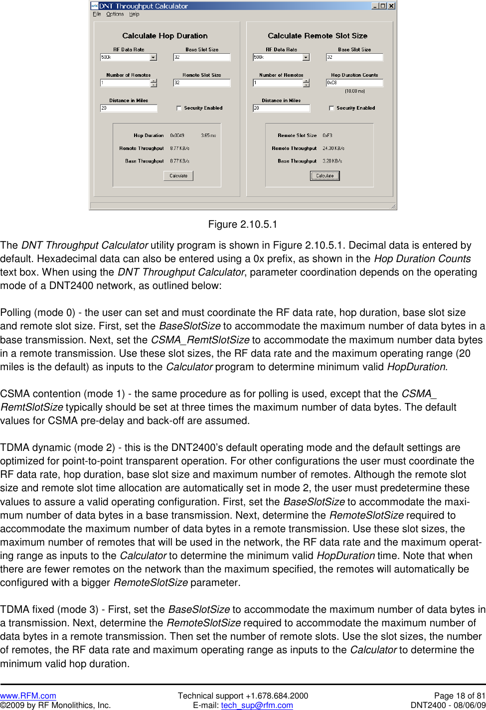
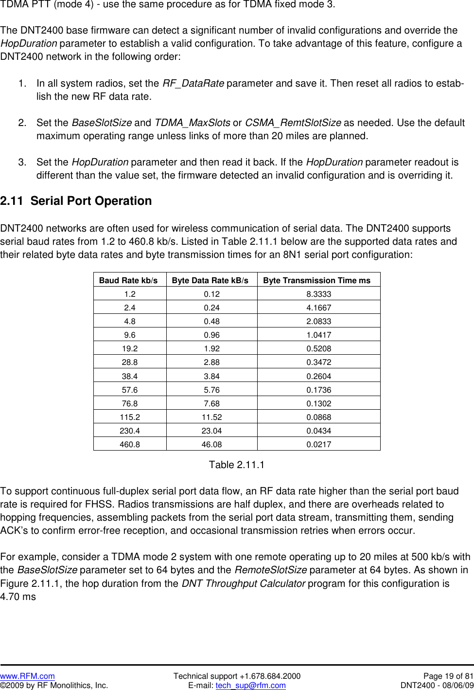
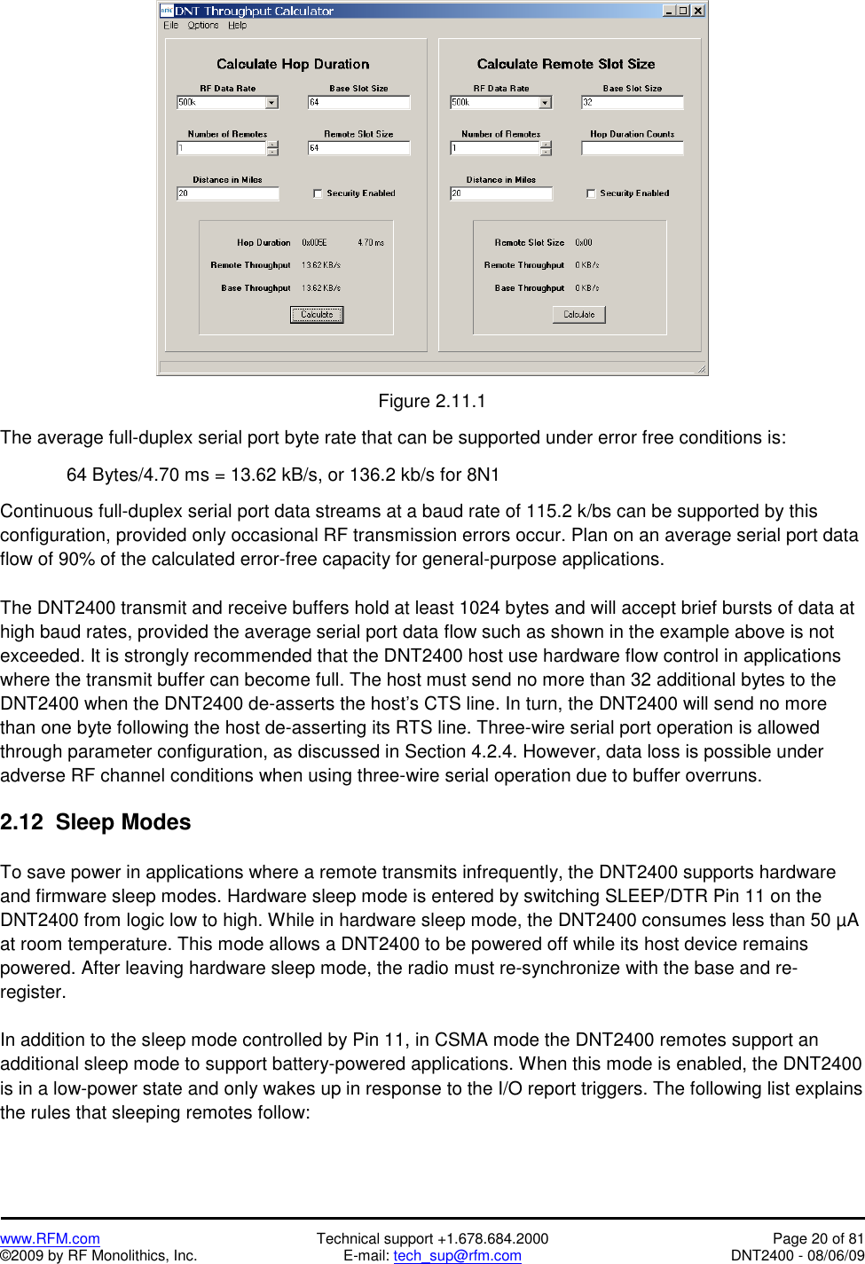
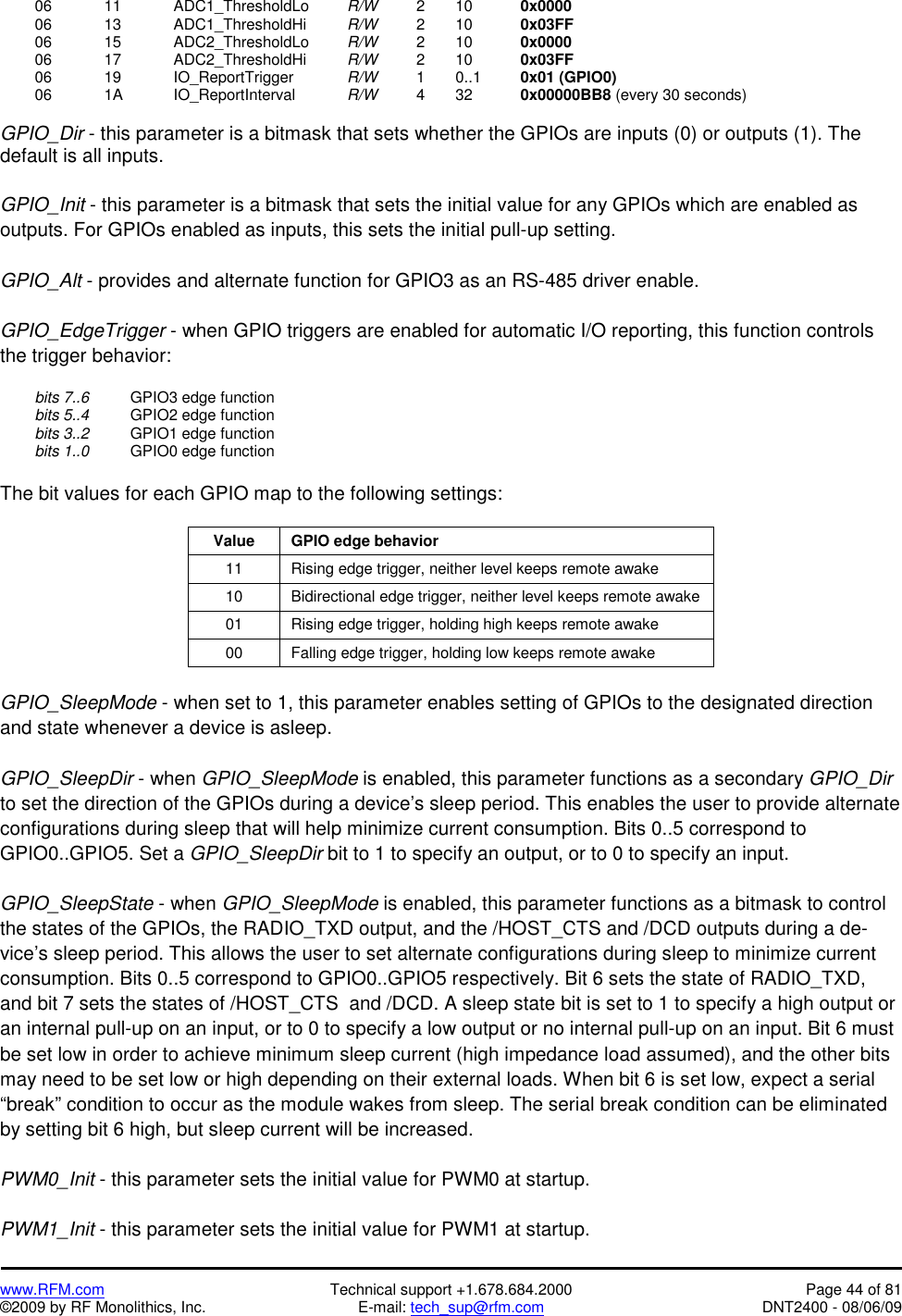
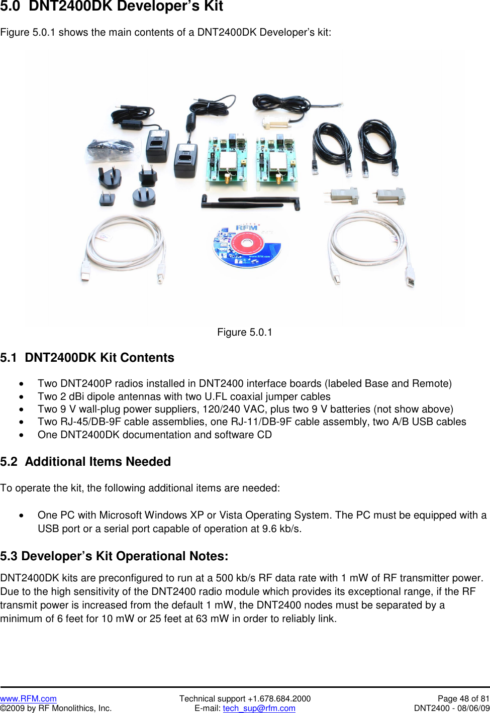
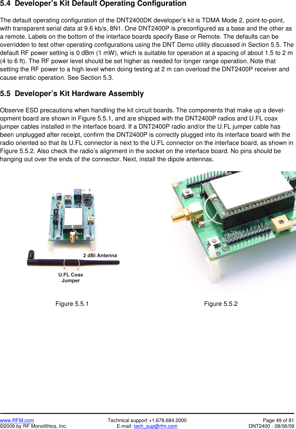
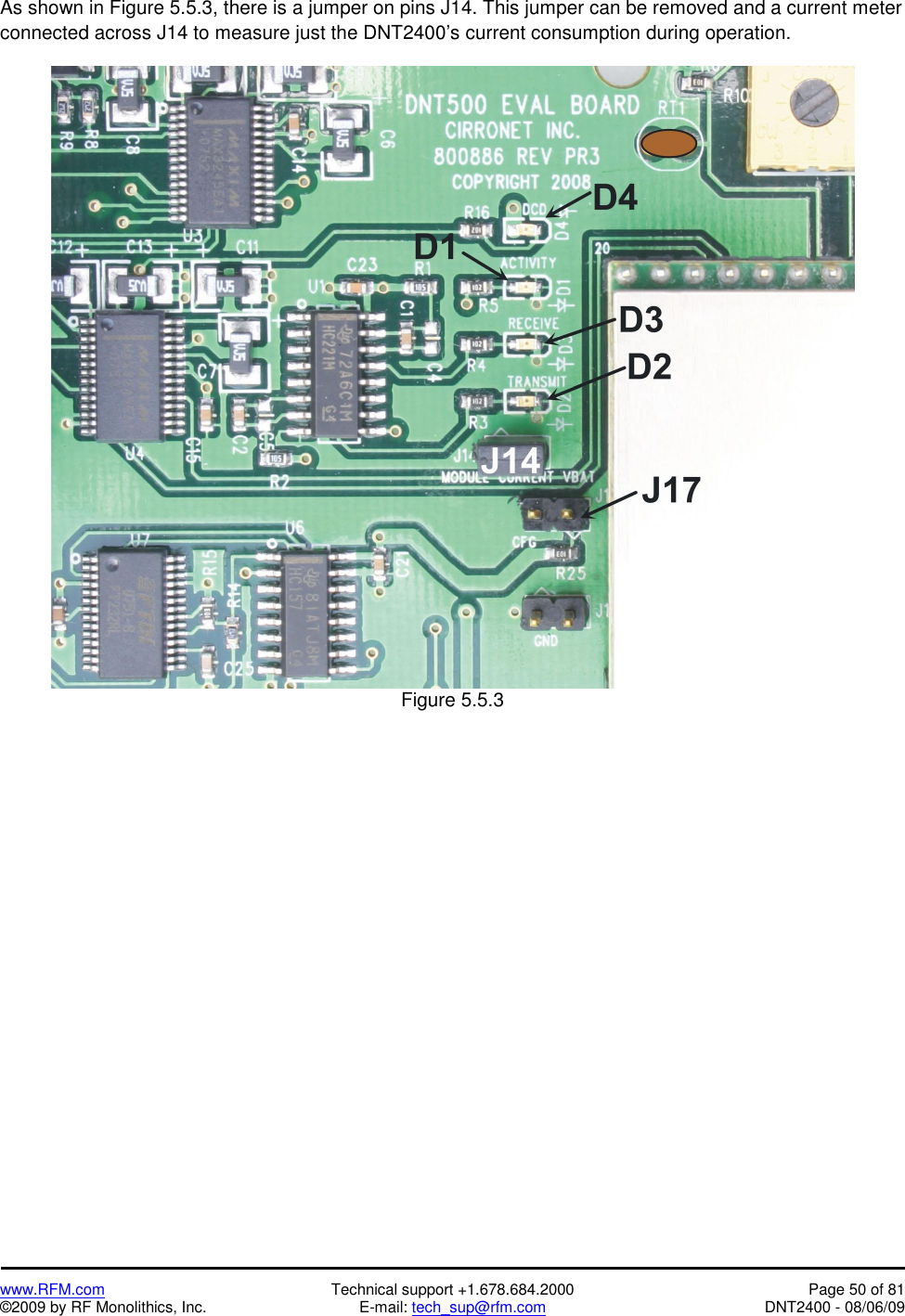
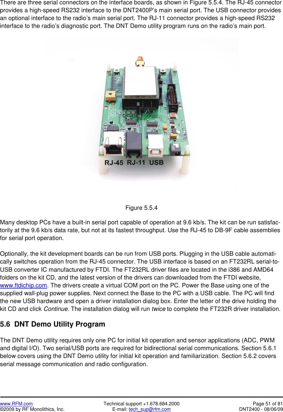
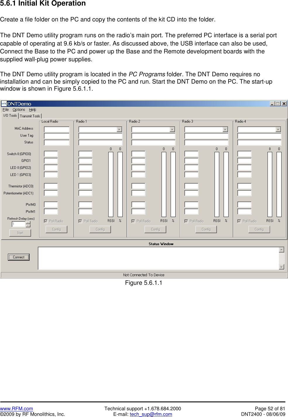
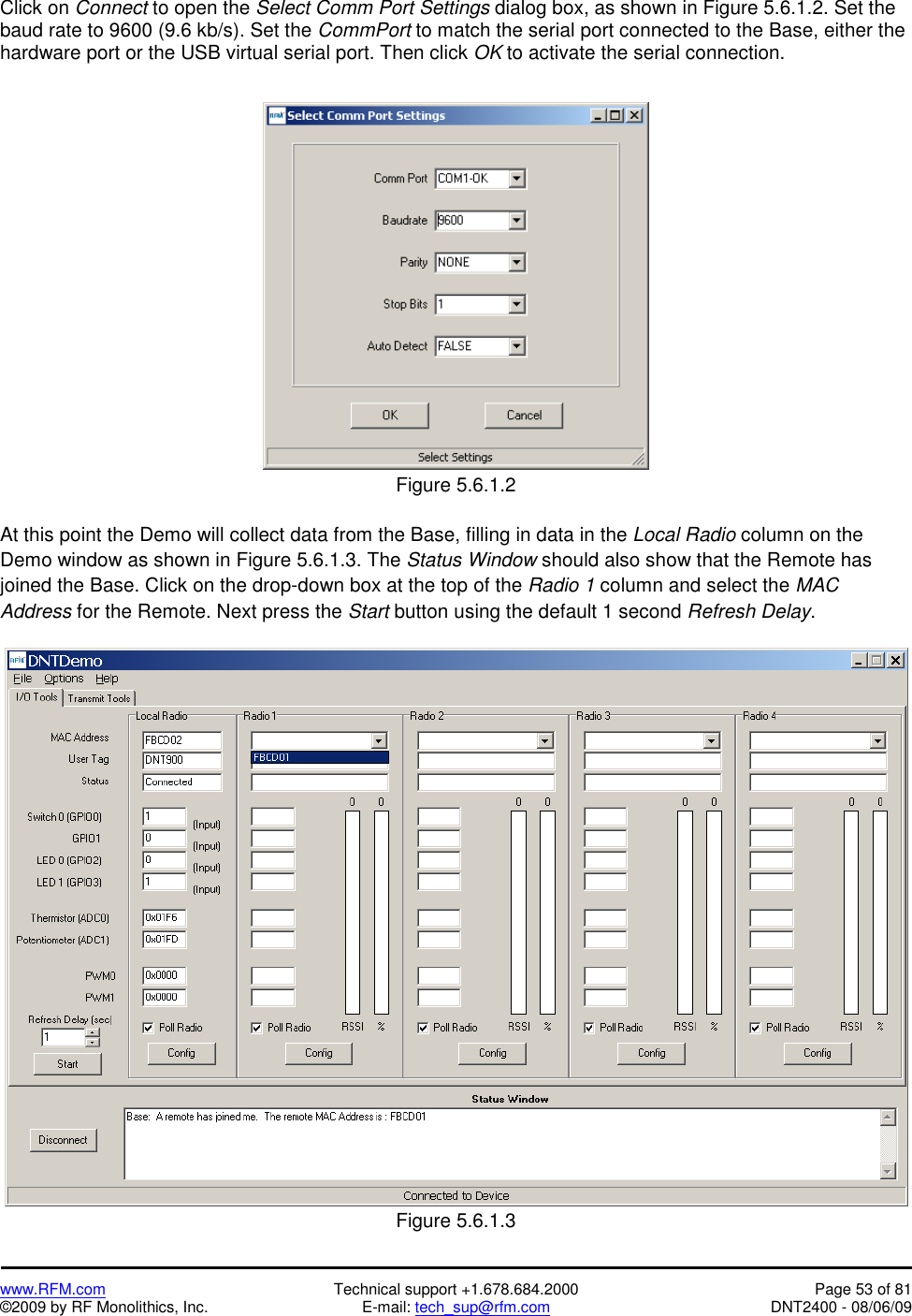
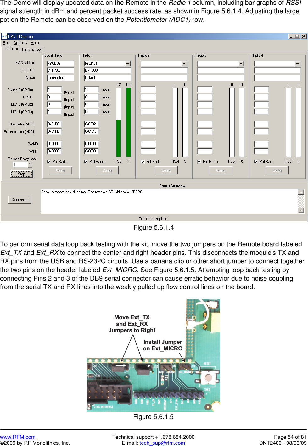
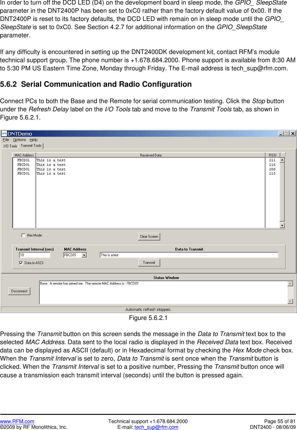
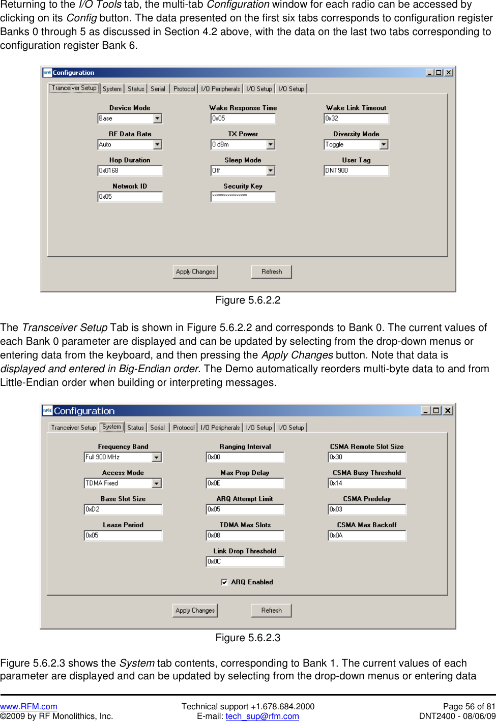
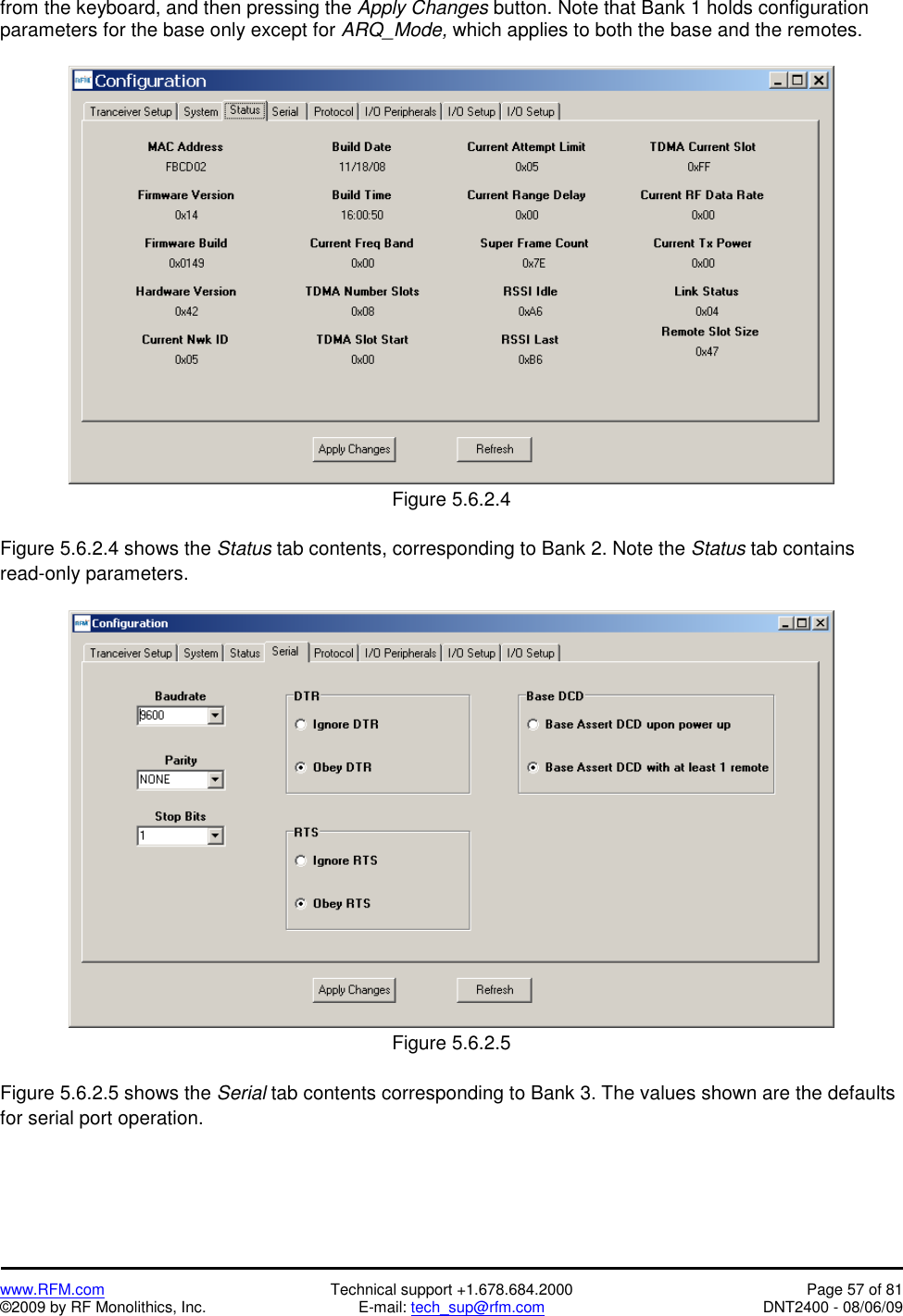
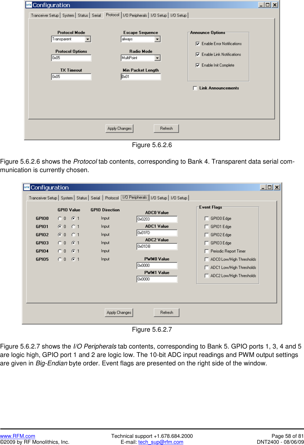
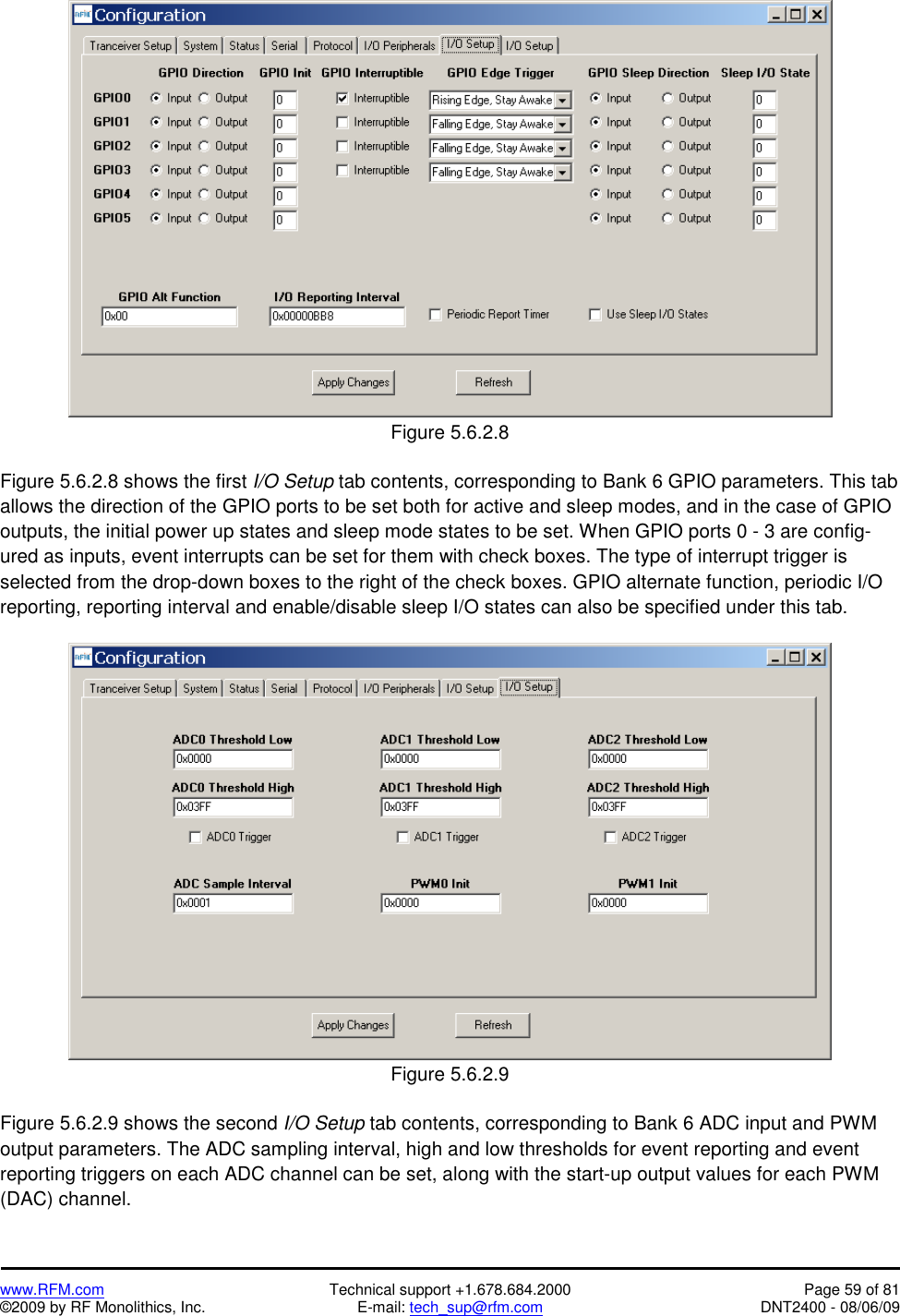
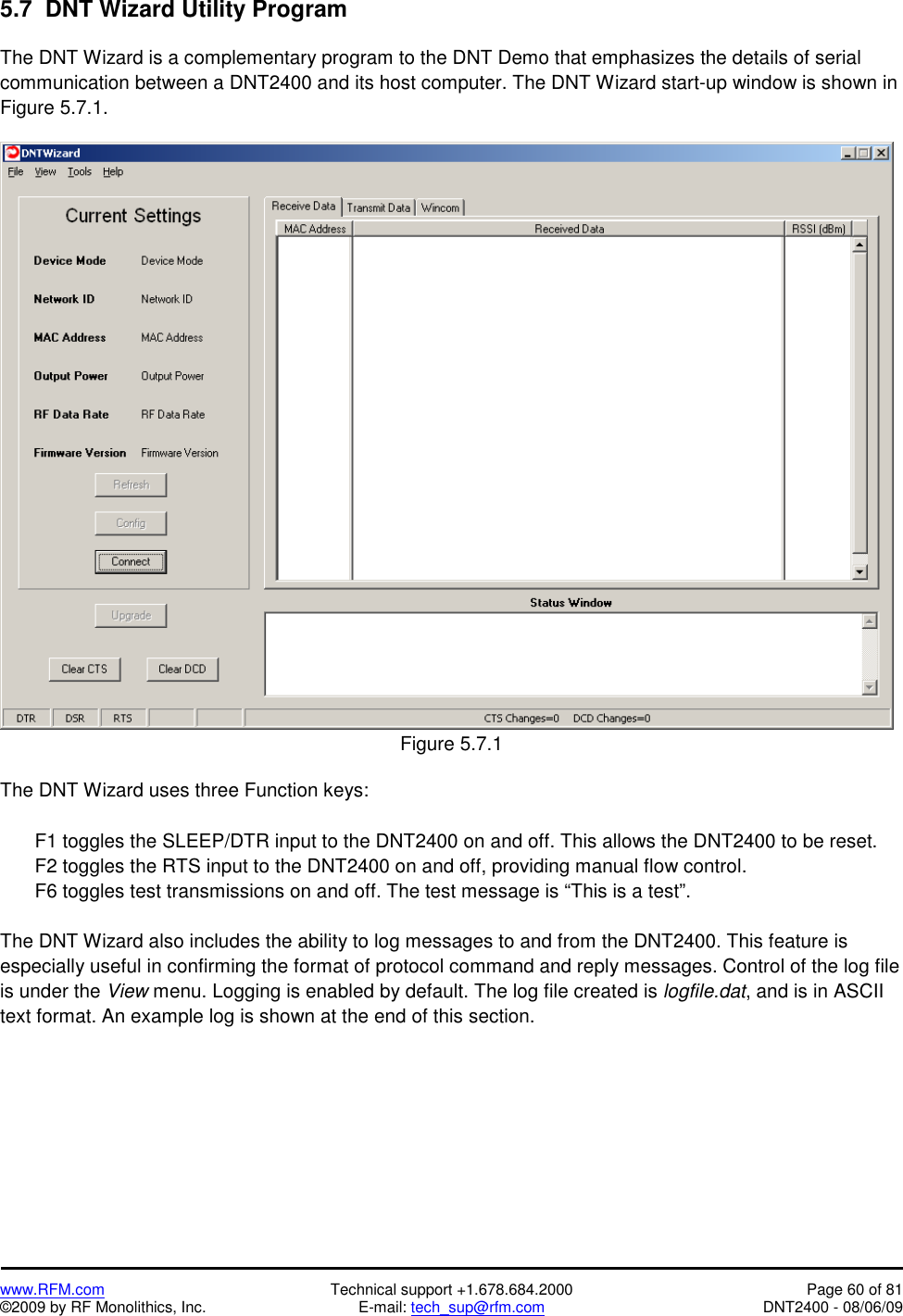
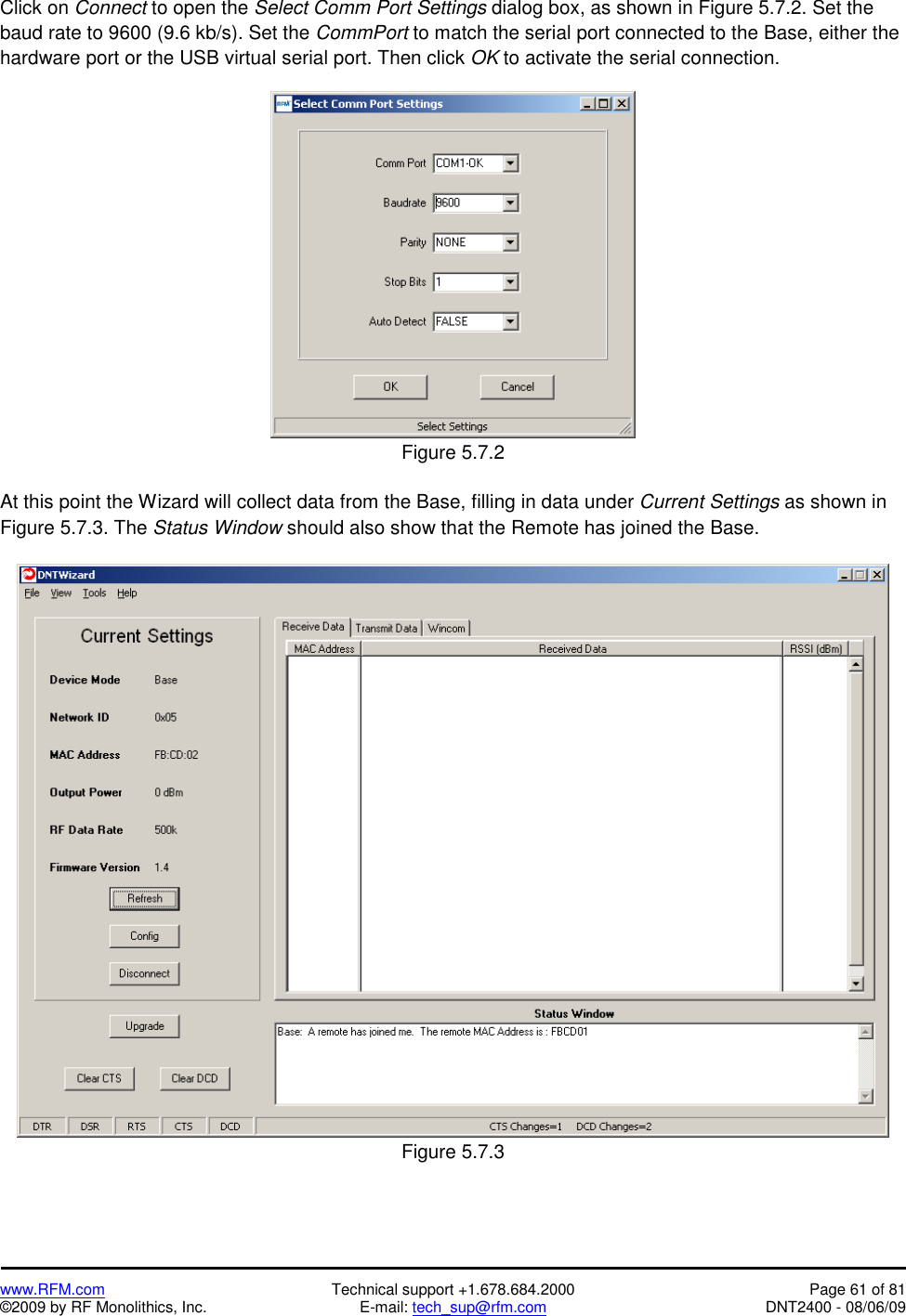
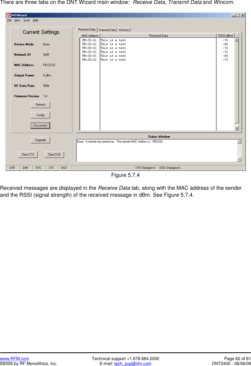
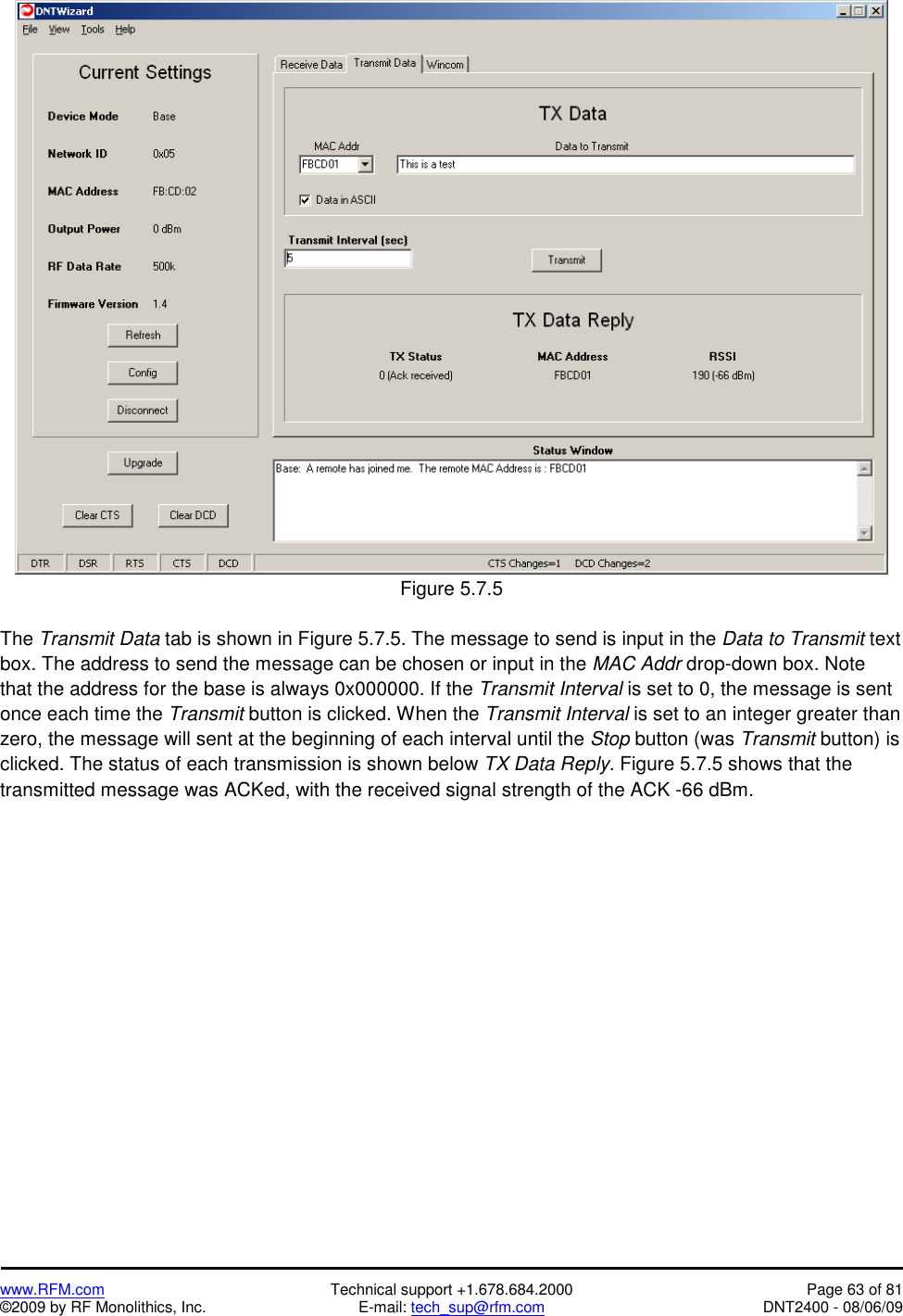
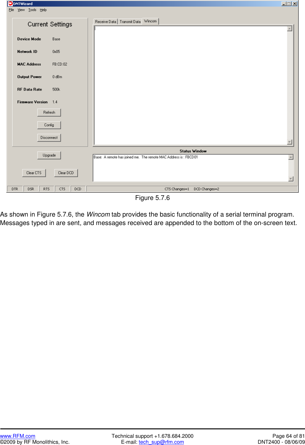
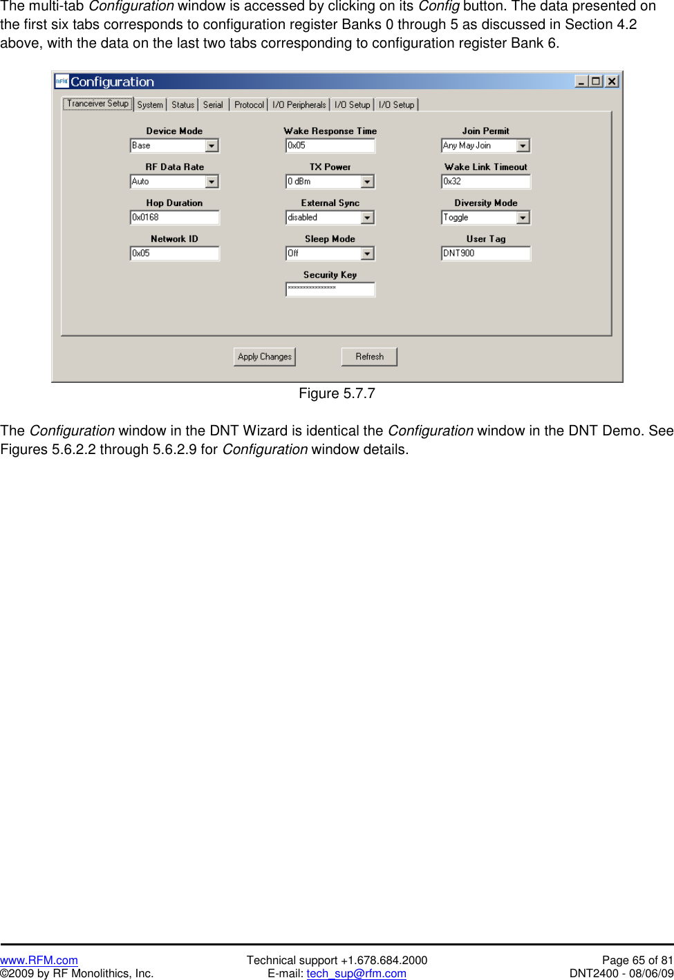
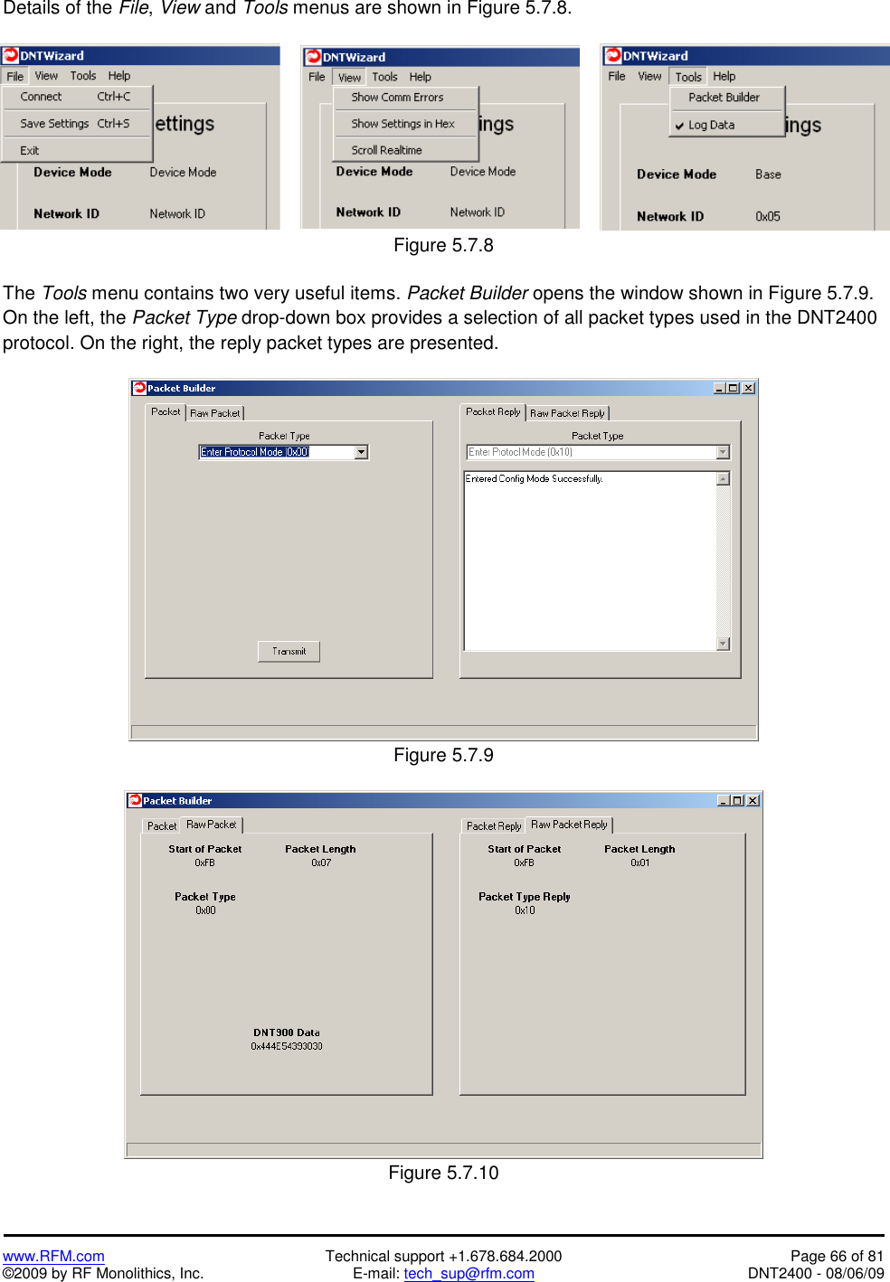
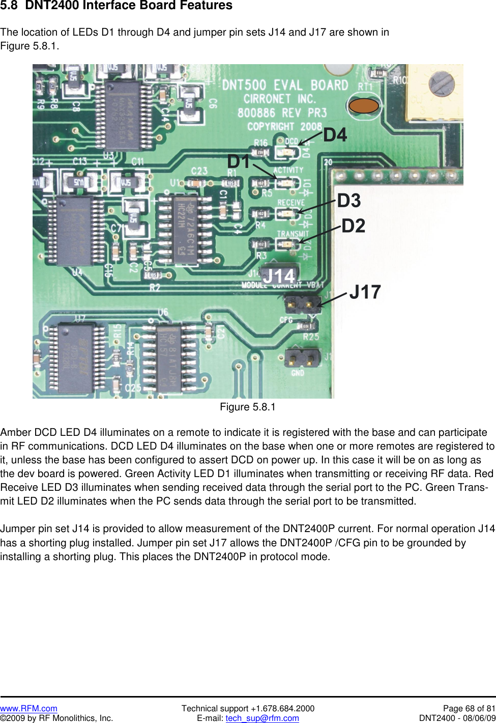
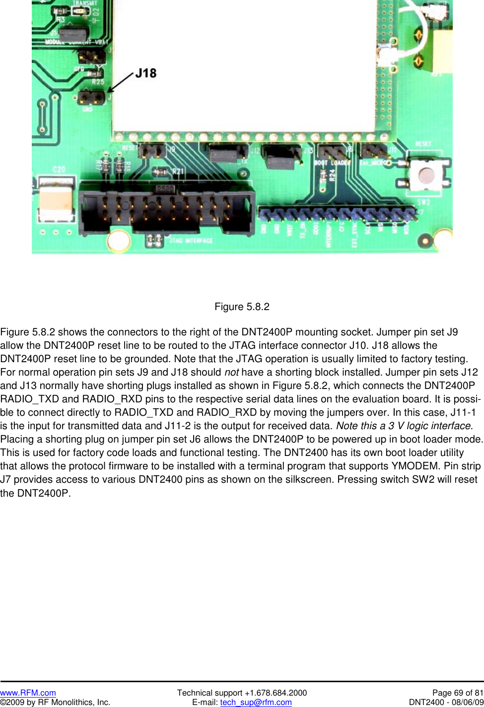
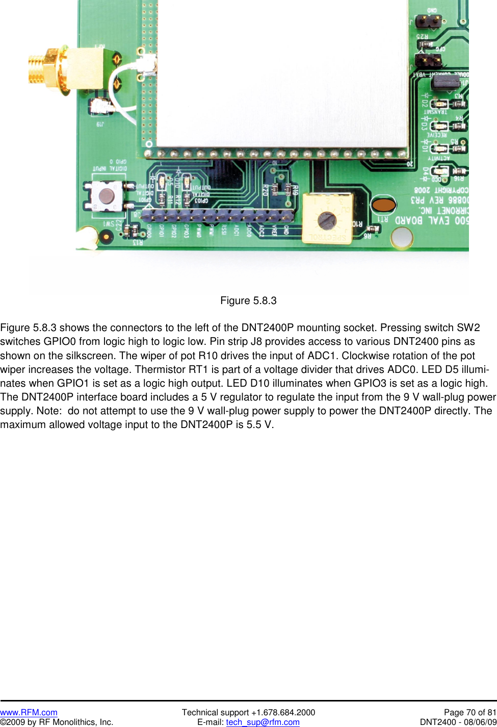
![www.RFM.com Technical support +1.678.684.2000 Page 35 of 81 ©2009 by RF Monolithics, Inc. E-mail: tech_sup@rfm.com DNT2400 - 08/06/09 DeviceMode - selects the operating mode for the radio: remote, base, or PTT remote (listen mostly remote). Note that changing this setting does not take effect immediately. It must be followed by a Mem-orySave command (See Section 4.2.9) and then a hardware reset. RF_DataRate - this sets the over-the-air data rate. DNT2400’s with different RF data rates cannot inter-communicate. The following codes are defined: 0x00 = 500 kb/s (default) 0x01 = 200 kb/s 0x02 = 115.2 kb/s 0x03 = 38.4 kb/s 0xff = auto The auto setting will cause a remote to try all four over-the-air rates when scanning for a network to join. Setting the RF_DataRate to a fixed value on the remotes will allow a network to link much faster than using the auto setting. However, if the base RF_DataRate is changed when the remotes are set to a fixed rate, the network will not link. Note that changing this setting does not take effect immediately. It must be followed by a MemorySave command (See Section 4.2.9) and then a hardware reset. HopDuration - this sets the duration of the hop frame. The duration is set as a 12-bit value, 0.05 ms/count. Changing the hop duration must be followed by a MemorySave command to allow the change to persist through a reset or power cycle. A HopDuration change takes effect immediately. Re-motes will re-link following a HopDuration parameter change. InitialNwkID - selects the initial network ID that the radio will start (if a base) or join (if a remote). A value of 0xFF instructs a remote to operate in 'promiscuous mode' and join any network it finds (if set for a base, this will select the default network ID of 0x00.) The network ID also sets the base frequency at which the hopping pattern starts, as illustrated by the following equation: FrequencyIndex[n] = HoppingPattern[n + NetworkID mod 32] This allows the user to coordinate frequency spacing of co-located networks to maintain a constant sepa-ration as they hop. The InitialNwkID values of co-located networks should be two apart (0, 2, 4 … or 1, 3, 5 …) for best results. SecurityKey - this sets the 128-bit AES encryption key to be used. To protect the key, this is a write-only parameter for the user (always reads back as 0x2A). Refer to the Section 2.13 for further information. SleepMode - this parameter enables sleep mode, which may be used in conjunction with the automatic I/O reporting feature to wake up on specified triggers. Sleep mode is only available for remotes, and the channel access mode for the network must be one of the CSMA modes. WakeResponseTime - this parameter sets the length of time that a remote in sleep mode will wait for a response after sending an I/O report before going back to sleep, from a minimum of 10 ms to a maximum of 2.5 seconds in 10 ms units. This time interval is set to allow the base host application to respond to a remote with a packet before the remote returns to sleep. If this parameter is set to 0, the remote will stay awake indefinitely after sending an I/O report. This allows the application as much time as needs for any initial configuration after which it can cause the remote to re-enter sleep by setting this to the operating value.](https://usermanual.wiki/Murata-Electronics-North-America/DNT2400/User-Guide-1150627-Page-36.png)