Murata Electronics North America DNT2400 2.4GHz Transceiver Module User Manual 09 0199 Exhibit Cover
Murata Electronics North America 2.4GHz Transceiver Module 09 0199 Exhibit Cover
Manual

5015 B.U. Bowman Drive Buford, GA 30518 USA Voice: 770-831-8048 Fax: 770-831-8598
Certification Exhibit
FCC ID: HSW-DNT2400
IC: 4492A-DNT2400
FCC Rule Part: 15.247
IC Radio Standards Specification: RSS-210
ACS Report Number 09-0199-15C
Manufacturer: RFM / Cirronet Inc.
Model(s): DNT2400C, DNT2400P
Manual
www.RFM.com Technical support +1.678.684.2000 Page 1 of 81
©2009 by RF Monolithics, Inc. E-mail: tech_sup@rfm.com DNT2400 - 08/06/09
DNT2400 Series
2.4 GHz Spread Spectrum
Wireless Transceivers
Integration Guide

www.RFM.com Technical support +1.678.684.2000 Page 2 of 81
©2009 by RF Monolithics, Inc. E-mail: tech_sup@rfm.com DNT2400 - 08/06/09
Important Regulatory Information
RFM Product FCC ID: HSW-DNT2400
IC 4492A-DNT2400
Note: This unit has been tested and found to comply with the limits for a Class B digital device, pursuant
to Part 15 of the FCC Rules. These limits are designed to provide reasonable protection against harmful
interference when the equipment is operated in a commercial environment. This equipment generates,
uses, and can radiate radio frequency energy and, if not installed and used in accordance with the in-
struction manual, may cause harmful interference to radio communications. Operation of this equipment
in a residential area is likely to cause harmful interference in which case the user will be required to
correct the interference at their expense.
FCC Antenna Gain Restriction:
The DNT2400 has been designed to operate with any dipole antenna of up to 9 dBi of gain, or any patch
of up to 6 dBi gain.
The antenna(s) used for this transmitter must be installed to provide a separation distance of at least
20 cm from all persons and must not be co-located or operating in conjunction with any other antenna or
transmitter.
IC RSS-210 Detachable Antenna Gain Restriction:
This device has been designed to operate with the antennas listed below, and having a maximum gain of
9 dB. Antennas not included in this list or having a gain greater than 9 dB are strictly prohibited for use
with this device. The required antenna impedance is 50 ohms:
RFM OMNI249 Omnidirectional Dipole Antenna, 9 dB
RFM PA2400 Patch Antenna, 6 dB
To reduce potential radio interference to other users, the antenna type and its gain should be so chosen
that the equivalent isotropically radiated power (e.i.r.p.) is not more than that permitted for successful
communication.
See Section 3.10 of this manual for regulatory notices and labeling requirements. Changes or modifica-
tions to a DNT2400 not expressly approved by RFM may void the user’s authority to operate the module.

www.RFM.com Technical support +1.678.684.2000 Page 3 of 81
©2009 by RF Monolithics, Inc. E-mail: tech_sup@rfm.com DNT2400 - 08/06/09
Table of Contents
1.0 Introduction ......................................................................................................................................... 5
1.1 Why Spread Spectrum?................................................................................................................... 5
1.2 Frequency Hopping versus Direct Sequence..................................................................................6
2.0 DNT2400 Radio Operation ................................................................................................................. 7
2.1 Network Synchronization and Registration...................................................................................... 7
2.2 Authentication .................................................................................................................................. 8
2.3 Transparent and Protocol Serial Port Modes .................................................................................. 9
2.4 RF Data Communications................................................................................................................ 9
2.5 RF Transmission Error Control........................................................................................................ 9
2.6 Transmitter Power Management ................................................................................................... 10
2.7 Network Configurations ................................................................................................................. 10
2.7.1 Point-to-Point Network Operation............................................................................................... 10
2.7.2 Point-to-Multipoint Network Operation ....................................................................................... 11
2.7.3 Peer-to-Peer Network Operation................................................................................................ 11
2.8 Full-Duplex Serial Data Communications...................................................................................... 11
2.9 Channel Access............................................................................................................................. 12
2.9.1 Polling Mode............................................................................................................................... 12
2.9.2 CSMA Mode ............................................................................................................................... 13
2.9.3 TDMA Modes.............................................................................................................................. 14
2.10 Transmission Configuration Planning............................................................................................ 14
2.10.1 TDMA Throughput...................................................................................................................... 15
2.10.2 Polling Throughput ..................................................................................................................... 15
2.10.3 CSMA Throughput...................................................................................................................... 16
2.10.4 Latency ....................................................................................................................................... 16
2.10.5 Configuration Validation ............................................................................................................. 17
2.11 Serial Port Operation .................................................................................................................. 19
2.12 Sleep Modes.................................................................................................................................. 20
2.13 Encryption...................................................................................................................................... 22
2.14 Synchronizing Co-located Bases................................................................................................... 22
3.0 DNT2400 Hardware .......................................................................................................................... 24
3.1 Specifications................................................................................................................................. 25
3.2 Module Interface ............................................................................................................................ 26
3.3 DNT2400C RFIO Stripline ............................................................................................................. 27
3.4 DNT2400 Antenna Connector ....................................................................................................... 28
3.5 Input Voltages................................................................................................................................ 28
3.6 ESD and Transient Protection ....................................................................................................... 28
3.7 Interfacing to 5 V Logic Systems ................................................................................................... 29
3.8 Power-On Reset Requirements..................................................................................................... 29
3.9 Mounting and Enclosures .............................................................................................................. 29
3.10 Labeling and Notices ..................................................................................................................... 29
4.0 Protocol Messages............................................................................................................................ 31
4.1 Protocol Message Formats............................................................................................................ 31
4.1.1 Message Types .......................................................................................................................... 31
4.1.2 Message Format Details............................................................................................................. 32
4.1.3 /CFG Select Pin.......................................................................................................................... 33
4.1.4 Flow Control ............................................................................................................................... 33
4.1.5 Protocol Mode Data Message Example ..................................................................................... 34

www.RFM.com Technical support +1.678.684.2000 Page 4 of 81
©2009 by RF Monolithics, Inc. E-mail: tech_sup@rfm.com DNT2400 - 08/06/09
4.2 Configuration Registers ................................................................................................................. 34
4.2.1 Bank 0 - Transceiver Setup........................................................................................................ 34
4.2.2 Bank 1 - System Settings ........................................................................................................... 36
4.2.3 Bank 2 - Status Registers........................................................................................................... 39
4.2.4 Bank 3 - Serial ............................................................................................................................ 41
4.2.5 Bank 4 - Host Protocol Settings ................................................................................................. 42
4.2.6 Bank 5 - I/O Peripheral Registers............................................................................................... 43
4.2.7 Bank 6 - I/O Setup ...................................................................................................................... 43
4.2.8 Bank 7 - Authentication List........................................................................................................ 45
4.2.9 Bank FF - Special Functions ...................................................................................................... 46
4.2.10 Protocol Mode Configuration Message Example ....................................................................... 46
4.2.11 Protocol Mode Sensor Message Example ................................................................................. 47
4.2.12 Protocol Mode Event Message Example ................................................................................... 47
5.0 DNT2400DK Developer’s Kit ............................................................................................................ 48
5.1 DNT2400DK Kit Contents.............................................................................................................. 48
5.2 Additional Items Needed................................................................................................................ 48
5.3 Developer’s Kit Operational Notes................................................................................................. 48
5.4 Developer’s Kit Default Operating Configuration........................................................................... 49
5.5 Developer’s Kit Hardware Assembly ............................................................................................. 49
5.6 DNT2400 Demo Utility Program .................................................................................................... 51
5.6.1 Initial Kit Operation ..................................................................................................................... 52
5.6.2 Serial Communication and Radio Configuration ........................................................................ 55
5.7 DNT2400 Wizard Utility Program................................................................................................... 60
5.8 DNT2400 Interface Board Features .............................................................................................. 68
6.0 Demonstration Procedure ................................................................................................................. 71
7.0 Troubleshooting ................................................................................................................................ 72
7.1 Diagnostic Port Commands........................................................................................................... 72
8.0 Appendices ....................................................................................................................................... 75
8.1 Ordering Information...................................................................................................................... 75
8.2 Technical Support.......................................................................................................................... 75
8.3 DNT2400 Mechanical Specifications............................................................................................. 76
8.4 DNT2400 Development Board Schematic..................................................................................... 79
9.0 Warranty............................................................................................................................................ 81

www.RFM.com Technical support +1.678.684.2000 Page 5 of 81
©2009 by RF Monolithics, Inc. E-mail: tech_sup@rfm.com DNT2400 - 08/06/09
1.0 Introduction
The DNT2400 series transceivers provide highly reliable wireless connectivity for point-to-point, point-to-
multipoint and peer-to-peer applications. Frequency hopping spread spectrum (FHSS) technology en-
sures maximum resistance to multipath fading and robustness in the presence of interfering signals, while
operation in the 2.4 GHz ISM band allows license-free use world wide. The DNT2400 supports all stan-
dard serial data rates for host communications from 1.2 to 460.8 kb/s. On-board data buffering and an
error correcting radio protocol provide smooth data flow and simplify the task of integration with existing
applications. Key DNT2400 features include:
• Multipath fading resistant frequency hop-
ping technology with up to 37 frequency
channels per subband
• Dynamic TDMA slot assignment that maxi-
mizes throughput and CSMA modes that
maximizes network size
• Support for point-to-point or point-to-
multipoint applications
• AES encryption provides protection from
eavesdropping
• FCC 15.247, IC and ETSI certified for
license-free operation
• Nonvolatile memory stores DNT2400 con-
figuration when powered off
• 10 mile plus range with omnidirectional
antennas (antenna height dependent)
• Selectable 1, 10 and 63 mW transmit power
levels
• Transparent ARQ protocol with data
buffering ensures data integrity
• Selectable RF data rates of 38.4, 155.2, 200
and 500 kb/s
• Analog and digital I/O simplifies wireless
sensing
• Auto-reporting I/O mode simplifies applica-
tion development
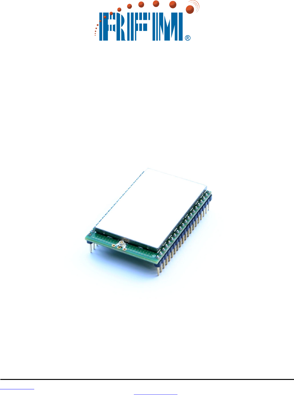
1.1 Why Spread Spectrum?
A radio channel can be very hostile, corrupted by noise, path loss and interfering transmissions from
other radios. Even in an interference-free environment, radio performance faces serious degradation from
a phenomenon known as multipath fading. Multipath fading results when two or more reflected rays of the
transmitted signal arrive at the receiving antenna with opposing phases, thereby partially or completely
canceling the signal. This problem is particularly prevalent in indoor installations. In the frequency do-
main, a multipath fade can be described as a frequency-selective notch that shifts in location and intensity
over time as reflections change due to motion of the radio or objects within its range. At any given time,
multipath fades will typically occupy 1% - 2% of the band. From a probabilistic viewpoint, a conventional
radio system faces a 1% - 2% chance of signal impairment at any given time due to multipath fading.
Spread spectrum reduces the vulnerability of a radio system to both multipath fading and jammers by
distributing the transmitted signal over a larger frequency band than would otherwise be necessary to
send the information. This allows a signal to be reconstructed even though part of it may be lost or cor-
rupted in transmission.
www.RFM.com Technical support +1.678.684.2000 Page 6 of 81
©2009 by RF Monolithics, Inc. E-mail: tech_sup@rfm.com DNT2400 - 08/06/09
Narrow-band versus spread-spectrum transmission
Figure 1.1.1
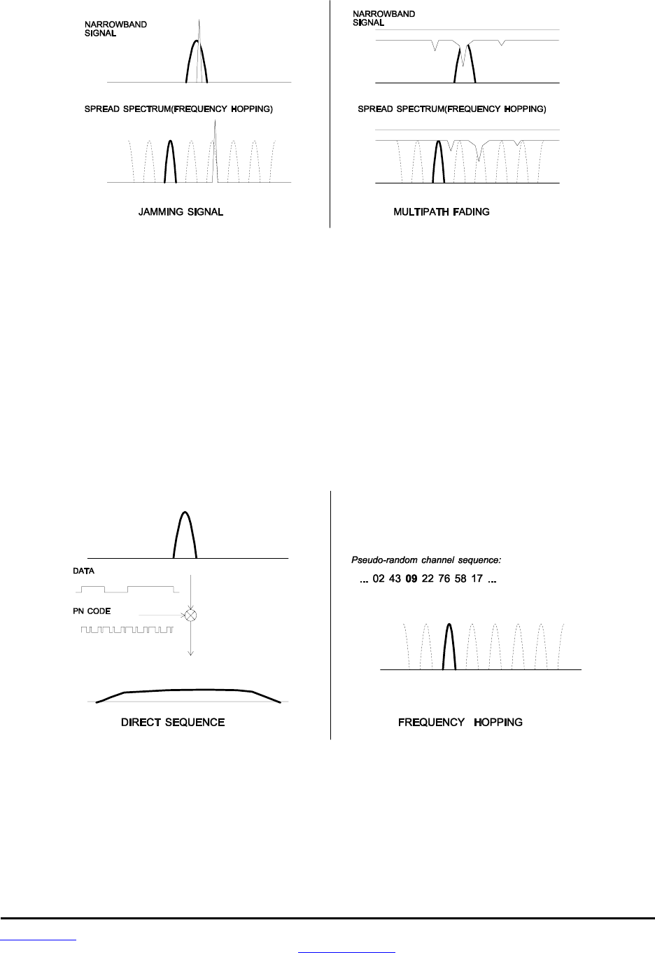
1.2 Frequency Hopping versus Direct Sequence
The two primary approaches to spread spectrum are direct sequence spread spectrum (DSSS) and
frequency hopping spread spectrum (FHSS), either of which can generally be adapted to a given applica-
tion. Direct sequence spread spectrum is produced by multiplying the transmitted data stream by a much
faster, noise-like repeating pattern. The ratio by which this modulating pattern exceeds the bit rate of the
base-band data is called the processing gain, and is equal to the amount of rejection the system affords
against narrow-band interference from multipath and jammers. Transmitting the data signal as usual, but
varying the carrier frequency rapidly according to a pseudo-random pattern over a broad range of chan-
nels produces a frequency hopping spread spectrum system.
Forms of spread spectrum - direct sequence and frequency hopping
Figure 1.1.2

www.RFM.com Technical support +1.678.684.2000 Page 7 of 81
©2009 by RF Monolithics, Inc. E-mail: tech_sup@rfm.com DNT2400 - 08/06/09
One disadvantage of direct sequence systems is that due to design issues related to broadband transmit-
ters and receivers, they generally employ only a minimal amount of spreading, often no more than the
minimum required by the regulating agencies. For this reason, the ability of DSSS systems to overcome
fading and in-band jammers is relatively weak. By contrast, FHSS systems are capable of hopping
throughout the entire band, statistically reducing the chances that a transmission will be affected by
fading or interference. This means that a FHSS system will degrade gracefully as the band gets noisier,
while a DSSS system may exhibit uneven coverage or work well until a certain point and then give out
completely.
Because it offers greater immunity to interfering signals, FHSS is often the preferred choice for co-located
systems. Since direct sequence signals are very wide, they can offer only a few non-overlapping chan-
nels, whereas multiple hoppers can interleave, minimizing interference. Frequency hopping does carry
some disadvantage, in that it requires an initial acquisition period during which the receiver must lock on
to the moving carrier of the transmitter before any data can be sent, which typically takes several sec-
onds. In summary, frequency hopping systems generally feature greater coverage and channel utilization
than comparable direct sequence systems. Of course, other implementation factors such as size, cost,
power consumption and ease of implementation must also be considered before a final radio design
choice can be made.
2.0 DNT2400 Radio Operation
2.1 Network Synchronization and Registration
As discussed above, frequency hopping spread spectrum radios such as the DNT2400 periodically
change the frequency at which they transmit. In order for the other radios in the network to receive the
transmission, they must be listening to the frequency on which the current transmission is being sent. To
do this, all the radios in the network must be synchronized to the same hopping pattern.
In point-to-point or point-to-multipoint networks, one radio module is designated as the base. All other
radios are designated as remotes. One of the responsibilities of the base is to transmit a synchronization
signal (beacon) to the remotes to allow them to synchronize with the base. Since the remotes know the
hopping pattern, once they are synchronized with the base, they know which frequency to hop to and
when. Every time the base hops to a different frequency, it immediately transmits a synchronizing signal.
When a remote is powered on, it rapidly scans the frequency band for the synchronizing signal. Since the
base is transmitting on up to 37 frequencies and the remote is scanning up to 37 frequencies, it can take
several seconds for a remote to synchronize with the base.
Once a remote has synchronized with the base, it will request registration information to allow it to join the
network. Registration is handled automatically by the base. When a remote is registered, it receives
several network parameters from the base, including HopDuration, InitialNwkID, FrequencyBand and
Nwk_Key (see Section 4.2 for parameter details). Note that if a registration parameter is changed at the
base, it will update the parameter in the remotes over the air.
Among other things, registration allows the tracking of remotes entering and leaving a network, up to a
limit of 254 remotes. The base builds a table of serial numbers of registered remotes using their three-
byte serial numbers (MAC addresses). To detect if a remote has gone offline or out of range, the registra-
tion is “leased” must be “renewed” once every 250 hops. Any transmission from a remote running on a
leased registration renews the lease with the base. Note that more remotes can join the network but their

www.RFM.com Technical support +1.678.684.2000 Page 8 of 81
©2009 by RF Monolithics, Inc. E-mail: tech_sup@rfm.com DNT2400 - 08/06/09
entering and leaving the network cannot be tracked by the base radio. The DNT2400 base can be config-
ured to send join announcements to a host application for an unlimited number of remotes. The applica-
tion can then verify the continued presence of remotes in the network through periodic polling of each
remote.
In addition, the DNT2400 supports a RemoteLeave command that allows a host application to cause a
remote to leave the network. This is useful to remove any rogue remotes that may have joined when
authentication is not being used. It is also useful to remove remotes from the network once they have
been serviced by the application. In this manner, the base can use the lease times to keep track of re-
motes that have not yet been serviced thereby allowing networks of more than 254 remotes to be tracked.
The RemoteLeave command includes the amount of time the remote must leave the network which can
be set from 2 seconds to more than 36 hours. In addition, a remote can be told to leave and not rejoin
until it has been power-cycled or reset.
2.2 Authentication
In many applications it is desirable to control which remote devices may join the network. This provides
security from rogue nodes joining the network and simplifies network segregation for co-located networks.
Network registration of remotes is controlled by the AuthMode parameter in the base. The AuthMode
parameter can be set to one of four values, 0..3. The default value is 0, which allows any remote to regis-
ter with a base.
When the AuthMode parameter is set to 1, a remote’s address must be listed in Parameter Bank 7 before
it will be allowed to register with the base. This is referred to as base authentication. Bank 7 must be
preloaded with the addresses of the authorized remotes before using base authentication. If a remote
whose MAC address is not in Bank 7 attempts to join the network the base radio will deny the registration
request. A maximum of 16 remotes can be entered into Bank 7. To support larger networks, mode 2 must
be used.
When the AuthMode parameter is set to 2, the address of a remote attempting to register with the base is
sent to the host for authentication in a JoinRequest message. The host application determines if the
remote should be allowed to register and returns a JoinReply message to the base containing a Permit-
Status parameter that allows or blocks the remote from registering. The host application has 30 seconds
in which to respond, after which time the base denies registration to the remote. Up to 16 join requests
can be pending at any one time. If more than 16 remotes are asking to join, the first 16 will be serviced
and additional remotes will be serviced after the earlier requests are handled. The RegDenialDelay pa-
rameter controls how often a remote will request registration after it has been denied. If it is anticipated
that more than 16 remotes will request registration before the application can service the first 16, this
parameter should be set to the time it will take the application to service four requests as this will speed
the authentication process by freeing the base from issuing multiple denials to the same remotes.
When the AuthMode parameter is set to 3, authentication is locked to the addresses of the remotes
currently registered with the base. Mode 3 is typically used in conjunction with Mode 0 during a commis-
sioning process. AuthMode is set to 0, remotes are turned on and allowed to register with the base, and
AuthMode is then switched to 3 to lock the network membership.

www.RFM.com Technical support +1.678.684.2000 Page 9 of 81
©2009 by RF Monolithics, Inc. E-mail: tech_sup@rfm.com DNT2400 - 08/06/09
2.3 Transparent and Protocol Serial Port Modes
DNT2400 radios can work in two serial port data modes: transparent and packet protocol. Transparent
mode formatting is simply the raw user data. Protocol mode formatting includes a start-of-packet framing
character, length byte, addressing, command bytes, etc. Transparent mode operation is especially useful
in point-to-point systems that act as simple cable replacements. In point-to-multipoint systems where the
base needs to send data specifically to each remote, protocol formatting must be used unless the data
being sent includes addressing information that the devices connected to the remote radios can use to
determine the intended destination of the broadcast data. Protocol formatting is also required for configu-
ration commands and responses, and sensor I/O commands and responses. Protocol mode can be used
at the base radio while transparent mode is used at the remotes. The one caution about protocol mode is
that the length of a protocol mode message cannot exceed the BaseSlotSize or RemoteSlotSize or the
packet will be discarded. Protocol formatting details are covered in Section 4.
The DNT2400 provides two ways to switch between transparent and protocol modes. If /CFG input Pin 18
on the DNT2400 is switched from logic high to low, protocol mode is invoked. Or if the EnterProtocolMode
command is sent, the DNT2400 will switch to the protocol mode. When input Pin 18 is switched from logic
low to high, or an ExitProtocolMode command is sent to the primary serial input, the DNT2400 will switch
to transparent operation. Note that it is possible that part of the EnterProtocolMode command will be sent
over the air as transparent data.
When operating in transparent mode, two configuration parameters control when a DNT2400 radio will
send the data in its transmit buffer. The MinPacketLength parameter sets the minimum number of bytes
that must be present in the transmit buffer to trigger a transmission. The TxTimeout parameter sets the
maximum time data in the transmit buffer will be held before transmitting it, even if the number of data
bytes is less than MinPacketLength. The default value for MinPacketLength parameter is one and the
TxTimeout parameter is zero, so that any bytes that arrive in the DNT2400 transmit buffer will be sent on
the next hop. As discussed in Section 2.7.2, it is useful to set these parameters to values greater than
their defaults in point-to-multipoint systems where some or all the remotes are in transparent mode.
2.4 RF Data Communications
At the beginning of each hop the base transmits a beacon, which always includes a synchronizing signal.
After synchronization is sent, the base will transmit any user data in its transmit buffer, unless in transpar-
ent mode the MinPacketLength and/or TxTimeout parameters have been set above their default values.
The maximum amount of user data bytes that the base can transmit per hop is limited by the BaseSlot-
Size parameter, as discussed in Section 2.7.1. If there is no user data or reception acknowledgements
(ACKs) to be sent on a hop, the base will only transmit the synchronization signal in the beacon.
The operation for remotes is similar to the base, but without a synchronizing signal. The RemoteSlotSize
parameter indicates the maximum number of user data bytes a remote can transmit on one hop and is a
read-only value. The RemoteSlotSize is determined by the HopDuration and BaseSlotSize parameters
and the number of registered remotes. The MinPacketLength and TxTimeout parameters operate in a
remote in the same manner as in the base.
2.5 RF Transmission Error Control
The DNT2400 supports two error control modes: automatic transmission repeats (ARQ), and redundant
transmissions for broadcast packets. In both modes, the radio will detect and discard any duplicates of

www.RFM.com Technical support +1.678.684.2000 Page 10 of 81
©2009 by RF Monolithics, Inc. E-mail: tech_sup@rfm.com DNT2400 - 08/06/09
messages it receives so that the host application will only receive one copy of a given message. In the
redundant transmission mode, broadcast packets are repeated a fixed number of times based on the
value of the ARQ_AttemptLimit parameter. In ARQ mode, a packet is sent and an acknowledgement is
expected on the next hop. If an acknowledgement is not received, the packet is transmitted again on the
next available hop until either an ACK is received or the maximum number of attempts is exhausted. If the
ARQ_AttemptLimit parameter is set to its maximum value, a packet transmission will be retried without
limit until the packet is acknowledged. This is useful in some point-to-point cable replacement applications
where it is important that data truly be 100% error-free, even if the destination remote goes out of range
temporarily.
2.6 Transmitter Power Management
The DNT2400 includes provisions for setting the base transmit power level and the remote maximum
transmit power level with the TxPower parameter. DNT2400 networks covering a small area can be
adjusted to run at lower transmitter power levels, reducing potential interference to other nearby systems
such as 802.11 networks. Remotes that are located close to their base can be adjusted to run at lower
maximum power, further reducing potential interference. Base units transmit at the fixed power level set
by the TxPower parameter. Remotes automatically adjust their transmitter power to deliver packets to the
base at an adequate but not excessive signal level, while not transmitting more power than set by their
TxPower parameter. Remotes make transmitter power adjustments using the strength of the signals
received from the base and the base transmitter power setting, which is periodically transmitted by the
base. The remote automatic transmit power adjustment is enabled by default but can be disabled if so
desired. Refer to Section 4.2.1 for details.
2.7 Network Configurations
The DNT2400 supports three network configurations: point-to-point, point-to-multipoint, and peer-to-peer.
In a point-to-point network, one radio is set up as the base and the other radio is set up as a remote. In a
point-to-multipoint network, a star topology is used with the radio set up as a base acting as the central
communications point and all other radios in the network set up as remotes. In this configuration, each
communication takes place between the base and one of the remotes. Peer-to-peer communications
between remotes using the base as a relay is also supported, as discussed in Section 2.7.3.
2.7.1 Point-to-Point Network Operation
Most point-to-point networks act as serial cable replacements and both the base and the remote use
transparent mode. Unless the MinPacketLength and TxTimeout parameters have been set above their
default values, the base will send the data in its transmit buffer on each hop, up to a limit controlled by the
BaseSlotSize parameter. In transparent mode, if the base is buffering more data than can be sent on one
hop, the remaining data will be sent on subsequent hops. The base adds the address of the remote, a
packet sequence number and error checking bytes to the data when it is transmitted. These additional
bytes are not output at the remote in transparent mode. The sequence number is used in acknowledging
successful transmissions and in retransmitting corrupted transmissions. A two-byte CRC and a one-byte
checksum allow a received transmission to be checked for errors. When a transmission is received by the
remote, it will be acknowledged if it checks error free. If no acknowledgment is received, the base will
retransmit the same data on the next hop. Note that acknowledgements from remotes are suppressed on
broadcast packets from the base.

www.RFM.com Technical support +1.678.684.2000 Page 11 of 81
©2009 by RF Monolithics, Inc. E-mail: tech_sup@rfm.com DNT2400 - 08/06/09
In point-to-point operation, by default a remote will send the data in its transmit buffer on each hop, up to
the limit controlled by its RemoteSlotSize parameter. If desired, the MinPacketLength and TxTimeout
parameters can be set above their default values, which configures the remote to wait until the specified
amount of data is available or the specified delay has expired before transmitting. In transparent mode, if
the remote is buffering more data than can be sent on one hop, it will send the remaining data in subse-
quent hops. The remote adds its own address, a packet sequence number and error checking bytes to
the data when it is transmitted. These additional bytes are not output at the base if the base is in trans-
parent mode. When a transmission is received by the base, it will be acknowledged if it checks error free.
If no acknowledgment is received, the remote will retransmit the same data on the next hop.
2.7.2 Point-to-Multipoint Network Operation
In a point-to-multipoint network, the base is usually configured for protocol formatting, unless the applica-
tions running on each remote can determine the data’s destination from the data itself. Protocol formatting
adds addressing and other overhead bytes to the user data. If the addressed remote is using transparent
formatting, the source (originator) address and the other overhead bytes are removed. If the remote is
using protocol formatting, the source address and the other overhead bytes are output with the user data.
A remote can operate in a point-to-multipoint network using either transparent or protocol formatting, as
the base is the destination by default. In transparent operation, a remote DNT2400 automatically adds
addressing, a packet sequence number and error checking bytes as in a point-to-point network. When the
base receives the transmission, it will format the data to its host according to its formatting configuration.
A remote running in transparent mode in a point-to-multipoint network can have the MinPacketLength and
TxTimeout parameters set to their default values to reduce latency, or above their default values to re-
duce the volume of small packet transmissions.
2.7.3 Peer-to-Peer Network Operation
After a remote has joined the network, it can communicate with another remote through peer-to-peer
messaging, where the base acts as an automatic message relay. In protocol mode, if a remote specifies a
destination address other than the base address, peer-to-peer messaging is enabled. In transparent
mode, the RmtTransDestAddr parameter sets the destination address. Changing RmtTransDestAddr from
the default base address to the address of another remote enables peer-to-peer messaging. The broad-
cast address can also be used as a peer-to-peer destination address. In this case, the message will be
unicast from the remote to the base (using ARQ) and then broadcast by the base (no ARQ). For peer-to-
peer broadcasts, no acknowledgement is sent and no TxDataReply packet is reported to the host.
2.8 Full-Duplex Serial Data Communications
From a host application’s perspective, DNT2400 serial communications appear full duplex. Both the base
host application and each remote host application can send and receive serial data at the same time. At
the radio level, the base and remotes do not actually transmit at the same time. If they did, the transmis-
sions would collide. As discussed earlier, the base transmits a beacon with a synchronization signal at the
beginning of each hop, followed by its user data. After the base transmission, the remotes can transmit.
Each base and remote transmission may contain all or part of a complete message from its host applica-
tion. From an application’s perspective, the radios are communicating in full duplex since the base can
receive data from a remote before it completes the transmission of a message to the remote and vice-
versa.
www.RFM.com Technical support +1.678.684.2000 Page 12 of 81
©2009 by RF Monolithics, Inc. E-mail: tech_sup@rfm.com DNT2400 - 08/06/09
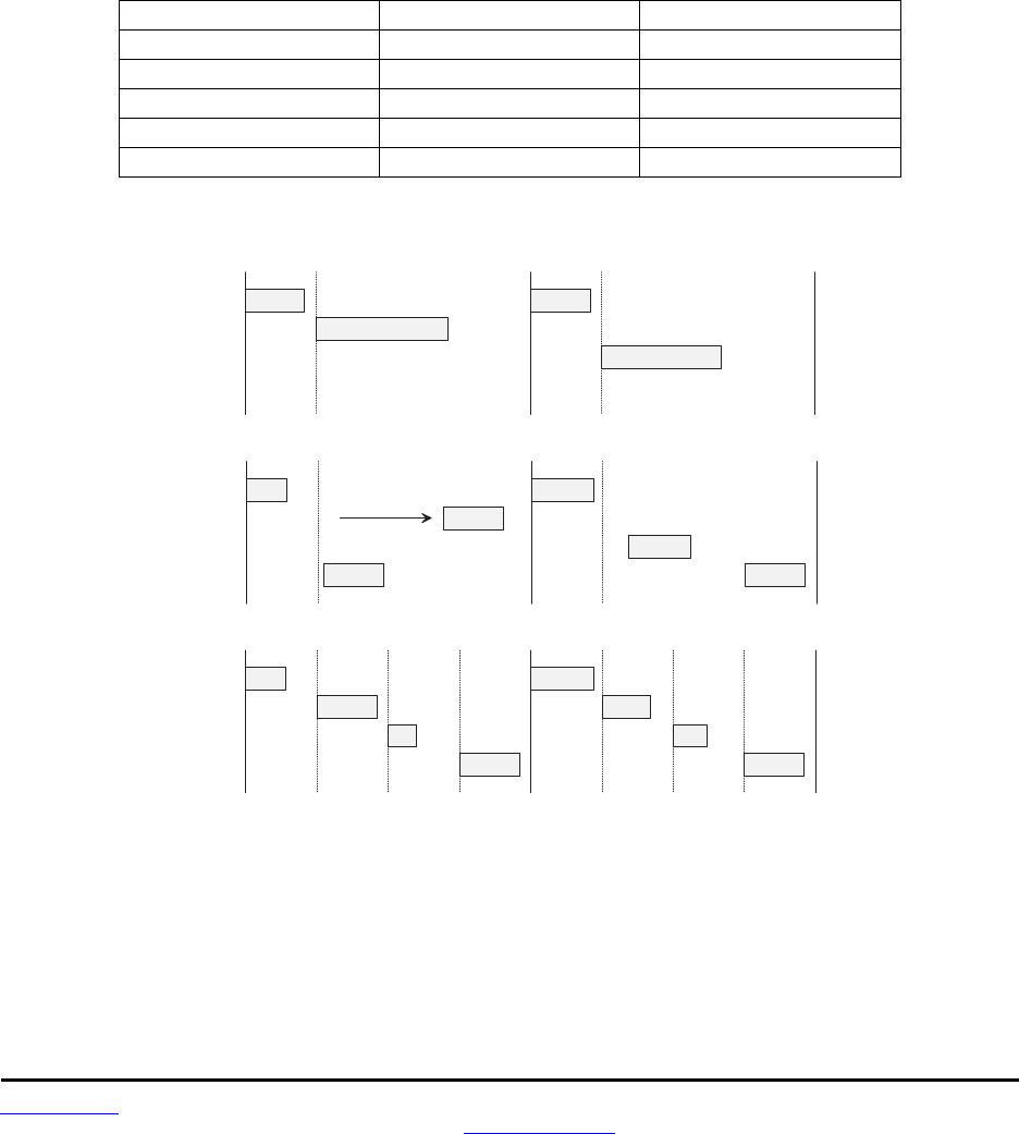
2.9 Channel Access
The DNT2400 provides five methods of channel access: one Polling, two CSMA and three TDMA, as
shown in the table and figure below. The channel access method is selected by the AccessMode parame-
ter in Bank 1. See section 4.2.2. The channel access setting is distributed to all remotes by the base, so
changing it at the base sets the entire network. Polling refers to an application sending a command from
the base to one or more remote devices where only one remote device will respond at a time. Polling is
suitable for both large and small networks where unsolicited or event reporting by remotes is not required.
Carrier Sense Multiple Access (CSMA) is very effective at handling packets with varying amounts of data
and/or packets sent at random times from a large number of remotes. Time Division Multiple Access
(TDMA) provides a scheduled time slot for each remote to transmit on each hop. The default DNT2400
access mode is TDMA dynamic mode.
Access Mode Description Max Number of Remotes
0 Polling unlimited
1 CSMA unlimited
2 TDMA dynamic slots up to 16
3 TDMA fixed slots up to 16
4 TDMA with PTT up to 16
Table 2.9.1
B a s e
R e m o t e # 1
R e m o t e # 2
R e m o t e # 3
T D M A
B a s e
R e m o t e # 1
R e m o t e # 2
R e m o t e # 3
C S M A
XX
B a c k o f f
L i s t e n
L i s t e n
B a s e
R e m o t e # 1
R e m o t e # 2
R e m o t e # 3
P O L L
Figure 2.9.1
2.9.1 Polling Mode
Polling channel access is used for point-to-point and point-to-multipoint systems where only one remote
will attempt to transmit data at a time, usually in response to a command from the base.
Polling (mode 0) is a special case of CSMA mode 1. The user can set the BaseSlotSize and CSMA_
RemtSlotSize parameters when using this mode. Since only one remote will attempt to transmit at a time,

www.RFM.com Technical support +1.678.684.2000 Page 13 of 81
©2009 by RF Monolithics, Inc. E-mail: tech_sup@rfm.com DNT2400 - 08/06/09
to minimize latency, the CSMA_Predelay and CSMA_Backoff parameters are not used. Lease renewals
are also not used, again to minimize latency. Thus, when the base is operated in protocol mode with
Announce messages enabled, only join messages are generated. This mode provides high throughput
since there is no contention between remotes and the entire portion of the hop frame following the base
transmission is available for a remote to transmit. Applications where more than one remote may attempt
to transmit at a time, or where periodic reporting and/or event reporting are enabled should not use this
mode.
2.9.2 CSMA Mode
When using CSMA channel access, each remote with data to send listens to see if the channel is clear
and then transmits. If the channel is not clear, a remote will wait a random period of time and listen again.
CSMA works best when a large or variable number of remotes transmit infrequent bursts of data. There is
no absolute upper limit on the number of remote radios that can be supported in this mode - it depends
on message density. A maximum of 254 remotes can be supported if base join-leave tracking is required,
or an unlimited number of remotes if base join-leave tracking is not required or will be handled by the host
application.
There are two important parameters related to CSMA operation. The CSMA_Backoff parameter defines
the initial time that a remote will wait when it determines the channel is busy before again checking to see
if the channel is clear (back-off interval). If, after finding the channel busy and backing off, the radio finds
the channel busy a second time, the amount of time the remote will wait before checking the channel will
increase. It will continue to increase each subsequent time the channel is busy until the channel is finally
found idle. This is the classic CSMA technique that handles the situation where a number of remotes hold
data to send at the same time. The CSMA_ Predelay parameter controls the maximum time that a remote
will wait before first listening to see if the channel is clear for a transmission. This parameter is used to
make sure that all the remotes do not transmit immediately after the base finishes transmitting.
CSMA (mode 1) provides classical CSMA channel access, and gives the user control over both the
CSMA_Predelay and CSMA_Backoff parameters. This mode is well suited for large numbers of uncoordi-
nated remotes, and/or where periodic/event reporting is used. In addition to CSMA_ Predelay and
CSMA_ MaxBackoff, the user can set the BaseSlotSize and CSMA_RemtSlotSize parameters when
using this mode. The following guidelines are suggested for setting CSMA_Predelay:
• For lightly loaded CSMA contention networks, decrease CSMA_Predelay
to 0x20 or less to reduce latency.
• For heavily loaded CSMA contention networks, increase CSMA_Predelay
to 0x80 or more for better throughput.
As an option, CSMA mode allows the base to directly track remotes entering and leaving the network, for
up to 254 remotes. The base is operated in protocol mode and is configured to send Announce messages
to its host when a remote joins and when the remote’s registration lease expires.
While a base in a CSMA network can track a maximum of 254 remotes entering and leaving the network,
it can generate join Announce messages for an unlimited number of remotes. This allows the host appli-
cation to track remotes entering and leaving a CSMA network with more than 254 remotes by creating its
own table of MAC addresses and periodically sending a GetRemoteRegister command to each remote in
the table. Failure to answer a GetRemoteRegister command indicates the remote is no longer active in
the network.

www.RFM.com Technical support +1.678.684.2000 Page 14 of 81
©2009 by RF Monolithics, Inc. E-mail: tech_sup@rfm.com DNT2400 - 08/06/09
CSMA modes work well in many applications, but CSMA has some limitations, as summarized below:
• Bandwidth is not guaranteed to any remote.
• Marginal RF links to some remotes can create a relatively high chance of
collisions in heavily loaded networks.
2.9.3 TDMA Modes
TDMA modes provide guaranteed bandwidth to some or all of the remotes in a network. Remotes that
register with the base receive several special parameters, including ranging information and a specific
channel access time slot assignment. TDMA registrations are always leased and must be renewed every
250 hops. The DNT2400 provides three TDMA access modes, as discussed below.
TDMA Dynamic Slots (mode 2) is used for general-purpose TDMA applications where scaling the capac-
ity per slot to the number of active remotes is automatic. Each remote that registers with the base
receives an equal time slice. As new remotes join, the size of the TDMA remote slots shrinks accordingly.
The number of slots, individual slot start times, and the RemoteSlotSize are computed automatically by
the DNT2400 network in this mode. The user should note that the bandwidth to each remote will change
immediately as remotes join or leave the network. When running in protocol mode on a remote, care must
be taken not to generate messages too long to be sent in a single hop due to automatic RemoteSlotSize
reduction.
TDMA Fixed Slots (mode 3) is used for applications that have fixed data throughput requirements, such
as isochronous voice or streaming telemetry. The slot start time and the RemoteSlotSize are computed
automatically by the DNT2400 network in this mode. The user must set the number of slots using the
MaxSlots parameter. The base radio will allocate remote slot sizes as if MaxSlots are linked with the
base, even when fewer remotes are actually linked. In this mode, the remote slot sizes are constant.
TDMA with PTT (mode 4) supports remotes with a "push-to-talk" feature, also referred to as "listen-
mostly" remotes. This mode uses fixed slot allocations. Remotes can be registered for all but the last slot.
The last slot is reserved for the group of remotes that are usually listening, but occasionally need to
transmit. In essence, the last slot is a shared channel for this group of remotes. When one of them has
data to send it keys its transmitter much like a walkie-talkie, hence the name push-to-talk (PTT).
The slot start time and the RemoteSlotSize are computed automatically by the DNT2400 network in mode
4. The user must specify the number of slots using the MaxSlots parameter. The last slot is reserved for
the PTT remotes. The user must configure PTT remotes individually to select mode 4 operation. The
user's application must ensure that only one PTT remote at a time is using the slot.
2.10 Transmission Configuration Planning
Because frequency hopping radios change frequency periodically, a single message may be sent in one
or more RF transmissions. The length of time the radio stays on a frequency, the hop duration, impacts
both latency and throughput. The longer the radio stays on a single frequency, the higher the throughput
since the radio is transmitting for a higher percentage of the time, but latency is also higher since radios
may have to wait longer to transmit. So latency and throughput trade off against one another. The
DNT2400 has several configuration parameters that allow latency and throughput to be optimally bal-
anced to the needs of an application.

www.RFM.com Technical support +1.678.684.2000 Page 15 of 81
©2009 by RF Monolithics, Inc. E-mail: tech_sup@rfm.com DNT2400 - 08/06/09
2.10.1 TDMA Throughput
For TDMA channel access, throughput and latency are controlled by the RF data rate, the serial port
baud rate, the BaseSlotSize, the HopDuration, and the number of remotes. A wide range of throughput
and latency combinations can be obtained by adjusting these parameters. The throughput of a radio in a
TDMA network is simply:
Number of bytes per hop/Hop Duration
For the base, the number of byes per hop is controlled by the BaseSlotSize parameter so the throughput
of the base radio is:
BaseSlotSize/HopDuration
Note that if fewer bytes than the BaseSlotSize limit are sent to the base radio by its host during the hop
duration time in transparent mode, the observed throughput of the base radio will be reduced. If the base
is in protocol mode, it will wait until a protocol formatted message is completely received from its host
before transmitting it. If the message is not completely received by the time the base transmits, the base
will wait until the next hop to transmit the message. The throughput for each remote is:
RemoteSlotSize/HopDuration
In a TDMA mode, the RemoteSlotSize is set automatically based on the number of remotes and the
BaseSlotSize. Note that the base radio always reserves BaseSlotSize amount of time in each hop
whether or not the base has user data to send.
To help select appropriate parameter values, RFM provides the DNT2400 Throughput Calculator utility
program. This program is on the development kit CD. Enabling encryption (security) adds additional bytes
to the data to be sent but the Calculator has a mode to take this into account.
2.10.2 Polling Throughput
In polling mode, the application sends data from the base to a specific remote, which causes the remote
and/or its host to send data back to the application. The network operates like a point-to-point network in
this case. In polling, the HopDuration should be set just long enough to accommodate a base transmis-
sion up to the limit allowed by the BaseSlotSize parameter, plus one remote transmission up to the limit
allowed by the CSMA_RemtSlotSize parameter. These slot sizes and the hop duration set the polling
throughput as in TDMA channel access.
The throughput in Polling mode is also determined by the amount of time it takes for the remote host
device to respond to the poll. For example, consider the situation where a remote host device communi-
cates with the DNT2400 at 38.4 kb/s, receives a 16-byte poll command, and takes 1 ms to generate a 32-
byte response which it then sends to the DNT2400. Sixteen bytes over a UART port is 160 bits using
8,N,1 serial parameters. Sending 160 bits at 38.4 kb/s takes 4.2 ms. Add 1 ms for the host device to
process the command and begin sending the 32-byte response. The 32-byte response takes 8.4 ms to
send at 38.4 kb/s, for a total turnaround time of 13.6 ms. This amount of time could be added to the base
and remote slot times to allow the entire transaction to take place in a single hop. However, except at the
38.4 kb/s over-the-air data rate, this is likely to be much longer than the base and remote slot times.
Thus, in practice, lengthening the hop duration to complete the transaction in a single hop doesn’t really
affect the throughput. Nevertheless, it is important to note that the throughput for the remote in the exam-
ple above is substantially less than the remote slot size in bytes divided by the hop duration.

www.RFM.com Technical support +1.678.684.2000 Page 16 of 81
©2009 by RF Monolithics, Inc. E-mail: tech_sup@rfm.com DNT2400 - 08/06/09
It is not a radio requirement that the complete application message be sent in a single hop, nor that the
remote response is returned in a single hop, when in transparent mode. If either transmission occurs over
more than one hop, then depending on the length of the data, the RF data rate and the serial port data
rate at the receiving end, there may be a gap in the serial data. Some protocols, such as Modbus RTU,
use gaps in data to determine packet boundaries.
2.10.3 CSMA Throughput
In CSMA mode, remote radios do not have a fixed throughput, which is why applications requiring guar-
anteed throughput should use polling or a TDMA mode. The reason that the throughput of a CSMA
remote is not fixed is because its ability to transmit at any given time depends on whether another radio is
already transmitting. The throughput of a remote is further affected by how many other remotes are
waiting for the channel to become clear so they can transmit. This is not a problem when remotes, even a
large numbers of remotes, only send data infrequently. The DNT2400 includes several configuration
parameters that can be used to optimize the performance of a CSMA network.
It is often desirable to limit the amount of data a CSMA remote can send in one transmission. This pre-
vents one remote from hogging network throughput. To accommodate this, the DNT2400 provides a
CSMA_RemtSlotSize parameter that is user configurable. When a remote has transmitted CSMA_
RemtSlotSize bytes on a given hop, it will stop transmitting until the next hop. Note that this remote will
have to contend for the channel on the next hop, so it is not guaranteed that it will be the first remote to
transmit on the next hop or that it will be able to transmit on the next hop at all. To allow multiple remotes
a chance to transmit on the same hop, the HopDuration parameter must be set long enough to support
the BaseSlotSize, plus the number of remotes to transmit per hop times CSMA_ RemtSlotSize, plus the
number of remotes to transmit per hop times the CSMA_Backoff. Because of the way CSMA channel
access works, this does not guarantee that the desired number of remotes to transmit on a hop will al-
ways be able to transmit on a single hop. This is due to the fact that when a remote with data to send
finds the channel busy a second time, it waits for a longer period to time before testing the channel again.
This time will continue to increase until the remote finds the channel clear. In practice this is unlikely to
present a problem, as CSMA networks are used with devices that infrequently have data to send.
The DNT2400 Throughput Calculator can be used to determine the HopDuration, but it will be necessary
to increase the number of slots to a value greater than the number of remotes to transmit on a single hop
to account for the backoffs. It is indeterminate how many backoffs may occur during a single hop, which is
why the number of remotes that transmit on a given hop cannot be guaranteed. Note that the CSMA_
Backoff parameter sets the length of time a remote will wait to recheck the channel when it has detected
that the channel is busy. The second time a remote detects that the channel is busy, it will increase the
amount of time it waits until it checks again. Every subsequent time it detects a busy channel it will in-
crease the amount of time it will wait in a geometric fashion. This continues until it detects an idle chan-
nel. So while a short CSMA_Backoff can decrease the time between when one remote transmits and the
next remote transmits, it can actually lead to a longer time between remote transmissions than a longer
backoff. This can occur when the remote checks the channel multiple times during the transmitting re-
mote’s transmission causing the back-off time to be increased.
2.10.4 Latency
The worst case latency for TDMA access, excluding retries, occurs when the radio receives data just after
its turn to transmit. In this instance, it will have to wait the length of time set by the HopDuration to begin

www.RFM.com Technical support +1.678.684.2000 Page 17 of 81
©2009 by RF Monolithics, Inc. E-mail: tech_sup@rfm.com DNT2400 - 08/06/09
transmitting the data. If the radio is receiving data over its serial port at a rate higher than its throughput,
this will only occur at the beginning of a transmission that spans several hops.
In a polling application, latency is affected by how long the remote and/or its host takes to respond, and
when in the hop data is ready to be transmitted. Since a remote can begin transmitting at practically any
time during the hop after the base has transmitted, the latency can be less than HopDuration. However,
the remote transmission may extend over two hops if it starts late in the first hop.
Latency for any given remote in a CSMA network is particularly difficult to characterize. If many remotes
have data to send, the latency for the last remote to send will be the length of time it takes all the other
remotes to send. The CSMA scheme used in the DNT2400 is designed to allow each remote an equal
opportunity to transmit, so the concern is not that one remote is locked out, but just how long it will take a
number of remotes with data to sent to each gain access to the channel and send their data. The more
data that needs to be sent, the more time will be consumed checking the channel and backing off when
the channel is busy. Again, this is why CSMA networks are best used when there are a large number of
nodes that send data infrequently.
The other factor impacting latency is retries. This impact is not unique to frequency hopping radios but is
common among all wireless technologies. A radio only transmits data once per hop. It needs to wait until
the next hop to see if the transmission was received at the destination. If not, the radio will transmit the
data again and wait for the acknowledgement. This can happen up to ARQAttemptLimit number of times
which is equal to ARQAttemptLimit times HopDuration amount of time.
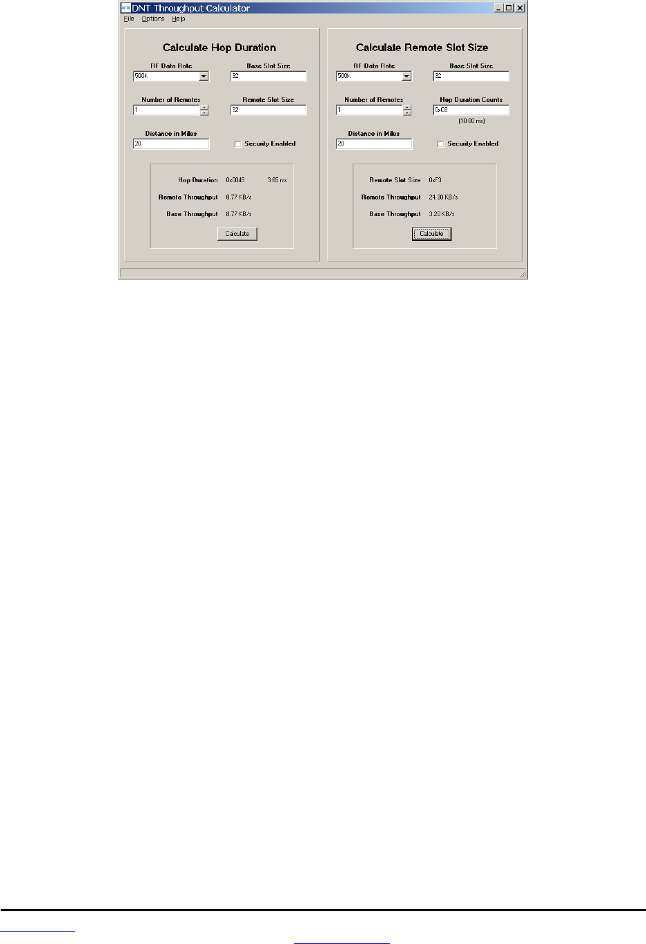
2.10.5 Configuration Validation
Although slot durations are automatically calculated by the DNT2400, the RF data rate, hop duration, etc.,
must be coordinated by the user to assure a valid operating configuration based on the following criteria:
1. Regardless of the RF data rate, the maximum DNT2400 hop duration is limited to 200 ms. A
DNT2400 network must be configured accordingly.
2. In protocol mode, the BaseSlotSize and RemoteSlotSize parameters must be large enough to
hold all the data bytes in the largest protocol formatted message being used. Protocol formatted
messages must be sent in a single transmission. Any protocol formatted messages too large for
the slot size setting will be discarded
3. In TDMA mode 2, the RemoteSlotSize may be reduced automatically when a new remote joins
the network. This can cause a network to suddenly malfunction if the hop duration is not set to
provide an adequately large remote slot allocation when fully loaded with remotes
4. When operating in polling mode 0, the CSMA_RemtSlotSize and HopDuration parameters are
usually set to accommodate the number of data bytes in a maximum size transmission. This con-
figuration provides low latency for polled messages.
5. When operating in CSMA mode 1, the CSMA_RemtSlotSize and HopDuration parameters are
usually set to accommodate three times the number of data bytes in one maximum size transmis-
sion, to allow time for more than one remote to attempt to transmit during a single hop.
www.RFM.com Technical support +1.678.684.2000 Page 18 of 81
©2009 by RF Monolithics, Inc. E-mail: tech_sup@rfm.com DNT2400 - 08/06/09
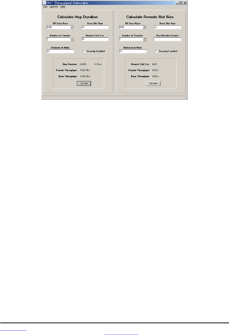
Figure 2.10.5.1
The DNT Throughput Calculator utility program is shown in Figure 2.10.5.1. Decimal data is entered by
default. Hexadecimal data can also be entered using a 0x prefix, as shown in the Hop Duration Counts
text box. When using the DNT Throughput Calculator, parameter coordination depends on the operating
mode of a DNT2400 network, as outlined below:
Polling (mode 0) - the user can set and must coordinate the RF data rate, hop duration, base slot size
and remote slot size. First, set the BaseSlotSize to accommodate the maximum number of data bytes in a
base transmission. Next, set the CSMA_RemtSlotSize to accommodate the maximum number data bytes
in a remote transmission. Use these slot sizes, the RF data rate and the maximum operating range (20
miles is the default) as inputs to the Calculator program to determine minimum valid HopDuration.
CSMA contention (mode 1) - the same procedure as for polling is used, except that the CSMA_
RemtSlotSize typically should be set at three times the maximum number of data bytes. The default
values for CSMA pre-delay and back-off are assumed.
TDMA dynamic (mode 2) - this is the DNT2400’s default operating mode and the default settings are
optimized for point-to-point transparent operation. For other configurations the user must coordinate the
RF data rate, hop duration, base slot size and maximum number of remotes. Although the remote slot
size and remote slot time allocation are automatically set in mode 2, the user must predetermine these
values to assure a valid operating configuration. First, set the BaseSlotSize to accommodate the maxi-
mum number of data bytes in a base transmission. Next, determine the RemoteSlotSize required to
accommodate the maximum number of data bytes in a remote transmission. Use these slot sizes, the
maximum number of remotes that will be used in the network, the RF data rate and the maximum operat-
ing range as inputs to the Calculator to determine the minimum valid HopDuration time. Note that when
there are fewer remotes on the network than the maximum specified, the remotes will automatically be
configured with a bigger RemoteSlotSize parameter.
TDMA fixed (mode 3) - First, set the BaseSlotSize to accommodate the maximum number of data bytes in
a transmission. Next, determine the RemoteSlotSize required to accommodate the maximum number of
data bytes in a remote transmission. Then set the number of remote slots. Use the slot sizes, the number
of remotes, the RF data rate and maximum operating range as inputs to the Calculator to determine the
minimum valid hop duration.

www.RFM.com Technical support +1.678.684.2000 Page 19 of 81
©2009 by RF Monolithics, Inc. E-mail: tech_sup@rfm.com DNT2400 - 08/06/09
TDMA PTT (mode 4) - use the same procedure as for TDMA fixed mode 3.
The DNT2400 base firmware can detect a significant number of invalid configurations and override the
HopDuration parameter to establish a valid configuration. To take advantage of this feature, configure a
DNT2400 network in the following order:
1. In all system radios, set the RF_DataRate parameter and save it. Then reset all radios to estab-
lish the new RF data rate.
2. Set the BaseSlotSize and TDMA_MaxSlots or CSMA_RemtSlotSize as needed. Use the default
maximum operating range unless links of more than 20 miles are planned.
3. Set the HopDuration parameter and then read it back. If the HopDuration parameter readout is
different than the value set, the firmware detected an invalid configuration and is overriding it.
2.11 Serial Port Operation
DNT2400 networks are often used for wireless communication of serial data. The DNT2400 supports
serial baud rates from 1.2 to 460.8 kb/s. Listed in Table 2.11.1 below are the supported data rates and
their related byte data rates and byte transmission times for an 8N1 serial port configuration:
Baud Rate kb/s Byte Data Rate kB/s Byte Transmission Time ms
1.2 0.12 8.3333
2.4 0.24 4.1667
4.8 0.48 2.0833
9.6 0.96 1.0417
19.2 1.92 0.5208
28.8 2.88 0.3472
38.4 3.84 0.2604
57.6 5.76 0.1736
76.8 7.68 0.1302
115.2 11.52 0.0868
230.4 23.04 0.0434
460.8 46.08 0.0217
Table 2.11.1
To support continuous full-duplex serial port data flow, an RF data rate higher than the serial port baud
rate is required for FHSS. Radios transmissions are half duplex, and there are overheads related to
hopping frequencies, assembling packets from the serial port data stream, transmitting them, sending
ACK’s to confirm error-free reception, and occasional transmission retries when errors occur.
For example, consider a TDMA mode 2 system with one remote operating up to 20 miles at 500 kb/s with
the BaseSlotSize parameter set to 64 bytes and the RemoteSlotSize parameter at 64 bytes. As shown in
Figure 2.11.1, the hop duration from the DNT Throughput Calculator program for this configuration is
4.70 ms
www.RFM.com Technical support +1.678.684.2000 Page 20 of 81
©2009 by RF Monolithics, Inc. E-mail: tech_sup@rfm.com DNT2400 - 08/06/09
Figure 2.11.1
The average full-duplex serial port byte rate that can be supported under error free conditions is:
64 Bytes/4.70 ms = 13.62 kB/s, or 136.2 kb/s for 8N1
Continuous full-duplex serial port data streams at a baud rate of 115.2 k/bs can be supported by this
configuration, provided only occasional RF transmission errors occur. Plan on an average serial port data
flow of 90% of the calculated error-free capacity for general-purpose applications.
The DNT2400 transmit and receive buffers hold at least 1024 bytes and will accept brief bursts of data at
high baud rates, provided the average serial port data flow such as shown in the example above is not
exceeded. It is strongly recommended that the DNT2400 host use hardware flow control in applications
where the transmit buffer can become full. The host must send no more than 32 additional bytes to the
DNT2400 when the DNT2400 de-asserts the host’s CTS line. In turn, the DNT2400 will send no more
than one byte following the host de-asserting its RTS line. Three-wire serial port operation is allowed
through parameter configuration, as discussed in Section 4.2.4. However, data loss is possible under
adverse RF channel conditions when using three-wire serial operation due to buffer overruns.
2.12 Sleep Modes
To save power in applications where a remote transmits infrequently, the DNT2400 supports hardware
and firmware sleep modes. Hardware sleep mode is entered by switching SLEEP/DTR Pin 11 on the
DNT2400 from logic low to high. While in hardware sleep mode, the DNT2400 consumes less than 50 µA
at room temperature. This mode allows a DNT2400 to be powered off while its host device remains
powered. After leaving hardware sleep mode, the radio must re-synchronize with the base and re-
register.
In addition to the sleep mode controlled by Pin 11, in CSMA mode the DNT2400 remotes support an
additional sleep mode to support battery-powered applications. When this mode is enabled, the DNT2400
is in a low-power state and only wakes up in response to the I/O report triggers. The following list explains
the rules that sleeping remotes follow:

www.RFM.com Technical support +1.678.684.2000 Page 21 of 81
©2009 by RF Monolithics, Inc. E-mail: tech_sup@rfm.com DNT2400 - 08/06/09
• The DNT2400 will wake up when any of the enabled I/O report trigger conditions fire. When any
of the ADC triggers are enabled, the radio will also wake up every ADC_SampleIntvl long enough
to sample the ADCs, and then go back to sleep.
• When a sleeping radio wakes up, it must acquire and synchronize to its base before it can send
or receive any data. To prevent excessive battery use, if the remote is unable to acquire before
the WakeLinkTimeout elapses, it will cancel any pending event trigger(s) and go back to sleep.
• If a remote is linking for the first time or if its last attempt to acquire and synchronize was unsuc-
cessful, it will scan and record the entire broadcast system parameter list before it goes back to
sleep. Otherwise, in order to conserve battery life, a sleeping remote will update any values that it
may hear while it is awake, but is not required to listen to the entire list.
• If a remote is linking for the first time or if its last attempt to acquire and synchronize was unsuc-
cessful, it will send a registration request to the base, allowing it to announce its presence to the
host. Otherwise, in order to conserve battery life, a sleeping remote will not register each time it
reacquires link with its base on successive wakeups.
• After a remote has received an acknowledgement for its I/O report, a WakeResponseTime timer
is started before the remote goes back to sleep. This allows the base host time to send a mes-
sage to the remote. Note that the only notification that the base host application has that a remote
is awake is its report packet. In order to send it data, the base host must ensure that the message
is transmitted and received before the remote's WakeResponseTime window elapses. If this func-
tion is not needed, the WakeResponseTime can be set to zero to disabled it.
The lease renewal mechanism is not supported for sleeping remotes. In order to successfully use sleep-
ing remotes, the user must ensure that the system is configured for CSMA mode and that leases are
disabled. If these settings are not used, there is no guarantee that the remotes will be able to communi-
cate reliably. Because leases are not supported, there is no built-in mechanism for the base to detect or
announce to its host if a remote leaves the network.
To summarize, while a remote is awake, the following list of condition checks are used to determine if and
when it is allowed to go back to sleep:
• If the remote is linking for the first time or was unsuccessful linking on its last attempt, it will re-
main awake to record the beacon system parameter list.
• At wakeup, the WakeLinkTimeout timer is started. If the remote is unable to acquire link before
this elapses, it goes back to sleep.
• If the remote receives an acknowledgement for a data packet it has sent (typically an Event
packet, but in theory it could be any other type of message), it starts or resets the WakeRespon-
seTime timer to remain awake.
• So long as a GPIO for which I/O reporting is enabled for a level trigger remains in its triggered
state, the remote will remain awake.
• The remote will remain awake while it still has any ARQ attempts left for a queued transmit
packet of any type.

www.RFM.com Technical support +1.678.684.2000 Page 22 of 81
©2009 by RF Monolithics, Inc. E-mail: tech_sup@rfm.com DNT2400 - 08/06/09
• The remote will remain awake while it is has serial characters in its buffer left to transmit to its lo-
cal host.
Sleep functions are controlled by the following registers (see Section 4.2):
• SleepMode - enables/disables sleep mode.
• WakeResponseTime - sets the amount of time that a remote will wait for a
response after sending an I/O report.
• WakeLinkTimeout - sets the maximum time that a remote will spend trying
to acquire it base before giving up.
Sleep is also affected by the following registers associated with I/O reporting: IO_ReportTrigger,
IO_ReportInterval, ADC_SampleIntvl, and GPIO_EdgeTrigger. The following table indicates how the
status and control pins function on sleeping remotes (see Table 2.12.1):
Pin Awake Sleep
/HOST_RTS Normal operation high impedance
/HOST_CTS Normal operation 0 V
/DCD Normal operation 0 V
ACT 3 V 0 V
DIVERSITY Normal operation 0 V
RADIO_TXD Normal operation Hi-Z
RADIO_RXD Normal operation 0 V
Table 2.12.1
Note that the ACT pin may be used by a local host to detect when a sleeping remote is awake. The
behavior of the GPIOs during sleep is governed by the GPIO_ SleepMode, GPIO_SleepDir, and
GPIO_SleepState configuration registers. Refer to the register definitions in Section 4.2.
2.13 Encryption
The DNT2400 supports 128-bit AES encryption of data and configuration packets. Encryption is enabled
by setting the EncryptionKey register to a value other than a string of NULL (0x00) bytes. A remote with-
out encryption enabled cannot link to an encrypted base, and an encrypted remote will not attempt to link
to an unencrypted base. A remote's encryption key must match that of the base before it can link. The
EncryptionKey register can be set over the air so it can be changed periodically if desired.
2.14 Synchronizing Co-located Bases
The EX_SYNC input (Pin 15) on the DNT2400 allows co-located bases to synchronize their transmissions
so they all transmit at the same time. This prevents the situation where one base is transmitting while
another nearby base is trying to hear a distant remote. Even though the base radios may be on different
frequencies, because of their close proximity, the transmitting base can reduce the receiving base’s ability
to hear distant remotes. The EX_SYNC input has the following characteristics:

www.RFM.com Technical support +1.678.684.2000 Page 23 of 81
©2009 by RF Monolithics, Inc. E-mail: tech_sup@rfm.com DNT2400 - 08/06/09
1. Base radios trigger on the rising edge of the pulse applied to their EX_SYNC input.
2. All co-located bases must use the same hop duration and the period of the pulse train applied to
the EX_SYNC input must be within ±10 µs of this hop duration.
3. The co-located bases must use different network IDs but the same frequency subband, which as-
sures they are using different hopping patterns.
4. A “narrow” pulse of 50 to 800 µs triggers base beacon synchronization. A train of narrow pulses
as described above will synchronize a group of co-located base stations after a period of time.
5. An optional “wide” pulse of 1 to 2 ms triggers a hopping pattern reset. Note: a wide pulse
can only be used in ETSI applications. It is not allowed under FCC and Canadian IC
regulations. The benefit provided by the wide pulse is to keep co-located networks from ever be-
ing on the same frequency at the same time. When the wide pulse is not used, it is possible that
co-located networks may occasionally try to transmit on the same frequency at the same time.
This can slightly reduce the network throughput. Where a wide pulse can be used, it should be
sent to reset all base patterns to their first frequency following the reset or power-up of any of the
co-located bases. Thereafter a cycle of N -1 narrow pulses and then 1 wide pulse should be sent,
where N is the number of frequencies in the subband being used. For example, if the frequency
subband contains 15 frequencies, a repeating cycle containing 1 wide pulse followed by 14 nar-
row pulses should be used.
www.RFM.com Technical support +1.678.684.2000 Page 24 of 81
©2009 by RF Monolithics, Inc. E-mail: tech_sup@rfm.com DNT2400 - 08/06/09
3.0 DNT2400 Hardware
2 3 2 4 2 5 2 6 2 7 2 82 22 1 2 9 3 0 3 1
1 8
1 7
1 6
1 5
1 4
1 3
1 2
1 1
1 0
9
8
7
6
5
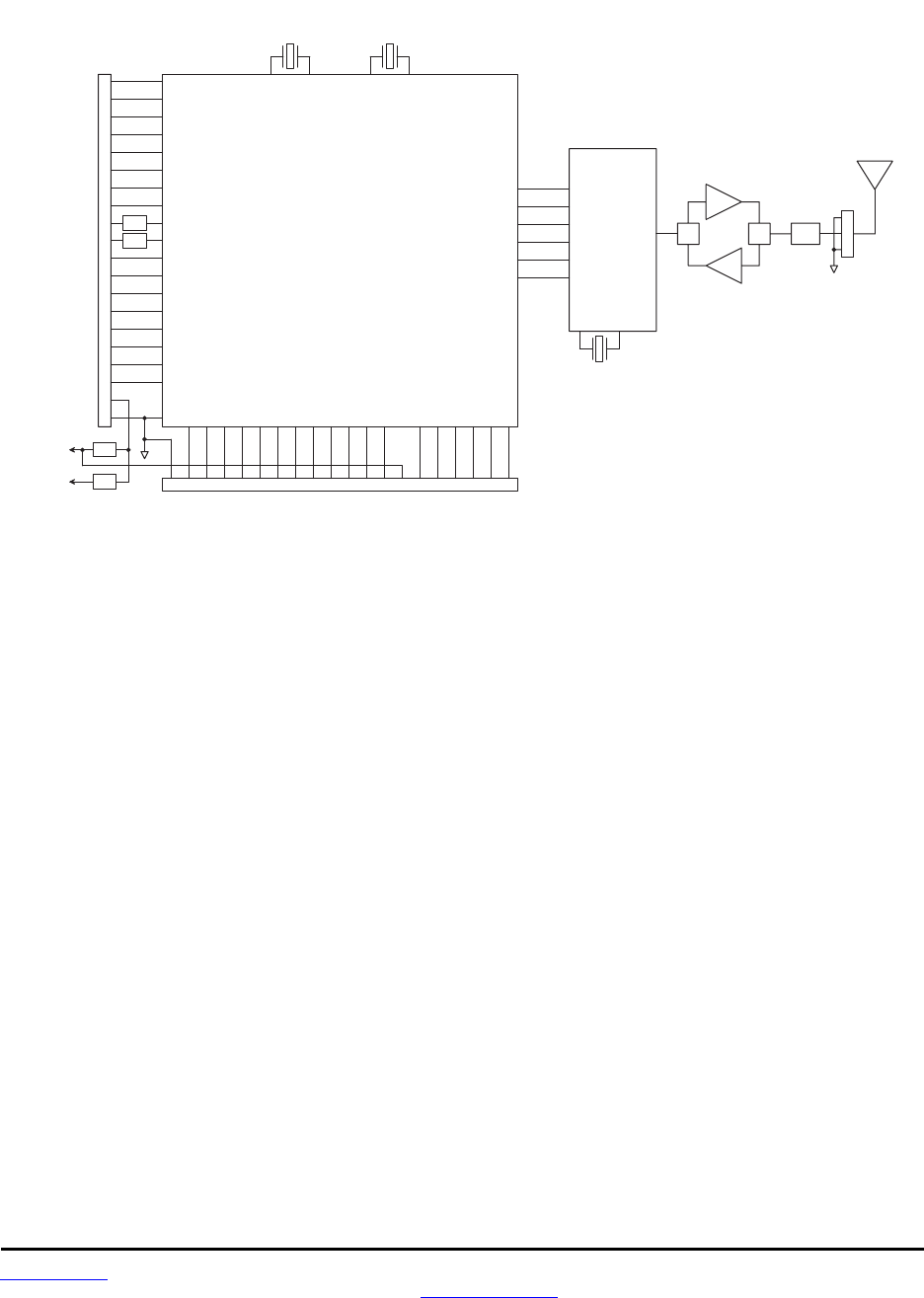
D N T 2 4 0 0 B l o c k D i a g r a m
3 2 3 3 3 4 3 6
M i c r o c o n t r o l l e r
4
3
2
1
R e g
F i l t e r
F i l t e r
V C C
P W M 0
P W M 1
G P I O 0
G P I O 1
G P I O 2
G P I O 3
G N D
4 2
R F
T r a n s c e i v e r
C L K
I N T
C S n R F I O
G N D
R A D I O _ T X D
R A D I O _ R X D
/ R E S E T
R S V D
R S V D
R S V D
T / R
T / R
P W R
P R E
F i l t e r
3 5
4 1
4 3
1 9
2 0
3 7 3 8 3 9 4 0
S I
S O
P K T D E T
R e g
3 . 3 V
3 . 6 V
P K T _ D E T
R S V D
A D C _ R E F
R S S I
S L E E P
A D C 2
A D C 1
A D C 0
E X _ S Y N C
D I A G _ T X
D I A G _ R X
/ C F G
/ H O S T _ R T S
/ H O S T _ C T S
G P I O 4
G P I O 5
G N D
A C T
/ D C D
R S V D
R S V D
R S V D
V M O D
R S V D
R S V D
Figure 3.0.1
The major components of the DNT2400 include a 2.4 GHz FHSS transceiver and a low current 32-bit
microcontroller. The DNT2400 operates in the 2.4 GHz ISM band. The module includes nine frequency
subbands and 37 total frequency channels to support the various 2.4 GHz frequency allocations used
throughout the world. The DNT2400 has three selectable RF output power levels: 1, 10, and 63 mW.
Also, there are four selectable RF transmission rates: 38.4, 115.2, 200 and 500 kb/s. The DNT2400
includes a low-noise receiver preamplifier and a high efficiency transmitter amplifier, providing excellent
range in outdoor applications.
The DNT2400 provides a variety of hardware interfaces. There are two UART serial ports, one for data
and a second for diagnostics. The data port supports standard baud rates from 1.2 to 460.8 kb/s, with the
diagnostic port fixed at 38.4 kb/s. The module also includes three 10-bit ADC inputs, two 8-bit PWM
outputs, and six general-purpose digital I/O ports. Four of the digital I/O ports support an optional inter-
rupt-from-sleep mode when configured as inputs. The radio is available in two mounting configurations.
The DNT2400C is designed for solder reflow mounting, and the DNT2400P is designed for plug-in con-
nector mounting.

www.RFM.com Technical support +1.678.684.2000 Page 25 of 81
©2009 by RF Monolithics, Inc. E-mail: tech_sup@rfm.com DNT2400 - 08/06/09
3.1 DNT2400 Specifications
Characteristic Sym Minimum Typical Maximum Units
Operating Frequency Range 2409.3 2467.1 MHz
Hop Dwell Time 5 200 ms
Number of Frequency Hopping Subbands 9
Number of RF Channels in a Subband 15 37
Modulation FSK/MSK
RF Data Transmission Rates 38.4, 115.2, 200 and 500 kb/s
Receiver Sensitivity:
10-5 BER @ 38.4 kb/s -104 dBm
10-5 BER @ 200 kb/s -96 dBm
10-5 BER @ 500 kb/s -90 dBm
Transmitter RF Output Power Levels 1, 10, 63 mW
Optimum Antenna Impedance 50 Ω
RF Connection DNT2400P - U.FL Connector
DNT2400C - U.FL Connector or PCB Pad
Network Topologies Point-to-Point, Point-to-Multipoint
Access Schemes TDMA and CSMA
Number of Network Nodes:
TDMA 16
CSMA unlimited
ADC Input Range 0 3.3 V
ADC Input Resolution 10 bits
Signal Source Impedance for ADC Reading 10 KΩ
PWM (DAC) Output Range 0 3.3 V
PWM (DAC) Output Resolution 8 bits
PWM Output Period 20 µs
Primary Serial Port Baud Rates 1.2, 2.4, 4.8, 9.6, 19.2, 28.8, 38.4, 57.6, 76.8,
115.2, 230.4, 460.8 kb/s
Diagnostic Serial Port Baud Rate 38.4 kb/s
Digital I/O:
Logic Low Input Level -0.5 0.8 V
Logic High Input Level 2 3.3 V
Logic Input Internal Pull-up Resistor 50 200 KΩ
Logic Input Internal Pull-down Resistor 50 180 KΩ
Power Supply Voltage Range VCC +3.3 +5.5 Vdc
Power Supply Voltage Ripple 10 mVP-P
Peak Transmit Mode Current, 63 mW Output 300 mA
Average Operating Receive Current:
Base 105 mA
Remote, No Data Transmission 35 mA
Remote, 9.6 kb/s Continuous Data Stream 40 mA
Remote, 115.2 kb/s Continuous Data Stream 53 mA
Sleep Current 50 2251 µA
Operating Temperature Range -40 85 oC
Operating Relative Humidity Range (non condensing) 10 90 %
1. Maximum sleep current occurs at +85 oC Table 3.1.1

www.RFM.com Technical support +1.678.684.2000 Page 26 of 81
©2009 by RF Monolithics, Inc. E-mail: tech_sup@rfm.com DNT2400 - 08/06/09
3.2 Module Interface
Electrical connections to the DNT2400C are made through the I/O pads and through the I/O pins on the
DNT2400P. The hardware I/O functions are detailed in the table below:
Pad Name I/O Description
1 PKT_DET O
Packet detect output. Signal switches logic high at the end of the start-of-packet symbol and
switches logic low at the end of the end-of-packet symbol on both received and transmitted packets.
PKT_DET provides a timing reference for use in network timing evaluations, etc.
2 RSVD - Reserved pad. Leave unconnected.
3 ADC_REF I ADC supply and external full scale reference voltage input. Voltage range is 2.4 to 3.3 Vdc. Connect
pad 34 to this input to reference the ADC full scale reading to the module’s 3.3 V regulated supply.
4 RSVD - Reserved pad. Leave unconnected.
5 GPIO0 I/O
Configurable digital I/O port 0. When configured as an input, an internal pull-up resistor can be
selected and interrupt from sleep can be invoked. When configured as an output, the power-on state
is also configurable.
6 GPIO1 I/O Configurable digital I/O port 1. Same configuration options as GPIO0.
7 GPIO2 I/O Configurable digital I/O port 2. Same configuration options as GPIO0.
8 GPIO3 I/O Configurable digital I/O port 3. Same configuration options as GPIO0.
9 PWM0 O 8-bit pulse-width modulated output 0 with internal low-pass filter. Filter is 1st order, 159 Hz 3 dB BW.
10 PWM1 O 8-bit pulse-width modulated output 1 with internal low-pass filter. Filter is 1st order, 159 Hz 3 dB BW.
11 SLEEP/DTR I Default functionality is active high module sleep input (active low DTR). When switched low after
sleep, the module executes a power-on reset. Usually connected to host DTR.
12 ADC2 I 10-bit ADC input 0. Full scale reading is referenced to the ADC_REF input.
13 ADC1 I 10-bit ADC input 1. Full scale reading is referenced to the ADC_REF input.
14 ADC0 I 10-bit ADC input 2. Full scale reading is referenced to the ADC_REF input.
15 EX_SYNC I
Rising-edge triggered input for synchronizing co-located bases. Synchronization pulse interval must
equal the hop dwell time ±10 µs. Pulse width must be in the range of 50 µs to 2 ms.
16 DIAG_TX O Diagnostic UART transmitter output.
17 DIAG_RX I Diagnostic UART receiver input.
18 /CFG I
Protocol selection input. Leave unconnected when using software commands to select transpar-
ent/protocol mode (default is transparent mode). Logic low selects protocol mode, logic high selects
transparent mode.
19 VCC I Power supply input, +3.3 to +5.5 Vdc.
20 GND - Power supply and signal ground. Connect to the host circuit board ground.
21 GND - Power supply and signal ground. Connect to the host circuit board ground.
22 GPIO4
I/O Configurable digital I/O port 4. When configured as an input, an internal pull-up resistor can be
selected. When configured as an output, the power-on state is configurable.
23 GPIO5 I/O Configurable digital I/O port 5. Same configuration options as GPIO4.
24 GND - Logic ground.
25 ACT O Data activity output, logic high when data is being transmitted or received.
26 /DCD O
Default functionality is data carrier detect output, which provides a logic low on a remote when the
module is locked to FHSS hopping pattern and logic low on a base when at least one remote is
connected to it.
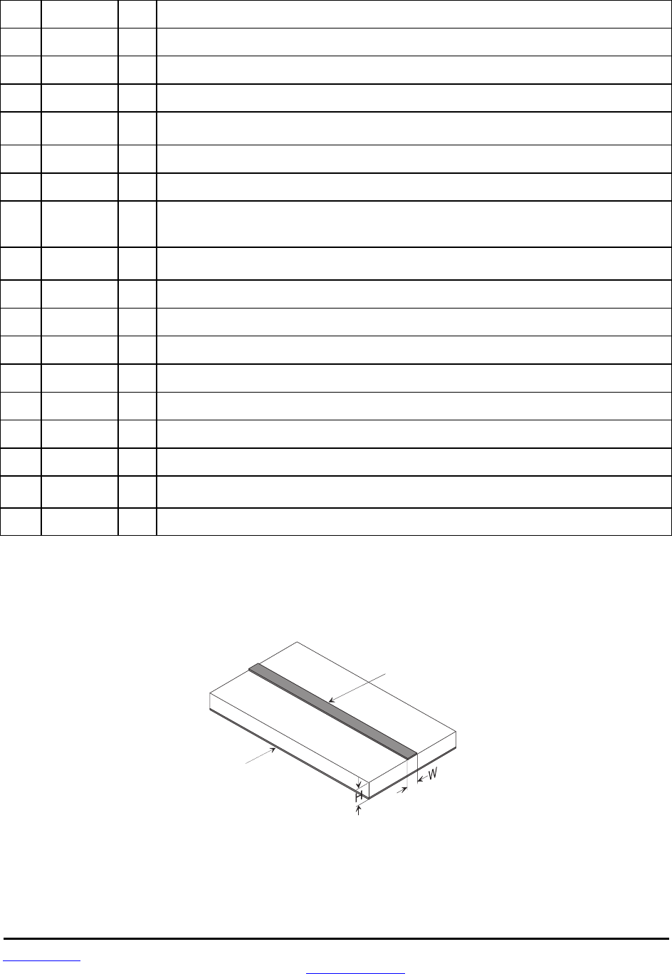
www.RFM.com Technical support +1.678.684.2000 Page 27 of 81
©2009 by RF Monolithics, Inc. E-mail: tech_sup@rfm.com DNT2400 - 08/06/09
Pad Name I/O Description
27 RSVD - Reserved pad. Leave unconnected.
28 RSVD - Reserved pad. Leave unconnected.
29 RSVD - Reserved pad. Leave unconnected.
30 /HOST_RTS I UART flow control input. The host sets this line low to allow data to flow from the DNT2400 on the
RADIO_TXD pin. When the host sets this line high, the DNT2400 will stop sending data.
31 RADIO_TXD O UART transmitter output. The DNT2400 sends serial data to the host on this pin.
32 RADIO_RXD I UART receiver input. The DNT2400 receives serial data from the host on this pin.
33 /HOST_CTS O
UART flow control output. The DNT2400 sets this line low to indicate it is ready to accept data from
the host on the RADIO_RXD input. When the DNT2400 sets this line high, the host must stop
sending data.
34 VMOD O Module’s +3.3 V regulated supply output. Connect to pad 3 to support 3.3 V full scale and/or
ratiometric ADC readings, etc. Current drain on this output should be no greater than 5 mA.
35 RSVD - Reserved pad. Leave unconnected.
36 RSVD - Reserved pad. Leave unconnected.
37 RSVD - Reserved pad. Leave unconnected.
38 RSVD - Reserved pad. Leave unconnected.
39 /RESET I Active low module hardware reset.
40 RSVD - Reserved pad. Leave unconnected.
41 GND - RF ground (DNT2400C only). Connect to the host circuit board ground plane.
42 RFIO
I/O Alternate RF port to the U.FL connector (DNT2400C only). The antenna can be connected to this port with
a 50 ohm stripline or coaxial cable. Leave unconnected when using the U.FL connector.
43 GND - RF ground (DNT2400C only). Connect to the host circuit board ground plane.
Table 3.2.1
3.3 DNT2400C RFIO Stripline
C o p p e r
G r o u n d
P l a n e
C o p p e r
S t r i p l i n e
T r a c e
F R - 4 P C B
M a t e r i a l
C i r c u i t B o a r d S t r i p l i n e T r a c e D e t a i l
F o r 5 0 o h m i m p e d a n c e W = 1 . 7 5 * H
Figure 3.3.1
The DNT2400C has a U.FL coaxial connector mounted near pad 42 for antenna connection (see Antenna
Connector discussion below). It is also possible to connect an antenna using a stripline from pad 42. It is

www.RFM.com Technical support +1.678.684.2000 Page 28 of 81
©2009 by RF Monolithics, Inc. E-mail: tech_sup@rfm.com DNT2400 - 08/06/09
important that this connection be implemented as a 50 ohm stripline. Referring to Figure 3.3.1, the width
of this stripline depends on the thickness of the circuit board between the stripline and the groundplane.
For FR-4 type circuit board materials (dielectric constant of 4.7), the width of the stripline is equal to 1.75
times the thickness of the circuit board. Note that other circuit board traces should be spaced away from
the stripline to prevent signal coupling, as shown in Table 3.3.1. The stripline trace should be kept short to
minimize its insertion loss.
Trace Separation from
50 ohm Microstrip
Length of Trace Run
Parallel to Microstrip
100 mil 125 mill
150 mil 200 mil
200 mil 290 mil
250 mil 450 mil
300 mil 650 mil
Table 3.3.1
3.4 DNT2400 Antenna Connector
A U.FL miniature coaxial connector is provided on both DNT2400 configurations for connection to the
RFIO port. A short U.FL coaxial cable can be used to connect the RFIO port directly to an antenna. In this
case the antenna should be mounted firmly to avoid stressing the U.FL coaxial cable due to antenna
mounting flexure. Alternately, a U.FL coaxial jumper cable can be used to connect the DNT2400 module
to a U.FL connector on the host circuit board. The connection between the host circuit board U.FL con-
nector and the antenna or antenna connector on the host circuit board should be implemented as a 50
ohm stripline. Referring to Figure 3.3.1, the width of this stripline depends on the thickness of the circuit
board between the stripline and the groundplane. For FR-4 type circuit board materials (dielectric con-
stant of 4.7), the width of the stripline is equal to 1.75 times the thickness of the circuit board. Note that
other circuit board traces should be spaced away from the stripline to prevent signal coupling, as shown
in Table 3.3.1. The stripline trace should be kept short to minimize its insertion loss.
3.5 Input Voltages
DNT2400 radio modules can operated from an unregulated DC input (Pad 19) in the range of 3.3 (trough)
to 5.5 V (peak) with a maximum ripple of 5% over the temperature range of -40 to 85 oC. Applying AC,
reverse DC, or a DC voltage outside the range given above can cause damage and/or create a fire and
safety hazard. Further, care must be taken so logic inputs applied to the radio stay within the voltage
range of 0 to 3.3 V. Signals applied to the analog inputs must be in the range of 0 to ADC_REF (Pad/Pin
3). Applying a voltage to a logic or analog input outside of its operating range can damage the DNT2400
module.
3.6 ESD and Transient Protection
The DNT2400C and DNT2400P circuit boards are electrostatic discharge (ESD) sensitive. ESD precau-
tions must be observed when handling and installing these components. Installations must be protected
from electrical transients on the power supply and I/O lines. This is especially important in outdoor instal-
lations, and/or where connections are made to sensors with long leads. Inadequate transient protection
can result in damage and/or create a fire and safety hazard.

www.RFM.com Technical support +1.678.684.2000 Page 29 of 81
©2009 by RF Monolithics, Inc. E-mail: tech_sup@rfm.com DNT2400 - 08/06/09
3.7 Interfacing to 5 V Logic Systems
All logic signals including the serial ports on the DNT2400 are 3.3 V signals. To interface to 5 V signals,
the resistor divider network shown in Figure 3.5.1 below must be placed between the 5 V signal outputs
and the DNT2400 signal inputs. The output voltage swing of the DNT2400 3.3 V signals is sufficient to
drive 5 V logic inputs.
5 V
L o g i c D N T 5 0 0
2 . 2 K
4 . 3 K
Figure 3.7.1
3.8 Power-On Reset Requirements
When applying power to the DNT2400, the /RESET pin should be held low until the power supply voltage
reaches 3.3 volts for 100 milliseconds.
3.9 Mounting and Enclosures
DNT2400C radio modules are mounted by reflow soldering them to a host circuit board. DNT2400P
modules are mounted by plugging their pins into a set of mating connectors on the host circuit board.
Refer to Section 8.3 and/or the DNT2400 Data Sheet for DNT2400P connector details.
DNT2400 enclosures must be made of plastics or other materials with low RF attenuation to avoid com-
promising antenna performance where antennas are internal to the enclosure. Metal enclosures are not
suitable for use with internal antennas as they will block antenna radiation and reception. Outdoor enclo-
sures must be water tight, such as a NEMA 4X enclosure.
3.10 Labeling and Notices
DNT2400 FCC Certification - The DNT2400 hardware has been certified for operation under FCC Part 15
Rules, Section 15.247.
DNT2400 FCC Notice - This device complies with Part 15 of the FCC rules. Operation is subject to the
following two conditions: (1) this device may not cause harmful interference, and (2) this device must
accept any interference received, including interference that may cause undesired operation.
DNT2400 FCC Label - A clearly visible label is required on the outside of the user’s (OEM) enclosure
stating ”Contains FCC ID: HSW-DNT2400.”
WARNING: This device operates under Part 15 of the FCC rules. Any modification to this device, not
expressly authorized by RFM, Inc., may void the user’s authority to operate this device.
DNT2400

www.RFM.com Technical support +1.678.684.2000 Page 30 of 81
©2009 by RF Monolithics, Inc. E-mail: tech_sup@rfm.com DNT2400 - 08/06/09
Canadian Department of Communications Industry Notice - IC: 4492A-DNT2400
This apparatus complies with Health Canada’s Safety Code 6 / IC RSS-210.
IC RSS-210 Notice - Operation is subject to the following two conditions: (1) this device may not cause
interference, and (2) this device must accept any interference, including interference that may cause
undesired operation of the device.
Canadian ICES-003 - This digital apparatus does not exceed the Class B limits for radio noise emissions
from digital apparatus as set out in the radio interference regulations of Industry Canada.
Le present appareil numerique n’emet pas de bruits radioelectriques depassant les limites applicables
aux appareils numeriques de Classe B prescrites dans le reglement sur le brouillage radioelectrique
edicte par Industrie Canada.

www.RFM.com Technical support +1.678.684.2000 Page 31 of 81
©2009 by RF Monolithics, Inc. E-mail: tech_sup@rfm.com DNT2400 - 08/06/09
4.0 Protocol Messages
4.1 Protocol Message Formats
The DNT2400 is configured and controlled through a series of protocol mode messages. All protocol
mode messages have a common header format:
0 1 2 3 …
SOP
Length PktType variable number of arguments …
Figure 4.1.1
The scale above is in bytes.
The Start-of-Packet (SOP) character, 0xFB, is used to distinguish the beginning of a message and to
assure synchronization in the event of a glitch on the serial port at startup.
The Length byte is defined as the length of the remainder of the message following the length byte itself
(or the length of the entire message - 2).
The Packet Type (PktType) byte specifies the type of message. It is a bitfield-oriented specifier, decoded
as follows:
Bits 7-6 Reserved for future use
Bit 5 Event - set to indicate this message is an event
Bit 4 Reply - set to indicates this message is a reply
Bits 3-0 Type - indicates the message type/command
As indicated, the lower 4 bits (3-0) specify a message type. Bit 4 is a modifier indicating that the message
is a command or a reply. A reply message has the original command type in bits 3:0, with bit 4 set to one.
Arguments vary in size and number depending on the type of message and whether it is a message sent
from the host or is a reply from the radio; see Table 4.1.2.1 below. Messages that are generated on the
serial interface by the user are referred to as host messages. Messages that are generated by the radio
are referred to as reply messages. For many message types, there is a reply message that corresponds
to a host message. For example, when the host sends a TxData message, the radio will reply to indicate
the status of the transmission, whether it succeeded or failed. Some message types are host-only or
reply-only; refer to Table 4.1.2.1 for specifics.
4.1.1 Message Types
Each message generally has two forms, a command from the host and a reply from the radio. Depending
on the direction, they have different arguments as shown in Table 4.1.2.1. Event messages from the radio
such as received data packets or status announcements make up a third category of messages. To assist
in interpreting the command-reply data flow, the direction is indicated by the high nibble in the message
type. For example, an EnterProtocolMode command from the host is a message type 0x00, and the
EnterProtocolModeReply from the radio is a message type 0x10. Event messages, including RxData,
RxEvent and Announce packets are indicated by 0x20 in the high nibble of the type byte. If multiple
arguments are to be provided, they are to be concatenated in the order shown. Little-Endian byte format

www.RFM.com Technical support +1.678.684.2000 Page 32 of 81
©2009 by RF Monolithics, Inc. E-mail: tech_sup@rfm.com DNT2400 - 08/06/09
is used for all multi-byte arguments, where the lowest order byte is the left-most byte of the argument and
the highest order byte in the right-most byte of the argument.
4.1.2 Message Format Details
Com-
mand Reply Event Description Direction Arguments
0x00 - - EnterProtocolMode from Host DNT2400 (ASCII characters)
- 0x10 - EnterProtocolModeReply from Radio none
0x01 - - ExitProtocolMode from Host none
- 0x11 - ExitProtocolModeReply from Radio none
0x02 - - SoftwareReset from Host BootSelect
- 0x12 - SoftwareResetReply from Radio none
0x03 - - GetRegister from Host Reg, Bank, Span
- 0x13 - GetRegisterReply from Radio Reg, Bank, Span,Val
0x04 - - SetRegister from Host Reg, Bank, Span, Val
- 0x14 - SetRegisterReply from Radio none
0x05 - - TxData from Host Addr, Data
- 0x15 - TxDataReply from Radio TxStatus, Addr, RSSI
- - 0x26 RxData from Radio Addr, RSSI, Data
- - 0x27 Announce from Radio AnnStatus, additional fields
- - 0x28 RxEvent from Radio Addr, RSSI, Reg, Bank, Span,Val
0x0A - - GetRemoteRegister from Host Addr, Reg, Bank, Span
- 0x1A - GetRemoteRegisterReply from Radio
If command successful:
TxStatus, Addr, RSSI,
Reg, Bank, Span, Val
If command failed:
TxStatus, Addr
0x0B - - SetRemoteRegister from Host Addr, Reg, Bank, Span, Val
- 0x1B - SetRemoteRegisterReply from Radio TxStatus, Addr, RSSI
- - 0x2C JoinRequest from Radio Addr,3 Reserved Bytes ,
0x0C - - JoinReply from Host Addr, PermitStatus
0x0D - - RemoteLeave from Host Addr, BackOffTime
Table 4.1.2.1
Arguments:
Reg = Register location (1 byte)
Bank = Register bank, which provides logical isolation from other data regions (1 byte)
Span = Number of bytes of register data to get or set; must align to a parameter boundary (1 byte)
Val = Value to read/write to/from a register (see table 4.1.2.1 for size and acceptable range).
Data = User data (must fit within the slot size allocation)
Addr = the MAC address of the destination node in a command, the MAC address of a node sending a
reply or event message, or the MAC address of the originating node in an RxData message (3 bytes)
TxStatus = Result of last TxData operation (1 byte)
0 = Acknowledgement received
1 = No acknowledgement received
2 = Not linked (remote)
3 = No ACK due to recipient holding for flow control

www.RFM.com Technical support +1.678.684.2000 Page 33 of 81
©2009 by RF Monolithics, Inc. E-mail: tech_sup@rfm.com DNT2400 - 08/06/09
RSSI = 2’s complement value in dBm, with a range of -128 (0x80) to +125 (0x7D) dBm (1 byte);
large positive RSSI values will not occur under ordinary circumstances. RSSI values 126 (0x7E)
and 127 (0x7F) have special meaning:
0x7F = No RSSI measured because no ACK was received
0x7E = reserved for future use
NwkID = Network identifier of network joined (1 byte).
BaseMacAddr = MAC address of base that the remote joined (3 bytes).
AnnStatus = Status announcement (1 byte). Additional fields are also reported
depending on the status code:
Status code Additional fields
A0 = Radio has completed startup initialization none
A2 = Base: a remote has joined the network Addr, reserved, Range
A3 = Remote: joined a network, ready for data NwkID, BaseMacAddr, Range
A4 = Remote: exited network (base is out of range) NwkID
A7 = Base: remote has left the network. Addr
Status codes for error conditions Additional fields
E0 = Protocol error - invalid message type none
E1 = Protocol error - invalid argument none
E2 = Protocol error - general error none
E3 = Protocol error - parser timeout none
E4 = Protocol error - register is read-only none
E8 = UART receive buffer overflow none
E9 = UART receive overrun none
EA = UART framing error none
Range = Range measurement of joining radio (1 byte). Each count equals 0.29 miles.
BootSelect = Code indicating whether to do a normal reset or a reset to the bootloader (1 byte)
(0 = normal reset, 1 = reset to bootloader)
PermitStatus = Permission for new node to join, 0x00 = denied, 0x01 = permitted (1 byte)
BackoffTime = Time that a node will avoid trying to join a network, in seconds (2 bytes)
(0xFFFF = back off until reset or power cycled)
4.1.3 /CFG Select Pin
A falling edge on the /CFG pin is the equivalent of the EnterProtocolMode command. A rising edge on the
/CFG pin is the equivalent to sending the ExitProtocolMode command. The input to the /CFG pin is de-
bounced to make it compatible with a mechanical switch or jumper.
4.1.4 Flow Control
There are two flow control signals between the radio and the host, /HOST_RTS and /HOST_CTS. See
Section 2.11 for flow control details.

www.RFM.com Technical support +1.678.684.2000 Page 34 of 81
©2009 by RF Monolithics, Inc. E-mail: tech_sup@rfm.com DNT2400 - 08/06/09
4.1.5 Protocol Mode Data Message Example
In this example, ASCII text Hello World is sent from the base to a remote using a TxData command. The
MAC address of the remote is 0x000102. The protocol formatting for the host message is:
0xFB 0x0F 0x05 0x02 0x01 0x00 0x48 0x65 0x6C 0x6C 0x6F 0x20 0x57 0x6F 0x72 0x6C 0x64
There are 15 bytes following the length byte, so the length byte is set to 0x0F. Note that the 0x000102
MAC address is entered in Little-Endian byte order 0x02 0x01 0x00.
When an ACK to this message is received from the remote, the base outputs a TxDataReply message to
its host:
0xFB 0x06 0x15 0x00 0x02 0x01 0x00 0xC4
The 0x00 TxStatus byte value indicates the ACK reception from the remote. The RSSI value of the re-
ceived ACK is 0xC4 (-60 dBm).
If the remote is in protocol mode, the message is output in the following format:
0xFB 0x10 0x26 0x00 0x00 0x00 0xC4 0x48 0x65 0x6C 0x6C 0x6F 0x20 0x57 0x6F 0x72 0x6C 0x64
The message is output as an 0x26 event. The address field contains the base (originator) address. Note
that the RSSI value 0xC4 is inserted between the base MAC address and the Hello World user data.
4.2 Configuration Registers
The configuration registers supported by the DNT2400 are described below. Registers are sorted into
banks according to similar functions. Default register values are in bold. All changes to parameters are
temporary and will not persist through power cycling until 0x01 has been written to the MermorySave
parameter in Bank FF. Writing 0x00 to the MemorySave parameter will reload the factory default values
which also require writing 0x01 to the MemorySave location. Also note that some parameter changes do
not take effect until they are saved and the module is reset or power cycled. Modules can be reset by
writing 0x00 to the UcReset parameter in Bank FF.
4.2.1 Bank 0 - Transceiver Setup
Size in
Bank Loc'n Name R/W bytes Range Default, Options
00 00 DeviceMode R/W 1 0..2 0 = Remote, 1= Base, 2 = PTT Remote
00 01 RF_DataRate R/W 1 0..4 0 = 500, 1 = 200, 2 = 115.2, 3 = 38.4 kb/s,
0XFF = auto
00 02 HopDuration R/W 2 4..4000 10 ms (0x00C8)
00 04 InitialNwkID R/W 1 0..255 0xFF = join any network
00 05 SecurityKey R/W 16 0..2128 all null bytes (0x00) = security disabled
00 15 SleepMode R/W 1 0..1 0 = off, 1 = timer, 2 = interrupt
00 16 WakeResponseTime R/W 1 0..255 1 = 50 ms, 0 to disable
00 17 WakeLinkTimeout R/W 1 0..255 5 s
00 18 TxPower R/W 1 0..2 0 = 1 mW; 1 = 10 mW, 2 = 63 mW
00 19 ExtSyncEnable R/W 1 0..1 0 = off; 1 = enable
00 1A DiversityMode R/W 1 0..2 0 = 0 V, 1 = 3.3 V, 2 = toggle
00 1B Reserved 1
00 1C UserTag R/W 16 "DNT2400"
00 2C RegDenialDelay R/W 2 10 s
00 2E RmtTransDestAddr R/W 3 0x000000 (Base)
Note: These settings are individual to each module.

www.RFM.com Technical support +1.678.684.2000 Page 35 of 81
©2009 by RF Monolithics, Inc. E-mail: tech_sup@rfm.com DNT2400 - 08/06/09
DeviceMode - selects the operating mode for the radio: remote, base, or PTT remote (listen mostly
remote). Note that changing this setting does not take effect immediately. It must be followed by a Mem-
orySave command (See Section 4.2.9) and then a hardware reset.
RF_DataRate - this sets the over-the-air data rate. DNT2400’s with different RF data rates cannot inter-
communicate. The following codes are defined:
0x00 = 500 kb/s (default)
0x01 = 200 kb/s
0x02 = 115.2 kb/s
0x03 = 38.4 kb/s
0xff = auto
The auto setting will cause a remote to try all four over-the-air rates when scanning for a network to join.
Setting the RF_DataRate to a fixed value on the remotes will allow a network to link much faster than
using the auto setting. However, if the base RF_DataRate is changed when the remotes are set to a fixed
rate, the network will not link. Note that changing this setting does not take effect immediately. It must be
followed by a MemorySave command (See Section 4.2.9) and then a hardware reset.
HopDuration - this sets the duration of the hop frame. The duration is set as a 12-bit value,
0.05 ms/count. Changing the hop duration must be followed by a MemorySave command to allow the
change to persist through a reset or power cycle. A HopDuration change takes effect immediately. Re-
motes will re-link following a HopDuration parameter change.
InitialNwkID - selects the initial network ID that the radio will start (if a base) or join (if a remote). A value
of 0xFF instructs a remote to operate in 'promiscuous mode' and join any network it finds (if set for a
base, this will select the default network ID of 0x00.) The network ID also sets the base frequency at
which the hopping pattern starts, as illustrated by the following equation:
FrequencyIndex[n] = HoppingPattern[n + NetworkID mod 32]
This allows the user to coordinate frequency spacing of co-located networks to maintain a constant sepa-
ration as they hop. The InitialNwkID values of co-located networks should be two apart (0, 2, 4 … or 1, 3,
5 …) for best results.
SecurityKey - this sets the 128-bit AES encryption key to be used. To protect the key, this is a write-only
parameter for the user (always reads back as 0x2A). Refer to the Section 2.13 for further information.
SleepMode - this parameter enables sleep mode, which may be used in conjunction with the automatic
I/O reporting feature to wake up on specified triggers. Sleep mode is only available for remotes, and the
channel access mode for the network must be one of the CSMA modes.
WakeResponseTime - this parameter sets the length of time that a remote in sleep mode will wait for a
response after sending an I/O report before going back to sleep, from a minimum of 10 ms to a maximum
of 2.5 seconds in 10 ms units. This time interval is set to allow the base host application to respond to a
remote with a packet before the remote returns to sleep. If this parameter is set to 0, the remote will stay
awake indefinitely after sending an I/O report. This allows the application as much time as needs for any
initial configuration after which it can cause the remote to re-enter sleep by setting this to the operating
value.

www.RFM.com Technical support +1.678.684.2000 Page 36 of 81
©2009 by RF Monolithics, Inc. E-mail: tech_sup@rfm.com DNT2400 - 08/06/09
WakeLinkTimeout - this parameter sets the maximum length of time that a remote in sleep mode will
spend trying to acquire a link to its base before going back to sleep, from a minimum of 100 ms to 25.5 s
in 100 ms units. If this value is set to 0, the remote will stay awake and continue trying to link to its base
indefinitely.
TxPower - this parameter sets the transmit power level used by the base (fixed), and the maximum trans-
mit power level used by a remote. A remote may automatically adjust its power below the TxPower set-
tings based on the signal strength it receives from the base plus the TxPower setting being used by the
base. The default 1 mW TxPower setting is useful for desktop testing. TxPower is usually set to a higher
level to increase operating range in actual applications. Setting bit 4 (0001xxxx) disables the remote
automatic transmit power function.
0x00 = 0 dBm or 1 mW (default)
0x01 = 10 dBm or 10 mW
0x02 = 18 dBm or 63 mW
ExtSyncEnable - this parameter enables or disables the hardware EX_SYNC function on Pin 15. When
enabled, a pulse train can be input on Pin 15 to synchronize the transmission of co-located bases. Dis-
abled by default.
DiversityMode - the following diversity antenna switching options are supported as an output on GPIO5:
0 = 0 V output (default)
1 = 3.3 V output
2 = hop-by-hop toggle between 0 and 3.3 V
UserTag - this is a user definable field intended for use as a location description or other identifying tag
such as a “friendly name”.
RegDenialDelay - when a remote has been removed from a network through a RemoteLeave, the Reg-
DenialDelay parameter sets the length of time the remote will wait before considering that network a
candidate for joining again. Units are in seconds; the default is 10 s.
RmtTransDestAddr - this parameter sets the destination address that a remote will send packets to when
configured to use transparent mode. The default destination is the base (0x000000). If this field is set to
another remote's MAC address or to the broadcast address, a peer-to-peer packet will be sent. Note that
peer-to-peer packets have higher latency than direct packets between base and remote. This setting has
no effect on the base.
4.2.2 Bank 1 - System Settings
Size in
Bank Loc'n Name R/W bytes Range Default; Options
01 00 FrequencyBand R/W 1 0..FF 0x00 to 0x08 = general purpose,
0x04,
0x05 & 0x07 = France, 0xFF = auto
01 01 AccessMode R/W 1 0..4 2 = TDMA Dynamic Slots
01 02 BaseSlotSize R/W 1 6..233 50 bytes
01 03 LeasePeriod R/W 1 0..250 5 s (0 to disable)
01 04 ARQ_Mode R/W 1 0..3 1 = redundant broadcast to ARQ_AttemptLimit,
ARQAttemptLimit pass to remotes enabled
01 05 ARQ_AttemptLimit R/W 1 0..63 8 attempts
01 06 MaxSlots R/W 1 0..15 16 slots
01 07 CSMA_Predelaty R/W 1 0..255 0x03
01 08 CSMA_Backoff R/W 1 0..255 0x0A
01 09 MaxPropDelay R/W 1 0..255 0x45 (20 mi, 32.18 km)
01 0A LinkDropThreshold R/W 1 0..255 0x0C

www.RFM.com Technical support +1.678.684.2000 Page 37 of 81
©2009 by RF Monolithics, Inc. E-mail: tech_sup@rfm.com DNT2400 - 08/06/09
01 0B CSMA_RemtSlotSize R/W 1 1..255 50
01 0C CSMA_BusyThreshold R/W 1 1..255 20
01 0D RangingInterval R/W 1 0..255 0 = disable
01 0E AuthMode R/W 1 0..3 0 = authentication disabled
01 0F PeerReplyTimeout R/W 1 8 hops
Bank 1 holds configuration parameters to be input to the base only. The base passes these parameters to
the remotes as needed. The exception is the ARQ_AttemptLimit parameter. If ARQ_Mode bit 1 is set to 1
at the base, the ARQ_AttemptLimit parameter can be set in the remotes and used.
FrequencyBand - this parameter selects the frequency hopping subband. Nine subbands are available,
as shown below. Note that operation in France is limited to subbands 0x04, 0x05 and 0x07.
Subband Channels Frequency Range(s) Notes
0x00 37 2409.3-2467.1 MHz General purpose 37 channel subband
0x01 17 2441.1-2467.1 MHz 17 channel subband, avoids 802.11b/g channels 1-4
0x02 17 2409.3-2416.6 MHz, 2451.2-2467.1 MHz 17 channel subband, avoids 802.11b/g channels 5-6
0x03 17 2409.3-2426.7 MHz, 2461.3-2467.1 MHz 17 channel subband, avoids 802.11b/g channels 7-8
0x04 17 2409.3-2435.3 MHz 17 channel subband, avoids 802.11b/g channels 9-10,
also for use in France
0x05 21 2409.3-2441.1 MHz 21 channel subband, avoids 802.11b/g channels
11-13, also for use in France
0x06 21 2428.1-2461.3 MHz 21 channel subband, avoids 802.11 b/g channel 1
0x07 15 2409.3-2432.4 MHz 15 channel subband, avoids 802.11b/g channels
8-13, also for use in France
0x08 15 2433.9-2455.6 MHz 15 channel subband, avoids 802.11b/g channels
1-2 and 13
0xFF 15 to 37 Auto Autoscan for remote to match base
AccessMode - this sets the channel access mode that remotes will use to communicate with the base:
Access Mode Description Max # of Remotes Remote Slot Size
0 Polling unlimited manual
1 CSMA unlimited manual
2 (default) TDMA dynamic slots up to 16 automatic
3 TDMA fixed slots up to 16 automatic
4 TDMA with PTT up to 16 automatic
BaseSlotSize - This parameter set the maximum number of user data bytes that the base can send on a
single hop. This value must be set by the user for all access modes. The default value is 50 bytes.
LeasePeriod - this sets the duration in seconds for leases that remotes receive from the base. If a period
of zero is specified, then lease functions are disabled. The minimum valid lease period is two seconds.
Remotes will attempt to renew their leases at an interval equal to half the lease period. For example, if the
lease period is set to four seconds, remotes will renew their leases every two seconds.
ARQ_Mode - this sets the ARQ mode for delivery of application messages. In ARQ mode, an ACK is
expected from the receiving radio for each message addressed and sent to it. If no ACK is received, up to
ARQ_AttemptLimit, attempts to send the data will be made, after which the message is discarded. In
redundant broadcast mode, each broadcast message is sent exactly ARQ_AttemptLimit times. No ACKS
are sent or expected. The following bit options control this function:
bits 7..2 Not used
bit 1 If set to 0, the base can pass a new ARQ_AttemptLimit to the remotes
If set to 1, the remotes use their own ARQ_AttemptLimit in Bank 1
bit 0 If set to 1, ARQ mode is enabled for Protocol mode; the base will send broadcast packets ARQ_AttemptLimit
times instead of once. If set to 0, broadcast packets are sent once

www.RFM.com Technical support +1.678.684.2000 Page 38 of 81
©2009 by RF Monolithics, Inc. E-mail: tech_sup@rfm.com DNT2400 - 08/06/09
ARQ_AttemptLimit - this sets the maximum number of attempts that will be made to send a data packet
on the RF link. Setting this parameter to the maximum value of 63 is a flag value indicating that there
should be no limit to the number of attempts to send each packet (infinite number of attempts). This mode
is intended for point-to-point networks in serial data cable replacement applications where absolutely no
packets can be lost. Note - if this mode is used in a multipoint network, one remote that has lost link will
shut down the entire network if the base is trying to send it data.
MaxNumSlots - in TDMA access modes, this sets the number of slots that are allowed. In fixed slot mode,
this allocates the number of slots directly. In dynamic slot mode, this sets the maximum number of slots
that may be generated regardless of the number of remotes that attempt to link with the base. Any re-
motes requesting registration after this limit is reached will be denied registration by the base.
CSMA_Predelay - in CSMA mode 1, this parameter sets the maximum delay between when the base
transmission has finished and when a remote checks for a clear channel. Refer to Section 2.9.2 for more
information.
CSMA_Backoff - in a CSMA mode 1, this sets the length of time that a remote will back off after it detects
a busy channel. Refer to Section 2.9.2 for more information.
MaxPropDelay - this is the maximum propagation delay that the base and the remotes will use in their slot
timing calculations, in units of 3.1 µs. This is used to increase the amount of time dedicated to the regis-
tration slot. Increasing this value will subtract slightly from the overall slot time available to remotes for
sending data. Note that the free-space round trip propagation delay for one mile is 10.72 µs. Each incre-
ment of MaxPropDelay thus corresponds to a maximum radius from the remote to the base of 0.29 mi
(0.46 km). The default setting provides enough time to handle remotes up to 20 miles away. It is recom-
mended to use the default setting unless a path greater than 20 miles is planned at start up. Once linked
to the base, remotes will periodically update their timing based on ranging information from the base,
except in Polling Mode. The frequency with which this value is updated is set by the RangingInterval
parameter discussed below. The current range information is available in the CurrPropDelay parameter.
LinkDropThreshold - this is the number of consecutive beacons missed by a remote that causes the
remote to restart a link acquisition search. Please contact RFM technical support before making changes
to the parameter.
CSMA_RemtSlotSize - this sets the maximum size for a remote data transmission in polling or CSMA
channel access modes. Setting this parameter to a large value allows a remote to send more data in a
single hop, but can result in fewer remotes having time to send on a given hop. The default is 50 bytes.
CSMA_BusyThreshold - this sets the RSSI energy detection threshold that remotes use to determine
whether the channel is occupied. The factory default should be sufficient for most applications and it is
recommended that this value not be changed.
RangingInterval - this sets the period at which remotes will reassess their range to the base. Polling
(mode 0) disables the ranging interval mechanism, so remotes receive ranging information only once
each time they join a network. The RangingInterval timer does not advance while a remote is sleeping.
AuthMode - this parameter is valid on the base only. It controls how remotes are permitted to join the
network. Permitted values are:

www.RFM.com Technical support +1.678.684.2000 Page 39 of 81
©2009 by RF Monolithics, Inc. E-mail: tech_sup@rfm.com DNT2400 - 08/06/09
0 = Any remote may join
1 = Authentication by base radio permission table
2 = Authentication by request to host application
3 = Lock authentication to permit only currently registered remotes
PeerReplyTimeout - This sets the reply timeout for peer-to-peer packets sent from one remote to another.
Because each leg of the journey from one remote to another and back may take multiple transmit at-
tempts, the length of time to confirm receipt and issue a TxDataReply is subject to more variation than a
normal transmission between base and remote. The PeerReplyTimeout parameter specifies the maxi-
mum number of hops that a remote will wait for a reply from its recipient. If a reply returns sooner than the
timeout, the remote will send a TxDataReply indicating success to its host as soon as it is received and
cancel the timeout. If a reply does not come back before the timeout expires, the remote will send a
TxDataReply to its host indicating failure. If a reply should come back after the timeout expires the remote
will ignore it, as a TxDataReply has already been sent. Units are in hops; the default is 8 hops.
4.2.3 Bank 2 - Status Registers
Size in
Bank Loc'n Name R/W bytes Range Default
02 00 MacAddress R 3 0..0x0ffffff fixed value
02 03 Reserved R 1 0..255 reserved
02 04 CurrNwkID R 1 0..255 as set
02 05 CurrRF_DataRate R 1 0..4 as set
02 06 CurrFreqBand R 1 0..1 as set
02 07 LinkStatus R 1 0..1 current status
02 08 RemoteSlotSize R 1 0..243 as set
02 09 TDMA_NumSlots R 1 0..16 as set
02 0A Reserved R 1 0..255 reserved
02 0B TDMA_CurrSlot R 1 0..16 current slot
02 0C HardwareVersion R 1 0..255 0x00 = DNT2400 rev A
02 0D FirmwareVersion R 1 0..255 current firmware load
02 0E FirmwareBuildNum R 2 0..216 current firmware load
02 10 Reserved R 1 0..255 reserved
02 11 SuperframeCount R 1 0..255 current value
02 12 RSSI_Idle R 1 0..255 as set
02 13 RSSI_Last R 1 0..255 as set
02 14 CurrTxPower R 1 0..255 as set
02 15 CurrAttemptLimit R 1 0..255 as set
02 16 CurrRangeDelay R 1 0..255 as set
02 17 FirmwareBuildDate R 8 ASCII as set
02 1F FirmwareBuildTime R 8 ASCII as set
02 27 ModelNumber R 1 0..255 0x02
MacAddress - returns the radio's unique 24-bit MAC address.
CurrNwkID - This returns the network ID of the network that the radio is currently assigned to or con-
nected to. A value of 0xFF means the radio is scanning for a network but has not yet joined one.
CurrRF_DataRate - this returns the RF data rate of the network that the radio is currently assigned to or
connected to. A value of 0xFF means the radio is scanning for a network but has not yet joined one.
CurrFreqBand - this returns the frequency band of the network that the radio is currently assigned to or
connected to. A value of 0xFF means the radio is scanning for a network but has not yet joined one.

www.RFM.com Technical support +1.678.684.2000 Page 40 of 81
©2009 by RF Monolithics, Inc. E-mail: tech_sup@rfm.com DNT2400 - 08/06/09
LinkStatus - this returns the radio's current connection status to the network. The following codes are
defined:
LinkStatus Remote Status Base Status
0 initializing initializing
1 unlinked, scanning for a network not used
2 linked, acquiring network parameters not used
3 linked, registering with the base not used
4 linked and registered ready for data transfer
RemoteSlotSize - returns the current remote slot size, defined as the maximum number of bytes a remote
can send on a single hop. When using protocol mode, the entire packet, including overhead bytes must
be less than or equal to this value or the packet will be discarded. In the three TDMA modes the remote
slot size is automatically computed, and this value is read-only. In polling and CSMA modes, the remote
slot size must be set by the user. The parameter to set this is CSMA_RemtSlotSize in Bank 1.
TDMA_NumSlots - in TDMA access modes, this returns the number of slots currently allocated.
TDMA_CurrSlot - returns the current TDMA slot number assigned to the remote in modes where the slot
position is automatically computed. In modes where this number is not applicable, it is read as 0xFF.
HardwareVersion - returns an identifier indicating the type of radio. A value of 0x41 is defined for the
DNT2400 Rev A hardware.
FirmwareVersion - returns the firmware version of the radio in 2-digit BCD format.
FirmwareBuildNum - returns the firmware build number, in binary format.
SuperframeCount - returns the current superframe count. The count increments every 64 hops.
RSSI_Idle - returns the last measurement of RSSI made during a time when the RF channel was idle.
Can be used to assess the noise floor or detect interferers.
RSSI_Last - returns the last measurement of RSSI made during the receipt of an RF packet with a valid
CRC. Can be used for network commissioning and diagnostic purposes.
CurrTxPower - returns the current transmitter power setting, allowing the automatic power setting to be
tracked. This parameter is the nominal output power setting in dBm, and is a 2’s complement value.
CurrAttemptLimit - this returns the value of ARQ_AttemptLimit currently in use (depending on the selected
ARQ_Mode, it may not always match the local EEPROM value).
CurrRangeDelay - returns the current propagation delay for this remote as measured from the base
(applies to remote nodes only).
FirmwareBuildDate - date of firmware build in MM/DD/YY format.
FirmwareBuildTime - time of firmware build in HH:MM:SS format.
ModelNumber - DNT model number parameter, 0x01 = DNT900, 0x02 = DNT2400.

www.RFM.com Technical support +1.678.684.2000 Page 41 of 81
©2009 by RF Monolithics, Inc. E-mail: tech_sup@rfm.com DNT2400 - 08/06/09
4.2.4 Bank 3 - Serial
Size in
Bank Loc'n Name R/W bytes Range Default
03 00 SerialRate R/W 2 0..216 9.6 kb/s (0x0030)
03 01 SerialParams R/W 1 0..7 8N1
03 03 SerialControls R/W 1 0..7 0x07
SerialRate - sets the serial rate divisor according to the following formula:
Serial rate in b/s = 460800/SerialRate
Serial rate division settings for commonly used baud rates are:
Setting Serial rate
0x0000 460.8 kb/s
0x0001 460.8 kb/s
0x0002 230.4 kb/s
0x0004 115.2 kb/s
0x0006 76.8 kb/s
0x0008 57.6 kb/s
0x000C 38.4 kb/s
0x0010 28.8 kb/s
0x0018 19.2 kb/s
0x0030 9.6 kb/s (default)
0x0060 4.8 kb/s
0x00C0 2.4 kb/s
0x0180 1.2 kb/s
Note that if a value of 0x0000 is specified, the maximum data rate of 460.8 kb/s will be selected.
SerialParams - sets the serial mode options for parity and stop bits:
Setting Mode
0x00 No parity, 8 data bits, 1 stop bit (default)
0x01 No parity, 8 data bits, 2 stop bits
0x02 Reserved
0x03 Reserved
0x04 Even parity, 8 data bits, 1 stop bit
0x05 Even parity, 8 data bits, 2 stop bits
0x06 Odd parity, 8 data bits, 1 stop bit
0x07 Odd parity, 8 data bits, 2 stop bits
Note that 8-bit data with no parity is capable of carrying 7-bit data with parity for compatibility without loss
of generality for legacy applications that may require it.
SerialControls - this parameter affects the way the radio responds to the various serial control lines.
Enabling or disabling response to some serial control signals can facilitate communicating with devices
that support only a reduced serial interface. The parameter is defined as a bitmask, with the following
options:
bits 7..3 Reserved
bit 2 Base /DCD mode:
1 = The base will only assert /DCD when at least one remote is registered (default).
0 = The base always asserts /DCD, regardless of whether any remotes are attached.
bit 1 /HOST_RTS enable:
1 = Radio will respond to changes on the /HOST_RTS control line (default).
0 = Radio ignores the /HOST_RTS pin and assumes flow control is always asserted.
bit 0 SLEEP/DTR enable.
1 = Radio will respond to changes on the SLEEP Pin (default)
0 = Radio ignores the SLEEP Pin and is always in the awake state.

www.RFM.com Technical support +1.678.684.2000 Page 42 of 81
©2009 by RF Monolithics, Inc. E-mail: tech_sup@rfm.com DNT2400 - 08/06/09
4.2.5 Bank 4 - Host Protocol Settings
Size in
Bank Loc'n Name R/W bytes Range Default; Options
04 00 ProtocolMode R/W 1 0..1 0 = transparent; 1 = protocol
04 01 ProtocolOptions R/W 1 0..255 0x05
04 02 TxTimeout R/W 1 0..255 0 ms
04 03 MinPacketLength R/W 1 1..255 1 byte
04 04 AnnounceOptions R/W 1 0..7 0x07 all enabled
04 05 TransLinkAnnEn R/W 1 0..1 0 = disabled; 1 = <LINK> announce
04 06 ProtocolSequenceEn R/W 1 0..2 0 = disabled; 1 = startup, 2 = anytime
04 07 TransPtToPtMode R/W 1 0..1 0 = multipoint, 1 = point-to-point
ProtocolMode - this parameter selects the host protocol mode. The default is 0, which is transparent
mode, meaning the radio conveys whatever characters that are sent to it transparently, without requiring
the host to understand or conform to the DNT2400's built-in protocol. This setting is recommended for
point-to-point applications for legacy applications such as wire replacements where another serial proto-
col may already exist. Setting this parameter to 1 enables the DNT2400 host protocol, which is recom-
mended for point-to-multipoint applications and is preferred for new designs. It is not necessary to define
the same protocol mode for all radios in a network. For example, it is frequently useful to configure all the
remotes for transparent mode and the base for protocol mode. Note that it is possible for the host to
switch the radio from transparent mode to protocol mode and back if desired by transmitting an EnterPro-
tocolMode command.
ProtocolOptions - this is a bitmask that selects various options for the protocol mode. The default is 0x05.
bits 7..3 Reserved
bit 2 Enable output of TxReply packets
bit 1 Reserved
bit 0 Enable output of Announce packets
AnnounceOptions - this is a bitmask that enables/disables different types of Announce packets:
bit 7..3 Reserved
bit 2 Enable bit for Announce types E0-EA (error notification)
bit 1 Enable bit for Announce types A1-A7 (<LINK> notifications)
bit 0 Enable bit for Announce types A0 (initialization)
TxTimeout - this parameter is the transmit timeout used for determining message boundaries in transpar-
ent data mode. Units are in milliseconds. A message boundary is determined whenever a gap between
consecutive characters is equal to or greater than the TxTimeout value, or the number of bytes reaches
the MinPacketLength. Either condition will trigger a transmission. The default TxTimeout value is 0 ms.
MinPacketLength - sets the minimum message length used for determining packet boundaries in trans-
parent data mode. The default is one byte. A transmission is triggered when either the number of bytes
reaches MinPacketLength or a gap is detected between consecutive characters greater than TxTimout.
TransLinkAnnEn - enables a link announcement function for transparent mode. Whenever link is acquired
or dropped, the strings "<LINK>" or "<DROP>" are sent to the local host.
ProtocolSequenceEn - enables or disables the EnterProtocolMode ASCII command string to switch from
transparent mode to protocol mode. Valid settings are 0 = disabled, 1 = one time at startup, 2 = enabled
at any time. The default is enabled at anytime.
TransPtToPtMode- controls the behavior for addressing packets in transparent mode. When this setting is
zero (default), in transparent mode the base will direct packets to the broadcast address. This is useful for

www.RFM.com Technical support +1.678.684.2000 Page 43 of 81
©2009 by RF Monolithics, Inc. E-mail: tech_sup@rfm.com DNT2400 - 08/06/09
point-to-multipoint where the base is sending data to multiple remotes, for instance in applications where
a wireless link is replacing an RS-485 serial bus. When this setting is one, in transparent mode the base
will direct packets to the last remote that registered with it. This is useful for point-to-point networks where
there are only two endpoints, for instance in applications where a simple serial cable is being replaced.
4.2.6 Bank 5 - I/O Peripheral Registers
Size in Range
Bank Loc'n Name R/W bytes in bits Default
05 00 GPIO0 R/W 1 1 0
05 01 GPIO1 R/W 1 1 0
05 02 GPIO2 R/W 1 1 0
05 03 GPIO3 R/W 1 1 0
05 04 GPIO4 R/W 1 1 0
05 05 GPIO5 R/W 1 1 0
05 06 ADC0 R 2 10 N/A
05 08 ADC1 R 2 10 N/A
05 0A ADC2 R 2 10 N/A
05 0C Event Flags R 2 10 N/A
05 0E PWM0 R/W 2 9 0
05 10 PWM1 R/W 2 9 0
GPIO0..5 - writing to these registers sets the corresponding driver for pins that are enabled outputs.
Writing to pins that are enabled as inputs enables or disables the internal pull-up. Reading these registers
returns the current level detected on the corresponding pins.
ADC0..2 - read-only, returns the current 10-bit ADC reading for the selected register. See the discussion
of the ADC_SampleIntvl parameter below.
EventFlags - used with the automatic I/O reporting feature, this parameter indicates which I/O events
have been triggered since the last report message:
bits 15..8 Reserved
bit 7 ADC2 high/low threshold excursion
bit 6 ADC1 high/low threshold excursion
bit 5 ADC0 high/low threshold excursion
bit 4 Periodic timer report
bit 3 GPIO3 edge transition
bit 2 GPIO2 edge transition
bit 1 GPIO1 edge transition
bit 0 GPIO0 edge transition
PWM0..1 - sets the PWM (DAC) outputs. The DC voltage derived from the integrated low-pass filters on
the PWM output provides an effective DAC resolution of 7 bits (8 bits achievable with external filtering).
The range of this parameter is 0x0000 to 0x00FF.
4.2.7 Bank 6 - I/O setup
Size in Range
Bank Loc'n Name R/W bytes in bits Default; Options
06 00 GPIO_Dir R/W 1 6 0 (all inputs)
06 01 GPIO_Init R/W 1 6 0 (all zeros)
06 02 GPIO_Alt R/W 1 6 0x08 = use GPIO3 for RS485 enable
06 03 GPIO_Edge Trigger R/W 1 8 0x00
06 04 GPIO_SleepMode R/W 1 1 0 = off; 1 = use sleep I/O states
06 05 GPIO_SleepDir R/W 1 6 0 (all inputs)
06 06 GPIO_SleepState R/W 1 6 0 (all zeros)
06 07 PWM0_Init R/W 2 10 0x0000
06 09 PWM1_Init R/W 2 10 0x0000
06 0B ADC_SampleIntvl R/W 2 16 0x0001 (10 ms)
06 0D ADC0 ThresholdLo R/W 2 10 0x0000
06 0F ADC0_ThresholdHi R/W 2 10 0x03FF

www.RFM.com Technical support +1.678.684.2000 Page 44 of 81
©2009 by RF Monolithics, Inc. E-mail: tech_sup@rfm.com DNT2400 - 08/06/09
06 11 ADC1_ThresholdLo R/W 2 10 0x0000
06 13 ADC1_ThresholdHi R/W 2 10 0x03FF
06 15 ADC2_ThresholdLo R/W 2 10 0x0000
06 17 ADC2_ThresholdHi R/W 2 10 0x03FF
06 19 IO_ReportTrigger R/W 1 0..1 0x01 (GPIO0)
06 1A IO_ReportInterval R/W 4 32 0x00000BB8 (every 30 seconds)
GPIO_Dir - this parameter is a bitmask that sets whether the GPIOs are inputs (0) or outputs (1). The
default is all inputs.
GPIO_Init - this parameter is a bitmask that sets the initial value for any GPIOs which are enabled as
outputs. For GPIOs enabled as inputs, this sets the initial pull-up setting.
GPIO_Alt - provides and alternate function for GPIO3 as an RS-485 driver enable.
GPIO_EdgeTrigger - when GPIO triggers are enabled for automatic I/O reporting, this function controls
the trigger behavior:
bits 7..6 GPIO3 edge function
bits 5..4 GPIO2 edge function
bits 3..2 GPIO1 edge function
bits 1..0 GPIO0 edge function
The bit values for each GPIO map to the following settings:
Value GPIO edge behavior
11 Rising edge trigger, neither level keeps remote awake
10 Bidirectional edge trigger, neither level keeps remote awake
01 Rising edge trigger, holding high keeps remote awake
00 Falling edge trigger, holding low keeps remote awake
GPIO_SleepMode - when set to 1, this parameter enables setting of GPIOs to the designated direction
and state whenever a device is asleep.
GPIO_SleepDir - when GPIO_SleepMode is enabled, this parameter functions as a secondary GPIO_Dir
to set the direction of the GPIOs during a device’s sleep period. This enables the user to provide alternate
configurations during sleep that will help minimize current consumption. Bits 0..5 correspond to
GPIO0..GPIO5. Set a GPIO_SleepDir bit to 1 to specify an output, or to 0 to specify an input.
GPIO_SleepState - when GPIO_SleepMode is enabled, this parameter functions as a bitmask to control
the states of the GPIOs, the RADIO_TXD output, and the /HOST_CTS and /DCD outputs during a de-
vice’s sleep period. This allows the user to set alternate configurations during sleep to minimize current
consumption. Bits 0..5 correspond to GPIO0..GPIO5 respectively. Bit 6 sets the state of RADIO_TXD,
and bit 7 sets the states of /HOST_CTS and /DCD. A sleep state bit is set to 1 to specify a high output or
an internal pull-up on an input, or to 0 to specify a low output or no internal pull-up on an input. Bit 6 must
be set low in order to achieve minimum sleep current (high impedance load assumed), and the other bits
may need to be set low or high depending on their external loads. When bit 6 is set low, expect a serial
“break” condition to occur as the module wakes from sleep. The serial break condition can be eliminated
by setting bit 6 high, but sleep current will be increased.
PWM0_Init - this parameter sets the initial value for PWM0 at startup.
PWM1_Init - this parameter sets the initial value for PWM1 at startup.

www.RFM.com Technical support +1.678.684.2000 Page 45 of 81
©2009 by RF Monolithics, Inc. E-mail: tech_sup@rfm.com DNT2400 - 08/06/09
ADC_SampleIntvl - this parameter sets the interval between the beginning of one ADC read cycle and the
next ADC read cycle. The three ADC inputs are read on each ADC read cycle. Each ADC_SampleIntvl
count equals 10 ms. This interval will be the worst-case latency for ADC generated interrupts. This inter-
val is independent of the IO_ReportInterval as the ADCs will be read again on that interval.
ADC0..2_ThresholdLo/Hi - these values define thresholds to trigger an I/O report based on ADC meas-
urements. If I/O reporting is enabled, a single EVENT report containing the contents of the I/O bank is
generated when a threshold is crossed. Reporting is "edge-triggered" with respect to threshold bounda-
ries, not "level-triggered"; i.e., if the measurement remains there, additional reports are not triggered until
the value crosses the threshold again. The thresholds are met whenever one of the following inequalities
are satisfied:
ADCx < ADCx_ThresholdLo
ADCx > ADCx_ThresholdHi
IO_ReportTrigger - when a selected trigger source is enabled, a trigger event will cause the remote to
send an EVENT message to its base containing the entire current values of the I/O Register Bank from
GPIO0 up to and including the EventFlags, but not the PWM settings which are output-only.
bit 7 ADC2 high/low thresholds
bit 6 ADC1 high/low thresholds
bit 5 ADC0 high/low thresholds
bit 4 Periodic report timer
bit 3 GPIO3 edge
bit 2 GPIO2 edge
bit 1 GPIO1 edge
bit 0 GPIO0 edge
I/O reporting is supported for remotes only, not the base.
IO_ReportInterval - when periodic I/O reporting is enabled, this parameter sets the interval between
reports. Units are 10 ms increments, and the default report interval is every 30 seconds but can be set as
long as 497 days.
4.2.8 Bank 7 - Authentication List
Size in
Bank Loc'n Name R/W bytes
07 00 ApprovedAddr0 R/W 3
07 03 ApprovedAddr1 R/W 3
07 06 ApprovedAddr2 R/W 3
07 09 ApprovedAddr3 R/W 3
07 0C ApprovedAddr4 R/W 3
07 0F ApprovedAddr5 R/W 3
07 12 ApprovedAddr6 R/W 3
07 15 ApprovedAddr7 R/W 3
07 18 ApprovedAddr8 R/W 3
07 1B ApprovedAddr9 R/W 3
07 1E ApprovedAddr10 R/W 3
07 21 ApprovedAddr11 R/W 3
07 24 ApprovedAddr12 R/W 3
07 27 ApprovedAddr13 R/W 3
07 2A ApprovedAddr14 R/W 3
07 2D ApprovedAddr15 R/W 3
ApprovedAdd0..15 - the three-byte parameters in Bank 7 are the MAC addresses of the remotes author-
ized to join the network. The addresses are entered in little-endian format such that a radio with MAC
address 012345 would be entered 0x452301.

www.RFM.com Technical support +1.678.684.2000 Page 46 of 81
©2009 by RF Monolithics, Inc. E-mail: tech_sup@rfm.com DNT2400 - 08/06/09
4.2.9 Bank FF - Special Functions
This bank contains three user functions, UcReset, SleepModeOverride and MemorySave:
Bank Loc'n Name R/W bytes Range Description
FF 00 UcReset W 1 0..90 0x00 = reset, 0x5A = reset with factory defaults,
FF 0C SleepModeOverride R/W 1 0..2 0 = inactive, 1 = stay awake, 2 = cancel stay awake
FF FF MemorySave W 1 0..1 0 = load factory defaults, 1 = save settings
to EEPROM
UcReset - writing a value of 0x00 to this location forces a software reset of the microcontroller. This will
enable those changes which require a reset. If this is written to before 0x01 is written to the MemorySave
parameter, the last parameter values saved before the reset will be in effect. A reply packet, either local
or over-the-air, may not be received when writing a value to this register. Writing 0x5A to this location will
reset the radio and load the factory default settings. This is equivalent to writing 0x00 to UcReset followed
by writing 0x00 to MemorySave. Note that 0x01 must be written to MemorySave to save the retrieved
factory defaults.
SleepModeOverride - when remotes are operating in sleep mode, writing 0x01 to the location will cause
the remotes to say awake. Writing 0x00 to this location causes the remotes to resume sleeping in 10 sec-
onds. Writing 0x02 to this location causes the remotes to resume sleeping immediately (subject to their
configuration).
MemorySave - writing a 0x00 to this location clears all registers back to factory defaults. Writing 0x01 to
this location commits the current register settings to EEPROM. When programming registers, all changes
are considered temporary until this command is executed.
4.2.10 Protocol Mode Configuration Example
In this example, the host configures the base to transmit 10 dBm (10 mW) of RF power using the SetReg-
ister command, 0x04. The TxPower parameter is stored in bank 0x00, register 0x18. A one-byte parame-
ter value of 0x01 selects the 10 dBm (10 mW) power level. The protocol formatting for the command is:
0xFB 0x05 0x04 0x18 0x00 0x01 0x01
Note the order of the bytes in the command argument: register, bank, span, parameter value. When the
base receives the command it updates the parameter setting and return a SetRegisterReply message as
follows:
0xFB 0x01 0x14
In order for this new RF power setting to persist through a base power down, MemorySave must be
invoked. This is done by setting a one-byte parameter in register 0xFF of bank 0xFF to 0x01 with another
SetRegister command:
0xFB 0x05 0x04 0xFF 0xFF 0x01 0x01
The base will write the current parameter values to EEPROM and return a
SetRegisterReply message:
0xFB 0x01 0x14

www.RFM.com Technical support +1.678.684.2000 Page 47 of 81
©2009 by RF Monolithics, Inc. E-mail: tech_sup@rfm.com DNT2400 - 08/06/09
4.2.11 Protocol Mode Sensor Message Example
In this example, the base host requests an ADC1 reading from a remote using the GetRemoteRegister
command, 0x0A. The MAC address of the remote is 0x000102. The current ADC1 measurement is read
from register 0x08 in bank 0x05. The ADC reading spans two bytes. The protocol formatting for this
command is:
0xFB 0x07 0x0A 0x02 0x01 0x00 0x08 0x05 0x02
Note the remote MAC address 0x000102 is entered in Little-Endian byte order, 0x02 0x01 0x00. The
ADC reading is returned in a GetRemoteRegisterReply message:
0xFB 0x0B 0x1A 0x00 0x02 0x01 0x00 0xC4 0x08 0x05 0x02 0xFF 0x02
Substantial information is returned in the message. The last two byes of the message give the ADC
reading in Little-Endian format, 0xFF 0x02. The ADC reading is thus 0x02FF. The RSSI value is the byte
following the address, 0xC4 (-60 dBm). The TxStatus byte to the right of the GetRemoteRegisterReply
Packet Type is 0x00, showing the packet was acknowledged on the RF channel.
4.2.12 Protocol Mode Event Message Example
In this example, the IO_ReportInterval is set to 10 seconds and the periodic report timer bit in the
IO_ReportTrigger parameter is set on the remote, with MAC address 0x123456. This causes event mes-
sages to be sent from this remote every 10 seconds. The IO_ReportInterval and the IO_ReportTrigger
parameters are loaded using SetRemoteRegister commands. The command to set the IO_ReportInterval
to 10 seconds is:
0xFB 0x0B 0x0B 0x56 0x34 0x12 0x1A 0x06 0x04 0xE8 0x03 0x00 0x00
The IO_ReportInterval parameter starts in location 0x1A of bank 0x06. The report interval is set in 10 ms
units, so a 10 second report interval is 1000 units or 0x000003E8 (Little-Endian format E8 03 00 00). The
IO_ReportInterval parameter is updated and SetRemoteRegisterReply is returned:
0xFB 0x06 0x1B 0x00 0x56 0x34 0x12 0xC4
The command to set the periodic report timer bit in IO_ReportTrigger to is:
0xFB 0x08 0x0B 0x56 0x34 0x12 0x19 0x06 0x01 0x10
The periodic report timer bit in IO_ReportTrigger is located in bit position four (00010000b) or 0x10. The
IO_ReportTrigger parameter is updated and SetRemoteRegisterReply is returned:
0xFB 0x06 0x1B 0x00 0x56 0x34 0x12 0xC4
The remote will start sending event messages on 10 second intervals as shown in the log records below:
FB 16 28 56 34 12 CB 00 05 0E 01 00 00 00 01 01 F9 01 DF 01 C9 01 10 00
FB 16 28 56 34 12 B6 00 05 0E 01 00 00 00 01 01 F8 01 DF 01 CC 01 10 00
FB 16 28 56 34 12 B3 00 05 0E 01 00 00 00 01 01 F8 01 E0 01 CC 01 10 00
FB 16 28 56 34 12 B1 00 05 0E 01 00 00 00 01 01 F9 01 DF 01 C9 01 10 00
FB 16 28 56 34 12 AE 00 05 0E 01 00 00 00 01 01 F9 01 DF 01 C8 01 10 00
FB 16 28 56 34 12 AD 00 05 0E 01 00 00 00 01 01 F9 01 E1 01 CF 01 10 00
IO_ReportTrigger generates RxEvent messages (PktType 0x28). The message payload consists of the
first 14 bytes in Bank 5, including the state of GPIO0 through GPIO5, the input voltages measured by
ADC0 through ADC2, and the state of the event flags. Note the ADC readings and the event flags are
presented in Little-Endian order.
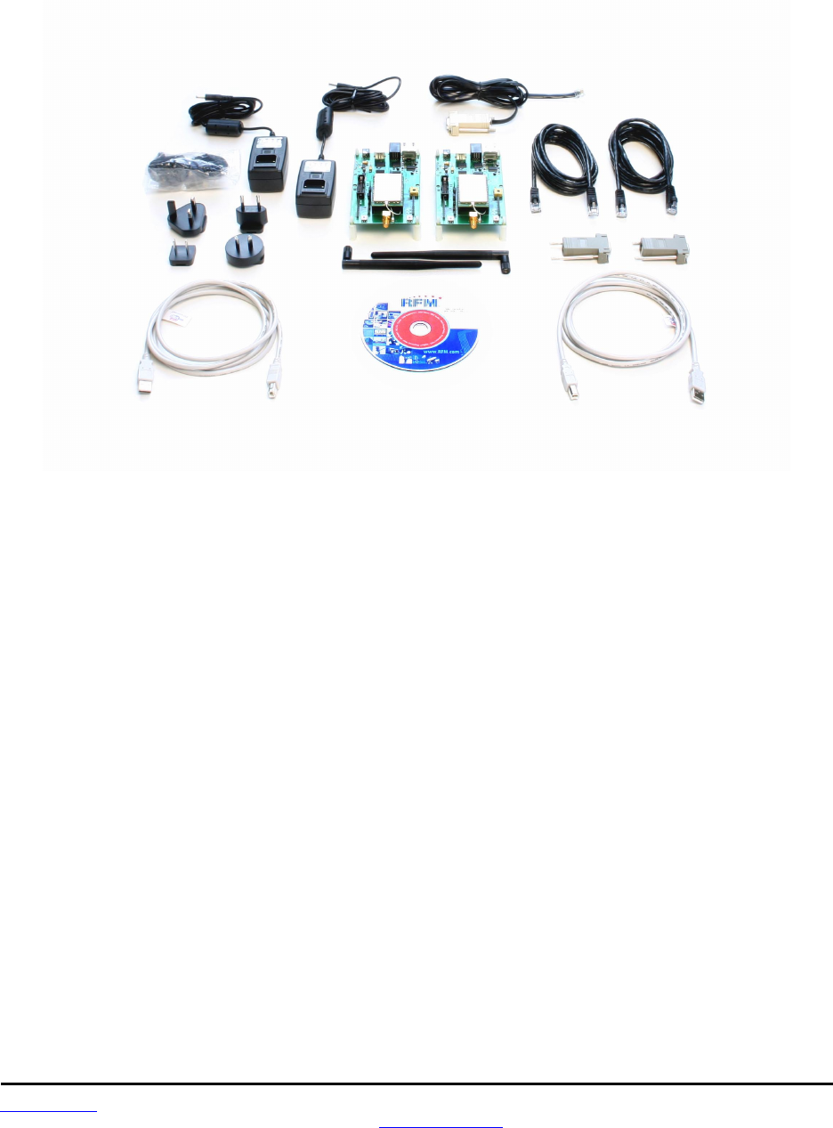
www.RFM.com Technical support +1.678.684.2000 Page 48 of 81
©2009 by RF Monolithics, Inc. E-mail: tech_sup@rfm.com DNT2400 - 08/06/09
5.0 DNT2400DK Developer’s Kit
Figure 5.0.1 shows the main contents of a DNT2400DK Developer’s kit:
Figure 5.0.1
5.1 DNT2400DK Kit Contents
• Two DNT2400P radios installed in DNT2400 interface boards (labeled Base and Remote)
• Two 2 dBi dipole antennas with two U.FL coaxial jumper cables
• Two 9 V wall-plug power suppliers, 120/240 VAC, plus two 9 V batteries (not show above)
• Two RJ-45/DB-9F cable assemblies, one RJ-11/DB-9F cable assembly, two A/B USB cables
• One DNT2400DK documentation and software CD
5.2 Additional Items Needed
To operate the kit, the following additional items are needed:
• One PC with Microsoft Windows XP or Vista Operating System. The PC must be equipped with a
USB port or a serial port capable of operation at 9.6 kb/s.
5.3 Developer’s Kit Operational Notes:
DNT2400DK kits are preconfigured to run at a 500 kb/s RF data rate with 1 mW of RF transmitter power.
Due to the high sensitivity of the DNT2400 radio module which provides its exceptional range, if the RF
transmit power is increased from the default 1 mW, the DNT2400 nodes must be separated by a
minimum of 6 feet for 10 mW or 25 feet at 63 mW in order to reliably link.
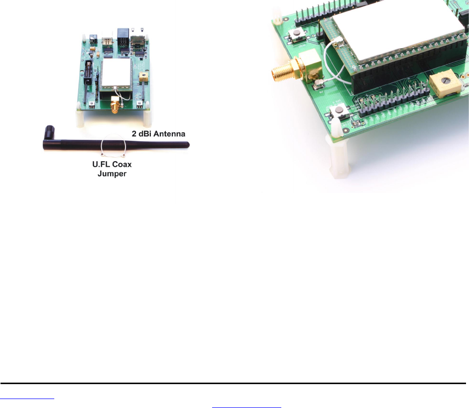
www.RFM.com Technical support +1.678.684.2000 Page 49 of 81
©2009 by RF Monolithics, Inc. E-mail: tech_sup@rfm.com DNT2400 - 08/06/09
5.4 Developer’s Kit Default Operating Configuration
The default operating configuration of the DNT2400DK developer’s kit is TDMA Mode 2, point-to-point,
with transparent serial data at 9.6 kb/s, 8N1. One DNT2400P is preconfigured as a base and the other as
a remote. Labels on the bottom of the interface boards specify Base or Remote. The defaults can be
overridden to test other operating configurations using the DNT Demo utility discussed in Section 5.5. The
default RF power setting is 0 dBm (1 mW), which is suitable for operation at a spacing of about 1.5 to 2 m
(4 to 6 ft). The RF power level should be set higher as needed for longer range operation. Note that
setting the RF power to a high level when doing testing at 2 m can overload the DNT2400P receiver and
cause erratic operation. See Section 5.3.
5.5 Developer’s Kit Hardware Assembly
Observe ESD precautions when handling the kit circuit boards. The components that make up a devel-
opment board are shown in Figure 5.5.1, and are shipped with the DNT2400P radios and U.FL coax
jumper cables installed in the interface board. If a DNT2400P radio and/or the U.FL jumper cable has
been unplugged after receipt, confirm the DNT2400P is correctly plugged into its interface board with the
radio oriented so that its U.FL connector is next to the U.FL connector on the interface board, as shown in
Figure 5.5.2. Also check the radio’s alignment in the socket on the interface board. No pins should be
hanging out over the ends of the connector. Next, install the dipole antennas.
Figure 5.5.1 Figure 5.5.2
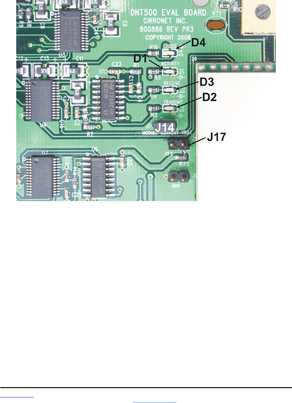
www.RFM.com Technical support +1.678.684.2000 Page 50 of 81
©2009 by RF Monolithics, Inc. E-mail: tech_sup@rfm.com DNT2400 - 08/06/09
As shown in Figure 5.5.3, there is a jumper on pins J14. This jumper can be removed and a current meter
connected across J14 to measure just the DNT2400’s current consumption during operation.
Figure 5.5.3
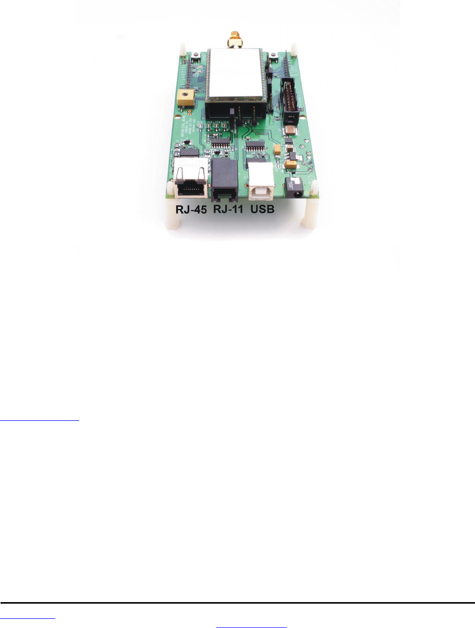
www.RFM.com Technical support +1.678.684.2000 Page 51 of 81
©2009 by RF Monolithics, Inc. E-mail: tech_sup@rfm.com DNT2400 - 08/06/09
There are three serial connectors on the interface boards, as shown in Figure 5.5.4. The RJ-45 connector
provides a high-speed RS232 interface to the DNT2400P’s main serial port. The USB connector provides
an optional interface to the radio’s main serial port. The RJ-11 connector provides a high-speed RS232
interface to the radio’s diagnostic port. The DNT Demo utility program runs on the radio’s main port.
Figure 5.5.4
Many desktop PCs have a built-in serial port capable of operation at 9.6 kb/s. The kit can be run satisfac-
torily at the 9.6 kb/s data rate, but not at its fastest throughput. Use the RJ-45 to DB-9F cable assemblies
for serial port operation.
Optionally, the kit development boards can be run from USB ports. Plugging in the USB cable automati-
cally switches operation from the RJ-45 connector. The USB interface is based on an FT232RL serial-to-
USB converter IC manufactured by FTDI. The FT232RL driver files are located in the i386 and AMD64
folders on the kit CD, and the latest version of the drivers can downloaded from the FTDI website,
www.ftdichip.com. The drivers create a virtual COM port on the PC. Power the Base using one of the
supplied wall-plug power supplies. Next connect the Base to the PC with a USB cable. The PC will find
the new USB hardware and open a driver installation dialog box. Enter the letter of the drive holding the
kit CD and click Continue. The installation dialog will run twice to complete the FT232R driver installation.
5.6 DNT Demo Utility Program
The DNT Demo utility requires only one PC for initial kit operation and sensor applications (ADC, PWM
and digital I/O). Two serial/USB ports are required for bidirectional serial communications. Section 5.6.1
below covers using the DNT Demo utility for initial kit operation and familiarization. Section 5.6.2 covers
serial message communication and radio configuration.
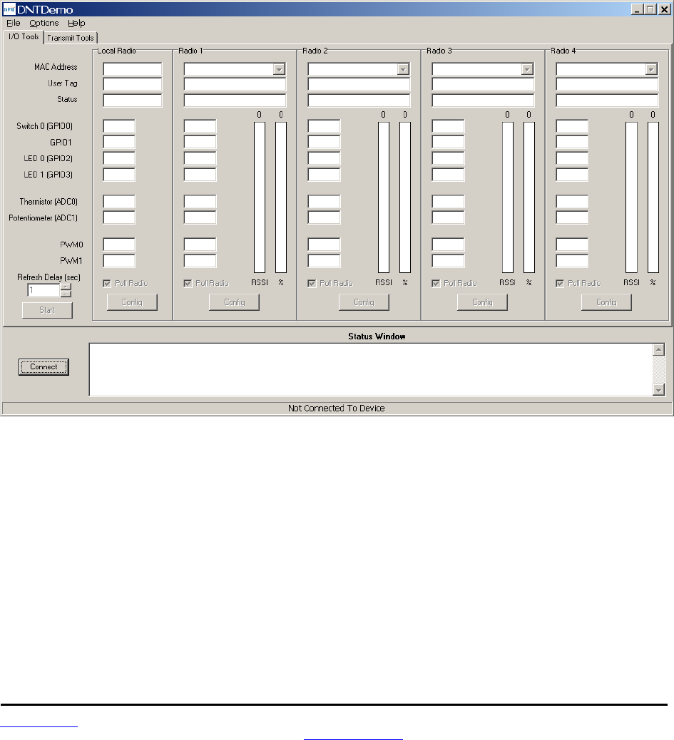
www.RFM.com Technical support +1.678.684.2000 Page 52 of 81
©2009 by RF Monolithics, Inc. E-mail: tech_sup@rfm.com DNT2400 - 08/06/09
5.6.1 Initial Kit Operation
Create a file folder on the PC and copy the contents of the kit CD into the folder.
The DNT Demo utility program runs on the radio’s main port. The preferred PC interface is a serial port
capable of operating at 9.6 kb/s or faster. As discussed above, the USB interface can also be used,
Connect the Base to the PC and power up the Base and the Remote development boards with the
supplied wall-plug power supplies.
The DNT Demo utility program is located in the PC Programs folder. The DNT Demo requires no
installation and can be simply copied to the PC and run. Start the DNT Demo on the PC. The start-up
window is shown in Figure 5.6.1.1.
Figure 5.6.1.1
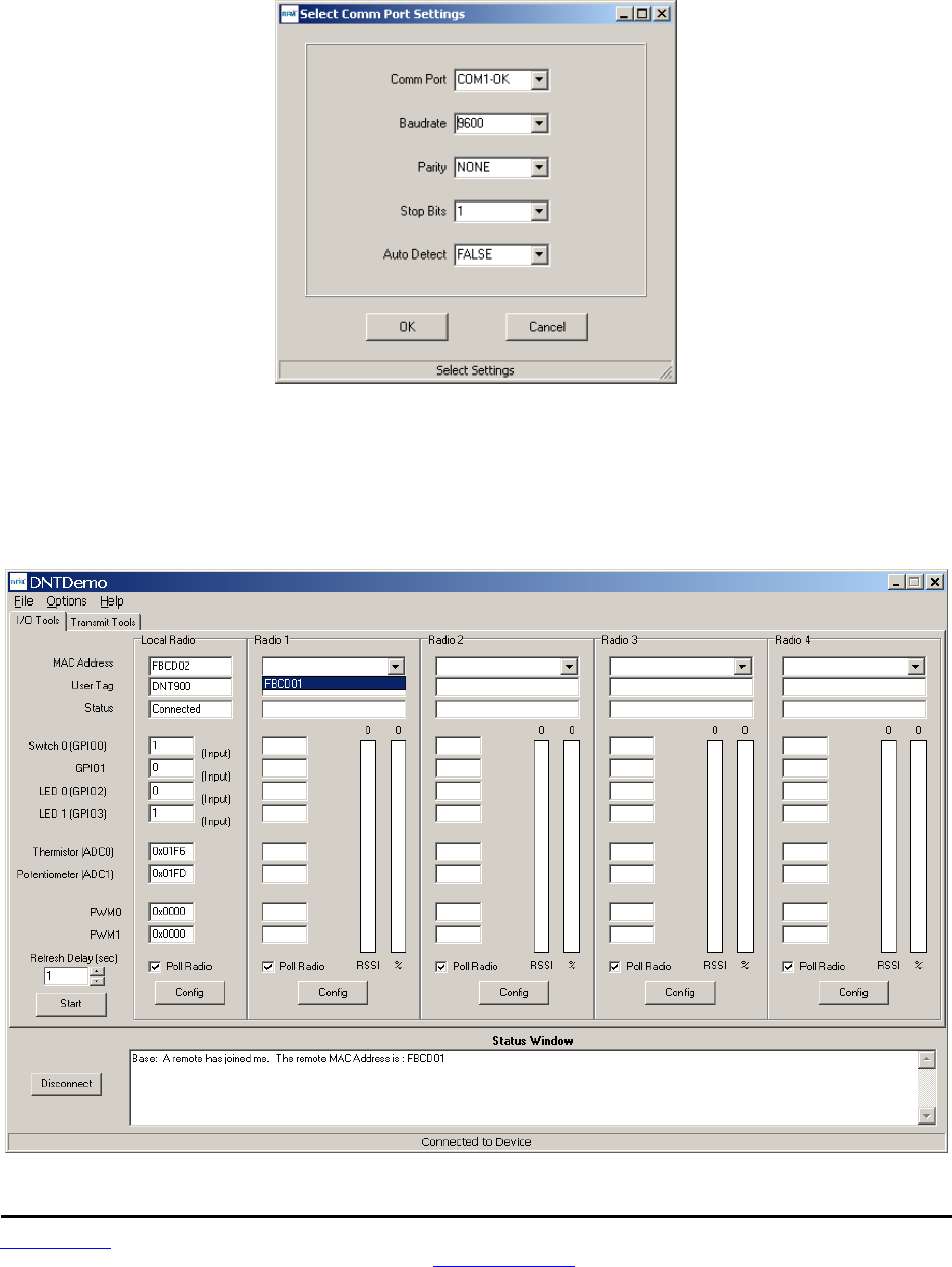
www.RFM.com Technical support +1.678.684.2000 Page 53 of 81
©2009 by RF Monolithics, Inc. E-mail: tech_sup@rfm.com DNT2400 - 08/06/09
Click on Connect to open the Select Comm Port Settings dialog box, as shown in Figure 5.6.1.2. Set the
baud rate to 9600 (9.6 kb/s). Set the CommPort to match the serial port connected to the Base, either the
hardware port or the USB virtual serial port. Then click OK to activate the serial connection.
Figure 5.6.1.2
At this point the Demo will collect data from the Base, filling in data in the Local Radio column on the
Demo window as shown in Figure 5.6.1.3. The Status Window should also show that the Remote has
joined the Base. Click on the drop-down box at the top of the Radio 1 column and select the MAC
Address for the Remote. Next press the Start button using the default 1 second Refresh Delay.
Figure 5.6.1.3
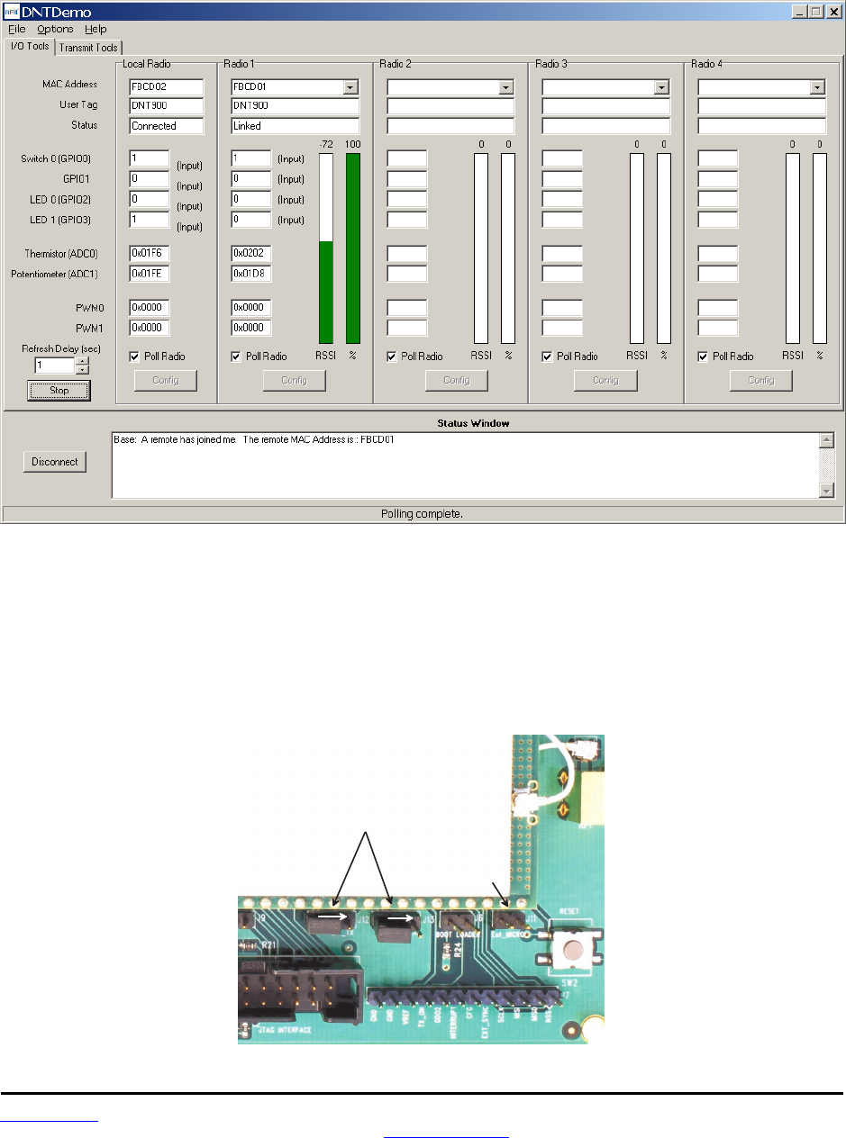
www.RFM.com Technical support +1.678.684.2000 Page 54 of 81
©2009 by RF Monolithics, Inc. E-mail: tech_sup@rfm.com DNT2400 - 08/06/09
The Demo will display updated data on the Remote in the Radio 1 column, including bar graphs of RSSI
signal strength in dBm and percent packet success rate, as shown in Figure 5.6.1.4. Adjusting the large
pot on the Remote can be observed on the Potentiometer (ADC1) row.
Figure 5.6.1.4
To perform serial data loop back testing with the kit, move the two jumpers on the Remote board labeled
Ext_TX and Ext_RX to connect the center and right header pins. This disconnects the module's TX and
RX pins from the USB and RS-232C circuits. Use a banana clip or other short jumper to connect together
the two pins on the header labeled Ext_MICRO. See Figure 5.6.1.5. Attempting loop back testing by
connecting Pins 2 and 3 of the DB9 serial connector can cause erratic behavior due to noise coupling
from the serial TX and RX lines into the weakly pulled up flow control lines on the board.
M o v e E x t _ T X
a n d E x t _ R X
J u m p e r s t o R i g h t
I n s t a l l J u m p e r
o n E x t _ M I C R O
Figure 5.6.1.5
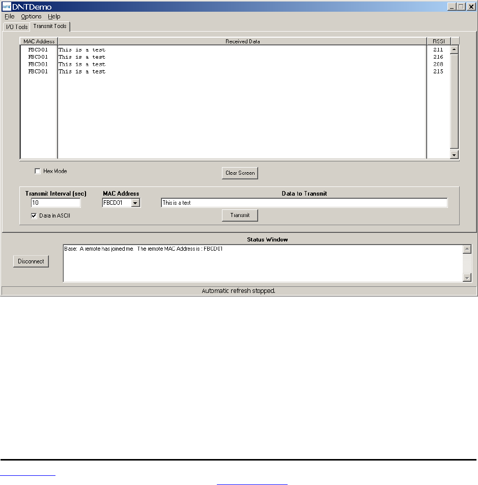
www.RFM.com Technical support +1.678.684.2000 Page 55 of 81
©2009 by RF Monolithics, Inc. E-mail: tech_sup@rfm.com DNT2400 - 08/06/09
In order to turn off the DCD LED (D4) on the development board in sleep mode, the GPIO_ SleepState
parameter in the DNT2400P has been set to 0xC0 rather than the factory default value of 0x00. If the
DNT2400P is reset to its factory defaults, the DCD LED with remain on in sleep mode until the GPIO_
SleepState is set to 0xC0. See Section 4.2.7 for additional information on the GPIO_SleepState
parameter.
If any difficulty is encountered in setting up the DNT2400DK development kit, contact RFM’s module
technical support group. The phone number is +1.678.684.2000. Phone support is available from 8:30 AM
to 5:30 PM US Eastern Time Zone, Monday through Friday. The E-mail address is tech_sup@rfm.com.
5.6.2 Serial Communication and Radio Configuration
Connect PCs to both the Base and the Remote for serial communication testing. Click the Stop button
under the Refresh Delay label on the I/O Tools tab and move to the Transmit Tools tab, as shown in
Figure 5.6.2.1.
Figure 5.6.2.1
Pressing the Transmit button on this screen sends the message in the Data to Transmit text box to the
selected MAC Address. Data sent to the local radio is displayed in the Received Data text box. Received
data can be displayed as ASCII (default) or in Hexadecimal format by checking the Hex Mode check box.
When the Transmit Interval is set to zero, Data to Transmit is sent once when the Transmit button is
clicked. When the Transmit Interval is set to a positive number, Pressing the Transmit button once will
cause a transmission each transmit interval (seconds) until the button is pressed again.
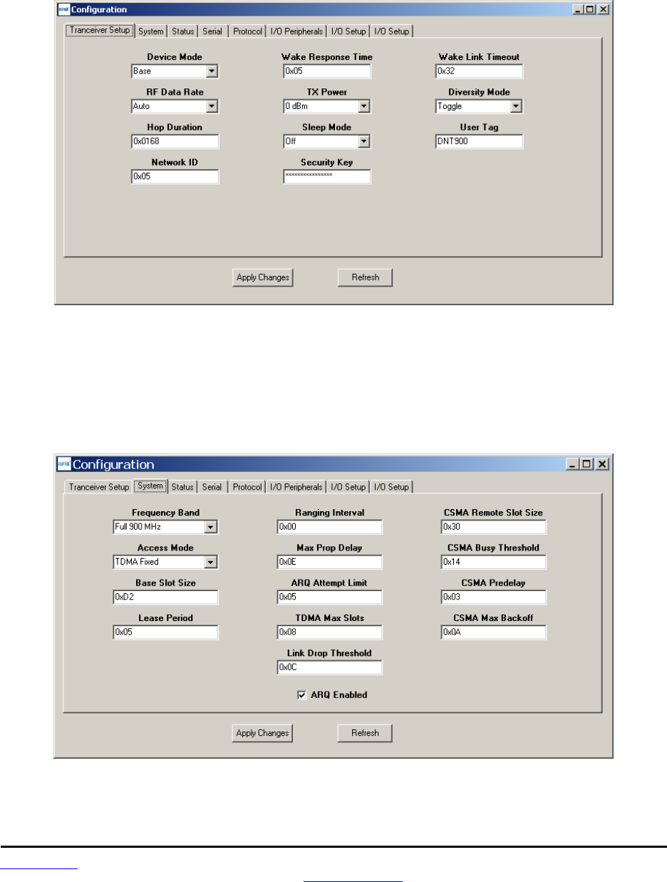
www.RFM.com Technical support +1.678.684.2000 Page 56 of 81
©2009 by RF Monolithics, Inc. E-mail: tech_sup@rfm.com DNT2400 - 08/06/09
Returning to the I/O Tools tab, the multi-tab Configuration window for each radio can be accessed by
clicking on its Config button. The data presented on the first six tabs corresponds to configuration register
Banks 0 through 5 as discussed in Section 4.2 above, with the data on the last two tabs corresponding to
configuration register Bank 6.
Figure 5.6.2.2
The Transceiver Setup Tab is shown in Figure 5.6.2.2 and corresponds to Bank 0. The current values of
each Bank 0 parameter are displayed and can be updated by selecting from the drop-down menus or
entering data from the keyboard, and then pressing the Apply Changes button. Note that data is
displayed and entered in Big-Endian order. The Demo automatically reorders multi-byte data to and from
Little-Endian order when building or interpreting messages.
Figure 5.6.2.3
Figure 5.6.2.3 shows the System tab contents, corresponding to Bank 1. The current values of each
parameter are displayed and can be updated by selecting from the drop-down menus or entering data
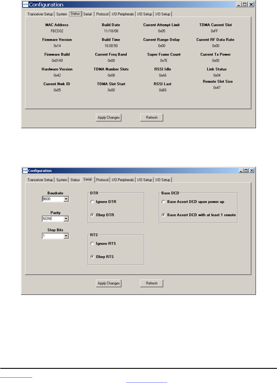
www.RFM.com Technical support +1.678.684.2000 Page 57 of 81
©2009 by RF Monolithics, Inc. E-mail: tech_sup@rfm.com DNT2400 - 08/06/09
from the keyboard, and then pressing the Apply Changes button. Note that Bank 1 holds configuration
parameters for the base only except for ARQ_Mode, which applies to both the base and the remotes.
Figure 5.6.2.4
Figure 5.6.2.4 shows the Status tab contents, corresponding to Bank 2. Note the Status tab contains
read-only parameters.
Figure 5.6.2.5
Figure 5.6.2.5 shows the Serial tab contents corresponding to Bank 3. The values shown are the defaults
for serial port operation.
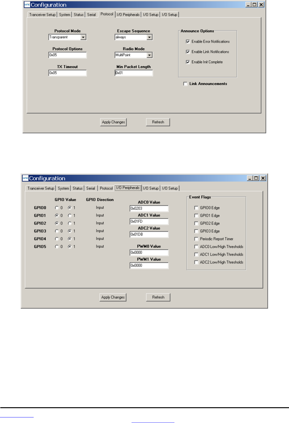
www.RFM.com Technical support +1.678.684.2000 Page 58 of 81
©2009 by RF Monolithics, Inc. E-mail: tech_sup@rfm.com DNT2400 - 08/06/09
Figure 5.6.2.6
Figure 5.6.2.6 shows the Protocol tab contents, corresponding to Bank 4. Transparent data serial com-
munication is currently chosen.
Figure 5.6.2.7
Figure 5.6.2.7 shows the I/O Peripherals tab contents, corresponding to Bank 5. GPIO ports 1, 3, 4 and 5
are logic high, GPIO port 1 and 2 are logic low. The 10-bit ADC input readings and PWM output settings
are given in Big-Endian byte order. Event flags are presented on the right side of the window.
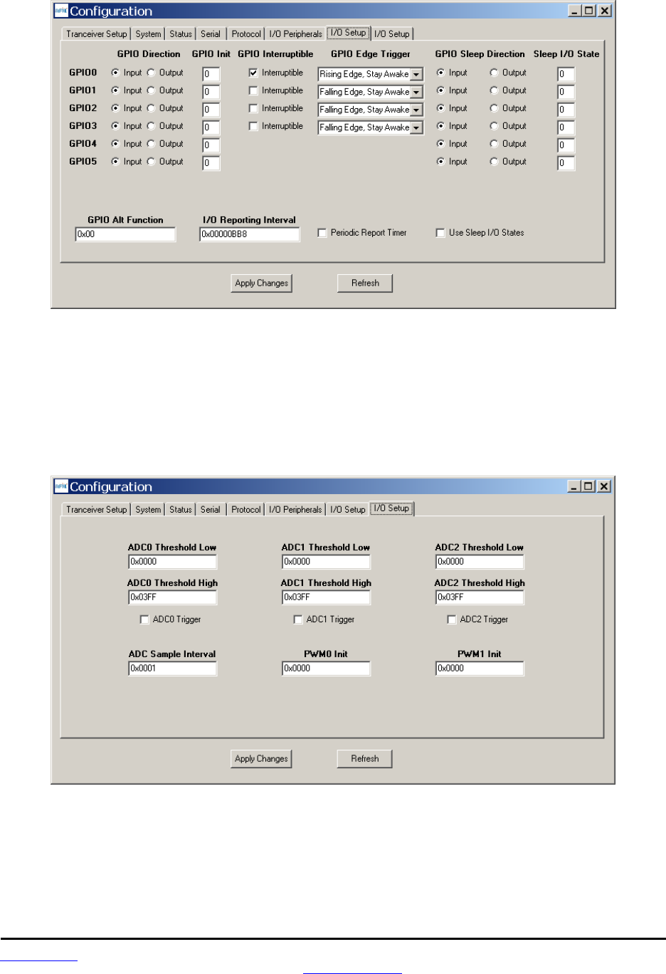
www.RFM.com Technical support +1.678.684.2000 Page 59 of 81
©2009 by RF Monolithics, Inc. E-mail: tech_sup@rfm.com DNT2400 - 08/06/09
Figure 5.6.2.8
Figure 5.6.2.8 shows the first I/O Setup tab contents, corresponding to Bank 6 GPIO parameters. This tab
allows the direction of the GPIO ports to be set both for active and sleep modes, and in the case of GPIO
outputs, the initial power up states and sleep mode states to be set. When GPIO ports 0 - 3 are config-
ured as inputs, event interrupts can be set for them with check boxes. The type of interrupt trigger is
selected from the drop-down boxes to the right of the check boxes. GPIO alternate function, periodic I/O
reporting, reporting interval and enable/disable sleep I/O states can also be specified under this tab.
Figure 5.6.2.9
Figure 5.6.2.9 shows the second I/O Setup tab contents, corresponding to Bank 6 ADC input and PWM
output parameters. The ADC sampling interval, high and low thresholds for event reporting and event
reporting triggers on each ADC channel can be set, along with the start-up output values for each PWM
(DAC) channel.
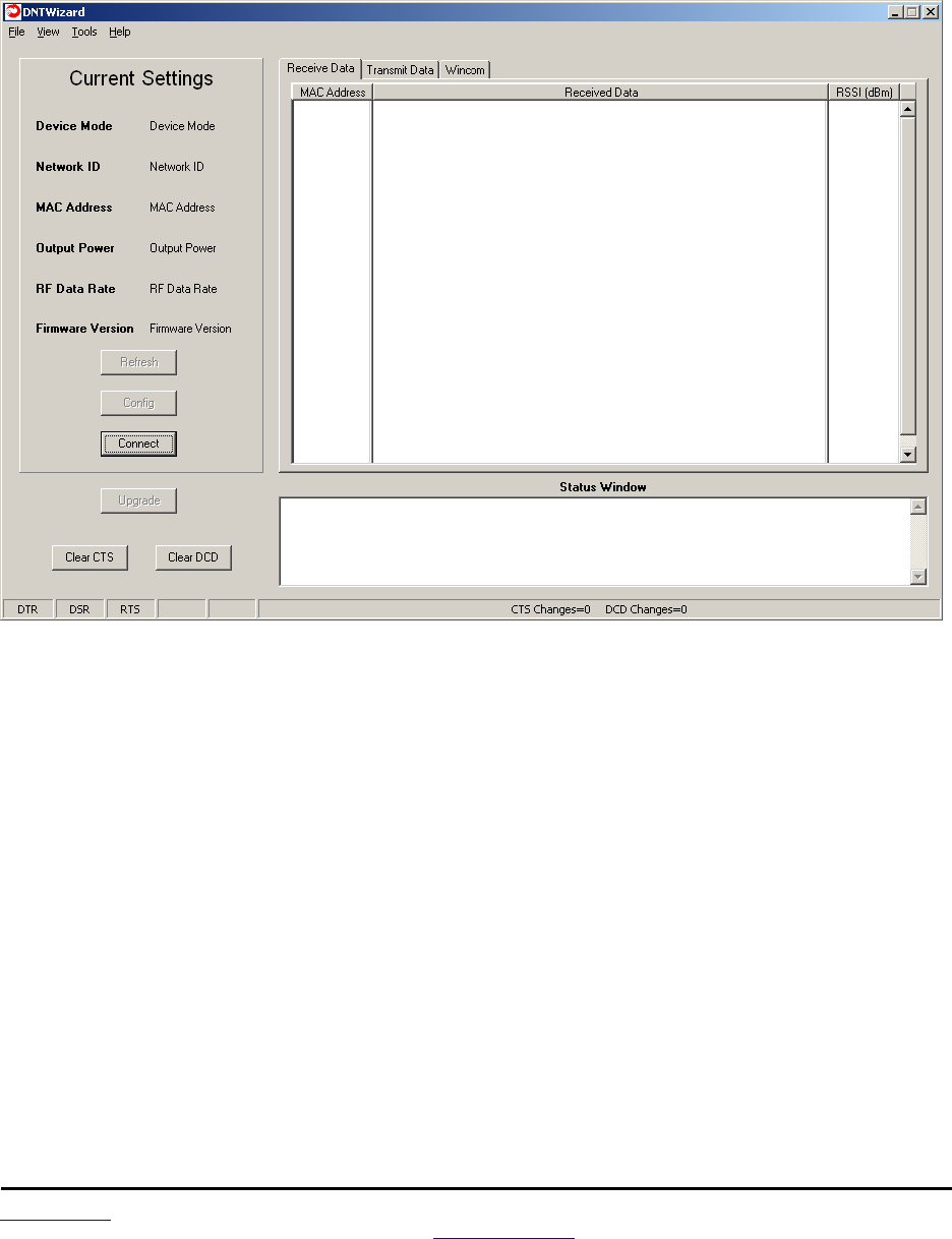
www.RFM.com Technical support +1.678.684.2000 Page 60 of 81
©2009 by RF Monolithics, Inc. E-mail: tech_sup@rfm.com DNT2400 - 08/06/09
5.7 DNT Wizard Utility Program
The DNT Wizard is a complementary program to the DNT Demo that emphasizes the details of serial
communication between a DNT2400 and its host computer. The DNT Wizard start-up window is shown in
Figure 5.7.1.
Figure 5.7.1
The DNT Wizard uses three Function keys:
F1 toggles the SLEEP/DTR input to the DNT2400 on and off. This allows the DNT2400 to be reset.
F2 toggles the RTS input to the DNT2400 on and off, providing manual flow control.
F6 toggles test transmissions on and off. The test message is “This is a test”.
The DNT Wizard also includes the ability to log messages to and from the DNT2400. This feature is
especially useful in confirming the format of protocol command and reply messages. Control of the log file
is under the View menu. Logging is enabled by default. The log file created is logfile.dat, and is in ASCII
text format. An example log is shown at the end of this section.
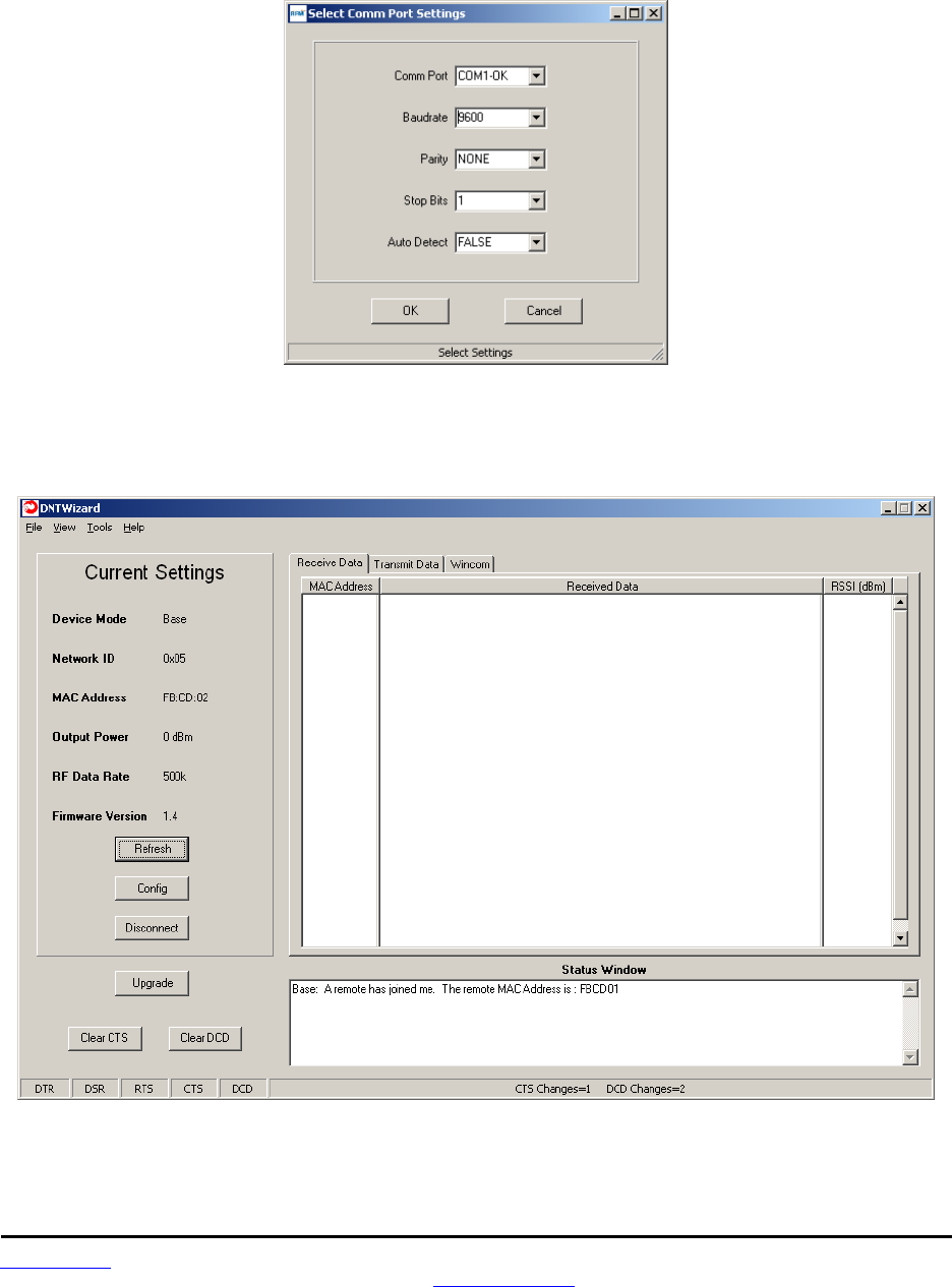
www.RFM.com Technical support +1.678.684.2000 Page 61 of 81
©2009 by RF Monolithics, Inc. E-mail: tech_sup@rfm.com DNT2400 - 08/06/09
Click on Connect to open the Select Comm Port Settings dialog box, as shown in Figure 5.7.2. Set the
baud rate to 9600 (9.6 kb/s). Set the CommPort to match the serial port connected to the Base, either the
hardware port or the USB virtual serial port. Then click OK to activate the serial connection.
Figure 5.7.2
At this point the Wizard will collect data from the Base, filling in data under Current Settings as shown in
Figure 5.7.3. The Status Window should also show that the Remote has joined the Base.
Figure 5.7.3
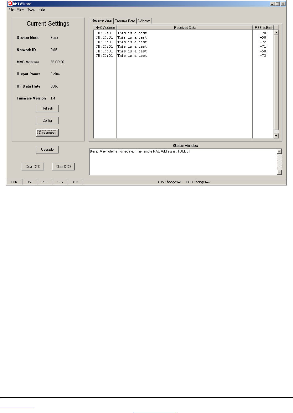
www.RFM.com Technical support +1.678.684.2000 Page 62 of 81
©2009 by RF Monolithics, Inc. E-mail: tech_sup@rfm.com DNT2400 - 08/06/09
There are three tabs on the DNT Wizard main window: Receive Data, Transmit Data and Wincom.
Figure 5.7.4
Received messages are displayed in the Receive Data tab, along with the MAC address of the sender
and the RSSI (signal strength) of the received message in dBm. See Figure 5.7.4.
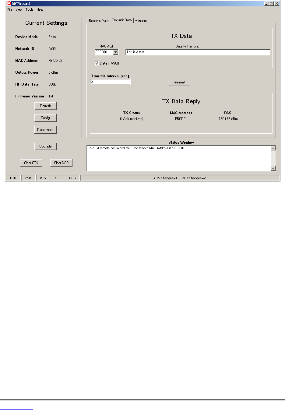
www.RFM.com Technical support +1.678.684.2000 Page 63 of 81
©2009 by RF Monolithics, Inc. E-mail: tech_sup@rfm.com DNT2400 - 08/06/09
Figure 5.7.5
The Transmit Data tab is shown in Figure 5.7.5. The message to send is input in the Data to Transmit text
box. The address to send the message can be chosen or input in the MAC Addr drop-down box. Note
that the address for the base is always 0x000000. If the Transmit Interval is set to 0, the message is sent
once each time the Transmit button is clicked. When the Transmit Interval is set to an integer greater than
zero, the message will sent at the beginning of each interval until the Stop button (was Transmit button) is
clicked. The status of each transmission is shown below TX Data Reply. Figure 5.7.5 shows that the
transmitted message was ACKed, with the received signal strength of the ACK -66 dBm.
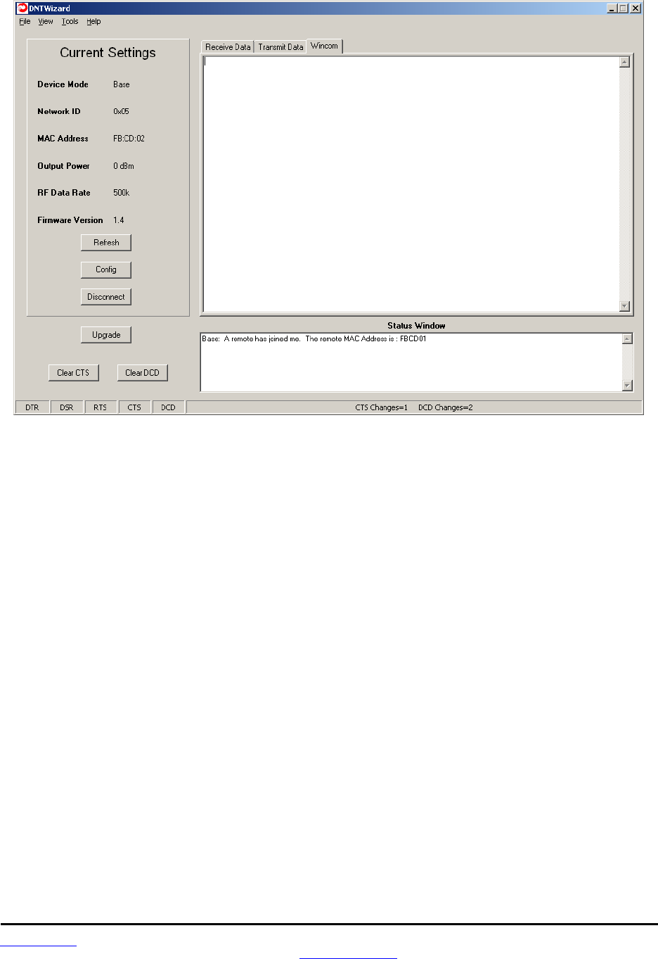
www.RFM.com Technical support +1.678.684.2000 Page 64 of 81
©2009 by RF Monolithics, Inc. E-mail: tech_sup@rfm.com DNT2400 - 08/06/09
Figure 5.7.6
As shown in Figure 5.7.6, the Wincom tab provides the basic functionality of a serial terminal program.
Messages typed in are sent, and messages received are appended to the bottom of the on-screen text.
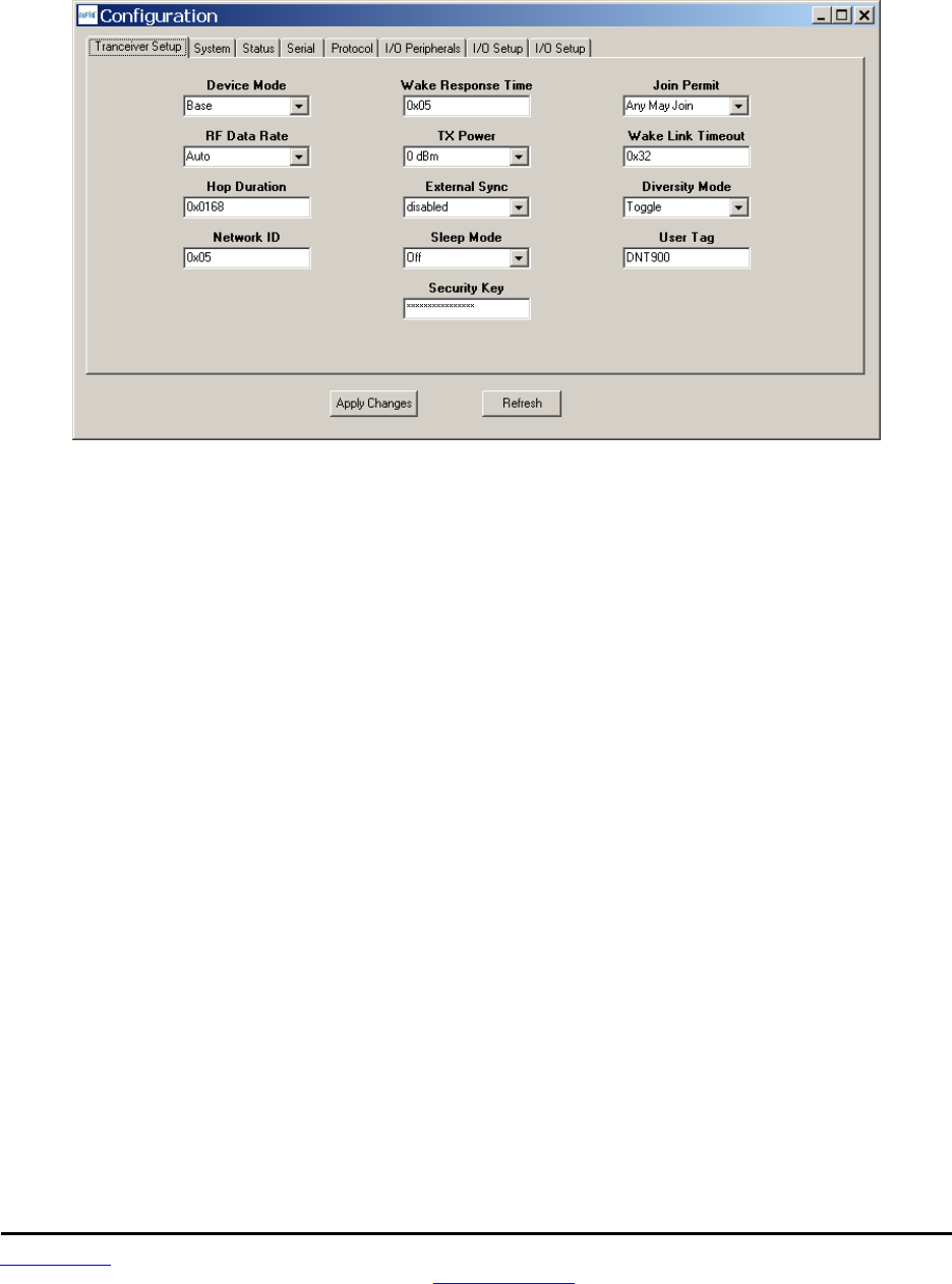
www.RFM.com Technical support +1.678.684.2000 Page 65 of 81
©2009 by RF Monolithics, Inc. E-mail: tech_sup@rfm.com DNT2400 - 08/06/09
The multi-tab Configuration window is accessed by clicking on its Config button. The data presented on
the first six tabs corresponds to configuration register Banks 0 through 5 as discussed in Section 4.2
above, with the data on the last two tabs corresponding to configuration register Bank 6.
Figure 5.7.7
The Configuration window in the DNT Wizard is identical the Configuration window in the DNT Demo. See
Figures 5.6.2.2 through 5.6.2.9 for Configuration window details.
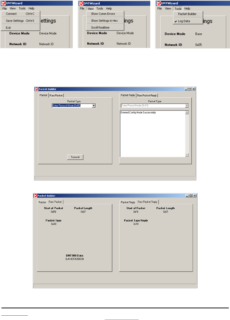
www.RFM.com Technical support +1.678.684.2000 Page 66 of 81
©2009 by RF Monolithics, Inc. E-mail: tech_sup@rfm.com DNT2400 - 08/06/09
Details of the File, View and Tools menus are shown in Figure 5.7.8.
Figure 5.7.8
The Tools menu contains two very useful items. Packet Builder opens the window shown in Figure 5.7.9.
On the left, the Packet Type drop-down box provides a selection of all packet types used in the DNT2400
protocol. On the right, the reply packet types are presented.
Figure 5.7.9
Figure 5.7.10

www.RFM.com Technical support +1.678.684.2000 Page 67 of 81
©2009 by RF Monolithics, Inc. E-mail: tech_sup@rfm.com DNT2400 - 08/06/09
Figure 5.7.10 shows the Raw Packet and Raw Packet Reply tabs. Components of the protocol messages
are shown in hexadecimal format.
Log Data controls the log file. Logging is enabled by default. The log file created is logfile.dat, and is in
ASCII text format. An example log is shown below:
New Data------------------------------------------
12/7/2008 | 7:05:39 AM
DNT Wizard Version 0.92
Sent Data : FB 07 00 44 4E 54 35 30 30 (Enter Protocol Mode)
Recv Data : FB 01 10 (Enter Protocol Mode Reply)
Sent Data : FB 04 03 00 00 2C (Get Register)
Recv Data : FB 30 13 00 00 2C 01 FF 68 01 05 2A 2A 2A 2A 2A 2A 2A 2A 2A 2A 2A 2A 2A 2A 2A 2A
00 05 32 00 00 02 02 44 4E 54 39 30 30 00 00 00 00 00 00 00 00 00 00 (Get Register Reply)
Sent Data : FB 04 03 00 01 0E (Get Register)
Recv Data : FB 12 13 00 01 0E 00 03 D2 05 00 05 08 03 0A 0E 0C 30 14 00 (Get Register Reply)
Sent Data : FB 04 03 00 02 27 (Get Register)
Recv Data : FB 2B 13 00 02 27 02 CD FB 00 05 00 00 04 47 08 00 FF 42 14 49 01 18 00 A9 00 00
05 00 31 31 2F 31 38 2F 30 38 31 36 3A 30 30 3A 35 30 (Get Register Reply)
Sent Data : FB 04 03 00 03 04 (Get Register)
Recv Data : FB 08 13 00 03 04 04 00 00 07 (Get Register Reply)
Sent Data : FB 04 03 00 04 08 (Get Register)
Recv Data : FB 0C 13 00 04 08 00 05 05 01 07 00 02 00 (Get Register Reply)
Sent Data : FB 04 03 00 05 12 (Get Register)
Recv Data : FB 16 13 00 05 12 01 00 00 00 01 01 F5 01 FD 01 DA 01 00 00 00 00 00 00 (Get
Register Reply)
Sent Data : FB 04 03 00 06 1E (Get Register)
Recv Data : FB 22 13 00 06 1E 00 00 00 01 00 00 00 00 00 00 00 01 00 00 00 FF 03 00 00 FF 03
00 00 FF 03 01 B8 0B 00 00 (Get Register Reply)
Recv Data : FB 07 27 A2 01 CD FB 01 01 (Announce)
Sent Data : FB 12 05 01 CD FB 54 68 69 73 20 69 73 20 61 20 74 65 73 74 (TX Data)
Recv Data : FB 06 15 00 01 CD FB BB (TX Data Reply)
Sent Data : FB 12 05 01 CD FB 54 68 69 73 20 69 73 20 61 20 74 65 73 74 (TX Data)
Recv Data : FB 06 15 00 01 CD FB B6 (TX Data Reply)
Sent Data : FB 12 05 01 CD FB 54 68 69 73 20 69 73 20 61 20 74 65 73 74 (TX Data)
Recv Data : FB 06 15 00 01 CD FB BA (TX Data Reply)
Sent Data : FB 12 05 01 CD FB 54 68 69 73 20 69 73 20 61 20 74 65 73 74 (TX Data)
Recv Data : FB 06 15 00 01 CD FB B8 (TX Data Reply)
Sent Data : FB 12 05 01 CD FB 54 68 69 73 20 69 73 20 61 20 74 65 73 74 (TX Data)
Recv Data : FB 06 15 00 01 CD FB B3 (TX Data Reply)
The log file is especially useful in confirming the format of specific protocol commands and replies.
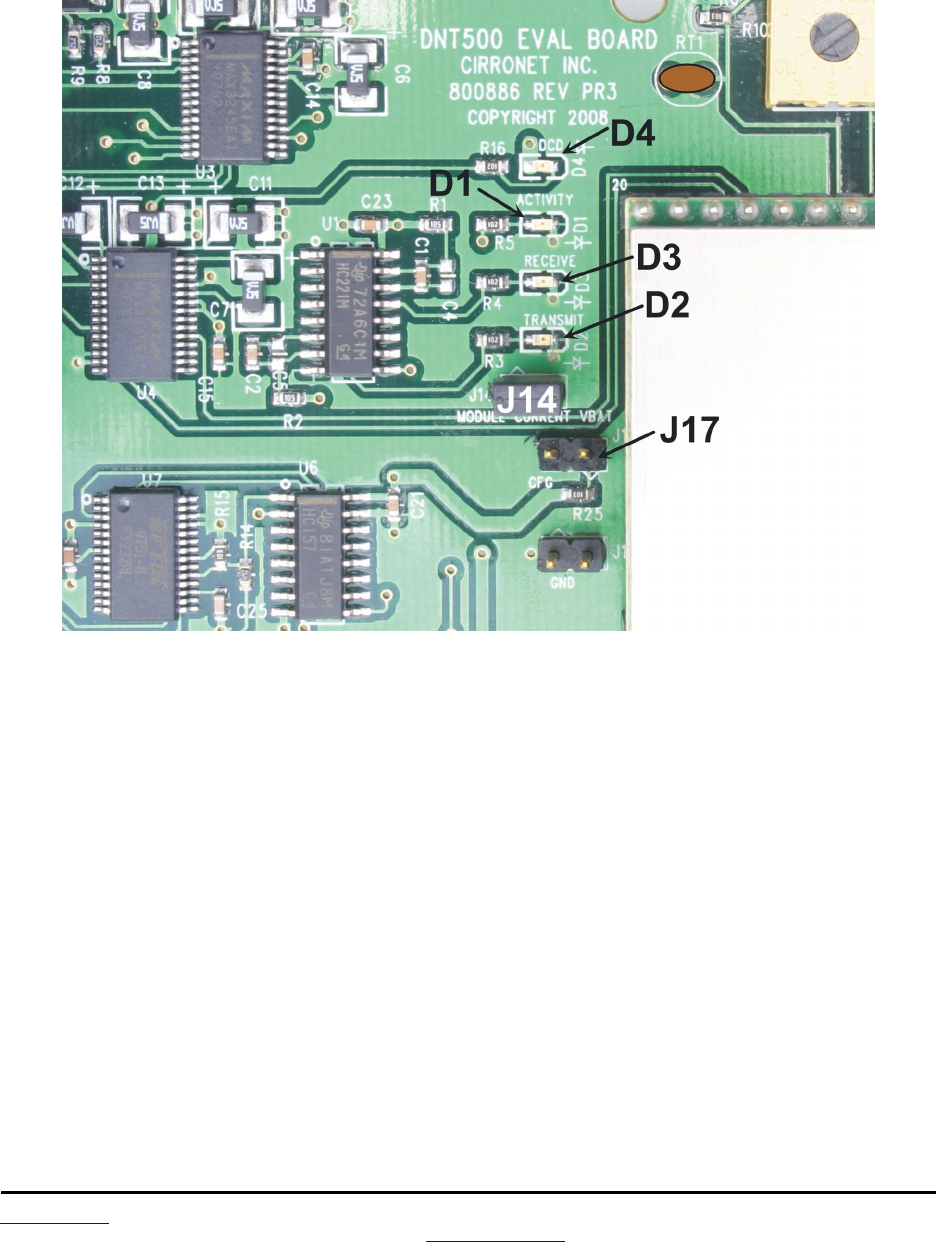
www.RFM.com Technical support +1.678.684.2000 Page 68 of 81
©2009 by RF Monolithics, Inc. E-mail: tech_sup@rfm.com DNT2400 - 08/06/09
5.8 DNT2400 Interface Board Features
The location of LEDs D1 through D4 and jumper pin sets J14 and J17 are shown in
Figure 5.8.1.
Figure 5.8.1
Amber DCD LED D4 illuminates on a remote to indicate it is registered with the base and can participate
in RF communications. DCD LED D4 illuminates on the base when one or more remotes are registered to
it, unless the base has been configured to assert DCD on power up. In this case it will be on as long as
the dev board is powered. Green Activity LED D1 illuminates when transmitting or receiving RF data. Red
Receive LED D3 illuminates when sending received data through the serial port to the PC. Green Trans-
mit LED D2 illuminates when the PC sends data through the serial port to be transmitted.
Jumper pin set J14 is provided to allow measurement of the DNT2400P current. For normal operation J14
has a shorting plug installed. Jumper pin set J17 allows the DNT2400P /CFG pin to be grounded by
installing a shorting plug. This places the DNT2400P in protocol mode.
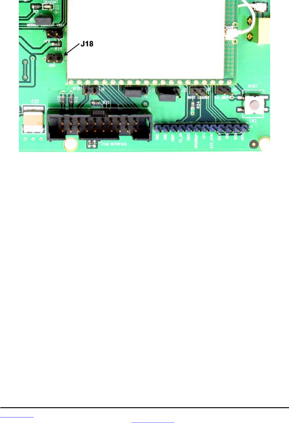
www.RFM.com Technical support +1.678.684.2000 Page 69 of 81
©2009 by RF Monolithics, Inc. E-mail: tech_sup@rfm.com DNT2400 - 08/06/09
Figure 5.8.2
Figure 5.8.2 shows the connectors to the right of the DNT2400P mounting socket. Jumper pin set J9
allow the DNT2400P reset line to be routed to the JTAG interface connector J10. J18 allows the
DNT2400P reset line to be grounded. Note that the JTAG operation is usually limited to factory testing.
For normal operation pin sets J9 and J18 should not have a shorting block installed. Jumper pin sets J12
and J13 normally have shorting plugs installed as shown in Figure 5.8.2, which connects the DNT2400P
RADIO_TXD and RADIO_RXD pins to the respective serial data lines on the evaluation board. It is possi-
ble to connect directly to RADIO_TXD and RADIO_RXD by moving the jumpers over. In this case, J11-1
is the input for transmitted data and J11-2 is the output for received data. Note this a 3 V logic interface.
Placing a shorting plug on jumper pin set J6 allows the DNT2400P to be powered up in boot loader mode.
This is used for factory code loads and functional testing. The DNT2400 has its own boot loader utility
that allows the protocol firmware to be installed with a terminal program that supports YMODEM. Pin strip
J7 provides access to various DNT2400 pins as shown on the silkscreen. Pressing switch SW2 will reset
the DNT2400P.
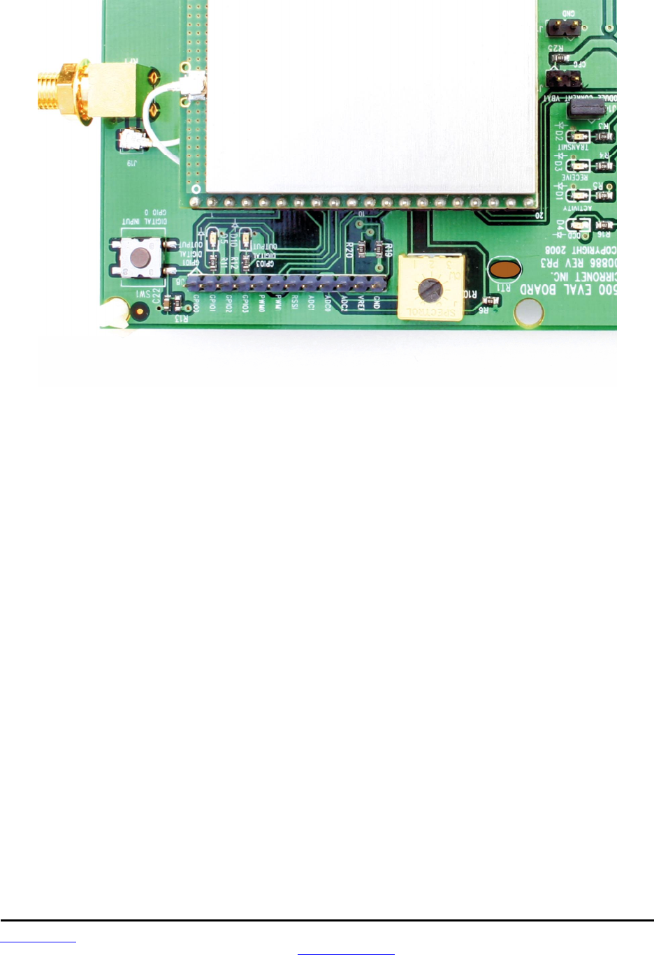
www.RFM.com Technical support +1.678.684.2000 Page 70 of 81
©2009 by RF Monolithics, Inc. E-mail: tech_sup@rfm.com DNT2400 - 08/06/09
Figure 5.8.3
Figure 5.8.3 shows the connectors to the left of the DNT2400P mounting socket. Pressing switch SW2
switches GPIO0 from logic high to logic low. Pin strip J8 provides access to various DNT2400 pins as
shown on the silkscreen. The wiper of pot R10 drives the input of ADC1. Clockwise rotation of the pot
wiper increases the voltage. Thermistor RT1 is part of a voltage divider that drives ADC0. LED D5 illumi-
nates when GPIO1 is set as a logic high output. LED D10 illuminates when GPIO3 is set as a logic high.
The DNT2400P interface board includes a 5 V regulator to regulate the input from the 9 V wall-plug power
supply. Note: do not attempt to use the 9 V wall-plug power supply to power the DNT2400P directly. The
maximum allowed voltage input to the DNT2400P is 5.5 V.

www.RFM.com Technical support +1.678.684.2000 Page 71 of 81
©2009 by RF Monolithics, Inc. E-mail: tech_sup@rfm.com DNT2400 - 08/06/09
6.0 Demonstration Procedure
The procedure below provides a quick demonstration of the DNT2400P using a DNT2400DK
development kit:
1. Confirm that each DNT2400P transceiver is installed correctly in an interface board, and that the
U.FL jumpers between the DNT2400P radios and the interface boards are installed. Also confirm
that a dipole antenna is installed on each interface board, and that J14 has a jumper block in-
stalled on each interface board. See Figures 5.4.1, 5.4.2 and 5.4.3 above.
2. Attach the Base (see label on bottom of interface board) to a computer with the DNT Demo
program installed.
3. Place the transceiver/interface boards at least 6 feet (two meters) apart.
4. Start the DNT Demo program.
5. Click the Connect button on the Demo window. This will open a serial port setup dialog box. Set
the baud rate to 9600 (9.6 kb/s) and select the COM port where the Base is connected.
6. At this point the Demo will collect data from the Base, filling in data in the Local Radio column on
the Demo window. The Status Window should also show that the Remote has joined the Base.
7. Click on the drop-down box at the top of the Radio 1 column and select the MAC Address for the
Remote. Next press the Start button using the default 1 s Refresh Delay.
8. The Demo will display updated data on the Remote in the Radio 1 column, including bar graphs
of RSSI signal strength in dBm and percent packet success rate. Adjusting the large pot on the
Remote can be observed on the Potentiometer (ADC1) row.

www.RFM.com Technical support +1.678.684.2000 Page 72 of 81
©2009 by RF Monolithics, Inc. E-mail: tech_sup@rfm.com DNT2400 - 08/06/09
7.0 Troubleshooting
DNT2400 not responding - make sure SLEEP/DTR is not asserted (logic low) to bring the radio out of
sleep mode.
Can not enter protocol mode - make sure the host data rate is correct. The DNT2400 defaults to 9.6 kb/s.
If using the EnterProtocolMode command, send the complete protocol format for this command.
A remote never detects carrier (DCD) - check that the base is running, and that the remote InitialNwkID
parameter is the same as the base, or is set to 0xFF. If a remote is operating near the base (less than 6 ft
or 2 m), be sure the transmitter power setting on both the base and remote is set to 1 mW. If the remote is
operating far from the base, be sure the transmitter power setting on the base and remote is adequate for
communication. Also make sure that the security keys are the same.
Carrier is detected, but no data appears to be received - make sure that RTS is asserted to enable re-
ceive character flow. Make sure the RF transmit power is not on a high settings if the nodes are close
together.
Range is extremely limited - this is usually a sign of a poor antenna connection or the wrong antenna.
Check that the antenna is firmly connected. If possible, remove any obstructions near the antenna.
Transmitting terminal flashes (drops) CTS occasionally - this indicates that the transmit buffer is filling up.
This most often is caused by using a higher serial port data rate than RF data rate. Adjusting the protocol
parameters may increase the network efficiency.
7.1 Diagnostic Port Commands
FSTAT <option> - enables a frequency-ordered channel activity status log.
Available options are:
0 - off
1 - on
For either a base or remote, FSTAT shows the DataTx (data packet transmitted), AckRx (ACK received)
and RegRx (registration or renewal request or reply received) activity status on each frequency with
ASCII characters as follows:
‘.’ (0x2E) - no activity
‘1’ (0x31) - DataTx activity only
‘2’ (0x32) - AckRx activity only
‘3’ (0x33) - DataTx and AckRx activity
‘4’ (0x34) - RegRx activity only
‘5’ (0x35) - DataTx and RegRx activity
‘6’ (0x36) - AckRx and RegRx activity
‘7’ (0x37) - DataTx, AckRx and RegRx activity

www.RFM.com Technical support +1.678.684.2000 Page 73 of 81
©2009 by RF Monolithics, Inc. E-mail: tech_sup@rfm.com DNT2400 - 08/06/09
A sample FSTAT output for 37 channel operation is shown below. The status data is order from the
lowest operating frequency on the left to the highest operating frequency on the right. An ASCII CR-LF
terminates each line. On most frequencies, DataTx and AckRx occur on the same frequency (‘3’). Occa-
sionally there is DataTx, AckRx and RegRx activity (‘7’), DataTx only activity (‘1’), or no activity (‘.’).
333333 33333333 33333373 33333333 3333333
333333 33333333 33333333 33333333 3333333
333333 31333333 33333333 33333333 3333333
23.333 333133.3 3.333323 31333.33 333.333
333333 23333331 33313333 33333333 23.3333
INSTR <option>
Available options are:
0 - off
1 - on
For either a base or a remote, INSTR streams instrumentation packets including a time stamp and seven
data values. The time stamp is a string of four characters. The first three characters are ASCII represen-
tations of hexadecimal numbers. The fourth character is a ‘>’ character. Each time stamp count is 100 µs.
The time stamp rolls over to 0x000 after count 0xCE5. The content of the seven data values are detailed
below. ASCII representations of the hexadecimal value of each byte are output, separated by space
characters:
Byte 0: current channel, 0 to 36
Byte 1: same data as FSTAT 1, except no activity is 0x30
Byte 2: RSSI_Last, RSSI of last RF packet received in dBm, 8-bit signed value
Byte 3: RSSI_Idle, most recent RSSI value on a channel with no expected activity
Byte 4: Range delay estimate, remote only, 3.1 µs/tick
Byte 5: Status bits 1
b7.. b4 - reserved
b3 - inbound data RF flow control, 1 = device has disabled RF flow
b2 - outbound data RF flow control, 1 = base has disabled RF flow
b1 - /HOST_CTS, status of CTS line, 1 = hold
b0 - /DCD, link LED on; on a remote indicates registration with base, on the base it indi-
cates at least on remote is registered (default)
Byte 6: Status bits 0
b7 - CSMA channel busy
b6 - Parser/CRC error
b5 - valid RF packet received (any type)
b4 - DataRx, data packet received
b3 - RegTx, registration or renewal request or reply transmitted
b2 - RegRx, registration or renewal request or reply received
b1 - AckRx, ACK received
b0 - DataTx, data packet transmitted

www.RFM.com Technical support +1.678.684.2000 Page 74 of 81
©2009 by RF Monolithics, Inc. E-mail: tech_sup@rfm.com DNT2400 - 08/06/09
A sample INSTR output is shown below.
896> 21 01 DA 98 00 01 01
940> 0A 03 DA 9C 00 01 23
9E2> 1D 03 DA 99 00 03 23
A8A> 1E 01 D6 9F 00 03 21
B36> 11 03 D6 99 00 03 23
Looking a the first line in detail:
896> 21 01 DA 98 00 01 01
The time stamp is 0x896>
Byte 0, 0x21, indicates the channel of operation is 33 (decimal)
Byte 1, 0x01, is the same status data as FSTAT data above. In this case, DataTx activity only.
Byte 2, 0xDA, is the last RSSI value, -38 dBm
Byte 3, 0x98, is the RSSI idle value, -100 dBm
Byte 4, 0x00, is the range delay estimate (remote only). The remote is very close to the base.
Byte 5, 0x01, provides the serial port status - /HOST_CTS is high
Byte 6, 0x01, provides the communication status - DataTx active only. Note that this byte provides addi-
tional status bytes compared to byte index 1.

www.RFM.com Technical support +1.678.684.2000 Page 75 of 81
©2009 by RF Monolithics, Inc. E-mail: tech_sup@rfm.com DNT2400 - 08/06/09
8.0 Appendices
8.1 Ordering Information
DNT2400C: transceiver module for solder-pad mounting
DNT2400P: transceiver module for pin-socket mounting
8.2 Technical Support
For DNT2400 technical support call RFM at (678) 684-2000 between the hours of 8:30 AM and 5:30 PM
Eastern Time.
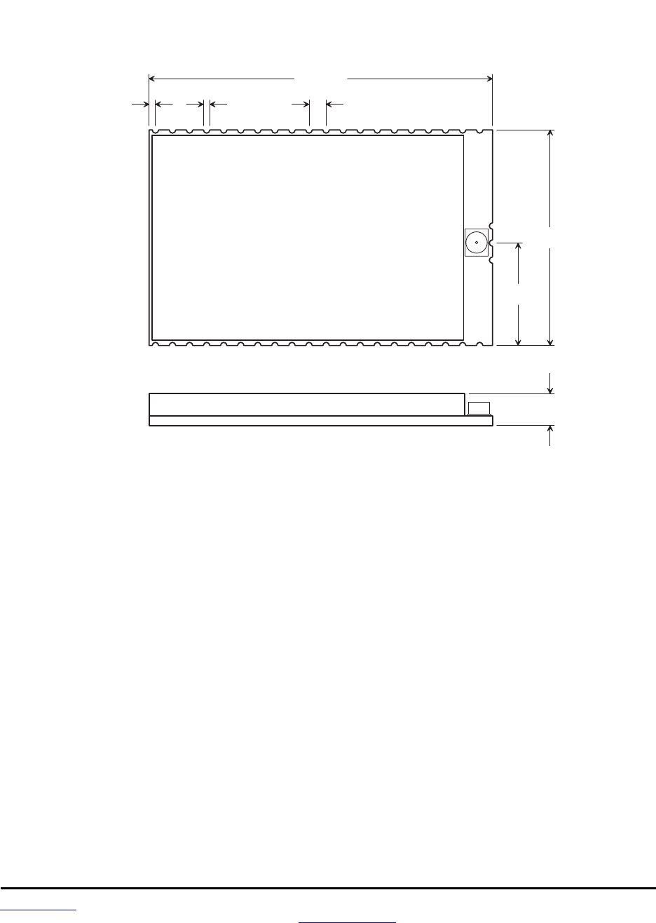
www.RFM.com Technical support +1.678.684.2000 Page 76 of 81
©2009 by RF Monolithics, Inc. E-mail: tech_sup@rfm.com DNT2400 Integration Guide - 08/06/09
8.3 DNT2400 Mechanical Specifications
D N T 2 4 0 0 C O u t l i n e a n d M o u n t i n g D i m e n s i o n s
D i m e n s i o n s i n i n c h e s
2 . 0 1 0
1 . 2 6 0
0 . 5 9 5
0 . 1 8 0
0 . 0 4 0 0 . 0 4 0 0 . 1 0 0
1
4 0
Figure 8.3.1
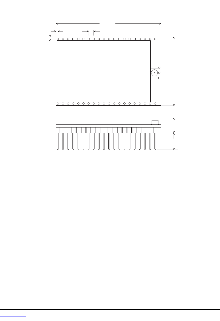
www.RFM.com Technical support +1.678.684.2000 Page 77 of 81
©2009 by RF Monolithics, Inc. E-mail: tech_sup@rfm.com DNT2400 Integration Guide - 08/06/09
D N T 2 4 0 0 P O u t l i n e a n d M o u n t i n g D i m e n s i o n s
D i m e n s i o n s i n i n c h e s
2 . 0 5 0
0 . 2 8 5
0 . 0 4 0 0 . 1 0 0
0 . 3 3 3
0 . 0 5 0
1 . 3 6 0
1
4 0
Figure 8.3.2
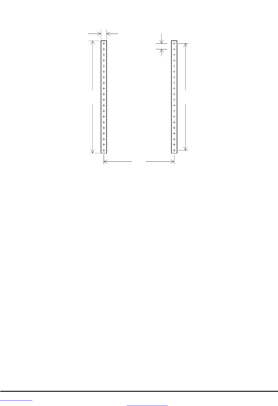
www.RFM.com Technical support +1.678.684.2000 Page 78 of 81
©2009 by RF Monolithics, Inc. E-mail: tech_sup@rfm.com DNT2400 Integration Guide - 08/06/09
1 . 9
( 4 8 . 3 )
2 . 0
( 5 0 . 8 )
0 . 1
( 2 . 5 )
D N T 2 4 0 0 P I n t e r f a c e C o n n e c t o r
P C B L a y o u t D e t a i l
0 . 1
( 2 . 5 )
C o n n e c t o r s a r e F C I E l e c t r o n i c s 7 5 9 1 5 - 4 2 0 L F o r e q u i v a l e n t
D i m e n s i o n s i n i n c h e s a n d ( m m )
1 . 2 6
M i n i m u m p l a t e d P C B
h o l e d i a m e t e r 0 . 0 3 ( 0 . 7 5 )
Figure 8.3.3
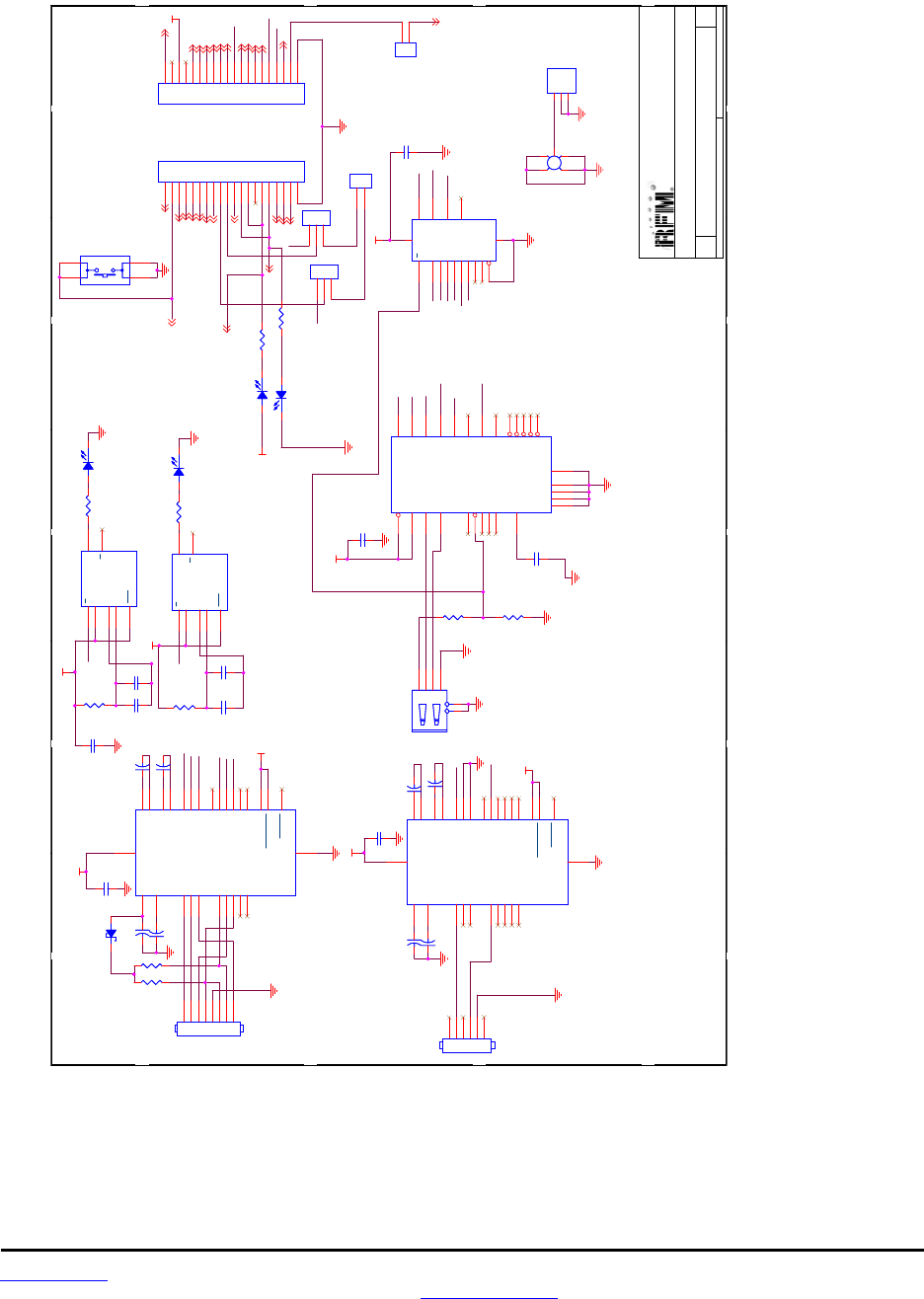
www.RFM.com Technical support +1.678.684.2000 Page 79 of 81
©2009 by RF Monolithics, Inc. E-mail: tech_sup@rfm.com DNT2400 Integration Guide - 08/06/09
8.4 DNT2400 Development Board Schematic
!"#$
!%$ &'()$*"+(),$- $.
/"$0 1$$" &2
3334
5++./#+&/-6+!*+.$-7!&*
-!6/89+&.$),$-+9+3
!"#$
!%$ &'()$*"+(),$- $.
/"$0 1$$" &2
3334
5++./#+&/-6+!*+.$-7!&*
-!6/89+&.$),$-+9+3
!"#$
!%$ &'()$*"+(),$- $.
/"$0 1$$" &2
3334
5++./#+&/-6+!*+.$-7!&*
-!6/89+&.$),$-+9+3
!
"
#$%""&'()*+#
,
-.)##%$
/-(0####110
"'21##110
",*#3##110
!45
!45
545
545
:
:
;5<
;5<
5
3
;
4
5
3
;
4
5
<
= 3
=
3
5
=
;
<
<
;
4
;
4
3
4
4
:
4
:
:(
:(
:(
:(
<5
<5
:(
:(
< ;<
< ;<
4
:;
:;
:(
:(
<5
<5
:(
:(
<5
<5
:
:
5
<
= 3
=
3
5
=
;
<
<
;
4
;
4
3
4
:(
:(
3
:;
3
:;
:(
:(
:
:
<5
<5
:(
:(
:
:
<3
<3
4
;
3
/*/7&*!'
><
/*/7&*!'
><
5
:(
5
:(
:(
:(
<
<
5
:;
5
:;
;54
;54
4
;
5
>
>
3 :(
3 :(
?"
?"
; :(
; :(
:(
:(
4 :(
4 :(
&6(#$+'(--$*"+)$/7(-$)$*"
&6(#$+'(--$*"+)$/7(-$)$*"
4
;5<
4
;5<
4
;
3
5
4
;
3
5
<4
<4
4
;
;
@
5
;
3
@ 4
;
3
@
@
@ 5
3
:
;
4
@
@
4
4
;;
4
;;
4
;
5
4
3
4
4
;54
;54
>
>
:(
:(
:
:
?"
?"
:(
:(
"6,78
5
:<<
"6,78
5
:<<
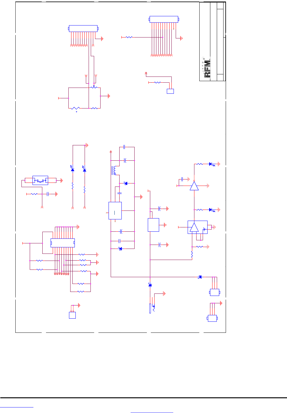
www.RFM.com Technical support +1.678.684.2000 Page 80 of 81
©2009 by RF Monolithics, Inc. E-mail: tech_sup@rfm.com DNT2400 Integration Guide - 08/06/09
!"#$
!%$ &'()$*"+(),$- $.
/"$0 1$$" &2
3334
5A+./#+&/-6+!*+.$-7!&*
-!6/89+&.$),$-+9+3
!"#$
!%$ &'()$*"+(),$- $.
/"$0 1$$" &2
3334
5A+./#+&/-6+!*+.$-7!&*
-!6/89+&.$),$-+9+3
!"#$
!%$ &'()$*"+(),$- $.
/"$0 1$$" &2
3334
5A+./#+&/-6+!*+.$-7!&*
-!6/89+&.$),$-+9+3
9!
2-!:
2-!:
2-:
-.)##%$
,
#$%""&'()*+#
/-(0####110
"'21##110
",*#3##110
*;*1
<"=<
<
<
:(
:(
4;4<:
4;4<:
4
;
!*
7B
3
(
3
(
<5
<5
5
5
>
?
,
3
3
>
?
,
3
3
4
;
3
4
4
<
+"/'C
<
+"/'C
;
;
(
(
<
<
4
3
4
3
;
5
;
5
;(
;(
<5
<5
/*/7&*!'
><
/*/7&*!'
><
5
;(
5
;(
;
;
4
4
;<:
;<:
&("
!*
&("
<5
-$$*
<5
-$$*
;
;
>
;
:;(
>
;
:;(
:
:
;
;
5
:;
5
:;
;
;
4
;
3
5
4
&&"+#&/6$-
4
&&"+#&/6$-
3
<5
$6
3
<5
$6
4
4
4 :(4 :(
3
3
3
3
4
;
3
5
+
+
3
3
55
:
:
4
4
5
5
;
:(
;
:(
:
:

www.RFM.com Technical support +1.678.684.2000 Page 81 of 81
©2009 by RF Monolithics, Inc. E-mail: tech_sup@rfm.com DNT2400 Integration Guide - 08/06/09
9.0 Warranty
Seller warrants solely to Buyer that the goods delivered hereunder shall be free from defects in materials
and workmanship, when given normal, proper and intended usage, for twelve (12) months from the date
of delivery to Buyer. Seller agrees to repair or replace at its option and without cost to Buyer all defective
goods sold hereunder, provided that Buyer has given Seller written notice of such warranty claim within
such warranty period. All goods returned to Seller for repair or replacement must be sent freight prepaid
to Seller’s plant, provided that Buyer first obtain from Seller a Return Goods Authorization before any
such return. Seller shall have no obligation to make repairs or replacements which are required by normal
wear and tear, or which result, in whole or in part, from catastrophe, fault or negligence of Buyer, or from
improper or unauthorized use of the goods, or use of the goods in a manner for which they are not de-
signed, or by causes external to the goods such as, but not limited to, power failure. No suit or action
shall be brought against Seller more than twelve (12) months after the related cause of action has oc-
curred. Buyer has not relied and shall not rely on any oral representation regarding the goods sold here-
under, and any oral representation shall not bind Seller and shall not be a part of any warranty.
THE PROVISIONS OF THE FOREGOING WARRANTY ARE IN LIEU OF ANY OTHER WARRANTY,
WHETHER EXPRESS OR IMPLIED, WRITTEN OR ORAL (INCLUDING ANY WARRANTY OR
MERCHANT ABILITY OR FITNESS FOR A PARTICULAR PURPOSE). SELLER’S LIABILITY ARISING
OUT OF THE MANUFACTURE, SALE OR SUPPLYING OF THE GOODS OR THEIR USE OR
DISPOSITION, WHETHER BASED UPON WARRANTY, CONTRACT, TORT OR OTHERWISE, SHALL
NOT EXCEED THE ACTUAL PURCHASE PRICE PAID BY BUYER FOR THE GOODS. IN NO EVENT
SHALL SELLER BE LIABLE TO BUYER OR ANY OTHER PERSON OR ENTITY FOR SPECIAL,
INCIDENTAL OR CONSEQUENTIAL DAMAGES, INCLUDING, BUT NOT LIMITED TO, LOSS OF
PROFITS, LOSS OF DATA OR LOSS OF USE DAMAGES ARISING OUT OF THE MANUFACTURE,
SALE OR SUPPLYING OF THE GOODS. THE FOREGOING WARRANTY EXTENDS TO BUYER
ONLY AND SHALL NOT BE APPLICABLE TO ANY OTHER PERSON OR ENTITY INCLUDING,
WITHOUT LIMITATION, CUSTOMERS OF BUYERS.
Part # M-2400-3002, Rev A