Murata AAF wifi module User Manual Sychip Wireless Uart User Guide V1 2
Murata Manufacturing Co., Ltd. wifi module Sychip Wireless Uart User Guide V1 2
Murata >
Contents
- 1. Manual
- 2. Users Manual
Manual

Sychip Wireless-Uart User Guide
Sychip Wireless-Uart
OEM User
Guide
Author: Lei Liu
Version: 1.2
Release Date: October 20, 2012
Sychip Wireless-Uart User Guide
CHANGE HISTORY
Version
Date
Remarks
Name
1.0
09/25/2012
Release V1.0;
Lei Liu
1.1
10/10/2012
Fixed some bugs
Jin Li
1.2
10/20/2012
Optimized the document framework
Jin Li
Sychip Wireless-Uart User Guide
www.sychip.com.cn
Page 3 of 12
2010-04
1. Brief introduction
1.1 About this document
This document describes how to use the SyChip Wireless-Uart EVK. It contains hardware installation,
tcp/udp connect, AT configuration commands.
Features:
Support IEEE802.11b/g/n Wireless Standards.
Support the wifi work at AP/STA mode.
Support WEP, WPA, WPA2 Security.
Support configurate uart interface easily.
Support TCP/IP/UDP network protocol stack.
Support send AT commands through uart to control the module.
Single +3.3v power supply.
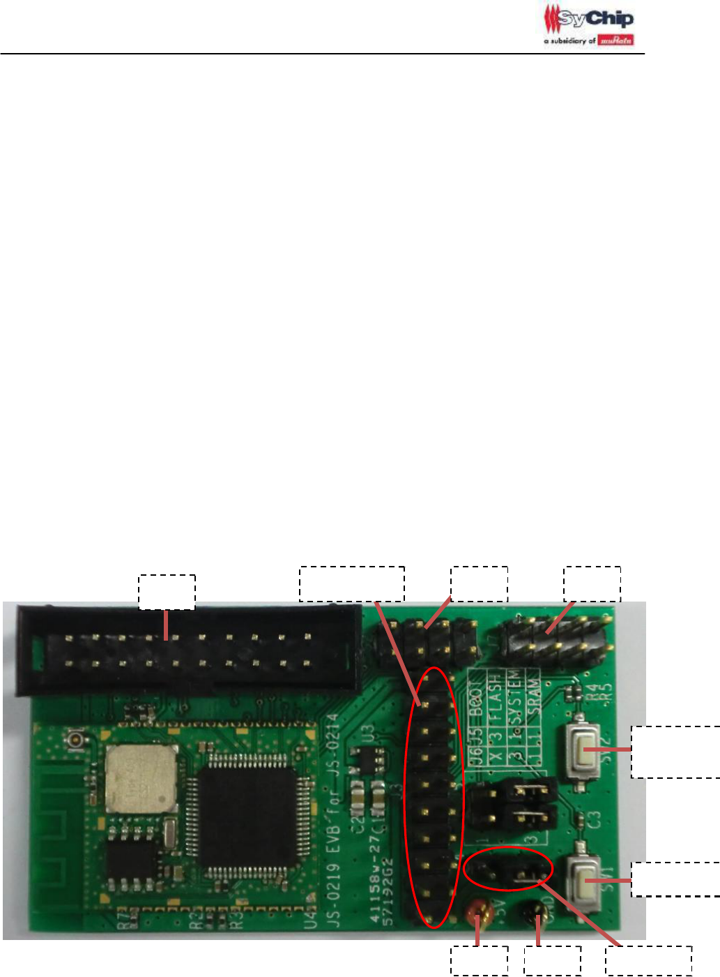
1.2 Sychip ES3 EVK Hardware Introduction
JTAG Expand pins Uart1 Uart2
Configuration
Button
Reset Button
Figure 1 Sychip Wireless-Uart EVK
+5v GND Vcc Jump
Figure 1 is Sychip Wireless-Uart EVK, it is composed of mcu, wifi, power, Uart1, Uart2, JTAG
Sychip Wireless-Uart User Guide
www.sychip.com.cn
Page 4 of 12
2010-04
interfaces etc.
(1)Power supply:
Vcc Jump(red circle marked) provides two different modes of power supply. If jump to the right pin,
the module power on through the uart. If jump to the left pin, the module power on through the +5v and
GND pin.
Note:Under normal circumstances using the uart power supply.
(2)Uart:
Uart pins function, uart1 is same to the uart2, according to the figure 1 position:
none
Rts
Rx
GND
none
Cts
Tx
Vdd_usb
(3)Button:
The EVK has 2 buttons: configuration button and reset button.
•
Reset button:
Press the reset button, the module will reset the device.
•
Configuration button:
Press the Configuration button for two or three seconds, press the reset button at the same time, the
module into configuration function, customers can configurate all parameters through AT
commands.
(4)Jtag:
The jtag’s function is download the code and debug.
(5)Expand pins:
The expand pins is reserved for expansion functions.
Sychip Wireless-Uart User Guide
www.sychip.com.cn
Page 5 of 12
2. Wireless-Uart EVK Operation
2.1 Hardware installation
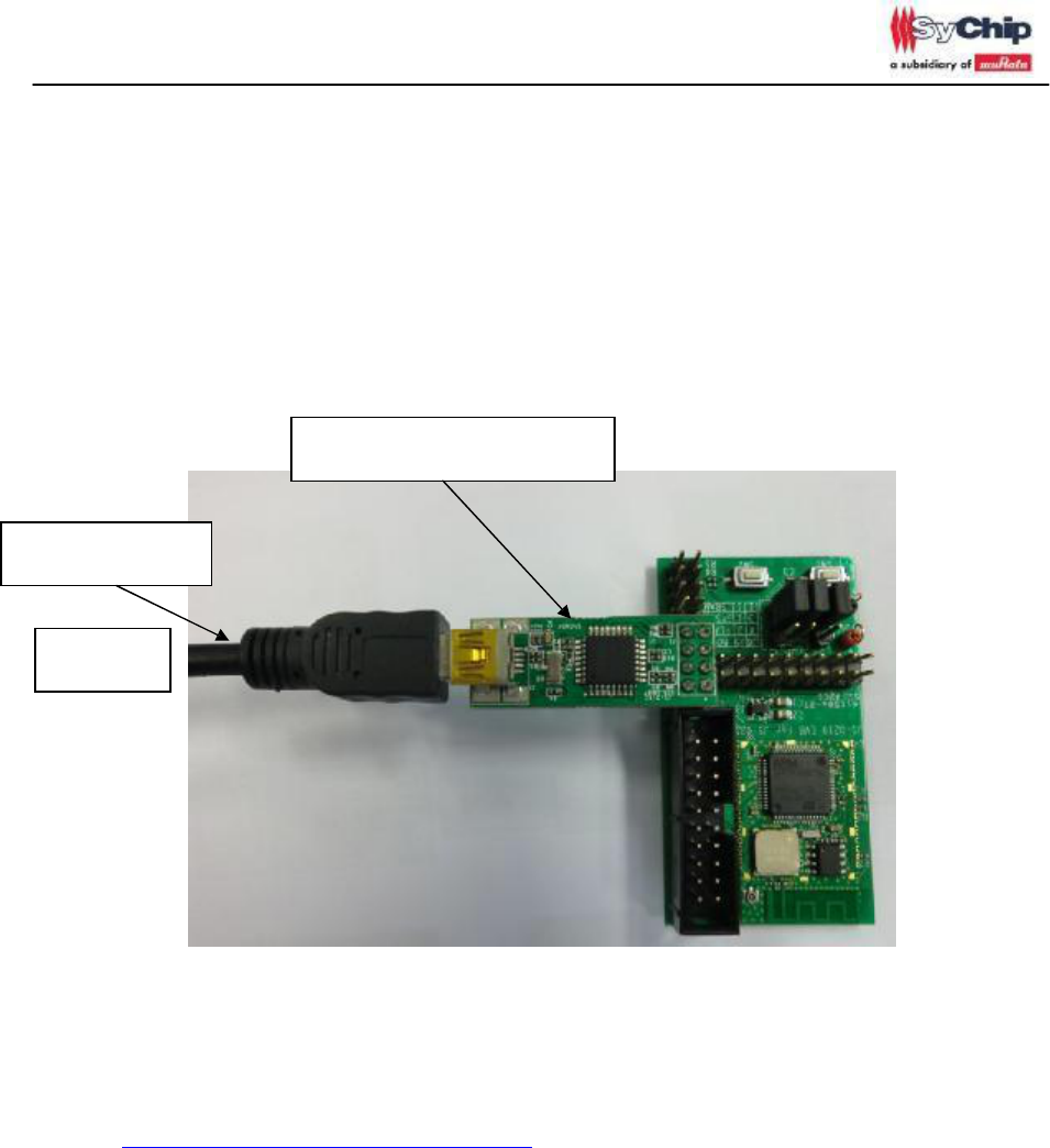
1. Connect EVK and PC through USB cable.
UART-USB converter boart
USB cable to PC
PC
Figure 2. Wireless-Uart EVK Demo
Under Wireless-Uart EVK normal mode, uart1 connected as shown in figure 2. Power supply through
uart1.
2. Install USB-UART converter driver (FTDI D2xx driver). Customer can download from below
website.
http://www.ftdichip.com/Drivers/D2XX.htm
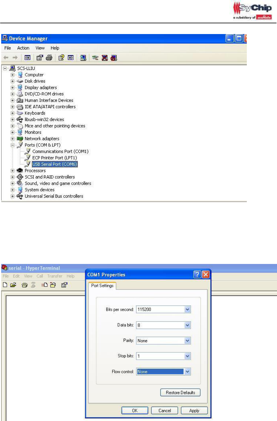
3. Please open device manager. Customer can see USB Serial Port if driver install is succeeded.
Sychip Wireless-Uart User Guide
www.sychip.com.cn
Page 6 of 12
Figure 3. usb serial port
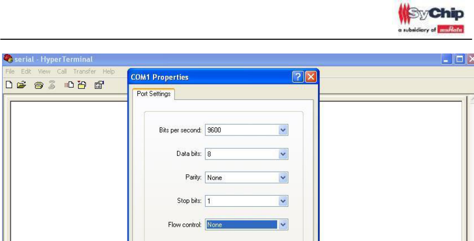
4. Then open serial terminal on the pc side, set the relevant parameters as shown in the following
figure. Baudrate = 115200, Data_bits = 8, Stop Bits = 1, pariyt = none, Flow Control = none. These
values are factory setting.
Note: Under the configuration mode, the uart parameters are same to the factory setting[1].
Figure 4. uart configuration
Sychip Wireless-Uart User Guide
www.sychip.com.cn
Page 7 of 12
2.2 Work Mode
2.2.1 TCP Server mode
Once EVK power on, the module start at factory setting mode[1].
1. Configuration the device’s TCP/IP properties.
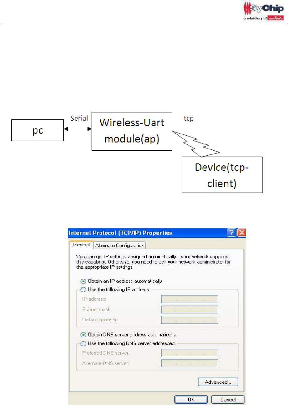
Obtain an ip address automatically, show as figure 5.
Figure 5. configuration the tcp/ip properties
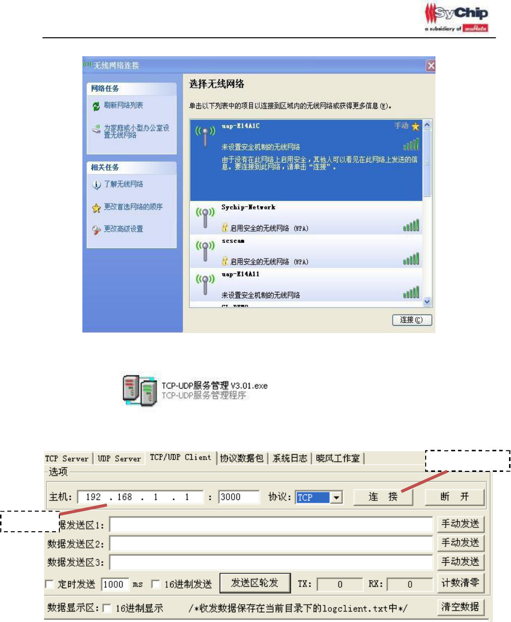
2. Scan and join the module ap on the device.
Show as figure 6.
Sychip Wireless-Uart User Guide
www.sychip.com.cn
Page 8 of 12
Figure 6. scan and join the module ap
3. Open tcp client on device side.
Set the server ip_addr=192.168.1.1, port=3000. Protocal=TCP. As show in the following figure:
Connect button
Server ip
Figure 7. tcp client configuration
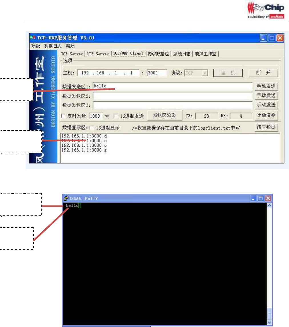
4. Click the connect button, achieved the transparent transmission.
Sychip Wireless-Uart User Guide
www.sychip.com.cn
Page 9 of 12
TCP Send
data
TCP Receive
data
Figure 8. tcp client transmission data on device
Uart Receive
data
Uart Send
data
Figure 9. uart transmission data on PC
This is the end of factory setting work mode.
2.2.2 TCP Client mode
2.2.3 UDP Server/Client mode
Sychip Wireless-Uart User Guide
www.sychip.com.cn
Page 10 of 12
2.4 Webpage Demo
2.1 SystemInfo
2.3 AT configuration commands
If customers press the configuration button when reset the device, the module into the configuration
mode. AT commands can use the uppercase or lowercase letters, but the parameters must be set
as special value, case-sensitive.
AT commands application:
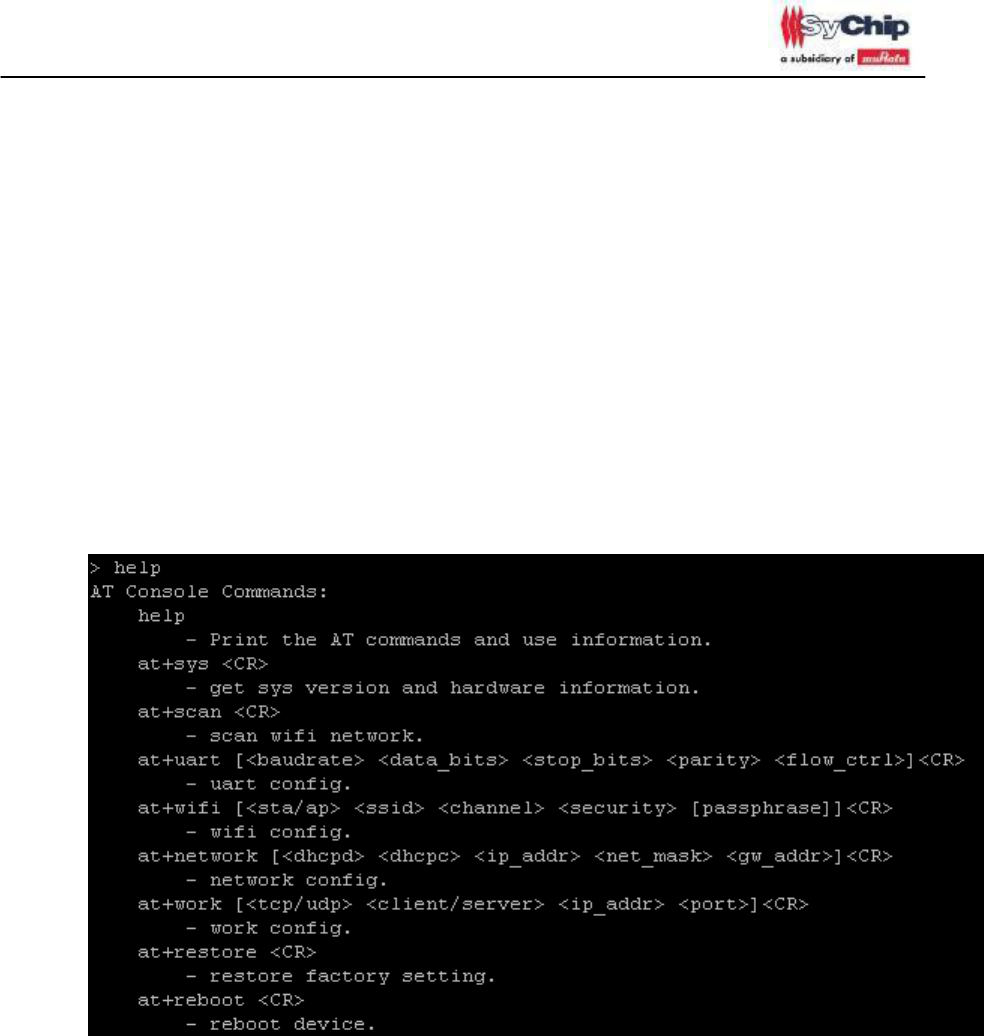
•
help /?:
Input “help” or ”?” <CR>. This command can show all the commands and use information.
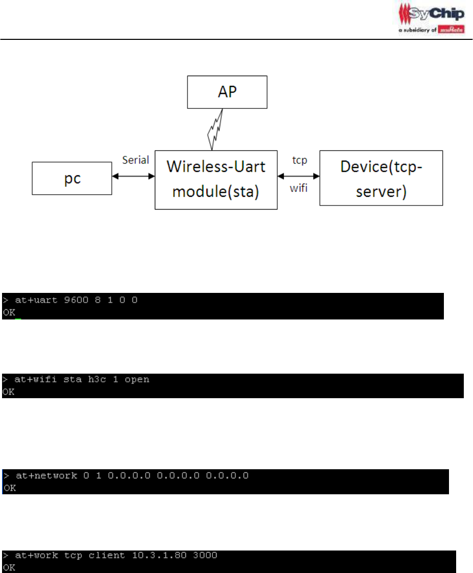
•
Tcp-client transmission configure.
Tcp-client work mode’s topology structure:
Sychip Wireless-Uart User Guide
www.sychip.com.cn
Page 11 of 12
(1) Uart parameters configuration
If need to change the uart parameters:
Example: BaudRate=9600, DataBits=8, StopBits=1, Parity=none, FlowCtrl=none.
(2) Wifi parameters configuration
If need to change the wifi mode as client:
Example connect h3c ssid: sta/ap=sta, ssid=h3c, channel=1, security=open
(3) Network parameters configuration
If need to change the network parameters:
Example enable the dhcpc, not use the static ip: dhcpd=0, dhcpc=1, ip_addr=0.0.0.0, net_mask=0.0.0.0,
gw_addr=0.0.0.0.
(4) Work module configuration
If need to change the work parameters:
Example change the work_mode as client: tcp/udp=tcp, client/server=client, ip_addr=10.3.1.80, port=3000.
After the configuration, Open serial terminal on the pc side.
Sychip Wireless-Uart User Guide
www.sychip.com.cn
Page 12 of 12
Then press the reset button, or input at+reboot command, the module into the tcp-client transmission
work mode.
All AT commands parameters’s value and function please reference document[1].
3. Reference documents
•
[1] Sychip wireless-uart interface.doc.
Statement
This equipment has been tested and found to comply with the limits for a Class B digital
device, pursuant to Part 15 of the FCC Rules. These limits are designed to provide
reasonable protection against harmful interference in a residential installation. This
equipment generates, uses and can radiate radio frequency energy and, if not installed
and used in accordance with the instructions, may cause harmful interference to radio
communications. However, there is no guarantee that interference will not occur in a
particular installation. If this equipment does cause harmful interference to radio or
television reception, which can be determined by turning the equipment off and on, the
user is encouraged to try to correct the interference by one or more of the following
measures: Reorient or relocate the receiving antenna; Increase the separation between
the equipment and receiver; Connect the equipment into an outlet on a circuit different
from that to which the receiver is connected; Consult the dealer or an experienced
radio/TV technician for help.
In accordance with FCC Part 15C, this module is listed as a Limited Modular Transmitter
device.
Therefore, the final host product must be submitted to [Sychip ] for confirmation that the
installation of the module into the host is in compliance with the regulations of FCC and
IC Canada. Specifically, if an antenna other than the model documented in the Filing is

Sychip Wireless-Uart User Guide
www.sychip.com.cn
Page 13 of 12
used, a Class 2 Permissive Change must be filed with the FCC.
Changes or modifications not expressly approved by the manufacturer could void the
user’s authority to operate the equipment.
FCC Label Instructions
The outside of final products that contains this module device must display a label
referring to the enclosed module. This exterior label can use wording such as the
following: “Contains Transmitter Module FCC ID: [VPYAAF]” or “Contains FCC ID:
[VPYAAF].” Any similar wording that expresses the same meaning may be used.
To satisfy FCC RF Exposure requirements for mobile and base station transmission
devices, a separation distance of 20 cm or more should be maintained between the
antenna of this device and persons during operation. To ensure compliance, operation at
closer than this distance is not recommended. The antenna(s) used for this transmitter
must not be co-located or operating in conjunction with any other antenna or transmitter.