Muratec Automation VEHICLEMCOM MCOM: Merge/divergecommunication Modem User Manual
Muratec Automation Co.,LTD MCOM: Merge/divergecommunication Modem Users Manual
UserManual.wiki
>
Muratec Automation
>
VEHICLEMCOM User Manual
Users Manual
Navigation menu
Upload a User Manual
Namespaces
Wiki Guide
HTML
PDF
Info
Views
User Manual
Discussion / Help
Navigation
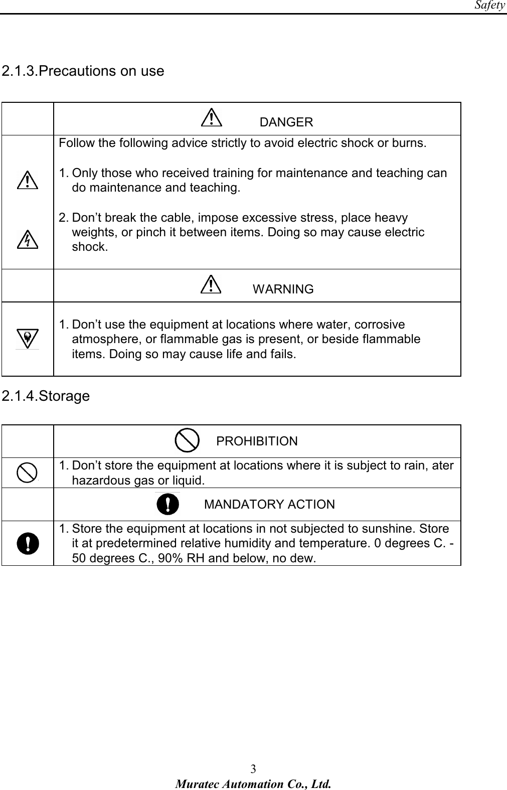
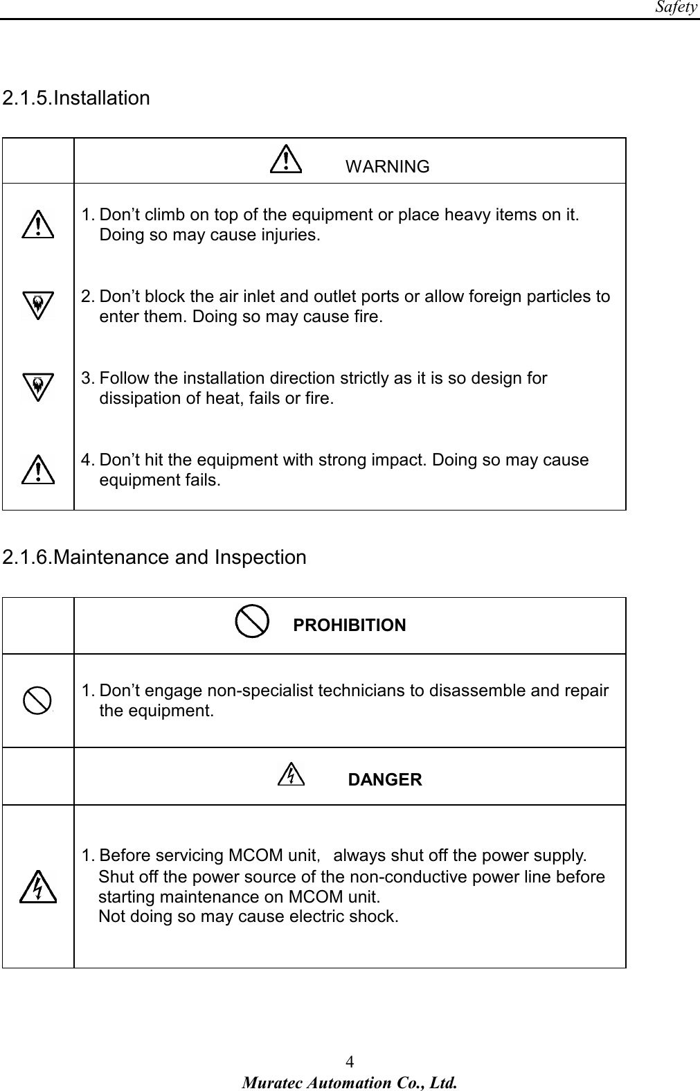
![Safety 2 Muratec Automation Co., Ltd. 2. Safety 2.1. Alert Boxes 2.1.1. General (1) Read and understand fully this manual and attached documents before operating the products. (2) Engage specialists in electrical and mechanical works. (3) Don’t improve the product by yourselves. (4) Be sufficiently proficient with the equipment, the relevant safety knowledge and the precautions prior to using this product. In the content of this “Safety Precautions ”, items which need to be alert shall be classified into “DANGER”, “WARNING” and ”CAUTION”. 2.1.2. Definitions of DANGER, WARNING and CAUTION DANGER: An imminently hazardous situation which, if not avoided, will result in death or serious injury. WARNING: A potentially hazardous situation which, if not avoided, could result in death or serious injury. CAUTION: A potentially hazardous situation which, if not avoided, may result in minor or moderate injury. [Note 1] Medium degree of injuries or light injuries refers to injuries, e.g., burns and electric shock, which do not require hospitalization of or prolonged hospital visit by the victims. As material losses refers to expanded losses pertaining to the damage of property and equipment. [Note 2] Depending on the situation, the events described under “WARNING” may also result in severe outcome. In either case, make sure that the advice is followed. After reading, make sure this information shall be kept at places where it can always be read by users.](https://usermanual.wiki/Muratec-Automation/VEHICLEMCOM/User-Guide-1432577-Page-6.png)

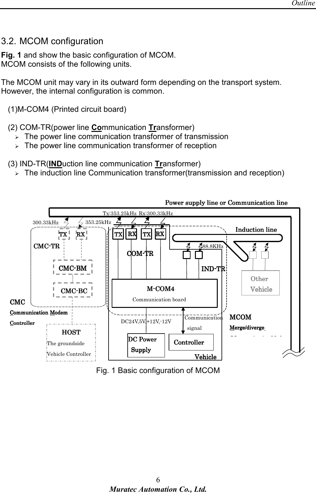

![Outline 11 Muratec Automation Co., Ltd. Fig. 5 The outer forms of the transformer IND-TR 3.4. FCC standard The transmission assembly in the communication unit MCOM meets FCC Part15 Subpart C as the intentional radiator. FCC ID of MCOM: ZBQVEHICLEMCOM [Note.1] The FCC certificate position may vary because different case materials and shapes are adopted for different customers. This device complies with part 15 of the FCC Rules.Operation is subject to the following two conditions;this device may not cause interference, and this device must accept any interference received, including interference that may cause undesired operation](https://usermanual.wiki/Muratec-Automation/VEHICLEMCOM/User-Guide-1432577-Page-15.png)
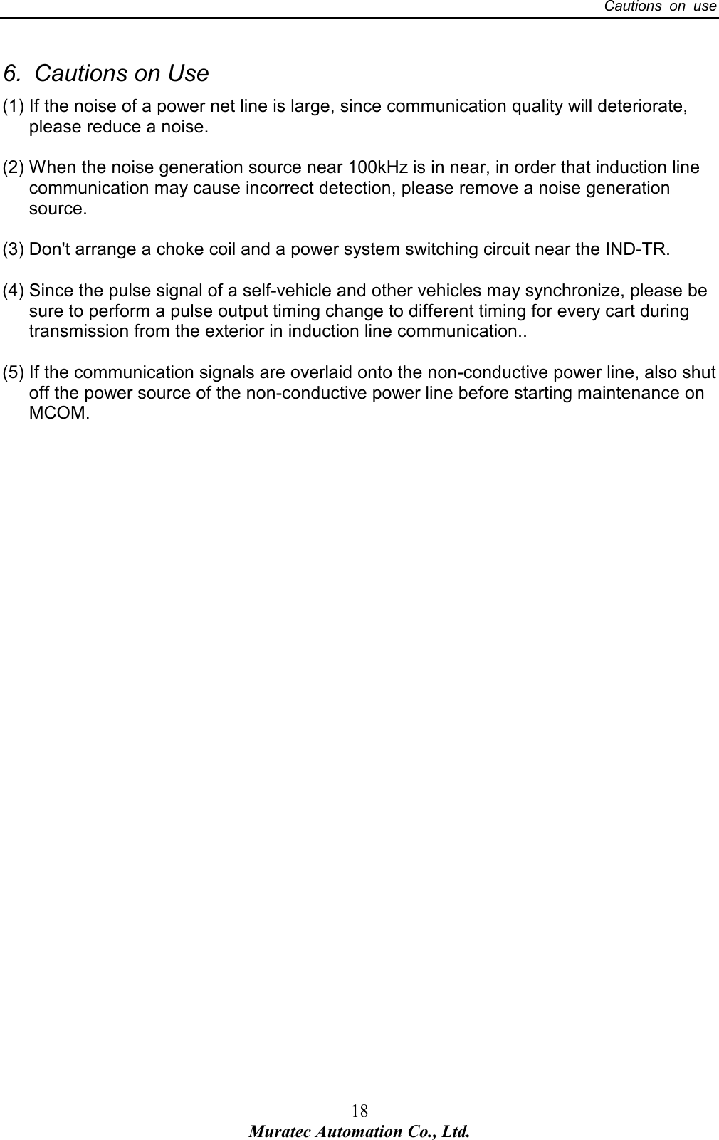
![Specification 17 Muratec Automation Co., Ltd. 5. Error process [Note.1] Before servicing MCOM,always shut off the power supply. [Note.2] If the communication signals are overlaid onto the non-conductive power line, also shut off the power source of the non-conductive power line before starting maintenance on MCOM. <Power net line Communication error trouble shooting> Communication error Is the Controller sending communication signals? Check the settings for the Controller. Are the power indicator lights of M-COM4 illuminated? Is the power supply of DC24V,5V and ±12V connected? Turn the power supply OFF. Is the input resistance of the DC power almost 0 ohm? Replace the DC power supply. Is the connection between the controller and M-COM4 normal? Restore connection. Is the connection between the COM-TR and M-COM4 normal? Restore connection. Is the noise of a power net line normal? The noise of a power net line is reduced. <Induction line Communication error trouble shooting> Communication error Is the Controller sending communication signals? Check the settings for the Controller. Are the power indicator lights of M-COM4 illuminated? Is the power supply of DC24V,5V and ±12V connected? Turn the power supply OFF. Is the input resistance of the DC power almost 0 ohm? Replace the DC power supply. Is the connection between the controller and M-COM4 normal? Restore connection. Is the connection between the IND-TR and M-COM4 normal? Restore connection. Isn't the source of a noise that emits 100kHz near IND-TR? Remove the source of a noise. Doesn't it disconnect a induction line? Restore disconnection of a guidance line.](https://usermanual.wiki/Muratec-Automation/VEHICLEMCOM/User-Guide-1432577-Page-21.png)