Muratec Automation VEHICLEMCOM MCOM: Merge/divergecommunication Modem User Manual
Muratec Automation Co.,LTD MCOM: Merge/divergecommunication Modem Users Manual
Users Manual

MCOM Operation Manual
Model: MCOM(M-COM4,COM-TR,IND-TR)
1
st
edition January 26, 2011
Control Design Section,
Semiconductor Engineering Dept.
MURATEC AUTOMATION CO., LTD.
Rev. Approved
Checked
Prepared
Rev.3 11.03.04
Change Filter rate switch
Rev.2 11.03.03
Change FCC ID
Rev.1 11.02.28
Change block diagram
Engineerring Dept
2011.2.10
Kawashima
Kawashima
Engineerring Dept
2011.2.10
Inagaki
Inagaki
Development Dept
2011.1.26
Onishi
Ohnishi
Doc. No.
YSDA-3490 Rev.3

ii
Muratec Automation Co., Ltd.
< Revision History >
Ver.
Date Page Description
0 2011/01/26 The first edition.
1 2011/02/28 10 Change block diagram
2 2011/03/03 5.11 Change FCCID
3 2011/03/04 8 Change Filter rate switch setting
iii
Muratec Automation Co., Ltd.
〈
〈〈
〈Contents〉
〉〉
〉
1. Introduction
................................
................................................................
................................................................
................................................................
...............................................
..............................
............... 1
11
1
1.1.
Application .......................................................................................................................1
1.2.
Related Rules, Laws........................................................................................................1
1.3.
Abbreviations...................................................................................................................1
2. Safety
................................
................................................................
................................................................
................................................................
.......................................................
..............................................
....................... 2
22
2
2.1.
Alert Boxes ......................................................................................................................2
2.1.1.
General......................................................................................................................................... 2
2.1.2.
Definitions of DANGER, WARNING and CAUTION .................................................................... 2
2.1.3.
Precautions on use....................................................................................................................... 3
2.1.4.
Storage ......................................................................................................................................... 3
2.1.5.
Installation .................................................................................................................................... 4
2.1.6.
Maintenance and Inspection......................................................................................................... 4
3. Outline of the Vehicle communication unit MCOM
.....................
..........................................
..................... 5
55
5
3.1.
Overview..........................................................................................................................5
3.2.
MCOM configuration........................................................................................................6
3.3.
Function of each unit .......................................................................................................7
3.3.1.
M-COM4 (Printed circuit board ) .................................................................................................. 7
3.3.2.
COM-TR (power line COMmunication TRansformer) .................................................................. 8
3.3.3.
IND-TR (INDuction line communication TRansformer)................................................................ 9
3.4.
FCC standard ................................................................................................................11
3.5.
Control/modulating of communication............................................................................12
3.5.1.
Power line communication ......................................................................................................... 12
3.5.2.
Induction line communication ..................................................................................................... 13
4. Specification
................................
................................................................
................................................................
................................................................
...........................................
......................
........... 14
1414
14
4.1.
Input/Output...................................................................................................................14
4.2.
Specification ..................................................................................................................15
4.2.1.
M-COM4 ..................................................................................................................................... 16
4.2.2.
COM-TR ..................................................................................................................................... 16
4.2.3.
IND-TR ....................................................................................................................................... 16
5. Error process
................................
................................................................
................................................................
................................................................
..........................................
....................
.......... 17
1717
17
6. Cautions on Use
................................
................................................................
................................................................
................................................................
.....................................
..........
..... 18
1818
18

Introduction
1
Muratec Automation Co., Ltd.
1. Introduction
1.1. Application
This document describes the operation of communication unit for transport system,
OHT, OHS, etc.
1.2. Related Rules, Laws
FCC part 15 subpart C
1.3. Abbreviations
(1) MCOM: Merge/diverge Communication Modem
(2) COM-TR: power line Communication Transformer
(3) IND-TR: INDuction line communication Transformer
(4) CMC : Communication Modem Controller
(5) CMC-BM: Communication Modem Controller :Base Modem
(6) CMC-BC: Communication Modem Controller :Base Controller
(7) CMC-TR: Communication Modem Controller :TRansformer

Safety
2
Muratec Automation Co., Ltd.
2. Safety
2.1. Alert Boxes
2.1.1. General
(1) Read and understand fully this manual and attached documents before operating the
products.
(2) Engage specialists in electrical and mechanical works.
(3) Don’t improve the product by yourselves.
(4) Be sufficiently proficient with the equipment, the relevant safety knowledge and the
precautions prior to using this product.
In the content of this “Safety Precautions ”, items which need to be alert shall be
classified into “DANGER”, “WARNING” and ”CAUTION”.
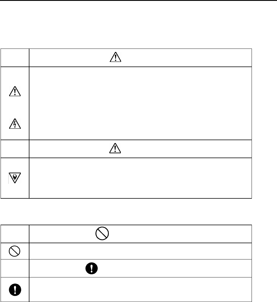
2.1.2. Definitions of DANGER, WARNING and CAUTION
DANGER: An imminently hazardous situation which, if not avoided, will result in
death or serious injury.
WARNING: A potentially hazardous situation which, if not avoided, could result
in death or serious injury.
CAUTION: A potentially hazardous situation which, if not avoided, may result in
minor or moderate injury.
[Note 1]
Medium degree of injuries or light injuries refers to injuries, e.g., burns and electric
shock, which do not require hospitalization of or prolonged hospital visit by the
victims. As material losses refers to expanded losses pertaining to the damage of
property and equipment.
[Note 2]
Depending on the situation, the events described under “WARNING” may also result
in severe outcome. In either case, make sure that the advice is followed.
After reading, make sure this information shall be kept at places where it can
always be read by users.
Safety
3
Muratec Automation Co., Ltd.
2.1.3. Precautions on use
DANGER
Follow the following advice strictly to avoid electric shock or burns.
1. Only those who received training for maintenance and teaching can
do maintenance and teaching.
2. Don’t break the cable, impose excessive stress, place heavy
weights, or pinch it between items. Doing so may cause electric
shock.
WARNING
1. Don’t use the equipment at locations where water, corrosive
atmosphere, or flammable gas is present, or beside flammable
items. Doing so may cause life and fails.
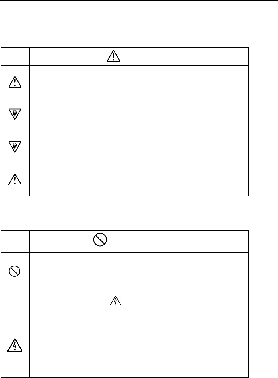
2.1.4. Storage
PROHIBITION
1. Don’t store the equipment at locations where it is subject to rain, ater
hazardous gas or liquid.
MANDATORY ACTION
1. Store the equipment at locations in not subjected to sunshine. Store
it at predetermined relative humidity and temperature. 0 degrees C. -
50 degrees C., 90% RH and below, no dew.
Safety
4
Muratec Automation Co., Ltd.
2.1.5. Installation
WARNING
1. Don’t climb on top of the equipment or place heavy items on it.
Doing so may cause injuries.
2. Don’t block the air inlet and outlet ports or allow foreign particles to
enter them. Doing so may cause fire.
3. Follow the installation direction strictly as it is so design for
dissipation of heat, fails or fire.
4. Don’t hit the equipment with strong impact. Doing so may cause
equipment fails.
2.1.6. Maintenance and Inspection
PROHIBITION
1. Don’t engage non-specialist technicians to disassemble and repair
the equipment.
DANGER
1. Before servicing MCOM unit,always shut off the power supply.
Shut off the power source of the non-conductive power line before
starting maintenance on MCOM unit.
Not doing so may cause electric shock.

Outline
5
Muratec Automation Co., Ltd.
3. Outline of the Vehicle communication unit MCOM
3.1. Overview
The communication unit MCOM (Merge/diverge Communication Modem) meet the
requirements of FCC Part15 Subpart C. The FCC ID is as follows.
FCC ID of MCOM: ZBQVEHICLEMCOM
1) Power line communication
MCOM is used for the communication between vehicle and the ground vehicle controller
in the transport system.
The communication signals are overlaid onto the power line for non-contact power
supply to the vehicles. In some systems, a separate signal lines may be used.
The communication unit CMC (Communication Modem Controller) is the groundside
communication unit. CMC is used for the communication between the groundside
vehicle controller and several vehicles.
CMC meet the requirements of FCC Part15 Subpart C. The FCC ID is as follows.
FCC ID of CMC: ZBQVEHICLECMC
MCOM modulate the signals sent from the vehicle and receive the modulated signals
from the ground vehicle controller. MCOM also demodulate the signals sent from the
groundside vehicle controller and transmit them to the ground vehicle controller.
The communication method in use is 2 levels FSK (frequency shift keying).
The communication frequencies are as follows.
From to Frequency
(1) CMC → MCOM: 300.33 kHz
(2) MCOM→ CMC: 353.25 kHz
2) Induction line communication
MCOM is used for the communication between vehicle and other Vehicle in the
transport system.
MCOM outputs the detection signal of one bit in the controller when the existence of the
signal which other vehicle transmitted.
An Induction line is installed on both sides of the track. Therefore one transformer and
circuit are each right and left, and they are equal. It can be changed if one transformer
is used for the reception or it is used for the transmission. A left-right IND-TR is
combined with the loop line, and it can watch each other's transmitting signal. Then, a
trouble such as the breakage of the transformer can be diagnosed.
The communication method in use is Adoption of On Off Keying Method.
The communication frequencies are 88.8kHz.
Outline
6
Muratec Automation Co., Ltd.
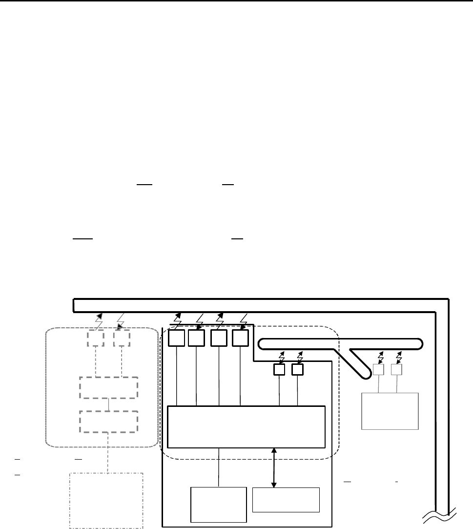
3.2. MCOM configuration
Fig. 1 and show the basic configuration of MCOM.
MCOM consists of the following units.
The MCOM unit may vary in its outward form depending on the transport system.
However, the internal configuration is common.
(1)M-COM4 (Printed circuit board)
(2) COM-TR(power line Communication Transformer)
The power line communication transformer of transmission
The power line communication transformer of reception
(3) IND-TR(INDuction line communication Transformer)
The induction line Communication transformer(transmission and reception)
M
MM
M-
--
-COM
COMCOM
COM4
44
4
Communication board
CMC
CMCCMC
CMC
-
--
-
BC
BCBC
BC
CMC
CMCCMC
CMC
-
--
-
BM
BMBM
BM
CMC
CMCCMC
CMC
C
CC
C
ommunication
ommunication ommunication
ommunication M
MM
M
odem
odem odem
odem
C
CC
C
ontroller
ontrollerontroller
ontroller
Other
OtherOther
Other
Vehicle
Vehicle Vehicle
Vehicle
HOST
HOSTHOST
HOST
The groundside
Vehicle Controller
Vehicle
VehicleVehicle
Vehicle
COM
COMCOM
COM
-
--
-
TR
TRTR
TR
IND
INDIND
IND-
--
-TR
TRTR
TR
88.8KHz
Tx:353.25kHz
Rx:300.33kHz
353.25kHz
300.33kHz
Induction
InductionInduction
Induction line
line line
line
Power supply
Power supplyPower supply
Power supply line
line line
line or Comm
or Comm or Comm
or Communication line
unication lineunication line
unication line
CMC
CMCCMC
CMC-
--
-TR
TRTR
TR
M
MM
MC
CC
COM
OMOM
OM
M
MM
Merge/diverge
erge/divergeerge/diverge
erge/diverge
CO
COCO
CO
mmunication
mmunication mmunication
mmunication
M
MM
M
odem
odemodem
odem
RX
RXRX
RX
TX
TXTX
TX
RX
RXRX
RX
TX
TXTX
TX
DC Power
DC PowerDC Power
DC Power
Supply
Supply Supply
Supply
DC24V,5V,+12V,-12V
Controller
ControllerController
Controller
Communication
signal
TX
TXTX
TX
RX
RXRX
RX
Fig. 1 Basic configuration of MCOM

Outline
7
Muratec Automation Co., Ltd.
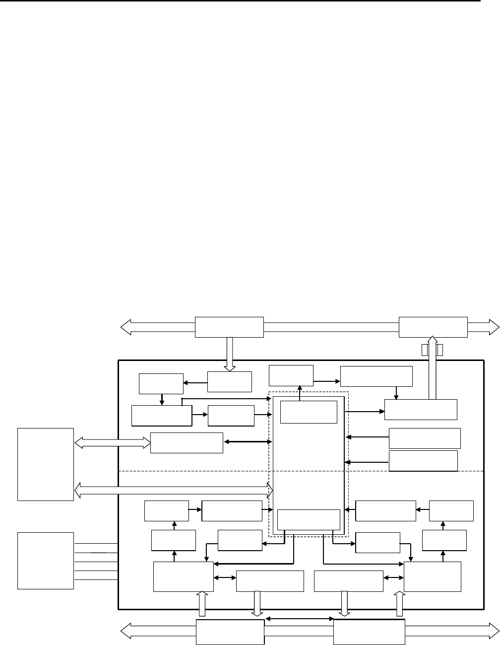
3.3. Function of each unit
Fig. 2 shows the block diagram of M-COM4.
In addition, the MCOM unit may vary in its outward form depending on the transport
system. However, the internal configuration is common.
All units are connected by the cable.
3.3.1. M-COM4
(Printed circuit board )
M-COM4 is a print board with two communication functions, power line communication
and induction line communication.
Fig. 3 shows the outward form of the printed circuit board M-COM4.
1) Power line communication
M-COM4 board is an interface unit to handle the signals from/to the groundside vehicle
controller.
A signal is transmitted and received by the order of the controller.
This is a modem unit to handle the signals from/to the groundside vehicle controller.
It incorporates a driver that modulates the digital signals sent from the controller to
analog signals and overlay the converted signals onto the non-contact power supply line
or signal line.
It also demodulates the analog signals sent from the groundside vehicle controller to
digital signals and transmit them to controller.
2) Induction line communication
M-COM4 board is an interface unit to handle the signals from/to the other vehicles.
A signal is transmitted and received by the order of the controller.
This is a modem unit to handle the signals from/to the other vehicles.
It incorporates a driver that modulates the digital signals sent from the controller to
analog signals and overlay the converted signals onto the induction line.
It also demodulates the analog signals sent from the other vehicles to digital signals and
transmit them to controller.
The receiving circuit and the transmitting circuit are prepared by the set to the induction
coil on either side. It can change whether a receiving circuit is connected or a
transmitting circuit is connected with the setting signal from the controller to a
right-and-left IND-TR.
Intermittent sending of the 88.88kHz digital signal is carried out from the signal
generating circuit, and a transmitted signal is amplified with transmitting amplifier, and is
transmitted with a coil.
The capacitor for resonance is connected to a coil in series, and voltage amplification of
the 88.88kHz is carried out alternatively.
A receiving circuit converts into a pulse signal the modulation signal received with the
receiving coil, and counts the number of pulses by the signal detector.
If it becomes beyond a value with the number of counts, it will be considered that other
vehicles were detected.
Outline
8
Muratec Automation Co., Ltd.
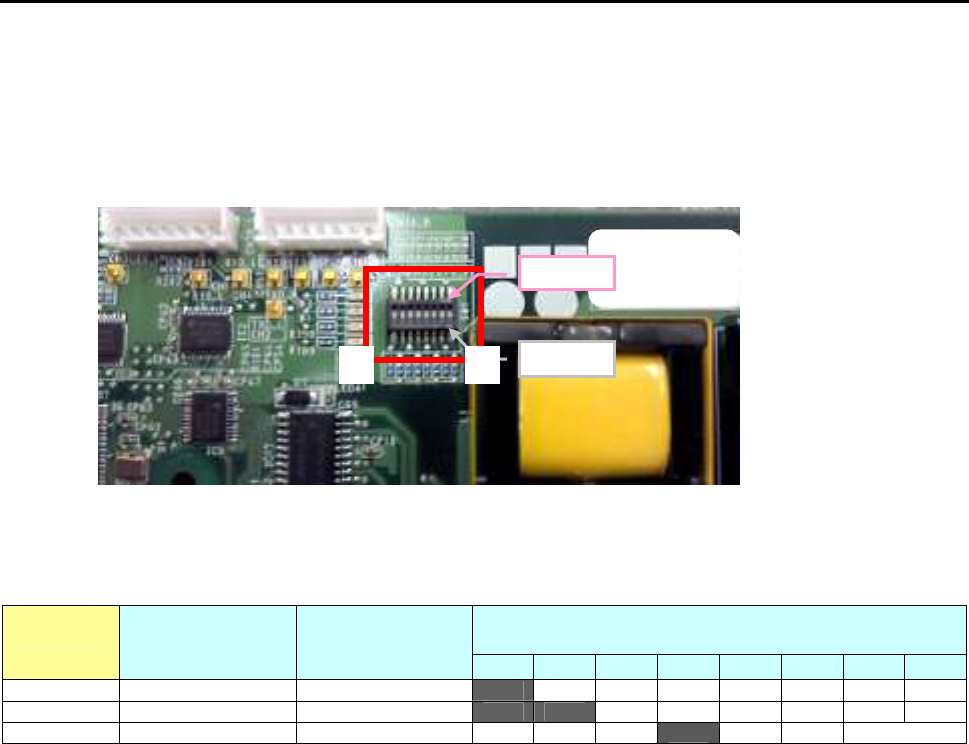
In M-COM4, the following variation is, and the setting of the dip switch is different
because of the vehicle model. The setting is changed with switch 1-6.
The setting of switch 1-6 do not change, please.
Switch 7-8 is a switch that sets the baud rate of the filter for the noise cancellation built
into M-COM4. It is effective in M-COM4A-G3-2.
Fig 2.
..
.Switch for selecting a vehicle model
Table 1 Application table
DSW1 Applicable
Vehicle
Part Number Part Name
1 2 3 4 5 6 7 8
G1 series HM2-G2730-500 M-COM4A-G1
on off off off off off
- -
G2 series HM2-G2737-500 M-COM4A-G2
on on off off off off
- -
G3-2 HM2-G2732-500 M-COM4A-G3
off off off on off off
*1
*1: Filter rate switch
(7,8)=
(on,off)= 19.2kbps
(off,on)= 28.8kbps
3.3.2. COM-TR
(power line COMmunication TRansformer)
The transmission transformer overlays the signals from the controller onto the
non-conductive power line or signal line.
The reception transformer receives the signals from vehicles overlaid in the non-conduct
power line or signal line.
OFF
1
8
ON
Outline
9
Muratec Automation Co., Ltd.
Fig. 4 shows the outer forms of the transformers.
*The COM-TR may vary in its outward form depending on the transport system. However,
the internal configuration is common.
3.3.3. IND-TR
(INDuction line communication TRansformer)
The transmission transformer overlays the signals from the controller onto the induction
line.
The reception transformer receives the signals from vehicles overlaid in the induction line.
It can be changed if one transformer is used for the reception or it is used for the
transmission.
A left-right IND-TR is combined with the loop line, and it can watch each other's
transmitting signal. Then, a trouble such as the breakage of the transformer can be
diagnosed.
Fig. 5 shows the outer forms of the transformers.
*The IND-TR may vary in its outward form depending on the transport system. However,
the internal configuration is common.
IN
ININ
IN
IN
ININ
IN
CO
COCO
CO
CO
COCO
CO
PCB:
Or
Communication line
CPU
Board
Reset Circuit
Demodulator
Control logic
Modulator
Squelch
RX
-
Amp.
TX
-
Amp.
Resonance circuit
Serial I/F(TTL)
RX
-Filter
RX
-
transformer
TX
-
transfor
mer
Ferrite core
Power Line
353.25kHz
300.33kHz
Switch circuit
Switch cir
cuit
TX
-
Amp.
Resonance circuit Resonance circuit
RX
-
Amp.
RX
-
Filter.
Demodulator
X
’
tal OSC(24MHz)
TX
-
Amp. RX
-Filter.
Demodulator
RX
-
Amp.
Modulator
Left
-
transformer
Right
-
transformer
Induc
tion Line
88.8kHz
88.8kHz
Power Line Communication Part
Power Line Communication PartPower Line Communication Part
Power Line Communication Part
Induction Line Communication Part
Induction Line Communication PartInduction Line Communication Part
Induction Line Communication Part
M
MM
M
-
--
-
COM
COMCOM
COM
4
44
4
Power
Supply
Parallel
DIO
+24V
+5V
+12V
0V
-
12V
M
MM
M
COM
COM COM
COM
Block Diagram
Block DiagramBlock Diagram
Block Diagram
Switch circuit
Fig. 2
The block diagram of MCOM
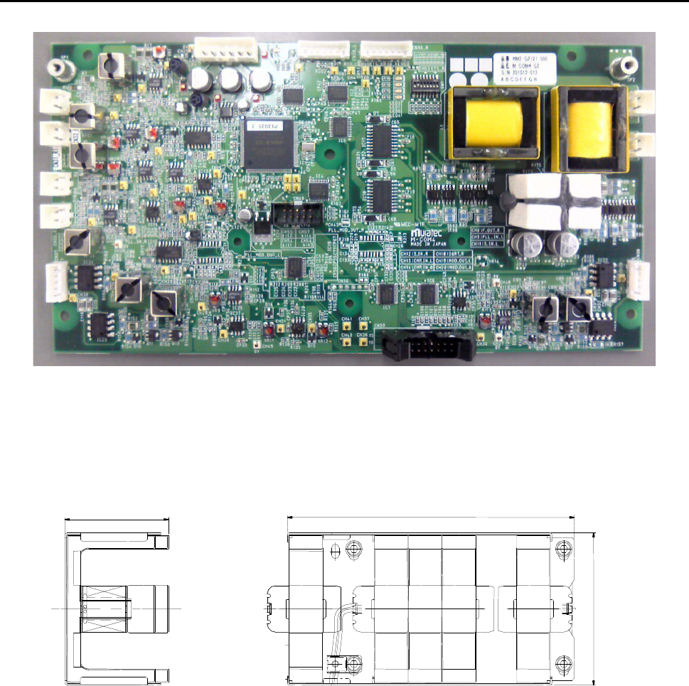
Outline
10
Muratec Automation Co., Ltd.
Fig. 3 Outward form of the MCOM's main printed circuit board M-COM4
Fig. 4 For example the outline form of the transformer COM-TR
169
61
90
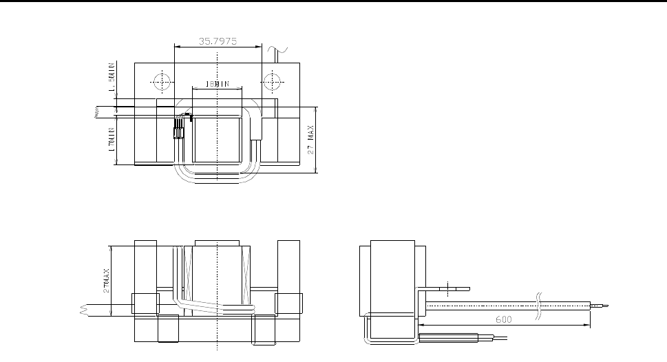
Outline
11
Muratec Automation Co., Ltd.
Fig. 5 The outer forms of the transformer IND-TR
3.4. FCC standard
The transmission assembly in the communication unit MCOM meets FCC Part15 Subpart
C as the intentional radiator.
FCC ID of MCOM: ZBQVEHICLEMCOM
[Note.1]
The FCC certificate position may vary because different case materials and shapes are
adopted for different customers.
This device complies with part 15 of the FCC Rules.Operation is subject to the following
two conditions;this device may not cause interference, and this device must accept any
interference received, including interference that may cause undesired operation
Outline
12
Muratec Automation Co., Ltd.
NOTICE
This equipment has been tested and found to comply with the limits for a Class A digital device,
pursuant to part 15 of the FCC Rules. These limits are designed to provide reasonable protection
against harmful interference when the equipment i
s operated in a commercial environment. This
equipment generates, uses, and can radiate radio frequency energy and, if not installed and used in
accordance with the instruction manual, may cause harmful interference to radio communications.
Operation of
this equipment in a residential area is likely to cause harmful interference in which
case the user will be required to correct the interference at his own expense.
FCC WARNING
Changes or modifications not expressly approved by the party responsible for
compliance could
void the user's authority to operate the equipment.
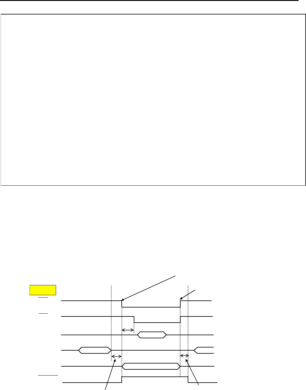
3.5. Control/modulating of communication
3.5.1. Power line communication
Control/modulating of communication use the connector CN30.
A communication-timing chart is shown in the Fig. 6.
Please control signal according to the communication chart shown in Fig. 6.
In addition, all the signals are TTL-Level.
RTS
CTS
TXD
RXD
Carrier
200usec
Min. 833usec
533usec
M
MM
M-
--
-COM4
COM4COM4
COM4
DATA
DATA
Please prepare the waiting time for 833 seconds
or more with the software by the side of ATI.
When you finish transmitting
data, please disable a signal of
RTS for reception of the following
data.
Since the mask of reception on an
M-COM4
board is covered for 200usec after
RTS becomes disable.
When you transmit a signal, enable an RTS signal.
RX Ready
(MASK)
Note.
Signal of “Carrier” and “RX Ready(MASK)” are internal signals of the M-COM2 board.
From the groundside
vhicle controller
Fig. 6 Power net line communication-timing chart of MCOM
Outline
13
Muratec Automation Co., Ltd.
1) The 533usec delay circuit is the circuit to guarantee, from the time that a
request-to-send signal (RTS) outputted from the controller is generated, to the time
that a transmitting circuit attains to the rated value. Time is up in 533usec after RTS
was set to ON, and a clear-to-send signal (CTS) returns to controller.
2) The 200-μsec Delay circuit masks transmitted signal during the time from the end of
the request-to-send (RTS) till the lapse of transmitted signal against received signal,
as the enabled transmitted signal may affect receiving circuit, Resulting in erratic
output. This delay circuit times out in 200μsec after the RTS is ended.
3) After receiving data from the groundside vehicle controller, please prepare the
waiting time for 833 seconds or more with the software by the side of ATI. When
fewer than this time, it is because a NBV-BC substrate cannot receive data.
3.5.2. Induction line communication
Control/modulating of communication use the connector CN39.
A communication-Logic table is shown in the Table. 2.
Please control signal according to the communication table shown in Table. 2.
In addition, all the signals are TTL-Level.
For example, when you want to transmit from a left IND-TR and to receive from a right
IND-TR, please make a signal into
Table. 1
Table. 1
Signal status (
transmit: left IND-TR, receive: right IND-TR)
CN39
pin
Signal
name Direction signal
1 L Input L
2 R Input H
3 LON Input L
4 RON Input X
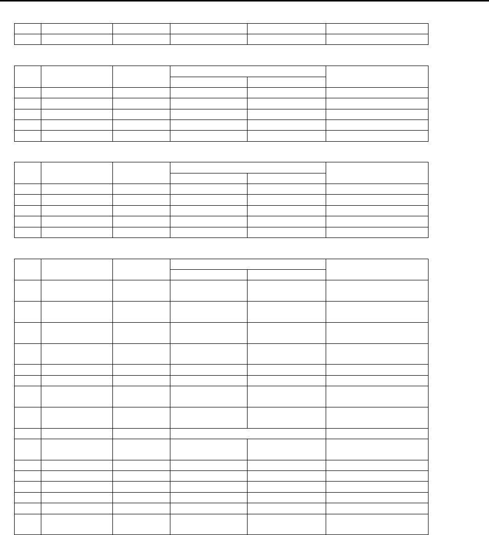
When M-COM4 breaks down, the breakdown signal is output. Breakdown signals are 10
pins of CN39.
The detection of the breakdown by feeds back the transmission signal of 88.8kHz to the
reception circuit, checks, and when the signal cannot be received though it transmits, is
breakdown output.
The main content to break down is disconnected IND-TR, and is a breakdown of M-COM4
internal circuit, etc.
The pulse signal that always repeats ON/OFF of each 30msec from 9 pins of CN39 is
output. The controller can confirm whether the M-COM4 circuit operates by observing this
signal.
Specification
14
Muratec Automation Co., Ltd.
4. Specification
4.1. Input/Output
Input and output ,and pin assigns of M-COM4 board are shown in Table. 2.
Table. 2
Input and output ,and pin assigns of M-COM4 board
CN35 DC Power Supply
Operation
pin signal Direction
L H
I/F
1 +24V in - - power
2 +5V in - - power
3 DG - - - GND(+24V,+5V)
4 +12V in - - power
5 AG - - - GND(+12V,-12V)
6 -12V in - - power
CN30L Power Line Communication control/modulation signal Left
Operation
pin signal Direction
L H
I/F
1 DG - - - GND(+24V,+5V)
2 CTS_L out Clear to send TTL
3 RXD_L out 0 1 TTL
4 DG -
5 RTS_L in Request to send
TTL
6 TXD_L in 0 1 TTL
7 DG -
8 R_SET in Select Right TTL
9 L_SET in Select Left TTL
CN30R Power Line Communication control/modulation signal Right
Operation
pin signal Direction
L H
I/F
1 DG - - - GND(+24V,+5V)
2 CTS_L out Clear to send TTL
3 RXD_L out 0 1 TTL
4 DG -
5 RTS_L in Request to send
TTL
6 TXD_L in 0 1 TTL
7 DG -
CN31L COM_TR(Left Receiver)
Operation
pin signal Direction
L H
I/F
1 Signal+ in analog
2 Signal- in analog
CN32R COM_TR(Right Receiver)
Operation
pin signal Direction
L H
I/F
1 Signal+ in analog
2 Signal- in analog
CN33 COM_TR(Left Transmitter)
Operation
pin signal Direction
L H
I/F
1 Signal+ out analog
2 Signal- out analog
CN34 COM_TR(Right Transmitter)
Operation
pin signal Direction
L H
I/F
Specification
15
Muratec Automation Co., Ltd.
1 Signal+ out analog
2 Signal- out analog
CN37 IND_TR(Left Transceiver)
Operation
pin signal Direction
L H
I/F
1 Signal+ in/out analog
2 (NC)
3 GND - For Shield
4 (NC)
5 Signal- in/out analog
CN38 IND_TR(Right Transceiver)
Operation
pin signal Direction
L H
I/F
1 Signal+ in/out analog
2 (NC)
3 GND - For Shield
4 (NC)
5 Signal- in/out analog
CN39 Induction Line control signal
Operation
pin signal Direction
L H
I/F
1 L-SET in Transmitter
mode
Receiver mode TTL
2 R-SET in Transmitter
mode
Receiver mode TTL
3 L-ON in Left
transmission on
off TTL
4 R-ON in Right
transmission on
off TTL
5 DG -
6 DG -
7 L-LED out off Left detect LED
on
TTL
8 R-LED out off Right detect
LED on
TTL
9 WDP out Watch dog pulse TTL
10 ERROR out normal Induction coil
broken
TTL
11 L-DETECT out off Left detect TTL
12 R-DETECT out off Right detect TTL
13 DG -
14 DG -
15 (DUTL) out off Left front detect TTL
16 (DUTR) out off Right front
detect
TTL
4.2. Specification
Power line communication speed: 19.2 kbps (MAX 38.4 kbps)
Power line communication method: 2 levels FSK
Induction line communication method: On/Off keying
Specification
16
Muratec Automation Co., Ltd.
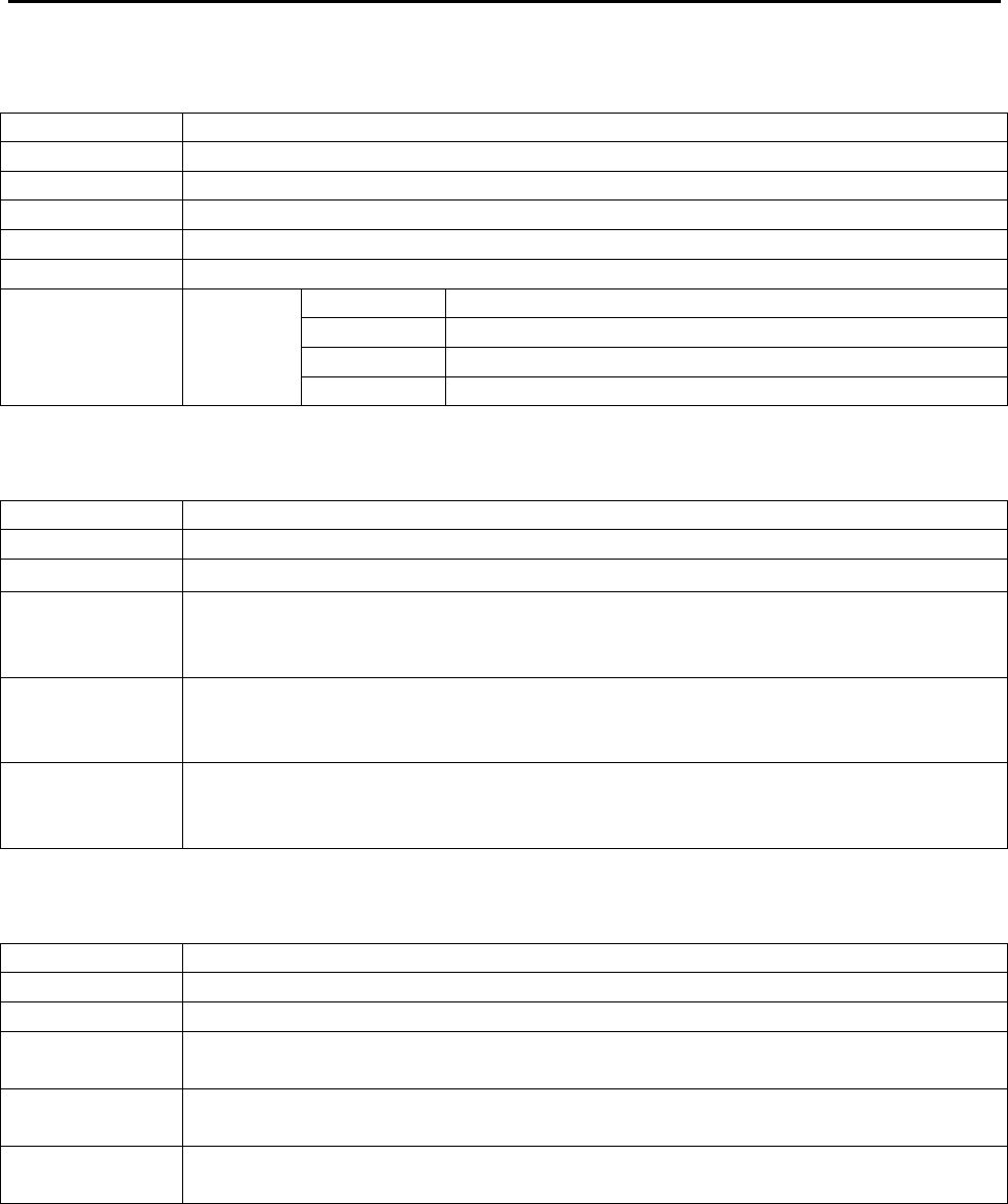
4.2.1. M-COM4
Name Printed circuit board:M-COM4
Manufacturer MURATEC AUTOMATION CO.,LTD
Model number
HM2-G2737-500, HM2-G2730-500, HM2-G2732-500
Weight Approx. 0.5 kgf
Size 125 (W) x 240mm (L) x 30mm (H)
Input Voltage
DC power supply 24V, 5V, 12V, -12V
DC24V 22.5W
DC5V 2W
DC12V 1.5W
Power
consumption 27W
DC-12V 1W
4.2.2. COM-TR
Unit name COM-TR
Manufacturer MURATEC AUTOMATION CO.,LTD
Model number
Z90679200□
Weight
Approx.1.6kgf
*Case materials, shape and power supply transformer vary with the
system.
Size
90mm (W) x 169 mm (L) x 61 mm (H)
*Case materials, shape and power supply transformer vary with the
system.
Power
consumption
MAX 1W
*When communication signal transmitted through the non-contact power
line.
4.2.3. IND-TR
Unit name IND-TR
Manufacturer MURATEC AUTOMATION CO.,LTD
Model number
Z906846200, Z906846300
Weight Approx.0.3kgf
*Case materials and shape vary with the system.
Size 67.5mm (W) x 50mm (L) x 43mm (H)
*Case materials and shape vary with the system.
Power
consumption
MAX 1W
*When communication signal transmitted through the induction line.
Specification
17
Muratec Automation Co., Ltd.
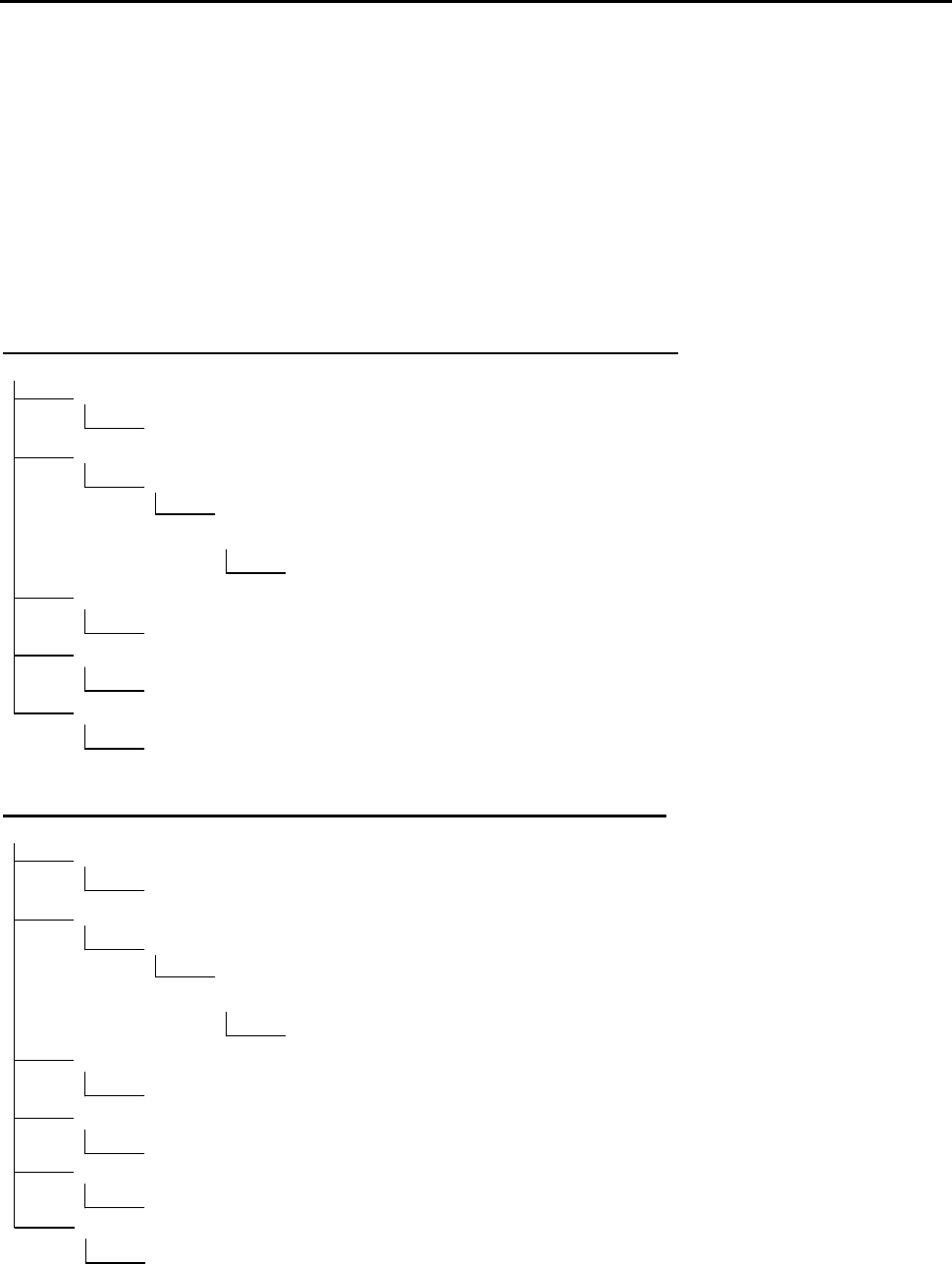
5. Error process
[Note.1]
Before servicing MCOM,always shut off the power supply.
[Note.2]
If the communication signals are overlaid onto the non-conductive power line, also shut off
the power source of the non-conductive power line before starting maintenance on
MCOM.
<Power net line Communication error trouble shooting>
Communication error
Is the Controller sending communication signals?
Check the settings for the Controller.
Are the power indicator lights of M-COM4 illuminated?
Is the power supply of DC24V,5V and ±12V connected?
Turn the power supply OFF. Is the input resistance of the DC power
almost 0 ohm?
Replace the DC power supply.
Is the connection between the controller and M-COM4 normal?
Restore connection.
Is the connection between the COM-TR and M-COM4 normal?
Restore connection.
Is the noise of a power net line normal?
The noise of a power net line is reduced.
<Induction line Communication error trouble shooting>
Communication error
Is the Controller sending communication signals?
Check the settings for the Controller.
Are the power indicator lights of M-COM4 illuminated?
Is the power supply of DC24V,5V and ±12V connected?
Turn the power supply OFF. Is the input resistance of the DC power
almost 0 ohm?
Replace the DC power supply.
Is the connection between the controller and M-COM4 normal?
Restore connection.
Is the connection between the IND-TR and M-COM4 normal?
Restore connection.
Isn't the source of a noise that emits 100kHz near IND-TR?
Remove the source of a noise.
Doesn't it disconnect a induction line?
Restore disconnection of a guidance line.

Cautions on use
18
Muratec Automation Co., Ltd.
6. Cautions on Use
(1) If the noise of a power net line is large, since communication quality will deteriorate,
please reduce a noise.
(2) When the noise generation source near 100kHz is in near, in order that induction line
communication may cause incorrect detection, please remove a noise generation
source.
(3) Don't arrange a choke coil and a power system switching circuit near the IND-TR.
(4) Since the pulse signal of a self-vehicle and other vehicles may synchronize, please be
sure to perform a pulse output timing change to different timing for every cart during
transmission from the exterior in induction line communication..
(5) If the communication signals are overlaid onto the non-conductive power line, also shut
off the power source of the non-conductive power line before starting maintenance on
MCOM.