MyBinding Duplo Dbm 120 Service Manual User
2013-06-04
User Manual: MyBinding Duplo-Dbm-120-Service-Manual
Open the PDF directly: View PDF ![]() .
.
Page Count: 44


STAPLER FOLDER
DBM-120
MAINTENANCE MANUAL

11C-M12M0-0004-0
TABLE OF CONTENTS
CHAPTER 1 MECHANISM
1. Outline of Each Mechanism and
Adjustments ....................................................1-2
2. Maintenance ...................................................1-11
CHAPTER 2 ELECTRICAL
COMPONENTS
1. Block Diagram of Structure and Outline of
Each Block ......................................................2-2
2. Errors and Causes ..........................................2-10
3. Maintenance Mode .........................................2-17
4. Precautions on Replacing the MC Unit ...........2-19
5. Precautions on Replacing Fuses .................... 2-20
6. LCD Map .........................................................2-21
7. Overall Schematic Diagram ............................ 2-27
8. Wiring Diagram ............................................... 2-28

1-1
11C-M12M0-0004-0
CHAPTER 1
MECHANISM
1. Outline of Each Mechanism and
Adjustments ....................................................1-2
1-1. Conveyance Mechanism (Entrance)......1-2
1-2. Back Jogger Mechanism ....................... 1-2
1-3. Side Jogger Mechanism ........................ 1-3
1-4. Stapler/Clincher Mechanism .................. 1-4
1-5. Folding Knife/Folding Roller
Mechanism ............................................1-8
1-6. Folding Conveyance Mechanism...........1-9
1-7. Stopper Mechanism ............................... 1-9
1-8. Conveyance Mechanism (Exit) ..............1-10
2. Maintenance ...................................................1-11
1-2
11C-M12M0-0004-0
1. OUTLINE OF EACH MECHANISM AND ADJUSTMENTS
Adjustments
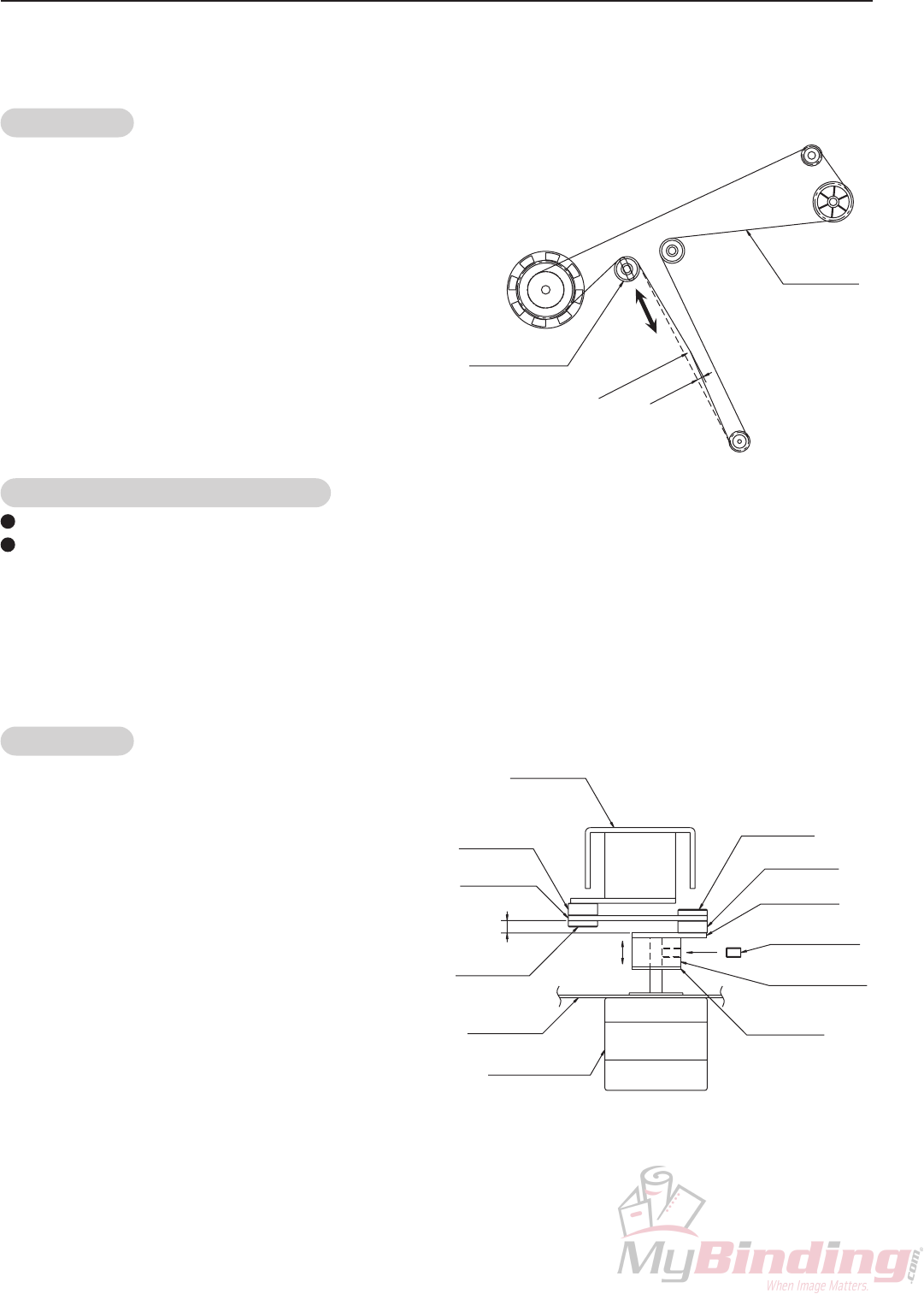
(1) Adjusting the tension of the timing belt
Adjust the position of the pinch roller unit so that the
belt slacks by 10 mm when a pressure of 1.96 N
(200 gf) is applied.
Timing belt
014-10243
Pinch roller unit
96F-1125X
1.96 N (200 gf)
10 mm
Precautions on replacing the flat belt
Replace taking note of the rotating direction of the flat belt. (Arrow at the back of the flat belt)
Replace the flat belt in pairs.
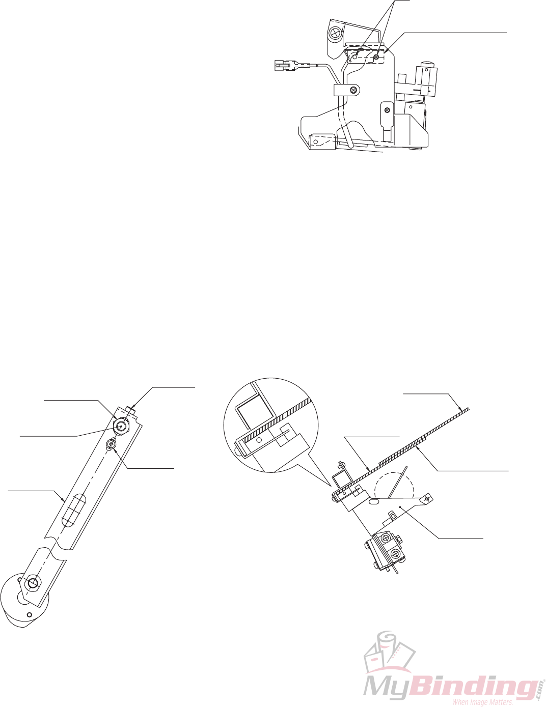
1-2. Back Jogger Mechanism
The base moves forward and backward by changing the rotating movements of the stepping motor to linear
movements.
The pusher attached to the base pushes in the paper.
Adjustments
(1) Adjusting the position of the collar 05-20-12
Adjust the position of the collar 05-20-12 so that the
lever and link become parallel.
1-1. Conveyance Mechanism (Entrance)
Paper is conveyed by the flat belt.
0Z4-08022
11C-1332X
11C-1310X
0Z4-08022
11C-1324X
Unbrako4 ×6
0X4-12050
Stepping motor
99A-8013X
Link
98H-1322X
Lever
Plate
11C-1334X
ZCollar 05-20-12
11C-1333X
Parallel
X
Bracket
X
0X4-12050
Z
Base plate
1-3
11C-M12M0-0004-0
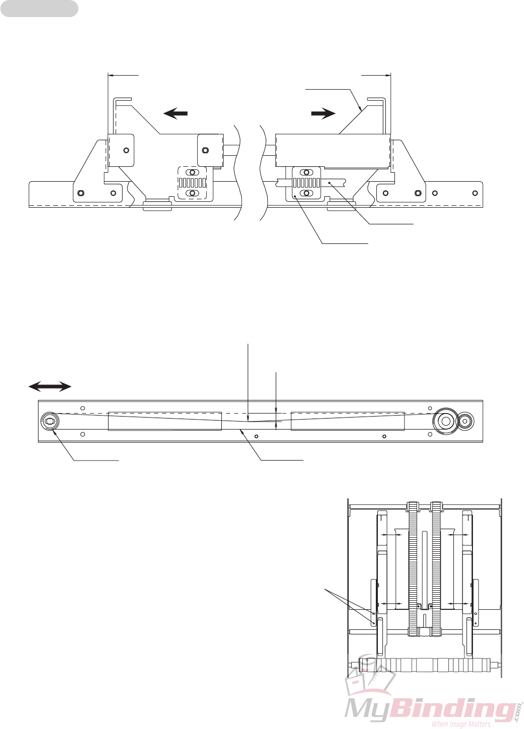
1-3. Side Jogger Mechanism
The timing belt moves forward and backward from the rotating movements of the stepping motor.
The jog plate pushes in the paper.
Adjustments
(1) Fixing the STS belt and bracket
With the bracket touches against the two sides, fix the plate and STS belt.
(2) Adjusting the tension of the STS belt
Adjust the position of the pulley unit so that the belt slacks by 10 mm when a pressure of 0.98 N (100 gf) is
applied.
(3) Adjusting the parallelity of the jog plate
Adjust the distance (difference between A and A'
and that between B and B') between the groove of
the guide plate and jog plate to below 0.5 mm.
Bracket
11C-1635X
Touch
Plate
11C-1637X STS belt
014-10386
Touch
A
A'
B
B'
Attaching screws
0.98 N (100 gf)
014-10386
11C-1656X
STS belt
Pulley unit
10 mm
1-4
11C-M12M0-0004-0
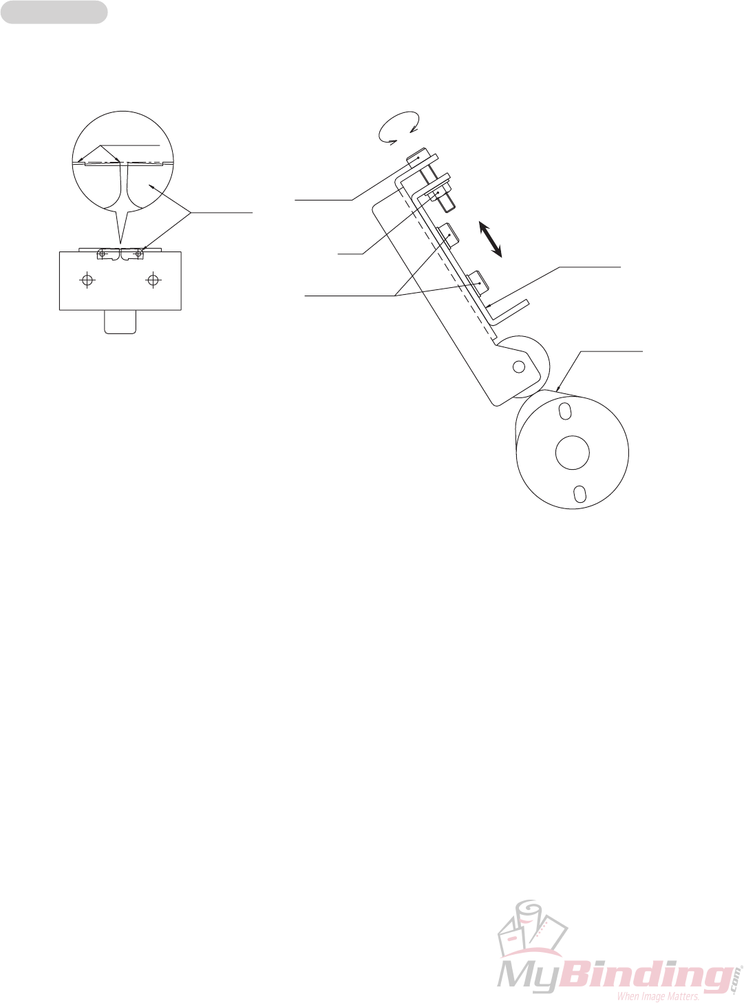
1-4. Stapler/Clincher Mechanism
The stapler unit staples the paper while the crank shaft makes one round by the DC motor, and at the same time, the
cam drives the clincher to bend the staple flat.
Adjustments
(1) Adjusting the height of the clincher
When the cam is at the top dead point, adjust so that the upper surface of the clinch plate and tip of the clincher
are of the same level.
Clinch plate
11C-2335X
CFR4 ×20
FN4
(Apply screwlock)
CFR4 ×8, W4
Cam
11C-2051X
11C-2308X
Clincher
Even ±0.2
1-5
11C-M12M0-0004-0
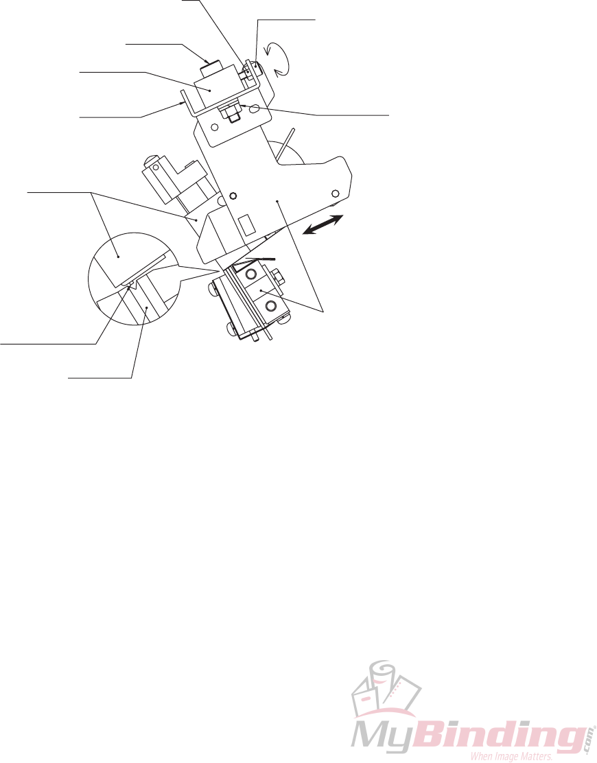
(2) Adjusting the front and back positions of the stapler unit
Adjust the position at which staples come out of the stapler unit to the groove of the clincher.
qSet the stapler unit with the staple cartridge removed and clincher at the 140 (5" 1/2) position of the indication
label.
wRotate the crank shaft to the stapling position (bottom dead point).
eLoosen the M4 nut and M6 nut.
rRotate the position adjusting screw (M4 capscrew bolt), and adjust the position of the staple guide so that the
position at which staples come out of the stapler unit (small projection) coincides with the groove of the
clincher.
tAfter completing the adjustment, tighten the M4 nut and M6 nut.
CFR4 ×20
N6, SW6, W6
CFR6 ×30
N4
Stapler unit
98R-2004X
(Small projection)
Position at which
staples come out
Clincher
11C-2308X
Move the stapler unit and
clincher to the 140 (5" 1/2)
position
Bracket
11C-2033X
Staple guide
11C-2012X
1-6
11C-M12M0-0004-0
(3) Adjusting the pushing amount of the stapler
unit
Set to the stapling position (bottom dead point) and
check the pushing amount of the stapler unit by
inserting the tool.
qRemove the M3 screws, and remove the staple
remaining detection sensor (upper side).
wSet the stapler unit with the staple cartridge removed and clincher at the 140 (5" 1/2) position of the indication
label.
eLoosen the M8 nut and M4 bolt.
rSet the stapling state (bottom dead point), and check the pushing amount of the stapler unit using the tool.
As the thickness of the tool differs between the two ends, if the thinner end fits the space while the thicker end
does not, it means it has been adjusted.
∗If both ends of the tool fit the space, rotate the adjusting screw (M4 capscrew bolt) to the left.
If both ends of the tool do not fit the space, rotate the adjusting screw to the right.
tAfter adjusting, tighten the M8 nut and M4 bolt, and attach the staple remaining detection sensor (upper side)
removed at q.
Staple remaining detection
sensor (Upper side)
M3
Stapler unit
98R-2004X
(2.6 mm)
Thicker end
(2.3 mm)
Thinner end
(Clearance gauge)
Tool
CFR4 ×20
11C-2036X
Rod
N8, SW8, W8
Staple bar unit
11C-2026X
MSKW4 ×8
1-7
11C-M12M0-0004-0
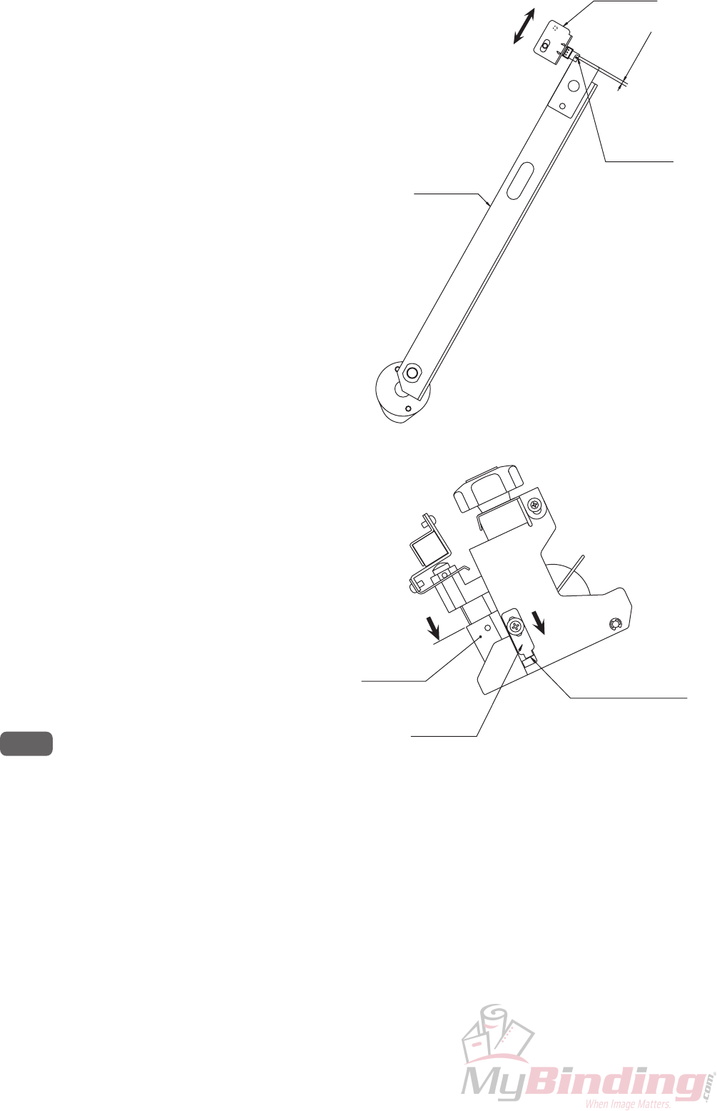
(4) Adjusting the position of the stapler home
sensor
When the rod is at the top dead point, adjust the PH
angle to the position where it blocks the optical axis
of the photointerrupter by 2 to 3 mm.
Optical axis
PH angle
11C-2040X
Rod
11C-2036X
2to3mm
(5) Adjusting the position of the stopper
To prevent mis-stapling (no staples are stapled),
adjust the stopper position so that the stapler unit
does not shake at the standby position (top dead
point).
qLoosen the screw.
wLower the stapler unit.
eLower the stopper, and fix it when it touches the
stapler.
(Fix the left and right sides at the same height.)
NOTE : If this adjustment is not complete, staples
will not be conveyed inside the stapler
unit and therefore no staples will be
stapled.
Stapler unit
98R-2004X
Stopper
98R-2006X
Touch against stapler
corner and fix
(6) Checking stapling
Set the stapler unit and clincher at the 40 (1" 5/8) position of the indication label, staple, and check the stapled
condition.
1-8
11C-M12M0-0004-0
1-5. Folding Knife/Folding Roller Mechanism
Adjustments
(1) Adjusting the sliding part of the knife base
Adjust the guide so that the knife base moves over
the sliding part smoothly without shaking.
Knife
11C-3004X
Knife base
11C-3006X
Sliding part
Screw
Guide
92W-1047X
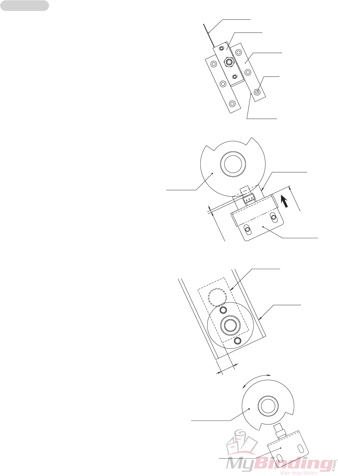
(2) Adjusting the height of the home sensor of the
folding knife
Touch the sensor bracket against the edge of the
square hole of the frame F and fix it.
(3) Adjusting the home position of the folding knife
To stop the folding knife at the lower limit position,
adjust so that the arm and crank unit are parallel,
and adjust the position of the round plate unit.
∗In the “Parts Catalog”, the crank unit is part of
the shaft unit (11C-3019X).
Sensor bracket
99J-3239X
Touch
Round plate
unit
99J-3226X
About 1 mm
Square hole of
frame F
Round plate unit
99J-3226X
Sensor bracket
99J-3239X
Parallel
Crank unit
11C-3021X
Arm
99J-3214X
1-9
11C-M12M0-0004-0
1-6. Folding Conveyance Mechanism
The flat belts sandwich and convey the paper single-folded by the folding roller.
Precautions on replacing the flat belt
Replace taking note of the rotating direction of the flat belt. (Arrow at the back of the flat belt)
Replace the flat belt in pairs.
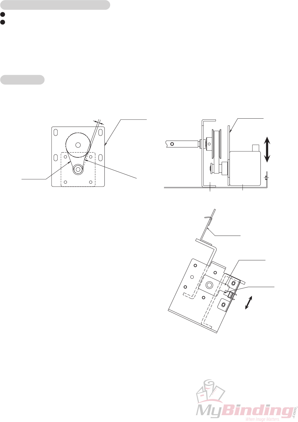
1-7. Stopper Mechanism
The timing belt moves forward and backward from the rotating movements of the stepping motor, and the stopper
moves up and down.
Adjustments
(1) Adjusting the tension of the STS belt
Adjust the position of the plate so that the belt slacks by 2 mm when a pressure of 1.96 N (200 gf) is applied.
Plate
11C-3644X
STS belt
014-10408
2mm
1.96 N (200 gf)
Plate
11C-3644X
(2) Adjusting the position of the stopper home
sensor
When the stopper ST is at the upper limit position,
adjust the photointerrupter so that the plate comes
to the position of the optical axis.
Optical axis
Stopper ST
11C-3607X
Plate
11C-3640X
1-10
11C-M12M0-0004-0
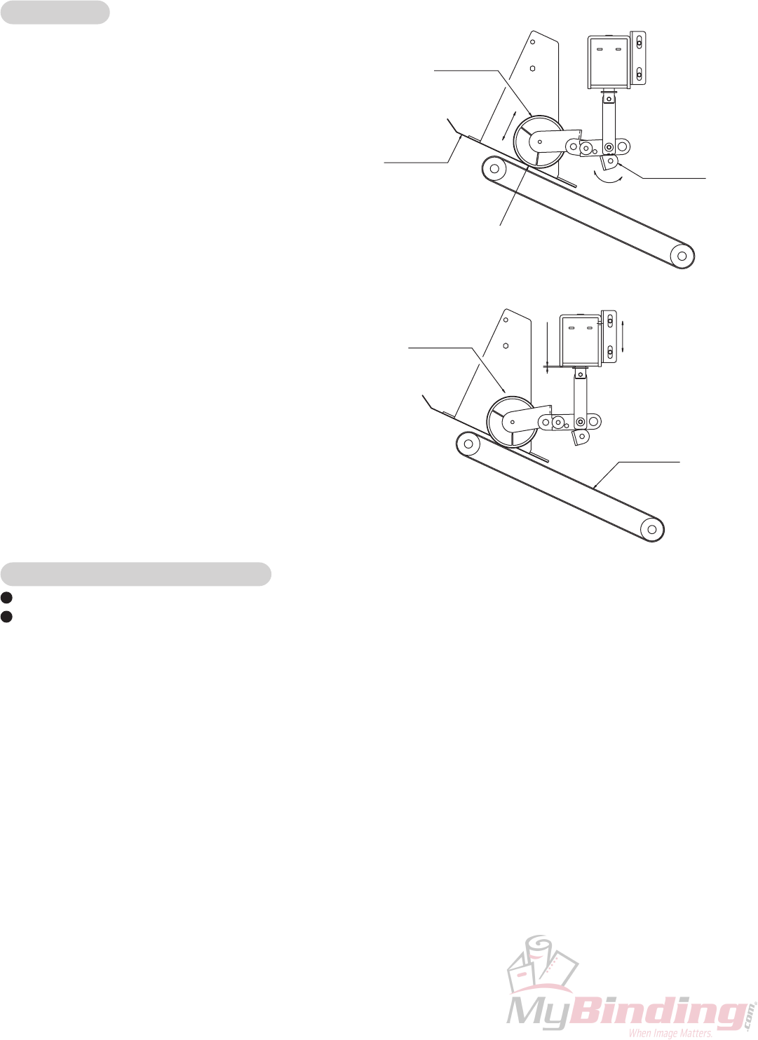
1-8. Conveyance Mechanism (Exit)
Paper is conveyed by the flat belt.
Adjustments
(1) Adjusting the standby position of the roller
Adjust the angle of the angle so that the mylar and
roller become even.
(2) Adjusting the position of the solenoid
With the roller touching the flat belt, adjust the
solenoid to the position where a 0.5 mm clearance
is formed with the plunger.
Precautions on replacing the flat belt
Replace taking note of the rotating direction of the flat belt. (Arrow at the back of the flat belt)
Replace the flat belt in pairs.
Flat belt
11C-4505X
Roller
98H-4347X
0.5 mm
Angle
952-1438X
Mylar
11C-6074X
Roller
98H-4347X
Even

1-11
11C-M12M0-0004-0
2. MAINTENANCE
Clean the following parts
Rubber roller
Resin roller
Flat belt
Folding roller
Index plate
Photointerrupter
Main unit
Remote unit
Switching power supply
Oil the following parts (Equivalent to Nisseki Mitsubishi Co. Ld. FBK oil R028)
Sintering bearing
Link rotating fulcrum of the solenoid
Grease the following parts (Equivalent to Dowconning Co. Ld. MOLY KOTE X5-6020)
Stapler head
Where the flat cogwheels are engaged
Where the worm gears are engaged
Clincher mechanism sliding part
Folding knife sliding part
Folding roller sliding part
Resin idler (Apply to center pin)
Grease the following parts (Equivalent to Kyodoyushi Co. Ld. uniloob No.2)
Chain
Grease the following parts (Equivalent to Orelube G90-140 oil)
Driving plate (Apply a thin layer only to the part sliding over the clincher)

This page is a blank page.

2-1
11C-M12M0-0004-0
CHAPTER 2
ELECTRICAL COMPONENTS
1. Block Diagram of Structure and Outline of
Each Block ...................................................... 2-2
1-1. MC Unit .................................................. 2-5
1-2. OP Unit (Control Panel) ......................... 2-5
1-3. Staple Motor .......................................... 2-5
1-4. Knife Motor ............................................ 2-5
1-5. Folding Conveyance Motor .................... 2-5
1-6. Conveyance Motor.................................2-5
1-7. Cover Switch..........................................2-5
1-8. Movable Table Motor ............................. 2-5
1-9. Back Jogger Unit Motor .........................2-5
1-10. Stopper Unit Motor.................................2-6
1-11. Stopper Motor ........................................2-6
1-12. Stopper Home Sensor ........................... 2-6
1-13. Stopper Paper Switch ............................ 2-6
1-14. Side Jogger Motor ................................. 2-6
1-15. Back Jogger Motor.................................2-6
1-16. Back Jogger Home Sensor .................... 2-6
1-17. Back Jogger Paper Sensor .................... 2-6
1-18. Side-stapling Paper Ejection Solenoid...2-6
1-19. Stacker Connection Connector .............. 2-6
1-20. Stacker Motor ........................................ 2-6
1-21. Side-stapling Gate Solenoid .................. 2-6
1-22. Conveyance Clutch................................2-7
1-23. Total Counter .........................................2-7
1-24. Staple Home Sensor..............................2-7
1-25. Movable Table Home Sensor ................ 2-7
1-26. Knife Home Sensor................................2-7
1-27. Staple Index Sensor .............................. 2-7
1-28. Knife Index Sensor ................................ 2-7
1-29. Folding Conveyance Index Sensor ........ 2-7
1-30. Conveyance Index Sensor.....................2-7
1-31. Option Sensor ........................................ 2-7
1-32. Back Unit Home Sensor ........................ 2-7
1-33. Stopper Unit Home Sensor .................... 2-8
1-34. Side Jogger Home Sensor.....................2-8
1-35. Staple Paper Switch .............................. 2-8
1-36. Saddle-stapling Paper Ejection Paper
Switch .................................................... 2-8
1-37. Side-stapling Paper Ejection Paper
Switch .................................................... 2-8
1-38. No-staple R Sensor ............................... 2-8
1-39. No-staple L Sensor ................................ 2-8
1-40. Switching Power Supply ........................ 2-8
1-41. Remote Unit (RM Unit) .......................... 2-8
1-42. Power Supply Switch .............................2-8
1-43. Main Power Switch ................................ 2-9
1-44. Power Supply Inlet ................................. 2-9
1-45. Module Connector 1 .............................. 2-9
1-46. Module Connector 2 .............................. 2-9
1-47. LED 1 (Green) ....................................... 2-9
1-48. LED 2 (Orange) ..................................... 2-9
1-49. IF Cable ................................................. 2-9
1-50. Power Cord ............................................ 2-9
2. Errors and Causes .......................................... 2-10
2-1. When Paper Jams Occur.......................2-10
2-2. Troubleshooting ..................................... 2-12
2-3. Other Condition Messages .................... 2-16
3. Maintenance Mode ......................................... 2-17
3-1. Entering the Maintenance Mode ............ 2-17
3-2. ROM Version Display ............................ 2-17
3-3. Simulation Mode .................................... 2-17
3-4. Sensor Check Mode .............................. 2-18
3-5. Motor/Solenoid Test Mode.....................2-18
3-6. Changing the Display Language............2-18
3-7. Changing the Paper Reference ............. 2-18
4. Precautions on Replacing the MC Unit ........... 2-19
5. Precautions on Replacing Fuses .................... 2-20
6. LCD Map ......................................................... 2-21
6-1. LCD Map (Normal Menu).......................2-21
6-2. LCD Map (Maintenance Mode)..............2-24
7. Overall Schematic Diagram ............................ 2-27
8. Wiring Diagram ............................................... 2-28
2-2
11C-M12M0-0004-0
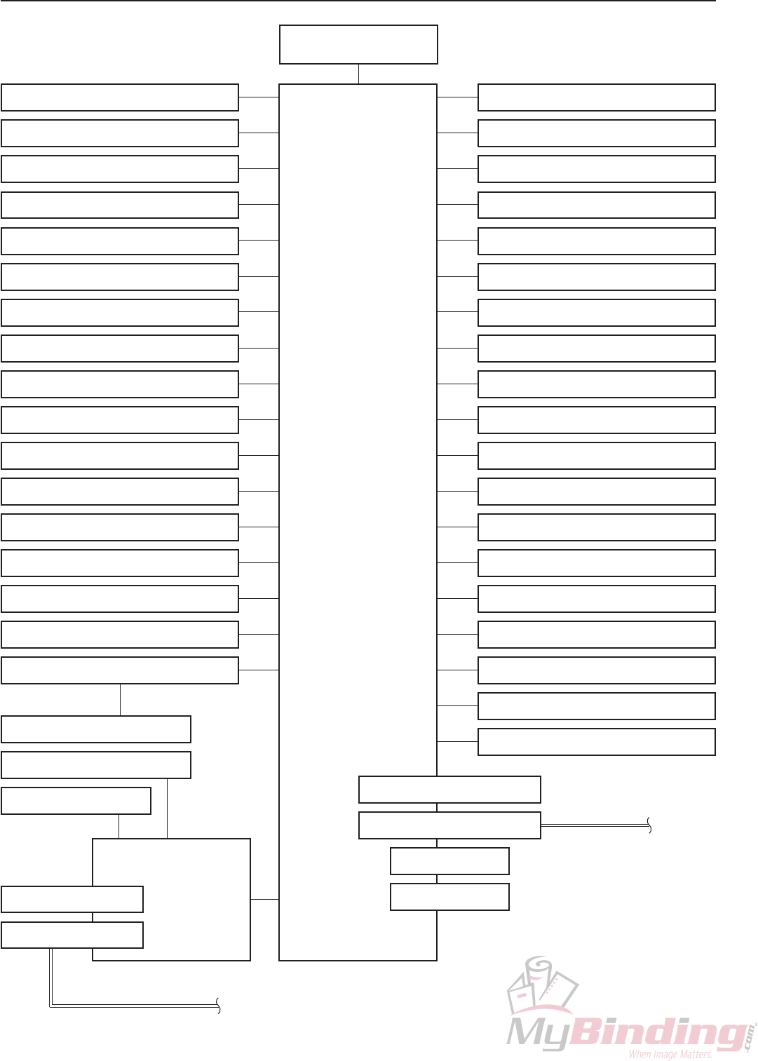
1. BLOCK DIAGRAM OF STRUCTURE AND OUTLINE OF EACH BLOCK
1-3. Staple motor 1-21. Side-stapling gate solenoid
1-2. OP unit
(Control panel)
1-1. MC unit
1-4. Knife motor
1-5. Folding conveyance motor
1-6. Conveyance motor
1-7. Cover switch
1-8. Movable table motor
1-9. Back jogger unit motor
1-10. Stopper unit motor
1-11. Stopper motor
1-12. Stopper home sensor
1-13. Stopper paper switch
1-14. Side jogger motor
1-15. Back jogger motor
1-16. Back jogger home sensor
1-17. Back jogger paper sensor
1-18.
Side-stapling paper ejection solenoid
1-19. Stacker connection connector
1-22. Conveyance clutch
1-23. Total counter
1-24. Staple home sensor
1-25. Movable table home sensor
1-26. Knife home sensor
1-27. Staple index sensor
1-28. Knife index sensor
1-29. Folding conveyance index sensor
1-30. Conveyance index sensor
1-31. Option sensor
1-32. Back unit home sensor
1-33. Stopper unit home sensor
1-34. Side jogger home sensor
1-35. Staple paper switch
1-36.
Saddle-stapling paper ejection paper switch
1-37
.
Side-stapling paper ejection paper switch
1-38. No-staple R sensor
1-39. No-staple L sensor
1-20. Stacker motor
1-40. Switching power supply
1-42.
Power supply switch
1-45. Module connector 1
1-43.
Main power switch
1-44.
Power supply inlet
(When not connected to
the trimmer)
1-46. Module connector 2
1-47. LED 1
1-48. LED 2
1-41. Remote unit
(RM unit)
1-50. Power cord
1-49. IF cable To trimmer
2-3
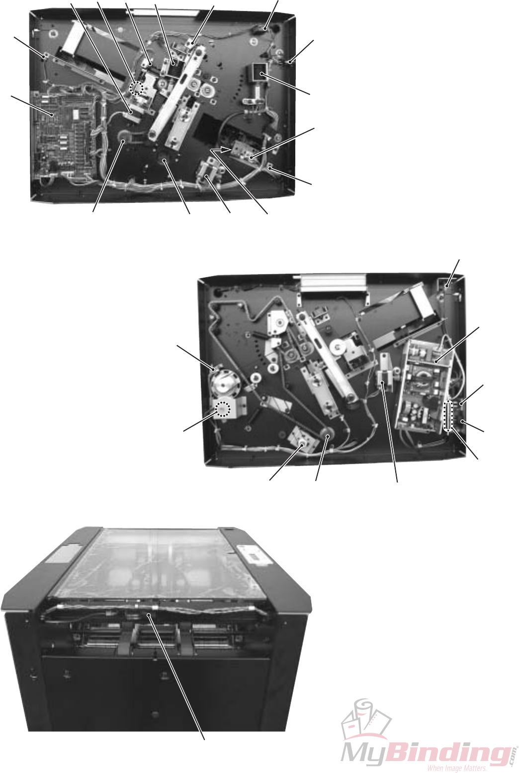
11C-M12M0-0004-0
1-24
1-19
1-30
1-32
1-6
1-42
1-7
1-21
1-31
1-14 1-34 1-23
1-18
1-12
1-33
1-10
1-4 1-11
1-1
1-3
1-22
1-5 1-9
1-40
1-43
1-44
1-41
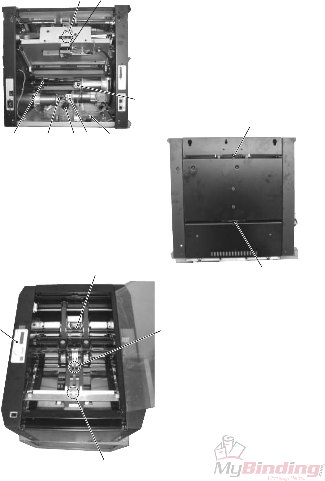
2-4
11C-M12M0-0004-0
1-16 1-15
1-27
1-25
1-28
1-8
1-29
1-26
1-36
1-37
1-13
1-35
1-17
1-2

2-5
11C-M12M0-0004-0
1-1. MC Unit
The MC unit controls the whole machine by the 8-bit microprocessor. It also incorporates a stepping motor, DC motor,
and solenoid driving circuit. It has a built-in DC converter which generates +5 V with the DC +24 V power supply input.
A DC +5 V power supply is used for ICs and sensors while a DC +24 V is used for driving the motor and solenoid.
The board is mounted with six microprocessors and one ROM. Of the six microprocessors, one is for main control,
three for controlling the stepping motors, one for controlling communication with the control panel, and the remaining
one for controlling communication other than the control panel. One stepping motor control microprocessor is used for
controlling two stepping motors. The ROM is a 128K-byte EPROM written with the main control program. The
stepping motor control program and communication control program are written in the built-in ROM of the respective
microprocessors. The MC unit is connected with the OP unit (control panel) by communication.
1-2. OP Unit (Control Panel)
The control panel is controlled by a one-chip 8-bit microprocessor. It is mounted with a 16-character 2-line liquid
crystal display and a jog dial. The control program is written in the built-in ROM of the microprocessor. It is connected
with the MC unit by communication.
1-3. Staple Motor
DC +24 V power supply brush motor. Drives the stapler.
1-4. Knife Motor
DC +24 V power supply brush motor. Drives the folding knife.
1-5. Folding Conveyance Motor
DC +24 V power supply brush motor. Drives the folding rollers and folding conveyance section.
1-6. Conveyance Motor
DC +24 V power supply brushless motor. Drives the main conveyance section.
1-7. Cover Switch
Normal open microswitch. When the cover is closed, contact is established. This switch is connected to the control
coil of the relay mounted to the MC unit. The contact of this relay is connected with the DC +24 V supplied to the staple
motor, knife motor, folding conveyance motor, and conveyance motor. As it is connected in this way, operating the
microswitch opens and closes the relay contact. When the top cover is opened, the DC +24 V supplied to the staple
motor, knife motor, folding conveyance motor, and conveyance motor is cut off.
1-8. Movable Table Motor
DC +24 V power supply brush motor. When the paper reference is set to “Center”, this motor drives the machine and
automatically adjusts it to the position of the upstream processing unit.
1-9. Back Jogger Unit Motor
DC +24 V power supply stepping motor. Moves the back jogger unit incorporating the back jogger.

2-6
11C-M12M0-0004-0
1-10. Stopper Unit Motor
DC +24 V power supply stepping motor. Moves the stopper unit incorporating the stapling/folding stoppers.
1-11. Stopper Motor
DC +24 V power supply stepping motor. Drives the stapling/folding stoppers.
1-12. Stopper Home Sensor
Sensor for detecting the home positions of the stapling/folding stoppers. Uses a photointerrupter.
1-13. Stopper Paper Switch
Normal closed switch. Used for detecting paper tip and jams caused by paper remaining in the machine.
1-14. Side Jogger Motor
DC +24 V power supply stepping motor. Motor for driving the side jogger.
1-15. Back Jogger Motor
DC +24 V power supply stepping motor. Motor for driving the back jogger.
1-16. Back Jogger Home Sensor
Sensor for detecting the home position of the back jogger. Uses a photointerrupter.
1-17. Back Jogger Paper Sensor
Sensor for detecting paper tip and jams caused by paper remaining in the machine. Uses a photointerrupter.
1-18. Side-stapling Paper Ejection Solenoid
Solenoid for driving the rollers at the top of the stapling/folding stopper section. Uses a DC +24 V power.
1-19. Stacker Connection Connector
When the trimmer is not connected, connects the stacker unit.
1-20. Stacker Motor
Motor for driving the belt of the stacker unit. Uses a DC +24 V power.
1-21. Side-stapling Gate Solenoid
Solenoid for driving the stoppers for side-stapling and corner-stapling. Uses a DC +24 V power.

2-7
11C-M12M0-0004-0
1-22. Conveyance Clutch
Electromagnetic clutch for transmitting the conveyance force to the stapling/folding stopper section. Uses a DC +24 V
power.
1-23. Total Counter
Electromagnetic counter. Uses a DC +24 V power. Counts up with each stapling/folding or folding operation.
1-24. Staple Home Sensor
Sensor for detecting the home position of the stapler. Uses a photointerrupter.
1-25. Movable Table Home Sensor
Sensor for detecting the home position of the machine moving mechanism (Movable table). Uses a photointerrupter.
1-26. Knife Home Sensor
Sensor for detecting the home position of the folding knife. Uses a photointerrupter.
1-27. Staple Index Sensor
Uses a photointerrupter. When the staple motor rotates and the notch of the index plate attached to the motor shaft
passes by the sensor, the sensor outputs pulses at a fixed cycle.
Used for detecting the rotation of the staple motor.
1-28. Knife Index Sensor
Uses a photointerrupter. When the knife motor rotates and the notch of the index plate attached to the motor shaft
passes by the sensor, the sensor outputs pulses at a fixed cycle.
Used for detecting the rotation of the knife motor.
1-29. Folding Conveyance Index Sensor
Uses a photointerrupter. When the folding conveyance motor rotates and the notch of the index plate attached to the
motor shaft passes by the sensor, the sensor outputs pulses at a fixed cycle.
Used for detecting the rotation of the folding conveyance motor.
1-30. Conveyance Index Sensor
Uses a photointerrupter. When the conveyance motor rotates and the notch of the index plate passes by the sensor,
the sensor outputs pulses at a fixed cycle.
Used for detecting the rotation of the conveyance motor.
1-31. Option Sensor
Sensor for detecting the optional guides. Uses a photointerrupter.
1-32. Back Unit Home Sensor
Sensor for detecting the home position of the back jogger unit. Uses a photointerrupter.

2-8
11C-M12M0-0004-0
1-33. Stopper Unit Home Sensor
Sensor for detecting the home position of the stopper unit. Uses a photointerrupter.
1-34. Side Jogger Home Sensor
Sensor for detecting the home position of the side jogger. Uses a photointerrupter.
1-35. Staple Paper Switch
Normal closed switch. Used for detecting paper tip, end, and jams caused by paper remaining in the machine.
1-36. Saddle-stapling Paper Ejection Paper Switch
Normal closed switch. Located at the top of the paper ejection slot for folding and stapling/folding, used for detecting
paper tip, end, and jams caused by paper remaining in the machine.
1-37. Side-stapling Paper Ejection Paper Switch
Normal closed switch. Located at the top of the paper ejection slot for ejecting paper, side-stapling, and corner-
stapling, used for detecting paper tip, end, and jams caused by paper remaining in the machine.
1-38. No-staple R Sensor
Sensor for detecting the remaining staple in the stapler on the right in the direction in which the paper moves.
1-39. No-staple L Sensor
Sensor for detecting the remaining staple in the stapler on the left in the direction in which the paper moves.
1-40. Switching Power Supply
Outputs DC +24 V. Mounted with a 6.3 A fuse.
Used also for 100 V, 120 V, 220 to 240 V, and 50/60 Hz.
Incorporates a protection circuit for overcurrent and overvoltage. If the protection circuit turns on due to some reason,
turn OFF the power, wait 3 minutes before turning it ON again.
1-41. Remote Unit (RM Unit)
When machines with remote functions are connected, the remote unit is able to turn ON and OFF the power of the two
machines using an interface cable. Mounted with a 6.3 A fuse.
Incorporates an internal inlet (for supplying power) and main power switch.
1-42. Power Supply Switch
Used to turn ON/OFF the power supply using the remote unit. Even if this switch is set to OFF, the power supplied to
the inside of the machine will not be cut off.
When connecting with a downstream processing unit with remote function, the power of the downstream processing
unit will also turn ON simultaneously.

2-9
11C-M12M0-0004-0
1-43. Main Power Switch
Incorporated in the remote unit. Used to turn ON/OFF the power supply of the machine.
1-44. Power Supply Inlet
Incorporated in the remote unit. Connected to the power cord.
1-45. Module Connector 1
Connector for communication with the machine connected. When performing communication from the upstream
processing unit, insert an interface cable.
1-46. Module Connector 2
Connector for communication with the machine connected. When performing communication to the downstream
processing unit, insert an interface cable.
1-47. LED 1 (Green)
Lights up in green when power is supplied to the machine.
1-48. LED 2 (Orange)
Lights up only when the remote function is effective and the power is supplied from the upstream processing unit.
1-49. IF Cable
Interface cable for communication with the downstream processing unit.
1-50. Power Cord
Supplies primary power to the machine.
2-10
11C-M12M0-0004-0
Display in 2nd Line Conveyance Route
In Paper Conveyer
In Stapler
In Folder
Paper conveyer
section
Stapler section
Folder section
From upstream processing unit paper ejection to back jogger
paper sensor, or from back jogger paper sensor to side-stapling
paper ejection paper switch
From back jogger paper sensor to staple paper switch, or from
staple paper switch to stopper paper switch
From stopper paper switch to saddle-stapling paper ejection paper
switch
Place
Jam codes
Jam Code
Description
J1
J2
J3
J4
J5
J6
J7
J8
J9
J10
J11
J12
Not reaching back jogger
section
Not reaching side-stapling
paper ejection section and
remaining in stopper
section
Not reaching side-stapling
paper ejection section
Remaining in back jogger
section
Not reaching stapler
section
Remaining in stapler
section
Not reaching stopper
section
Remaining in stopper
section
Not reaching saddle-
stapling paper ejection
section
Remaining in saddle-
stapling paper ejection
section
No setting
Remaining in side-stapling
paper ejection section
After receiving paper ejection signal of the upstream processing unit,
paper does not reach back jogger paper sensor within specified time.
After paper reaches back jogger paper sensor, paper does not reach
side-stapling paper ejection paper switch even after the specified time.
There is also paper remaining in the stopper paper switch.
After paper reaches back jogger paper sensor, paper does not reach
side-stapling paper ejection paper switch even after the specified time.
There is paper remaining on the back jogger paper sensor even after the
specified time.
The paper does not reach the staple paper switch even after the
specified time after the paper end passes the back jogger paper sensor.
There is paper remaining in the staple paper switch even after the
specified time after the stopper has been lowered.
The paper does not reach the stopper paper switch even after the
specified time after the stopper has been lowered.
There is paper remaining on the stopper paper switch even after the
specified time after the folding knife has been turned ON.
The paper does not reach the saddle-stapling paper ejection paper
switch even after the specified time after the folding knife has been
turned ON.
There is paper remaining on the saddle-stapling paper ejection paper
switch even after the specified time.
No setting
There is paper remaining on the side-stapling paper ejection paper
switch even after the specified time.
Name of Jam
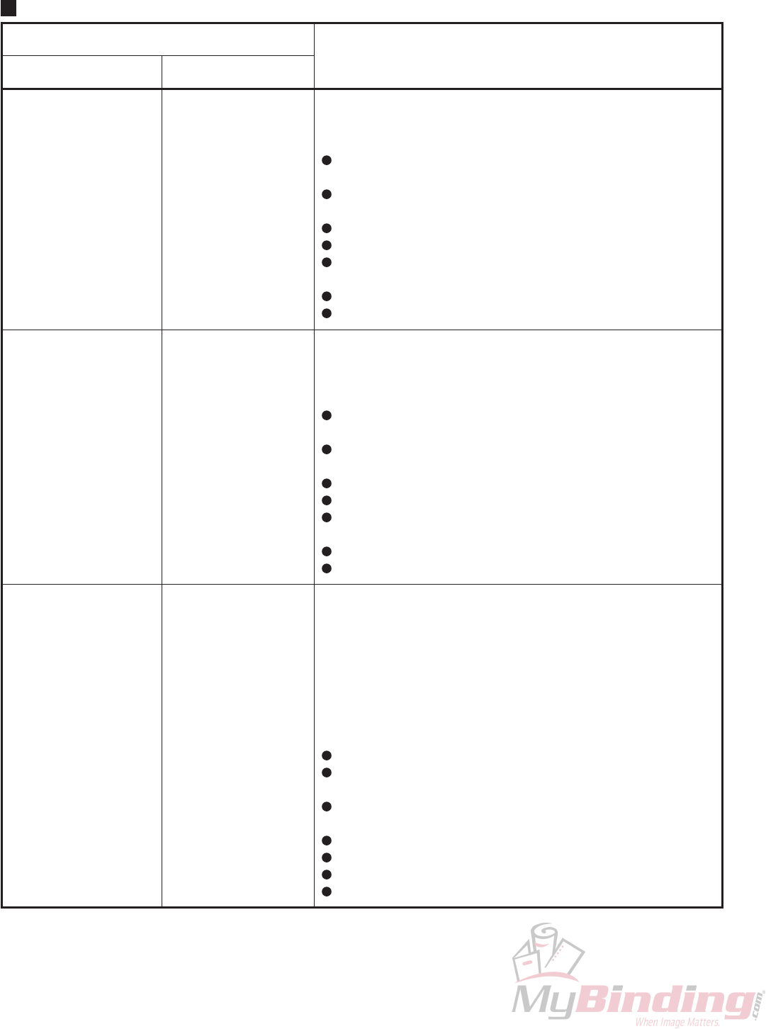
2. ERRORS AND CAUSES
2-1. When Paper Jams Occur
The first line of the LCD on the control panel displays “Paper Jam”. The second line displays “In Paper Conveyer”
(paper conveyer section), “In Stapler” (stapler section), or “In Folder” (folder section) according to where the paper
has jammed. Turning the jog dial displays the jam code on the next screen. Refer to the following table.
Place of paper jam

2-11
11C-M12M0-0004-0
NOTE : The following causes may be suspected if jam codes are displayed even though no paper jam has actually
occurred.
The lever of the paper switch does not return
There are paper bits or foreign objects jammed on the paper switch
The paper switch is faulty
The connection between the paper switch and MC unit is faulty
The MC unit is faulty
2-12
11C-M12M0-0004-0
Display in 2nd Line Description
Feed Motor
Fold Feed Motor
Knife Motor
Trouble
Trouble
Home-Out Trouble
Home-In Trouble
Index Trouble
The output of the conveyance motor index sensor is not normal.
<Causes>
Overload and restriction of the conveyance system
mechanism
Foreign objects jammed in the detecting section of the index
sensor.
Faulty connection between the index sensor and MC unit
Malfunction of the index sensor
Faulty connection between the conveyance motor and MC
unit
Malfunction of the MC unit
Malfunction of the conveyance motor
The output of the folding conveyance motor index sensor is not
normal.
<Causes>
Overload and restriction of the folding conveyance system
mechanism
Foreign objects jammed in the detecting section of the index
sensor.
Faulty connection between the index sensor and MC unit
Malfunction of the index sensor
Faulty connection between the folding conveyance motor and
MC unit
Malfunction of the MC unit
Malfunction of the folding conveyance motor
The home sensor does not turn OFF (penetrating) within the
specified time after the motor has turned ON.
The home sensor does not turn ON (blocking) within the
specified time after the motor has turned ON.
The output of the knife index sensor is not normal.
<Common causes>
Overload and restriction of the folding knife mechanism
Foreign objects jammed in the detecting section of the index
sensor.
Faulty connection between the index sensor, home sensor
and MC unit
Malfunction of the index sensor, home sensor
Faulty connection between the knife motor and MC unit
Malfunction of the MC unit
Malfunction of the knife motor
(First Half) (Second Half)
---------------------------------------------------------------------------
---------------------------------------------------------------------------
-------------------------------------------------------------------------------------------------------
-------------------------------------------------------------------------------------------------------
-------------------------------------------------------------------------------------------------------
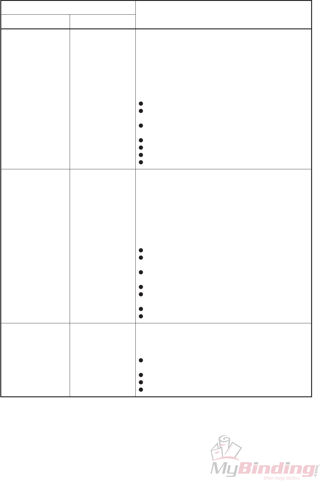
2-2. Troubleshooting
When a problem occurs, the first line of the message on the LCD of the control panel will display “Malfunction”. The
second line will display the name of the problem. Details are provided below.
Details of problems (1/2)
2-13
11C-M12M0-0004-0
Display in 2nd Line Description
Stapler Motor
Machine Move Motor
Stacker Motor
Home-Out Trouble
Home-In Trouble
Index Trouble
Home-Out Trouble
Home-In Trouble
Index Trouble
Trouble
The home sensor does not turn OFF (penetrating) within the
specified time after the motor has turned ON.
The home sensor does not turn ON (blocking) within the
specified time after the motor has turned ON.
The output of the stapler index sensor is not normal.
<Common causes>
Overload and restriction of the stapler mechanism
Foreign objects jammed in the detecting section of the index
sensor.
Faulty connection between the index sensor, home sensor
and MC unit
Malfunction of the index sensor, home sensor
Faulty connection between the stapler motor and MC unit
Malfunction of the MC unit
Malfunction of the stapler motor
The home sensor does not turn OFF (penetrating) within the
specified time after the motor has turned ON.
The home sensor does not turn ON (blocking) within the
specified time after the motor has turned ON.
The output of the movable table motor index sensor is not
normal.
<Common causes>
Overload and restriction of the movable table mechanism
Foreign objects jammed in the detecting section of the index
sensor.
Faulty connection between the index sensor, home sensor
and MC unit
Malfunction of the index sensor, home sensor
Faulty connection between the movable table motor and MC
unit
Malfunction of the MC unit
Malfunction of the movable table motor
The overcurrent detection of the stacker motor drive circuit
operates.
<Causes>
Overload and restriction of the stacker, paper ejection
mechanism
Faulty connection between the stacker motor and MC unit
Malfunction of the stacker motor
Malfunction of the MC unit
(First Half) (Second Half)
-------------------------------------------------------------------
-------------------------------------------------------------------------------------------------------
-------------------------------------------------------------------------------------------------------
-------------------------------------------------------------------------------------------------------
-------------------------------------------------------------------------------------------------------
-------------------------------------------------------------------------------------------------------
-------------------------------------------------------------------------------------------------------
2-14
11C-M12M0-0004-0
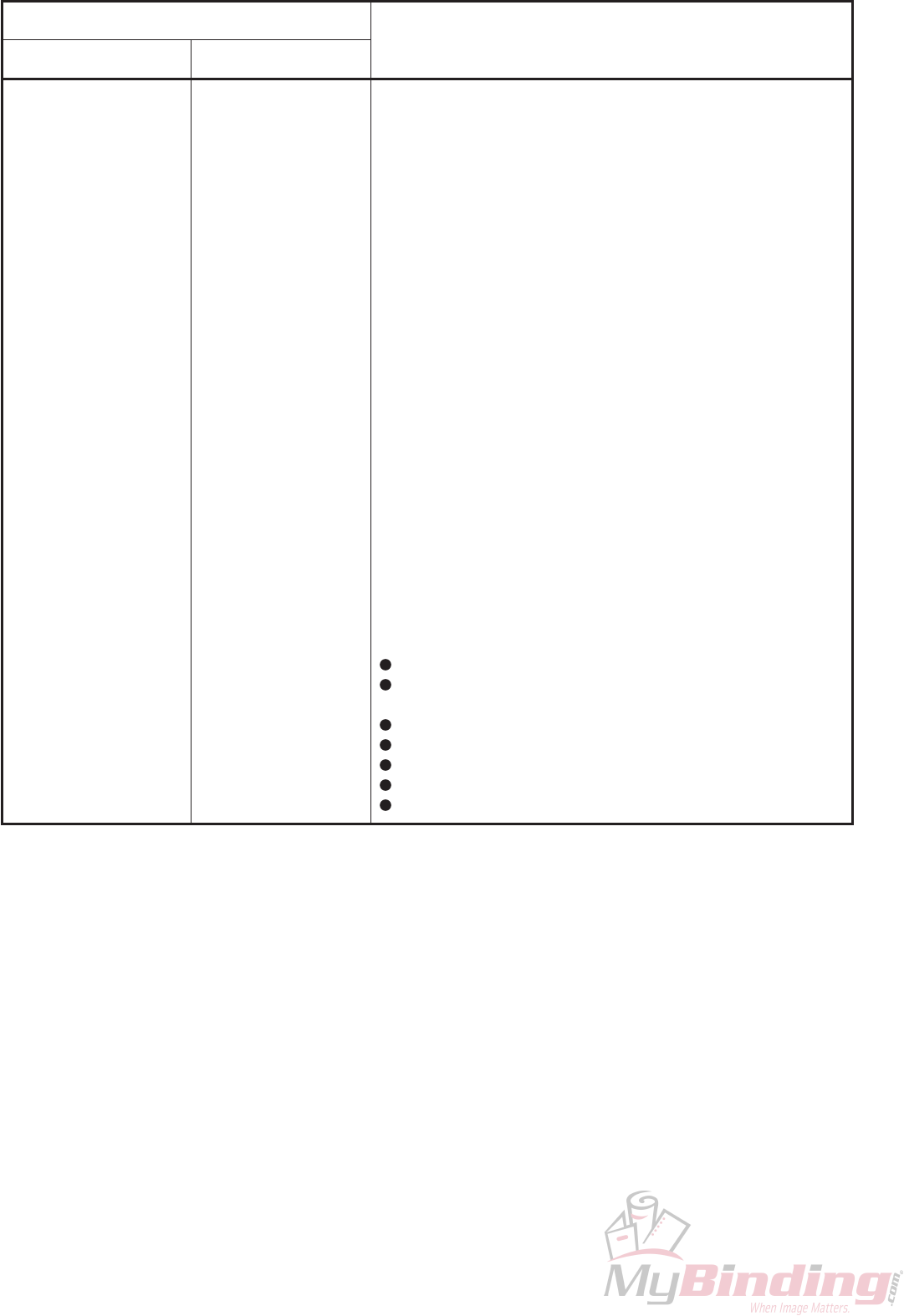
Display in 2nd Line Description
∗∗ Motor
∗∗: Side Jog,
Back Jog,
Back Jog Unit,
Stopper Unit,
Stopper
Home-In Trouble
Home-Out Trouble
Home-Out/In Trouble
Counter-Out Trouble
Counter-In Trouble
When the home sensor is OFF (penetrating), the motor turned
ON for moving ∗∗ to the direction towards the home, but the
home sensor does not turn ON (blocking) within the specified
time.
When the home sensor is ON (blocking), the motor turned ON
for moving ∗∗ to the direction away from the home, but the home
sensor does not turn OFF (penetrating) within the specified
time.
When the home sensor is ON (blocking), after the motor turned
ON for moving ∗∗ to the direction away from the home, the
motor reversed. At this time, the sensor does not turn ON again
within the specified time.
After ∗∗ has been moved for a certain distance away from the
home, and was moved back for the same distance, it reached
the home and proceeded forwarded more than the specified
distance. (The motor was out of step in the movement away
from the home.)
After ∗∗ has been moved for a certain distance away from the
home, and was moved back for the same distance, it does not
return to the home. When the ∗∗ is moved for the specified
distance again, it does not return to the home. (The motor was
out of step in the movement towards the home.)
<Common causes>
Overload and restriction of the ∗∗ unit moving mechanism
Foreign objects jammed in the detecting section of the home
sensor.
Faulty connection between the home sensor and MC unit
Malfunction of the home sensor
Faulty connection between the motor and MC unit
Malfunction of the MC unit
Malfunction of the motor
(First Half) (Second Half)
-------------------------------------------------------------------------------------------------------
-------------------------------------------------------------------------------------------------------
-------------------------------------------------------------------------------------------------------
-------------------------------------------------------------------------------------------------------
-------------------------------------------------------------------------------------------------------
2-15
11C-M12M0-0004-0
Details of problems (2/2)
Display in 2nd Line Description
Motor MPU ∗ CRC Error
∗: 1, 2, 3
Motor MPU ∗ ACK Error
∗: 1, 2, 3
Panel MPU ∗∗∗ Error
∗∗∗: CRC, ACK
Panel Interface MPU Error
Internal Interface MPU Error
Interface ∗∗∗ Error
∗∗∗: CRC, ACK
Memory Data Error
Memory Write ACK Error
DA Converter ACK Error
Communication error between the stepping motor control microprocessor
and main control microprocessor in the MC unit
<Cause>
Malfunction of the MC unit
Communication error between the stepping motor control microprocessor
and main control microprocessor in the MC unit
<Cause>
Malfunction of the MC unit
Communication error between the MC unit and OP unit (panel)
<Causes>
Faulty connection between the OP unit and MC unit
Malfunction of the OP unit
Malfunction of the MC unit
Communication error between the control microprocessor for panel
communication and main control microprocessor in the MC unit
<Cause>
Malfunction of the MC unit
Communication error between the control microprocessor for I2C (other
than panel) communication and main control microprocessor in the MC unit
<Cause>
Malfunction of the MC unit
Not setting
Memory error and communication error in the MC unit
<Cause>
Malfunction of the MC unit
-------------------------------------------------------------------------------------------
-------------------------------------------------------------------------------------------
-------------------------------------------------------------------------------------------
-------------------------------------------------------------------------------------------
-------------------------------------------------------------------------------------------
-------------------------------------------------------------------------------------------
2-16
11C-M12M0-0004-0
Display Description
Top Cover Open
Trimmer Error
Staple ∗ Nearly Empty
∗: L, R, (Blank)
The contact of the cover switch is open.
<Other causes>
The door is not closed completely.
Malfunction of the switch
Faulty connection between the switch and MC unit
Malfunction of the MC unit
An error signal was received from the trimmer.
<Other causes>
Jam occurred at the trimmer.
The top cover of the trimmer is open.
An error other than jamming occurred at the trimmer.
Faulty connection between the trimmer and MC unit
Malfunction of the MC unit
Malfunction of the trimmer
The staples in the stapler ∗ are running out.
<Other causes>
Faulty connection between the stapler ∗ and MC unit
Malfunction of the stapler ∗
Malfunction of the MC unit
-------------------------------------------------------------------------------------------
-------------------------------------------------------------------------------------------
-------------------------------------------------------------------------------------------
2-3. Other Condition Messages
The control panel also displays messages of other conditions of the machine such as when a door is opened, etc. The
causes of such messages are shown below. In some cases, if the message and actual condition differ such as when
“Top Cover Open” is displayed despite the door being closed, an error may be suspected. Details are provided below.
Condition display

2-17
11C-M12M0-0004-0
Start button
Stop button
button
Clear
button
Escape
Jog dial/Enter button
Power ON indicator
Lights up when the stapler
folder is turned ON.
Display
button
Function
3. MAINTENANCE MODE
3-1. Entering the Maintenance Mode
Press the escape button once on the initial screen of the control panel. Turn the jog dial by three clicks towards the
right, “Number of Sheets” will be displayed. Press the clear button here once. A beep will be sounded.
Turn the jog dial by 5 clicks towards the left, “Fine Adjustment” will be displayed. Press the clear button here once. A
beep will be sounded.
After “Maintenance Menu” is displayed, press the jog dial once. Two beeps will be sounded.
The maintenance menu has four modes for selection – ROM version display, simulation mode, sensor check mode,
and motor/solenoid test mode.
3-2. ROM Version Display
Select ROM version display from the maintenance menu. The control program version of the MC unit, stepping motor
driver (SPM), or OP unit will be displayed.
3-3. Simulation Mode
When the simulation mode is selected from the maintenance menu, “Simulation Mode” will be displayed. Before
starting the simulation mode, be sure to remove the staple cartridge from the stapler.
Press the start button to start the machine in the simulation mode, and stop with the stop button.
In the simulation mode, each mechanism operates without paper.

2-18
11C-M12M0-0004-0
3-4. Sensor Check Mode
When the sensor check mode is selected from the maintenance menu, “Sensor Check” will be displayed. Turn the jog
dial to display the name of the sensor to be checked. The name can be checked as shown in the following examples.
(Example 1) To check the back jogger paper sensor
Pushing down the switch lever sets the display to “on”.
Display: “B. Jogger PSW on”
Returning the switch lever sets the display to “off”.
Display: “B. Jogger PSW off”
(Example 2) To check the conveyance index sensor (photointerrupter)
If something is blocking the detecting section of the sensor, the display will be set to “on”.
Display: “Feed Index on”
If nothing is blocking the detecting section of the sensor, the display will be set to “off”.
Display: “Feed Index off”
3-5. Motor/Solenoid Test Mode
When the motor/solenoid test mode is selected from the maintenance menu, “Motor Sol. Test” will be displayed.
Turn the jog dial to display the name of the motor or solenoid to be tested.
Press the start button to turn on the motor or solenoid selected. Press the stop button to turn them off. For the side
jogger motor, back jogger unit motor, back unit motor, stopper unit motor, and stopper gate motor, forward and
backward operations will be repeated until the position of the smallest paper size from the home position.
3-6. Changing the Display Language
When the language is selected from the maintenance menu, “Select Language” will be displayed. Turn the jog dial to
select the language used and press the jog dial to confirm the language. To activate this setting, the power needs to
be turned off and then on again.
3-7. Changing the Paper Reference
Normally do not change this setting. When the paper reference selection is selected from the maintenance menu,
“Select Paper Ref” will be displayed. Turn the jog dial to select “Center” or “Side”. To activate this setting, the power
needs to be turned off and then on again.

2-19
11C-M12M0-0004-0
4. PRECAUTIONS ON REPLACING THE MC UNIT
Fine adjustment data and customized sizes are registered in the EEPROM (nonvolatile memory) on the MC unit
(board). Therefore previous data will be lost when the MC unit is replaced. Note down the fine adjustment data and
customized sizes prior to replacement and input them after replacement. Also be sure to perform the following
procedures and checks after replacement.
(1) Initializing the memory
Turn on the power with the function button pressed. Keep pressing until initialization of the machine ends.
This procedure initializes data registered in the EEPROM (nonvolatile memory) on the MC unit (board).
(2) Checking the paper reference setting
Check the setting of the paper reference in the maintenance menu. If the setting at “Select Paper Ref” is not
appropriate, set it again. (Refer to “3-7. Changing the Paper Reference”)
(3) Checking the fine adjustment data
Enter the fine adjustment mode and check the fine adjustment data. For settings other than 0, +1 to +9, –1 to –9,
the fine adjustment data memory will need to be initialized. Perform the following procedure to initialize. Turn off
the power, and while pressing the center button (function button) on the control panel, turn on the power again.
After this, enter the fine adjustment mode. Even if there is no need to set the fine adjustment data, be sure to
enter the fine adjustment mode.
(4) Inputting fine adjustment data and customized sizes
Enter the fine adjustment mode, and input the fine adjustment data and customized sizes noted down before
replacement.

2-20
11C-M12M0-0004-0
5. PRECAUTIONS ON REPLACING FUSES
CAUTION : For continued protection against risk of fire, replace only with same type and rating of fuse.
Fuse type and rating: UL, IEC127 Fuse T 6.3 A
Board display: FUSE 1

2-21
11C-M12M0-0004-0
Booklet A3 1 (Initial screen)
Ready
Output Mode
Booklet
Select Mode
Through Fold Booklet Side ST Corner ST ∗
Paper Size
A3
Select P. Size
A3 A4 A5 B4 B5 11x17 LGL LTR IV Cust.1 Cust.2 Cust.3 A3SR ∗
Number of Sheets
1
Select Number
6 ∗
Custom Size
Custom 1 Size
L= 364 W= 257
Length
L= 364
Select Length
L= 364 ∗
Width
W= 257
Select Width
W= 257 ∗
1.
2.
3.
4.
5.
6.
7.
8.
9.
10.
11.
12.
13.
6. LCD MAP
6-1. LCD Map (Normal Menu)
NOTE :Turning the jog dial switches the display within the same hierarchy. Pressing it enters the hierarchy below.
If no hierarchy exists below, turning the jog dial selects an item or sets a value. Pressing it confirms the
selected item or value set.
The ∗ mark indicates that items can be selected and values set by turning the jog dial.
Pressing the escape button (left side of the control panel) returns to the hierarchy above. Pressing for the
number of hierarchies moved down from the initial screen returns to the initial screen.

2-22
11C-M12M0-0004-0
Custom 2 Size
L= 364 W= 257
Length
L= 364
Select Length
L= 364 ∗
Width
W= 257
Select Width
W= 257 ∗
Custom 3 Size
L= 364 W= 257
Length
L= 364
Select Length
L= 364 ∗
Width
W= 257
Select Width
W= 257 ∗
Fine Adjustment
A3
Side Jogger
0
Adj. Side Jogger
0 ∗
Back Jogger
0
Adj. Back Jogger
0 ∗
Fold
0
Adjust Fold
0 ∗
Staple
0
Adjust Staple
0 ∗
14.
15.
16.
17.
18.
19.
20.
21.
22.
23.
24.
25.
26.
27.
28.
29.
30.
31.
32.

2-23
11C-M12M0-0004-0
Other Setting
Staple Sensor
on
Stpl. Sen. on/off
on off ∗
Tone
on
Tone on/off
on off ∗
LCD Setting
Shift Speed
Normal
Select Shift Sp.
Fast Normal Slow Very Slow ∗
Blink Speed
Normal
Select Blink Sp.
Fast Normal Slow Very Slow ∗
mm/In Setting
Meter
Select mm/In
Meter Inch ∗
33.
34.
35.
36.
37.
38.
39.
40.
41.
42.
43.
44.

2-24
11C-M12M0-0004-0
Maintenance Menu (Initial screen)
Select M. Mode
ROM Version
MC ROM Version
xxx-nnnnn
SPM ROM Version
xxx-nnnnn
OP ROM Version
xxx-nnnnn
IF ROM Version
xxx-nnnnn
Select M. Mode
Simulation Mode
Simulation
P. Less Running
Select M. Mode
Sensor Check
Sensor Check
B. Jogger PSW on
Sensor Check
Staple PSW on
Sensor Check
Stopper PSW on
Sensor Check
Top Out PSW on
Sensor Check
Bottom Out PSW on
Sensor Check
Stapler R Emp on
Sensor Check
Stapler L Emp on
Sensor Check
S. Jogger Hm on
Sensor Check
B. Jogger Hm on
Sensor Check
B.J. Unit Hm on
Sensor Check
Stp. Unit Hm on
6-2. LCD Map (Maintenance Mode)
NOTE : In the sensor check mode, the sensor state will be displayed as “on” or “off”.

2-25
11C-M12M0-0004-0
Sensor Check
Stp. Gate Hm on
Sensor Check
M. Move Hm on
Sensor Check
M. Move Index on
Sensor Check
Staple Hm on
Sensor Check
Staple Index on
Sensor Check
Knife Hm on
Sensor Check
Knife Index on
Sensor Check
Feed Index on
Sensor Check
F. Feed Index on
Select M. Mode
Motor Sol. Test
Motor Test
Feed Mot.
Motor Test
F. Feed Mot.
Motor Test
Knife Mot.
Motor Test
S. Jogger Mot.
Motor Test
M. Move Mot.
Motor Test
B.J. Unit Mot.
Motor Test
Stp. Unit Mot.
Motor Test
Staple Mot.
Motor Test
Stacker Mot.
Solenoid Test
S.ST Gate Sol.
Motor Test
B.J. Mot.

2-26
11C-M12M0-0004-0
Motor Test
Stp. Gate Mot.
Solenoid Test
Fold Colo Sol.
Solenoid Test
Staple Colo Sol.
Solenoid Test
P. In Sol.
Language
Japanese
Select Language
Japanese English
Select Paper Ref
Side
Select Paper Ref
Center Side
NOTE) Displayed but no operations performed.
NOTE) Displayed but no operations performed.
11C-M12M0-0004-0
2-27
BROWN
BROWN
BROWN
BROWN
BROWN
BROWN
BROWN
BROWN
BROWN
BROWN
BROWN
EJECT SOL
24VA
24VA
24VA
24VA
070 BROWN
072 BROWN
074 BROWN
076 BROWN
078 BROWN
082 BROWN
085 BROWN
088 BROWN
091 BROWN
094 BROWN
097 BROWN
100 BROWN
103 BROWN
106 BROWN
109 BROWN
112 BROWN
114 BROWN
116 BROWN
120 BROWN
124 BROWN
002 BROWN
001 BROWN
FLAT EJECT PAPER SW
AC100V 50/60Hz
AC120V 60Hz
POWER CORD
RM UNIT
054-10258
99J-8015
BLUE
ORANGE
GRAY
BLUE
BLUE
PURPLE
6
5
4
3
6
5
4
32
21
1
FOR WRITING ON FPGA
PARALLEL INTERFACE
SERIAL INTERFACE
(For Front Side Machine)
(For Rear Side Machine)
SERIAL INTERFACE
PARALLEL INTERFACE
PINK
BLUE
PURPLE
PINK
BLUE
PURPLE
YELLOW
SKYBLUE
GRAY
PURPLE
YELLOW
SKYBLUE
GRAY
PURPLE
BLUE
GRAY
PINK
BLUE
PURPLE
2
1
12
11
10
9
8
7
6
5
4
3
2
1
12
11
10
9
8
7
6
5
4
3
2
1
12
11
10
9
8
7
6
5
4
3
2
1
12
11
10
9
8
7
6
5
4
3
007 PINK
009 BLUE
005 PURPLE
035 PINK
037 BLUE
033 PURPLE
2
1
12
11
10
9
8
7
6
5
4
3
2
1
12
11
10
9
8
7
6
5
4
3
044 PURPLE
046 PINK
048 BLUE
052 GRAY
053 BLUE
2
1
12
11
10
9
8
7
6
5
4
3
2
1
12
11
10
9
8
7
6
5
4
3
YELLOW
SKYBLUE
GRAY
PURPLE
BACK JOG PAPER SEN
BOOKLET EJECT PAPER SW
MACHINE MOVE HOME SEN
: 96E-8184 (JAPAN)
OPTION SEN
98R-8023
GND
COLLECTOR
ANODE
2
1
3
031 BLUE
029 ORANGE
030 PINK
STAPLE EMPTY L SEN
STAPLE EMPTY R SEN
1
3
2
1
3
2
11C-8031
11C-8031
GND
VOUT
VCC
1
3
2
GND
VOUT
VCC
1
3
2
054-10259
054-10259
OPTION SEN
031 BLUE
030 PINK
029 ORANGE
SIDE JOG MOT
WHITE
BLACK
BLACK
RED
99J-8103
11C-8106
003-80589
11C-8105
99A-8013
99A-8013
99A-8013
99A-8013
99A-8013
99A-8013
DC7.3V 7.3W
DC7.3V 7.3W
DC7.3V 7.3W
DC7.3V 7.3W
DC7.3V 7.3W
98R-8023
98R-8023
98R-8023
FG
DC24V 72Ω
DC24V 36Ω
115 PURPLE
J15
DC24V 1W
DC24V 4W
COUNTER
FEED CL
FLAT GATE SOL
CL
COU
SOL
SOL
WHITE
BLUE
BLUE
WHITE
WHITE
22 11
22 11
22 11
22 11
FLAT GATE SOL
125 PURPLE
121 SKYBLUE
117 GRAY
EH14T
OUTPUT 1 (NC)
COUNTER
24V
OPTION1 SOL
24V
FEED CL
24V
24V
OPTION2 SOL
24V
24V
EJECT CORLO SOL
24V
14
13
12
11
10
9
8
7
6
5
4
3
2
1
BLUE
PURPLE
PINK
BLUE
PURPLE
PINK
GND
ANODE
COLLECTOR
2
1
3
GND
ANODE
COLLECTOR
2
1
3
BACK JOG HOME SEN
BACK JOG MOT
SPM
B–
24V
B
A24V
A–
6
5
1
4
3
2
SPM
B–
24V
B
A24V
A–
6
5
1
4
3
2
J10
113 YELLOW
111 SKYBLUE
110 GRAY
108 PURPLE
107 YELLOW
105 SKYBLUE
104 GRAY
102 PURPLE
PHD16T
B–
B
A
A–
B–
B
A
A–
24V
24V
24V
24V
24V
24V
24V
24V
16
15
14
13
12
11
10
9
8
7
6
5
4
3
2
1
BACK JOG UNIT MOT
PURPLE
BLUE
GRAY
BLUE
PINK
STOPPER PAPER SW
STOPPER HOME SEN
SIG (N.C.)
GND
2
1
GND
ANODE
COLLECTOR
2
1
3
YELLOW
SKYBLUE
GRAY
PURPLE
STOPPER MOT
SPM
B–
24V
B
A24V
A–
6
5
1
4
3
2
STOPPER UNIT MOT
SPM
B–
24V
B
A24V
A–
6
5
1
4
3
2
J11
SPM
B–
24V
B
A24V
A–
6
5
1
4
3
2
101 YELLOW
099 SKYBLUE
098 GRAY
096 PURPLE
095 YELLOW
093 SKYBLUE
092 GRAY
090 PURPLE
089 YELLOW
087 SKYBLUE
086 GRAY
084 PURPLE
PHD24T
B–
B
A
A–
B–
B
A
A–
B–
B
A
A–
24V
24V
24V
24V
24V
24V
24V
24V
24V
24V
24V
24V
24
23
22
21
20
19
18
17
16
15
14
13
12
11
10
9
8
7
6
5
4
3
2
1
11C-8104
11C-8103
054-10248
11C-8102
11C-8101
11C-8101
98Y-8516
OP UNIT
11C-8501)
(cf. MC CIRCUIT
DC24V 0.14A
DC24V 0.32A
MACHINE MOVE MOT–
MACHINE MOVE MOT
33
2
21
1
FROM MC UNIT J07
J13
DOOR SW
STACKER MOT
MACHINE MOVE MOT
M
COM N.O.
M
080 GRAY
045 YELLOW
083 YELLOW
081 PURPLE
BLUE
YELLOW
ORENGE
BLACK
RED
079 ORANGE
047 PINK
049 BLUE
5
54
4
33
2
21
1
2
21
1
EH06T
24VA
STACKER MOT
DOOR
24V
6
5
4
3
2
1
J12
DC24V 1 5A
DC24V 77W
DC24V 77W
DC24V 38.5W
FEED MOT
STAPLE MOT
KNIFE MOT
FOLD FEED MOT
M
M
M
M
WHITE
RED
077 SKYBLUE
BLACK
RED
BLACK
RED
BLACK
RED 075 PURPLE
073 YELLOW
071 SKYBLUE
2
1
2
1
2
21
1
2
21
1
2
21
1
VH08T
FEED MOT
FOLD FEED MOT
KNIFE MOT
STAPLE MOT
8
7
6
5
4
3
2
1
(cf. RM CIRCUIT
(cf. OP CIRCUIT
99J-8503)
11C-8007
054-10246
054-10246
98R-8023
98R-8023
98R-8023
98R-8023
98R-8023
98R-8023
98R-8023
98R-8023
98R-8023
98R-8023 98R-8023
: 055-10212 (UK)
: 055-10209 (USA)
REMOTE POWER SWITCH
11C-8502)
11C-8013
11C-8021
J16
CN4
1
3
5
2
4
REM SW-A
REM SW-C
REM SW-B
127 BLUE
126 ORANGE
CN5
1
2
24V
GND
POWER
POWER–
6V
3
4
5
J05
069 BLUE
068 ORANGE
067 BLUE
066 GRAY
065 BLUE
064 PURPLE
CN3
CN2
CN1
2
3
4
1
5
6
7
8
SCL
GND
SDA
GND
GND
6V
GND
2
3
4
1
5
6
7
8
SCL
GND
SDA
GND
GND
6V
GND
2
3
4
1
5
6
7
8
9
10
11
12
13
14
15
16
GND
5V
VO
RS
R/W
E
LD0
LD1
LD2
LD3
LD4
LD5
LD6
LD7
2
3
4
1
5
6
7
8
9
10
11
12
13
14
15
16
GND
5V
VO
RS
R/W
E
LD0
LD1
LD2
LD3
LD4
LD5
LD6
LD7
LCD
XH08T
GND
6V
GND
GND
SDA
GND
SCL
8
7
6
5
4
3
2
1
GND
6V
EH02T
2
1
050 ORANGE
044 PURPLE
050 ORANGE
ORANGE
BLUE
YELLOW
SIG (N.C.)
GND
2
1
SIG (N.C.)
GND
2
1
2
21
1
034 PINK
036 BLUE
032 SKYBLUE
BLUE
STAPLE PAPER SW
SIG (N.C.)
GND
2
1
SKYBLUE
BLUE
PINK
SIDE JOG HOME SEN
GND
COLLECTOR
ANODE
2
1
3
056 ORANGE
057 BLUE
054 YELLOW
055 BLUE
063 BLUE
062 BLUE
060 PINK
061 PINK
059 YELLOW
058 YELLOW
5
4
3
5
4
32
21
1
051 BLUE
039 SKYBLUE
043 BLUE
041 PINK
042 BLUE
038 GRAY
040 PINK
STOPPER UNIT HOME SEN
BACK UNIT HOME SEN
GND
COLLECTOR
ANODE
2
1
3
GND
COLLECTOR
ANODE
2
1
3
TO MACHINE MOVE MOT
039 SKYBLUE
045 YELLOW
063 BLUE
062 BLUE
061 PINK
060 PINK
059 YELLOW
058 YELLOW
057 BLUE
056 ORANGE
055 BLUE
054 YELLOW
053 BLUE
052 GRAY
051 BLUE
038 GRAY
049 BLUE
048 BLUE
047 PINK
046 PINK
043 BLUE
042 BLUE
041 PINK
040 PINK
037 BLUE
036 BLUE
035 PINK
034 PINK
033 PURPLE
032 SKYBLUE
J14
EH04T
24VA
GND
5V
DC-6, 8 MOT
4
3
2
1
J08
DSB25P
OPEN
MSEL4 ( 5V)
MSEL3
0V
0V
0V
0V
0V
WAIT
PAPER SWITCH
PAPER OUT
START
JOG/RESET
MSEL2
MSEL1
ERROR
SPEED
25
24
23
22
21
20
19
18
17
16
15
14
13
12
11
10
9
8
7
6
5
4
3
2
1
J03
TM11R-3C-88
DOUT–
GND
6V
DIN–
DIN
CLK–
CLK
DOUT
8
7
6
5
4
3
2
1
J02
TM11R-3C-88
DOUT–
GND
6V
DIN–
DIN
CLK–
CLK
DOUT
8
7
6
5
4
3
2
1
J09
DSB9S
0V
0V
0V
0V
START
READY/SIZE
BUSY
EJECT/SIZE
9
8
7
6
5
4
3
2
1
STAPLE EMPTY L SEN
STAPLE EMPTY R SEN
J07
FLAT EJECT PAPER SW
PHD32T
32
31
0V
0V
5V
5V
0V
BOOKRET EJECT PAPER SW
0V
STOPPER PAPER SW
0V
STAPLE PAPER SW
MACHINE MOVE INDEX SEN
STOPPER HOME SEN
STOPPER UNIT HOME SEN
BACK UNIT HOME SEN
BACK JOG HOME SEN
SIDE JOG HOME SEN
0V
0V
0V
5V
5V
0V
0V
5V
5V
0V
0V
5V
5V
30
29
28
27
26
25
24
23
22
21
20
19
18
17
16
15
14
13
12
11
10
9
8
7
6
5
4
3
2
1
INPUT1 (NC)
028 BLUE
024 YELLOW
026 PINK
027 BLUE
023 GRAY
025 PINK
FEED INDEX SEN
FOLD FEED INDEX SEN
KNIFE INDEX SEN
STAPLE INDEX SEN
022 BLUE
018 PURPLE
020 PINK
017 SKYBLUE
021 BLUE
019 PINK
016 BLUE
012 ORANGE
014 PINK
015 BLUE
011 YELLOW
013 PINK
010 BLUE
006 GRAY
008 PINK
STAPLE HOME SEN
KNIFE HOME SEN
GND
COLLECTOR
ANODE
2
1
3
GND
COLLECTOR
ANODE
2
1
3
GND
COLLECTOR
ANODE
2
1
3
GND
COLLECTOR
ANODE
2
1
3
GND
COLLECTOR
ANODE
2
1
3
GND
COLLECTOR
ANODE
2
1
3
GND
COLLECTOR
ANODE
2
1
3
J06
024 YELLOW
023 GRAY
028 BLUE
027 BLUE
026 PINK
025 PINK
022 BLUE
021 BLUE
019 PINK
020 PINK
018 PURPLE
017 SKYBLUE
016 BLUE
015 BLUE
014 PINK
013 PINK
012 ORANGE
011 YELLOW
010 BLUE
009 BLUE
008 PINK
007 PINK
006 GRAY
005 PURPLE
BACK JOG PAPER SEN
FEED INDEX SEN
FOLD FEED INDEX SEN
KNIFE INDEX SEN
STAPLE INDEX SEN
KNIFE HOME SEN
MACHINE MOVE HOME SEN
0V
0V
5V
5V
0V
0V
5V
5V
0V
0V
5V
5V
0V
0V
5V
5V
0V
0V
5V
5V
STAPLE HOME SEN
PHD30T
30
29
28
27
26
25
24
23
22
21
20
19
18
17
16
15
14
13
12
11
10
9
8
7
6
5
4
3
2
1
MC UNIT
AC (L) IN
AC (N) N
1
3
FG
FG
AC (L)
AC (L)
AC (N)
AC (N)
202 BLACK
201 WHITE
AC (L)
FG FG
AC (N)
CN3
CN2
CN1
GND
GND
GND
1
2
3
4
5
6
24V
24V
24V
CN2
AC220 to 240V 50/60Hz
FG
3
2
1
1
2
3
4
5
6
7
8
SWITCHING POWER SUPPLY
FG
FG
1
2
3
4
5
AC (L)
206 GRAY
205 BLACK
204 PURPLE
2
1
2
3
4
5
AC (N)
J01
J17
004 BLUE
003 BLUE
PHD10T
GND
TDI
TMS
VCC
TDO
GND
TCK
10
9
8
7
6
5
4
3
2
1
VH05T
FG
0V
0V
24V
24V
5
4
3
2
1
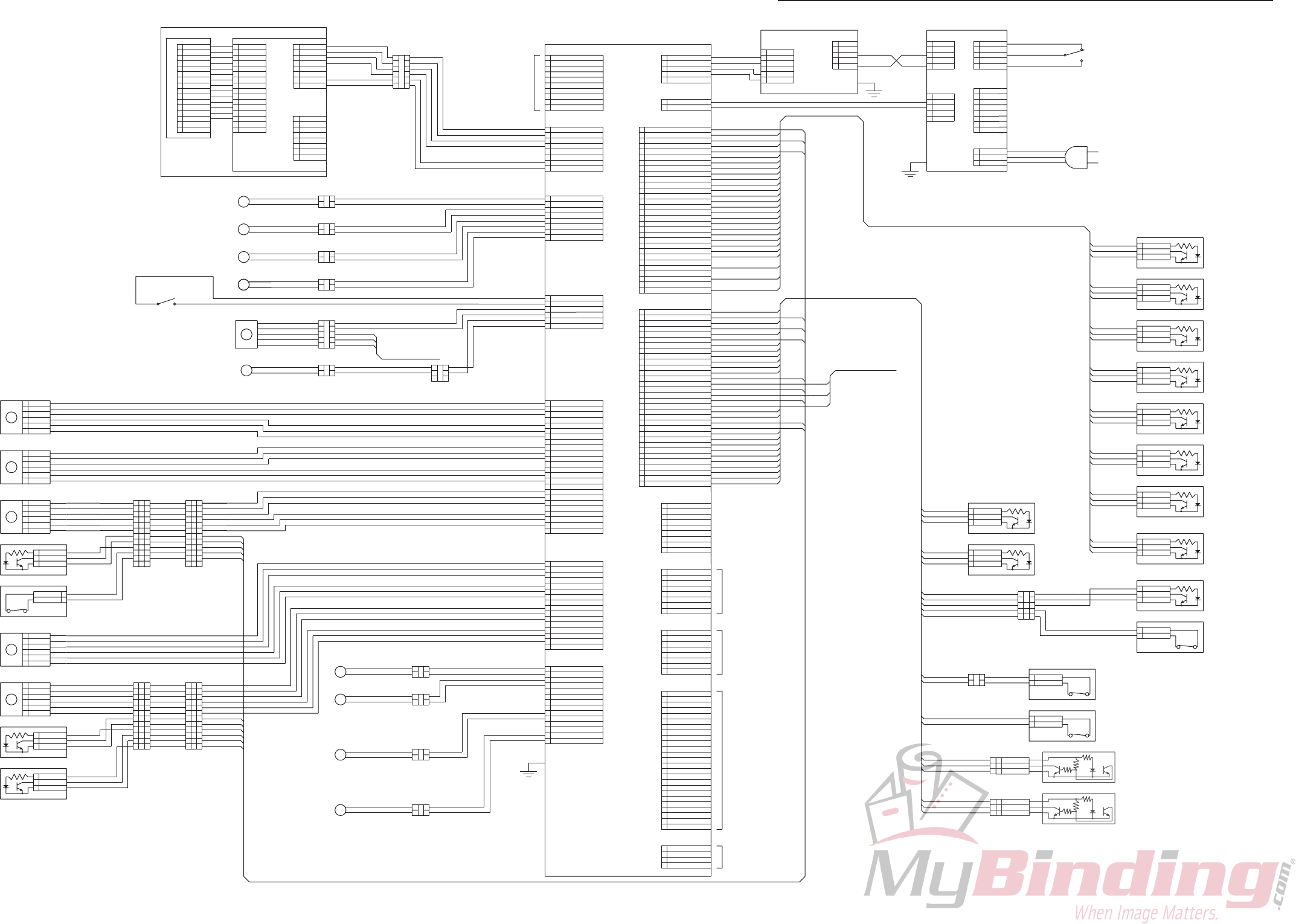
7. OVERALL SCHEMATIC DIAGRAM
Note 1) COU : Counter
Note 2) SOL : Solenoid
Note 3) SPM : Stepper Motor
Note 4) M : Motor
Note 5) CL : Clutch
11C-M12M0-0004-0
2-28
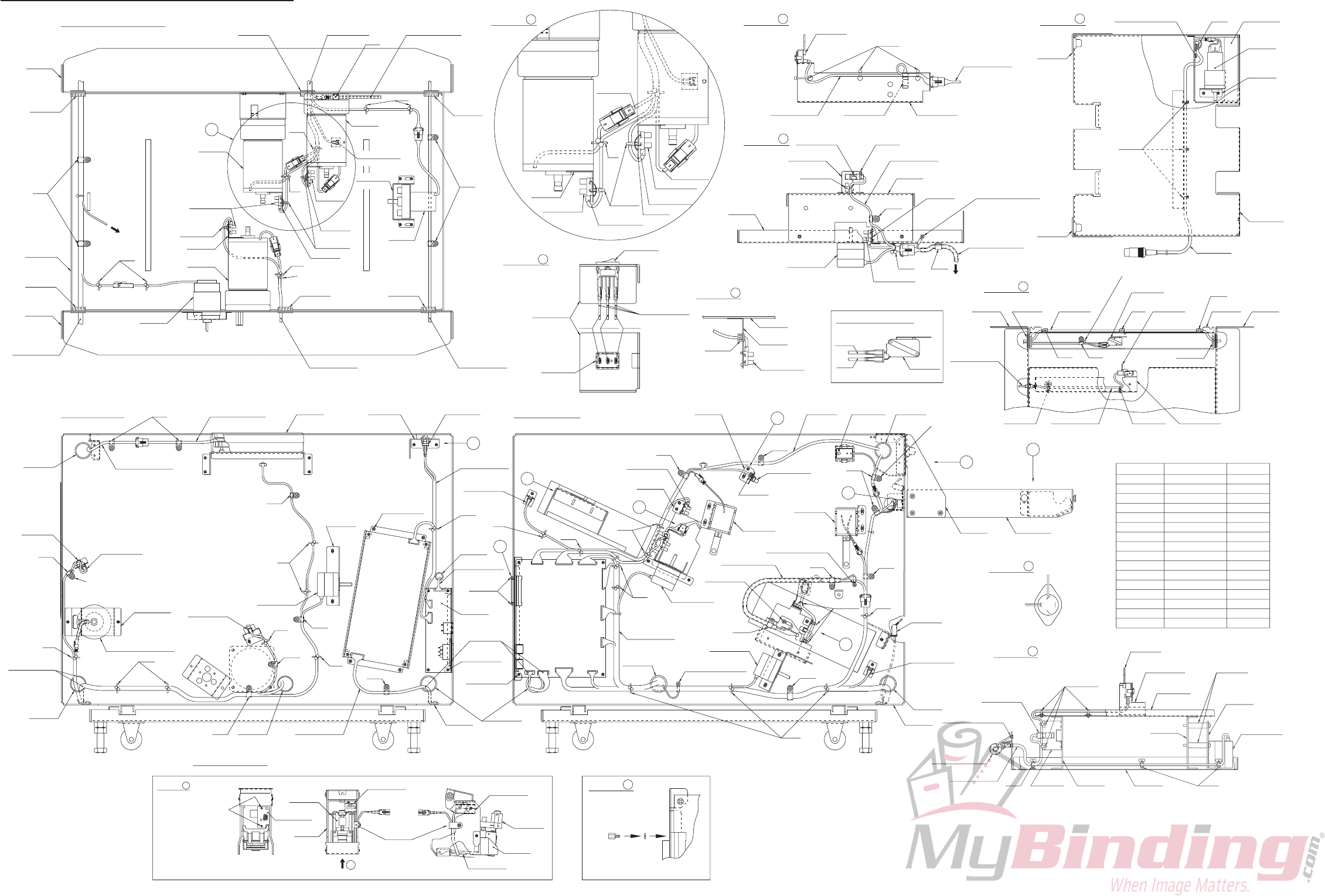
8. WIRING DIAGRAM
Brown
Bundled wire unit 2
98R-8023
Photointerrupter
Details of B
Details of F
Details of E
Details of H
Details of A
Details of J
Details of G
11C-4023
Angle B
B
H
11C-8309
OP bundled
wire unit 2
11C-8105
DC solenoid
OCB-1000
99J-8103
Counter unit
3303
Note) Adjust the clamp angle
so that the bundled wire
does not touch the bearing.
View of a
11C-3604
Details of D
E
A
D
F
OCB-1000
3303
3302
248
1197
248
248
11C-8306
Bundled wire unit 6
3302
248
5076
1197
3304 3303
3304
5076
3305
11C-8305
Bundled wire unit 5
11C-1350
Sensor bracket
11C-1304
Frame
SKB-100PR
3302
11C-3604
Bracket
Bracket
054-10246
Switch
OCB-500
OCB-1000
99A-8013
Stepping motor
11C-3644
Plate
11C-3650
Sensor base
98R-8023
Photointerrupter
98R-8023
Photointerrupter
11C-2040
PH angle
OCB-375
11C-6005
Frame B
3302
054-10246
Switch
11C-1311
PH angle
99A-8013
Stepping motor
11C-4020
Stacker table
98R-8023
Photointerrupter
Details of I
11C-4022
Angle F
11C-4020
Stacker table
11C-4023
Angle B
3303
11C-8310
ST cable unit
11C-4030
Motor bracket
3302
OCB-1000
11C-4032
Angle
11C-8104
Motor
3304
SK binder
Cable clamp
Cable clamp
3306
Cable clamp
Cable clip
Cable clip
Cable clip
Cable clip
Bushing
Cable clamp
Bushing
056-10622
248
11C-3603
Base
056-00876
99J-8015
OP unit
11C-1367
Angle
99A-8013
Stepping motor
98R-8023
Photointerrupter
11C-4515
Clutch bracket
Details of left side
054-10259
Switch
98R-8023
Photointerrupter
* Face the protruding part
inside and then tighten.
SKB-1M
11C-8031
ST P.W.B. unit
11C-8106
Electromagnetic clutch unit
11C-1629
PH angle
9 9
* Apply screwlock to the
screw tip and then tighten.
However, the screwlock
must not spill out at the
back.
NITTO SEIKO
3 types of tap-tight
(B tight) screw M2 × 3.5
11C-2001
Sensor bracket
98R-2004
Stapler unit
98R-2005
Holder
99A-8013
98R-8023
Photointerrupter
99A-8013
Stepping motor
Stepping motor
Details of stapler unit
* Lead wire should not be too
taut when the stapler unit is moved
up and down. 11C-8031
ST P.W.B. unit
OCB-375
003-80589
DC solenoid
Details of C
4253
11C-3651
Sensor bracket
C
3304
Cable clamp
98R-2004
Stapler unit
98R-2005
Holder
11C-2001
Sensor bracket
11C-6018
Cover LD
11C-6004
Frame F
a
Details of microswitch
COM
Details of bottom plate section
NC
11C-6216
Sensor bracket
98R-8023
Photointerrupter
SKB-100PR
Orange
054-10248
Microswitch
1F55
G
11C-8013
RM unit
OCB-500
Push mount ties
3305
1197
248
Type No.
5076
No.Name
4253
SKB-1M
SKB-100PR
056-10164
056-07007
056-07008
056-09004
056-09003
056-10282
056-09001
056-00003
056-10027BushingOCB-375
056-09002
Cable clip
3303
SKB-100PR
OCB-1000
SKB-100PR
248
11C-2080
PH angle
248
11C-1631
Sensor bracket
11C-8302
OCB-1000
11C-3605
PH angle
3303
SKB-100PR
1197
11C-8021
Switching power supply
056-10211
056-07006
Cable clamp3308 056-09007
054-10258
Power switch
Gray Black Purple
11C-6005
Frame B
SKB-100PR
11C-8301
Bundled wire unit 1
11C-8305
Bundled wire unit 5
SKB-1M
11C-8311
BJU bundled wire unit
98R-8023
Photointerrupter
11C-8304
Bundled wire unit 4
056-090053306 Cable clamp
Details of right side
11C-8312
STU bundled wire unit
11C-8303
Bundled wire unit 3
11C-8308
OP bundled wire unit 1
11C-8306
Bundled wire unit 6
11C-8306
Bundled wire unit 6
3305
11C-8306
Bundled wire unit 6
SKB-100PR
11C-8307
Bundled wire unit 7
11C-8305
Bundled wire unit 5
11C-8305
Bundled wire unit 5
11C-8305
Bundled wire unit 5
11C-1310
Base plate
SKB-1M
33051197
11C-8007
MC unit
11C-6323
Motor bracket
11C-6004
Frame F
11C-8103
Motor unit
OCB-1000
3303
11C-8101
Motor
11C-8101
Motor
0248
11C-2080
PH angle
98R-8023
Photointerrupter
98Y-8516
Motor
OCB-1000
98R-8023
Photointerrupter
11C-2040
PH angle
98R-8023
Photointerrupter
OCB-1000
1197
OCB-1000
054-10258
Power switch
1F55
11C-6005
Frame B
OCB-1000
11C-6004
Frame F
248
SKB-100PR
11C-2080
PH angle
98R-8023
Photointerrupter
11C-6007
Bottom plate
OCB-1000
11C-6005
Frame B
OCB-1000
11C-8102
Motor
OCB-1000
248
11C-2080
PH angle
1197
248
3303
054-10248
Microswitch
OCB-1000
11C-8309
OP bundled
wire unit 2
To switch
056-10970
Spacer
CN2
11C-6025
Switch angle
3303
3303
CN5 CN6 CN7
CN10
054-10259
Switch
3305
CN12
CN16
To bundled wire unit 5
11C-8311
BJU bundled wire unit
Yellow
Brown
CN1
11C-8312
STU bundled wire unit
CN1 CN13
CN11 CN15
Brass screw M4 with SW
Brass screw M4
with SW
054-10258
Power switch
98R-8023
Photointerrupter
3303
Brass screw M4 with SW
3302
I
11C-8309
OP bundled wire unit 2
11C-8307
Bundled wire unit 7
98R-8023
Photointerrupter
11C-8305
Bundled wire unit 5
11C-8305
Bundled wire unit 5
3305
Brass screw M3
with SW
Brass screw M3
with SW
Brass screw M4 with SW
Brass screw M4 with SW
98R-8023
Photointerrupter
11C-2080
PH angle
Purple, Pink, Blue
Brass screw M4
with SW
Yellow, Brown
Sky blue, Brown
Sky blue, Pink, Blue
3308
Brass screw M4 with SW
1
2
3
Note) Attach the power switch
and switch bracket in the
color-order and direction
shown in the figure.
11C-6025
Switch bracket
OCB-1000
SKB-100PR
Note) Attach the bundled wire unit SKB-1M
at the position shown in the figure.
Note) Adjust the clamp angle so that the bundled
wire does not touch the index disc.
J
056-10330
HD-LNA
Note) Insert a spring
washer and
secure.
Note) Attach the bundled wire unit SKB-1M
at the position shown in the figure.

11C-M12M0
