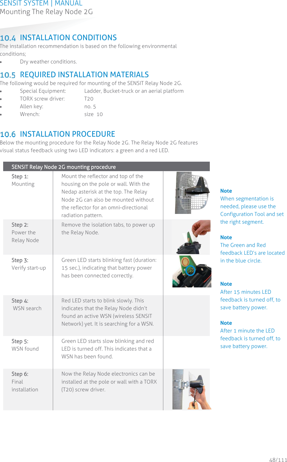
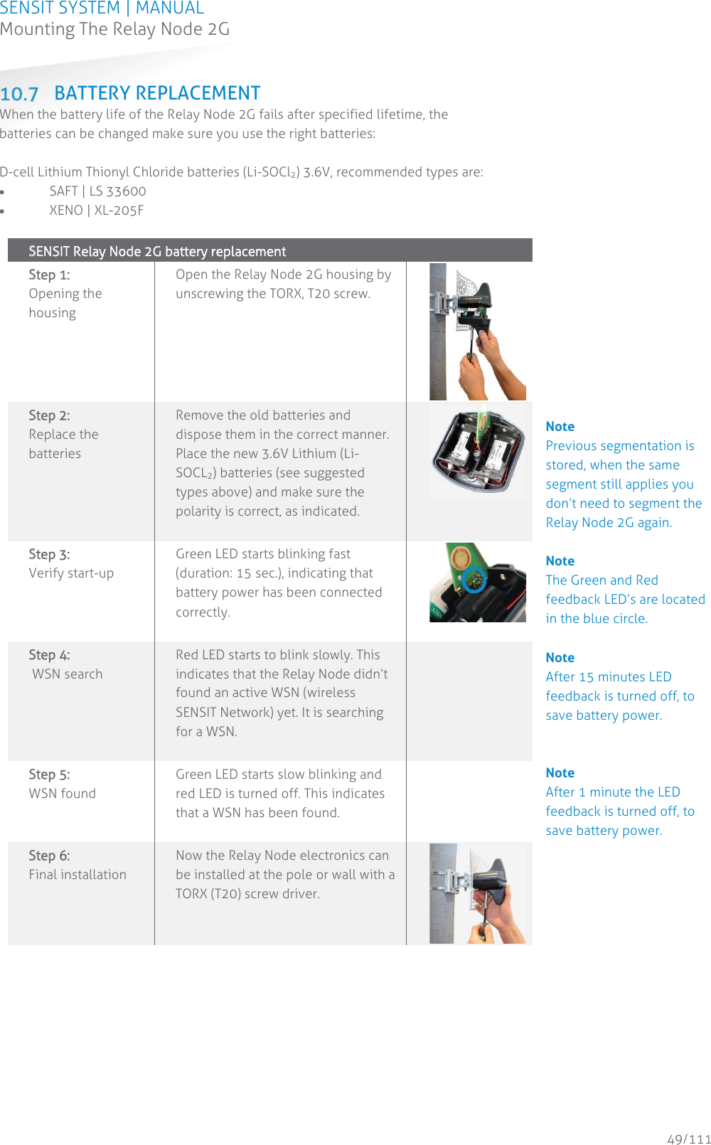
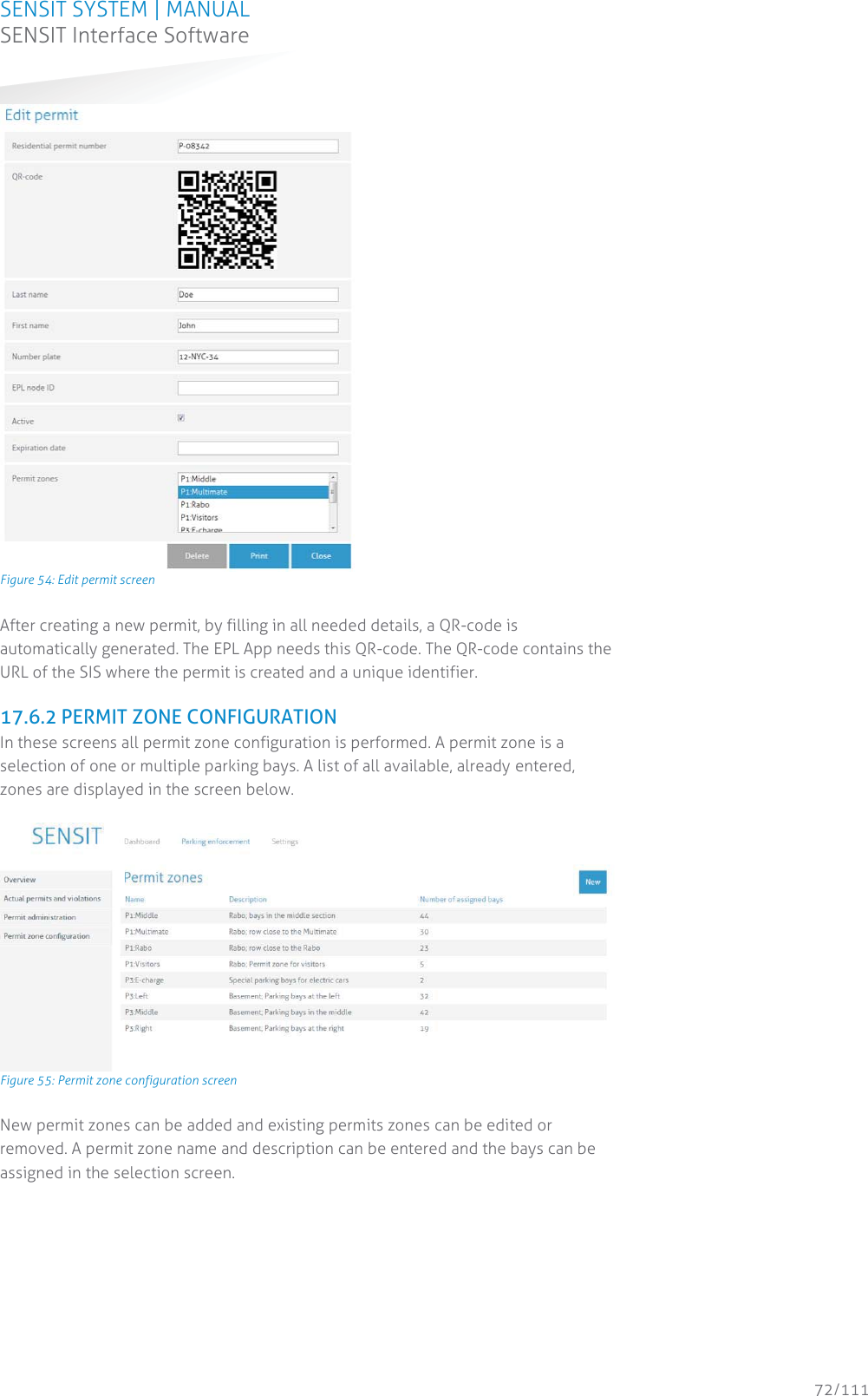
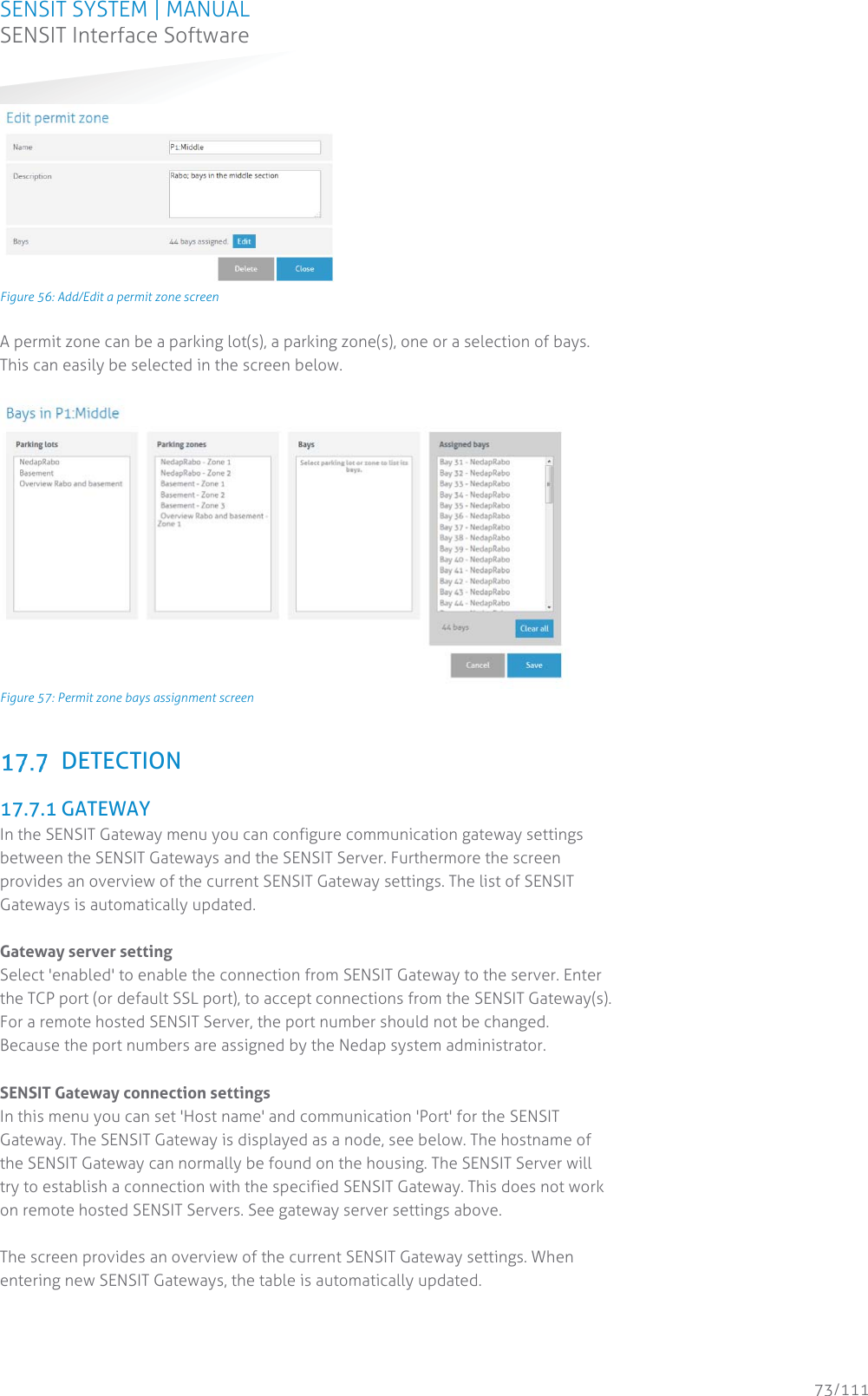
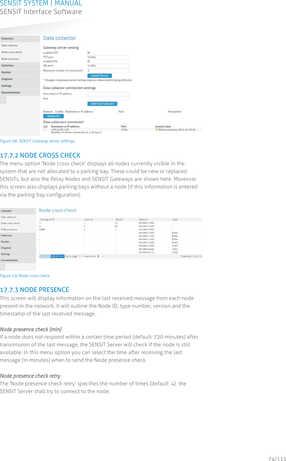
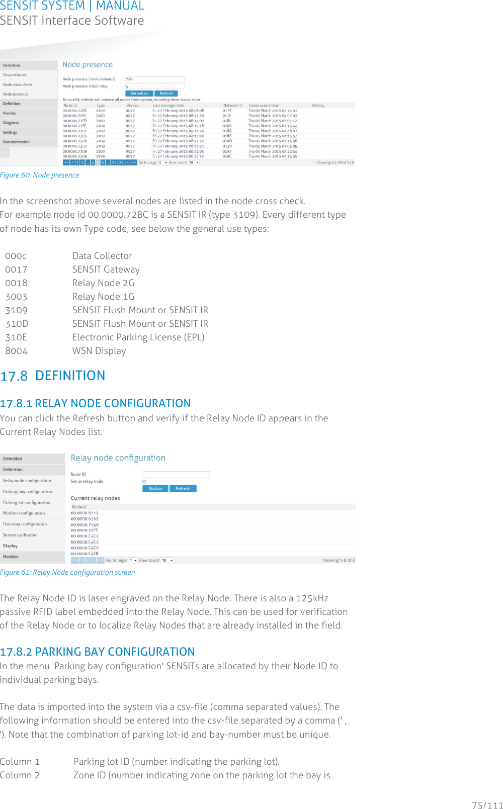
N V Nederlandsche Apparatenfabriek NEDAP SENSITGW SENSIT GATEWAY US User Manual Report
N. V. Nederlandsche Apparatenfabriek NEDAP SENSIT GATEWAY US Report
UserManual.wiki
>
N V Nederlandsche Apparatenfabriek NEDAP
>
SENSITGW User Manual
Manual
Navigation menu
Upload a User Manual
Namespaces
Wiki Guide
HTML
PDF
Info
Views
User Manual
Discussion / Help
Navigation


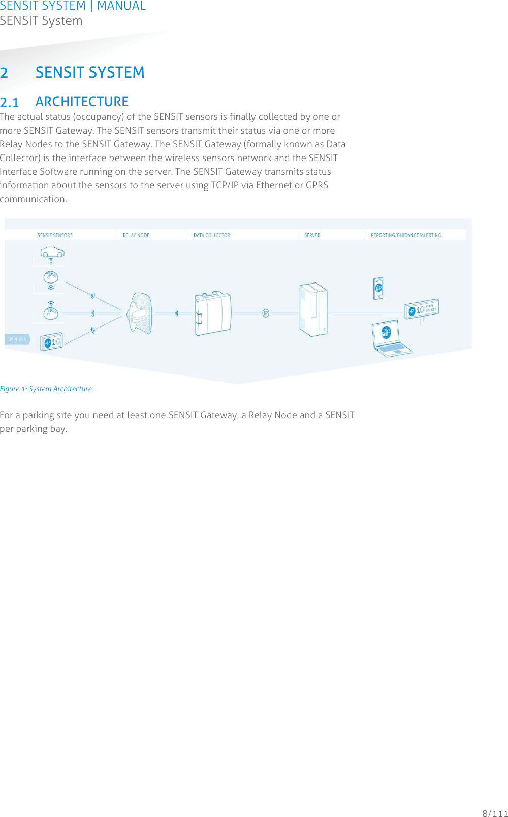
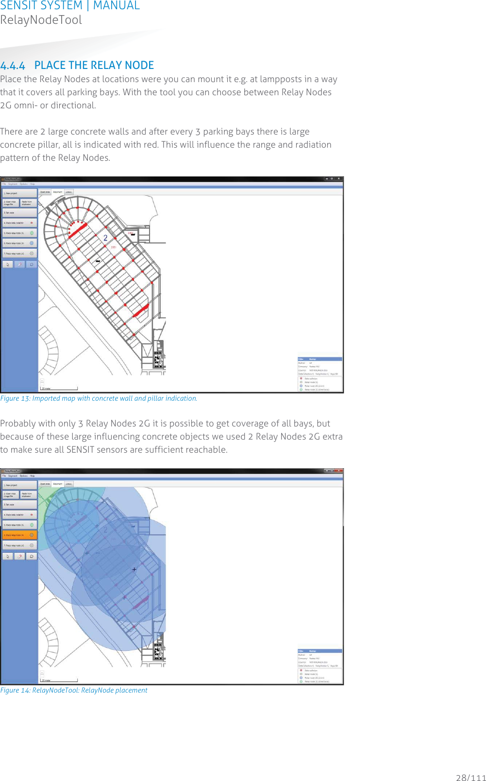
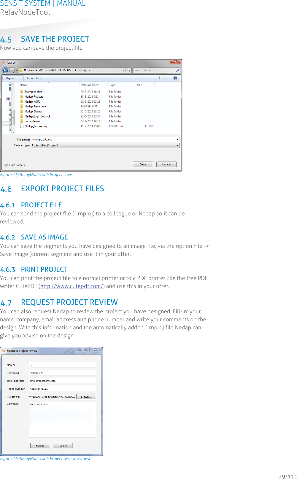
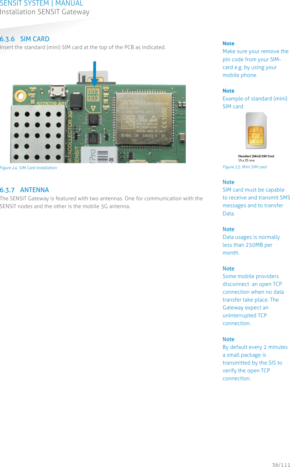
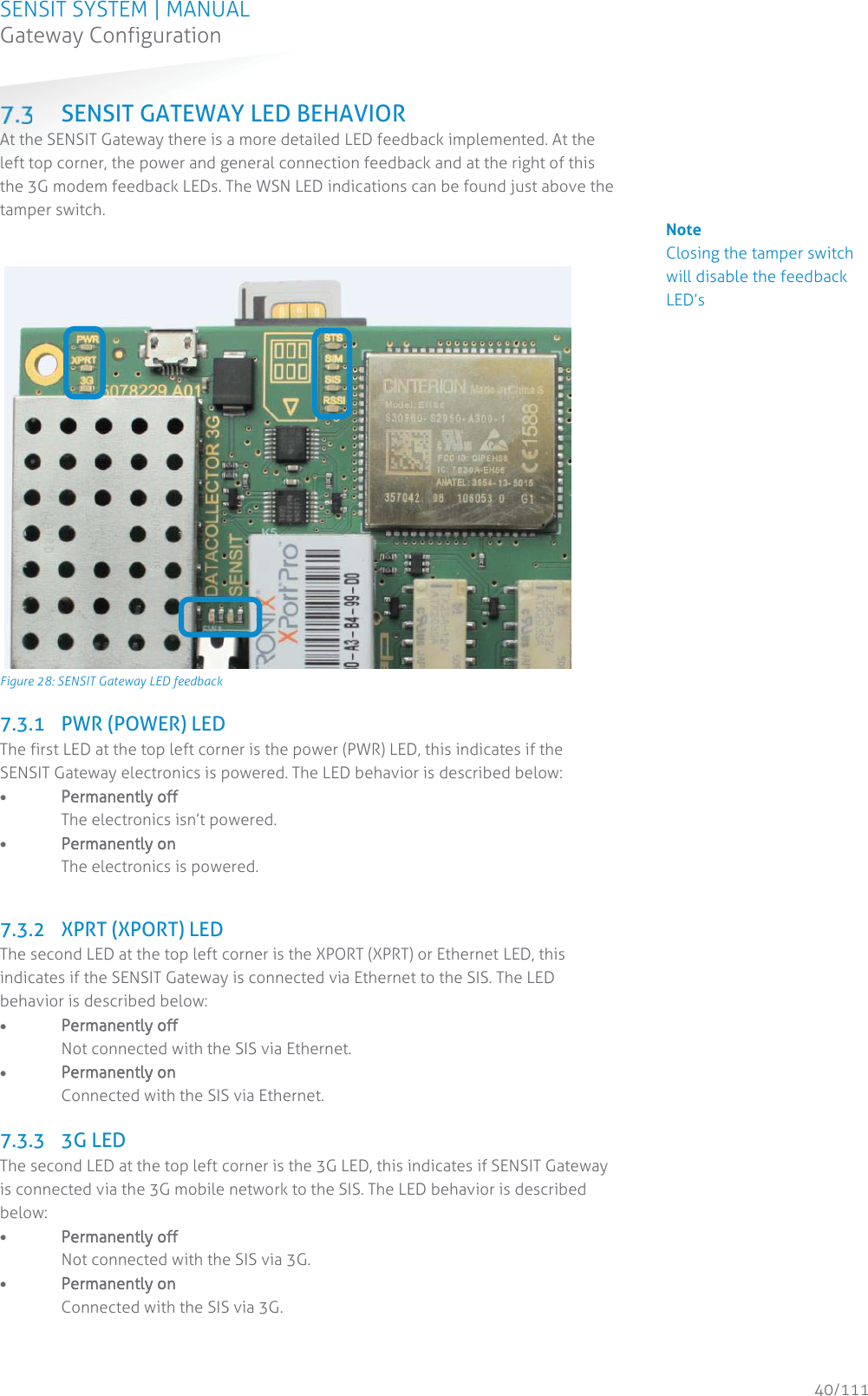
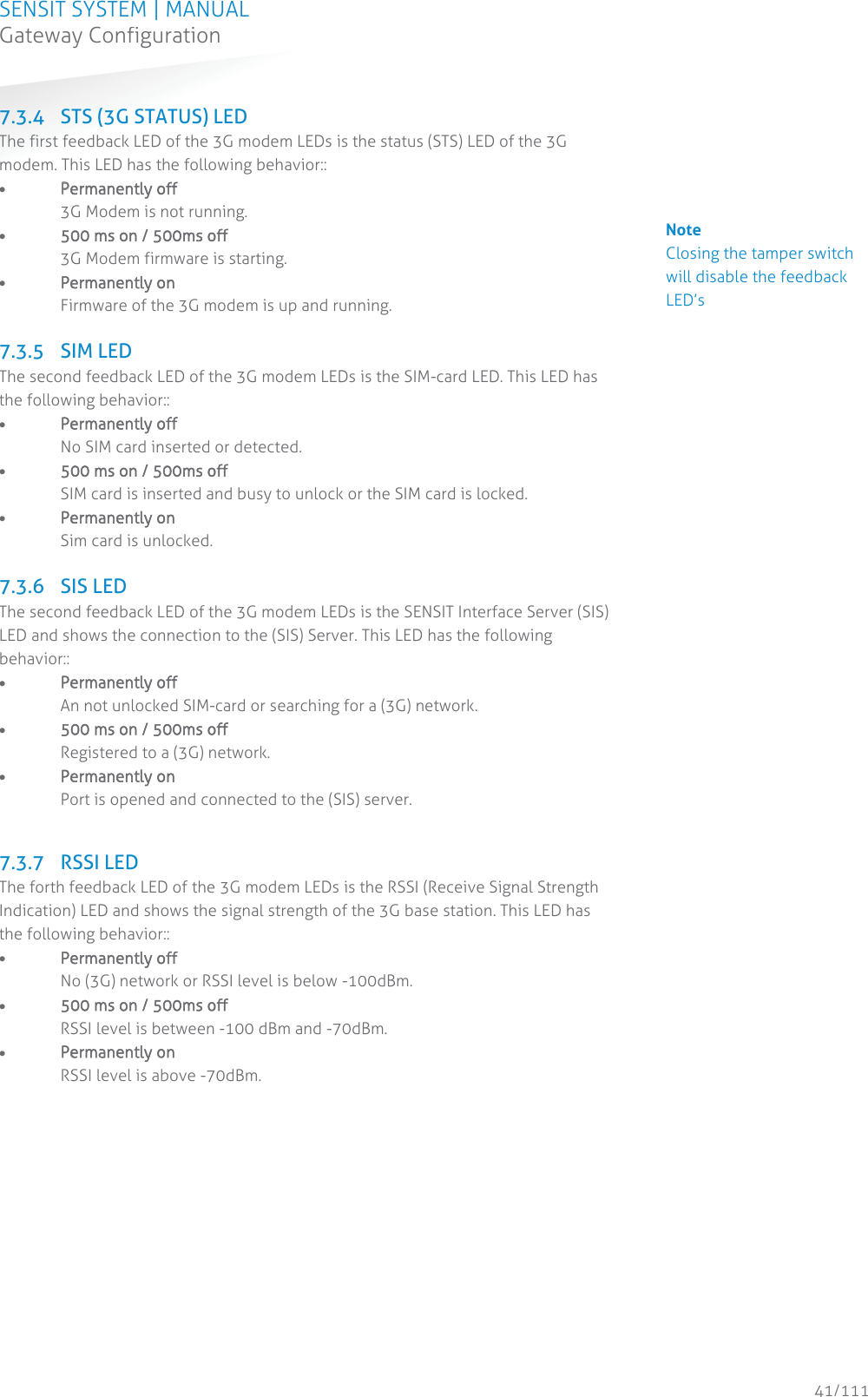
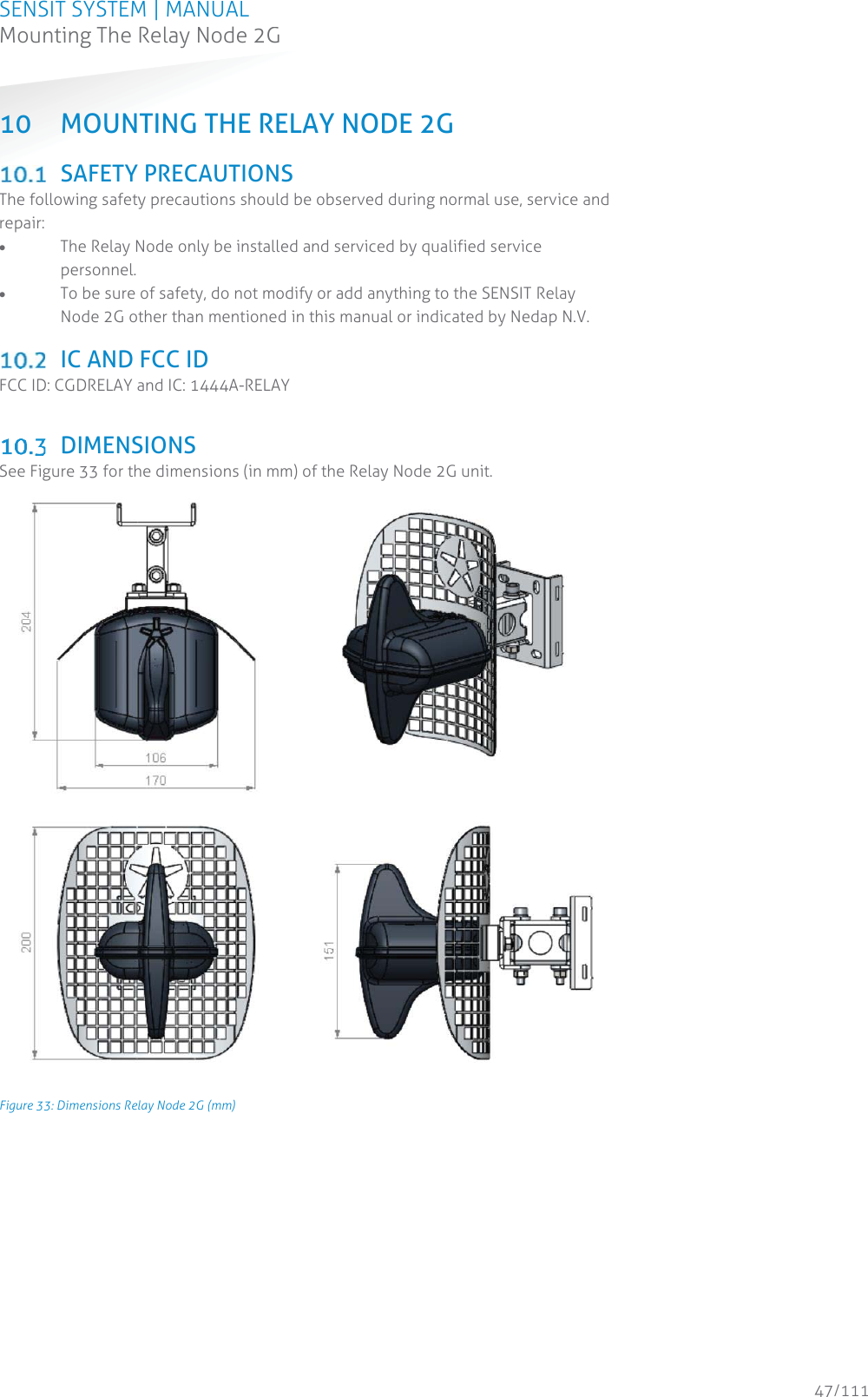
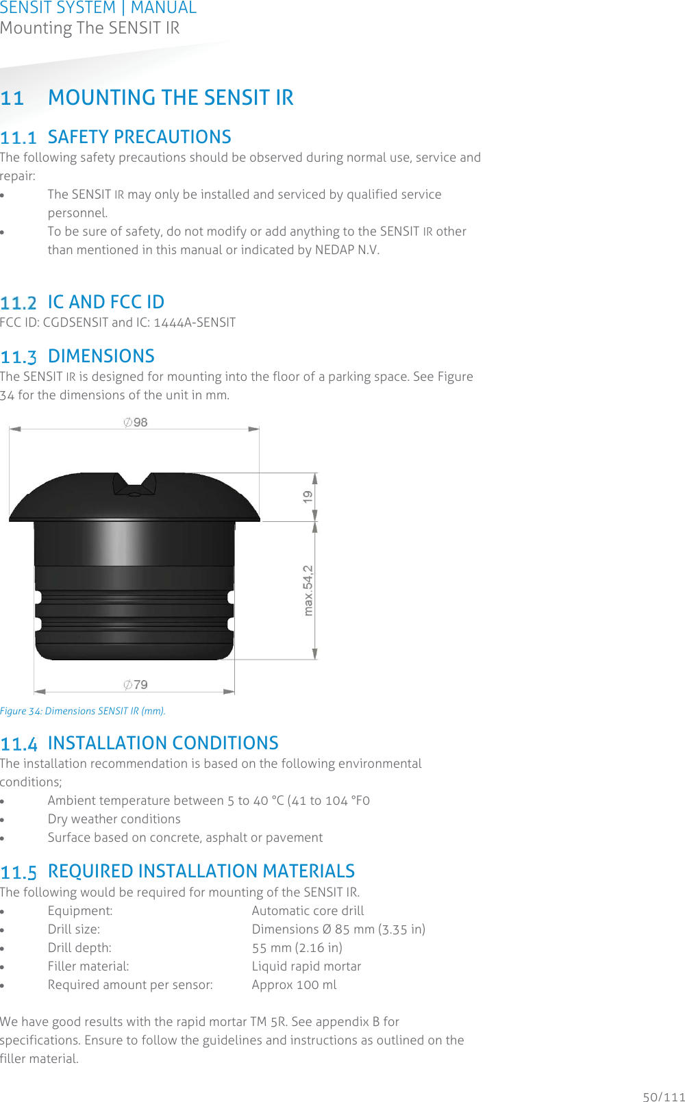
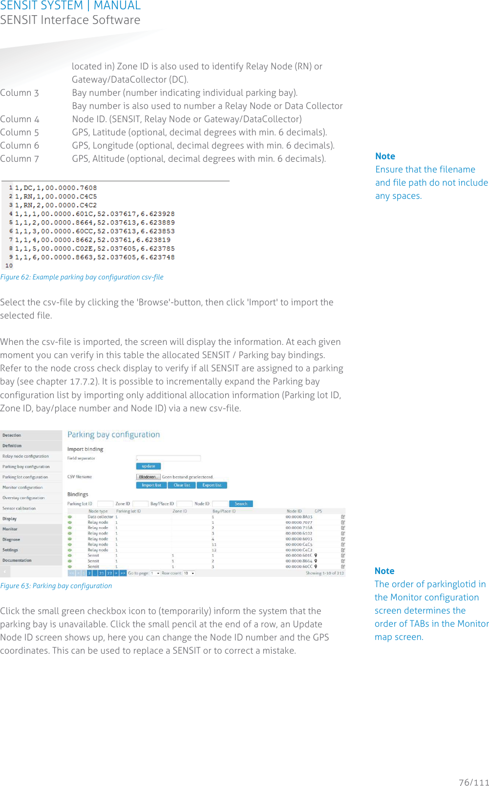
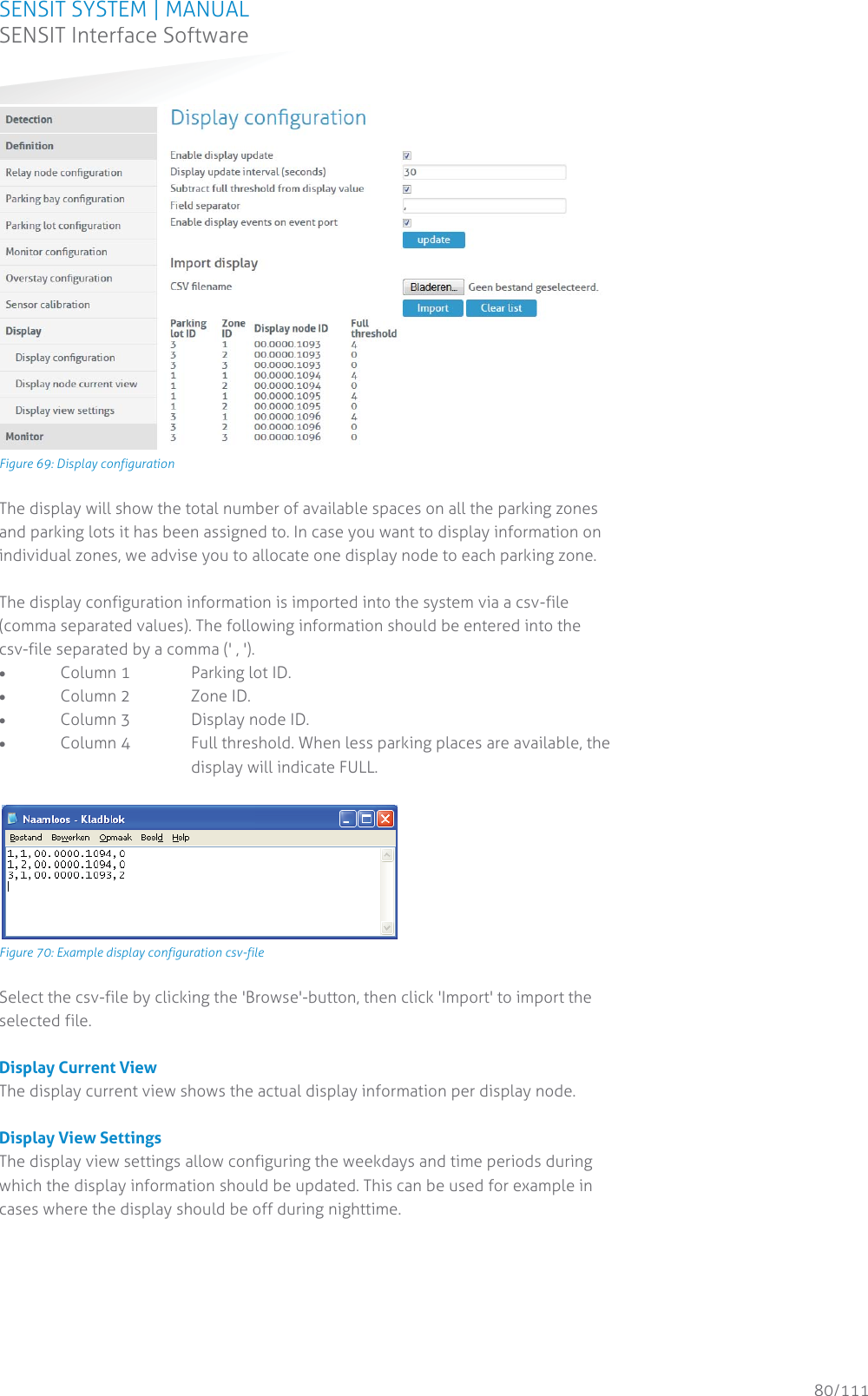
![SENSIT SYSTEM | MANUAL SENSIT System 13/111 SENSIT System RELAY NODES A Relay Node allows for communication increase and ensures a robust and reliable communication network. It ensures fast transmission of event messages from the vehicle detection sensors to the SENSIT Gateway. 2.3.1 SENSIT RELAY NODE 2G The Relay Node 2G is has an improved communication range and a battery lifetime. It ensures a robust and reliable communication network. The Relay Node 2G ensures fast transmission of event messages from the SENSIT sensors to the SENSIT Gateway. Relay Node 2G should be mounted preferable at about 3 – 6 meters [10- 20 ft] from the floor (e.g. onto a lamppost) to allow for visible view of the sensors. RRelay Node 2G Operating frequency SENSIT RELAY NODE 2G EU: 868.2 MHz SENSIT RELAY NODE 2G CN: 868.2 MHz SENSIT RELAY NODE 2G US: 902-928 MHz (FHSS) SENSIT RELAY NODE 2G AU: 915-928 MHz (FHSS) SENSIT RELAY NODE 2G NZ : 920-925MHz (FHSS) SENSIT RELAY NODE 2G SG : 920-925MHz (FHSS) SENSIT RELAY NODE 2G ID : 923-925MHz (FHSS) SENSIT RELAY NODE 2G MY : 919-923MHz (FHSS) Weight 540 gram (12.87 oz) Dimensions 200 x 170 x 204 mm (7.87 x 6.69 x 8.03 inch) Mounting Onto a pole, lamppost or wall, mounting bracket included. Mounting height 3 – 6 meters (10 – 20 ft.) Pole dimensions Min. Ø 40 mm (1.57 inch) Max. Ø 150 mm (6 inch) Protection IP65 Operating temperature -40 ... +85°C (-40°F … +185°F) Communication range * DC – RN 2G omnidirectional 35 m (135 ft) DC – RN 2G directional max. 50 m (164 ft) DC GPRS – RN 2G max. 10 m (33 ft) RN 2G – RN 2G max. 100m (328 ft) SENSIT – RN 2G omnidirectional 35 m (135 ft) SENSIT – RN 2G directional 50 m (164 ft) Power supply ** Replaceable Lithium batteries expected lifetime of 5 years Antenna connection Antenna included * Dependent on the environment. ** Under normal circumstances and dependent on settings.](https://usermanual.wiki/N-V-Nederlandsche-Apparatenfabriek-NEDAP/SENSITGW/User-Guide-3466938-Page-13.png)
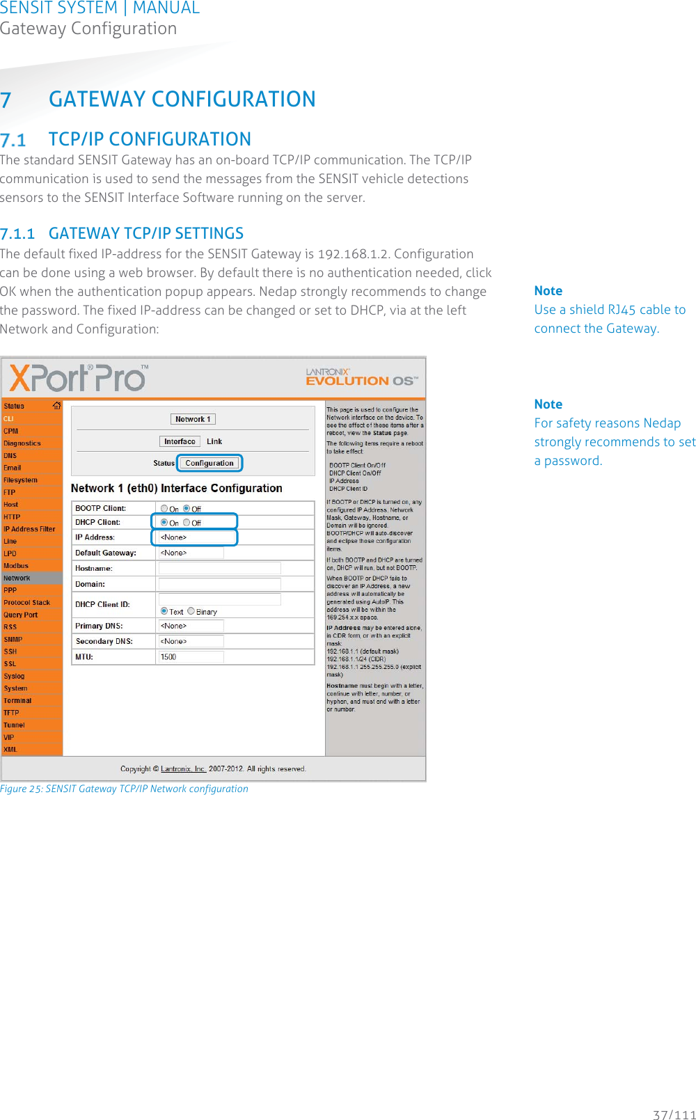
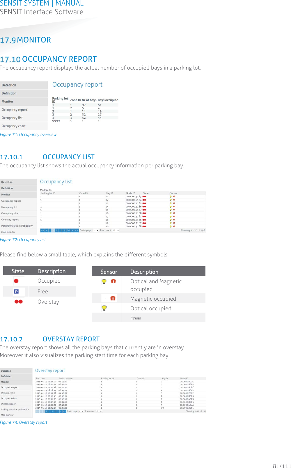
![SENSIT SYSTEM | MANUAL SENSIT System 17/111 SENSIT System2.5.2 SENSIT DISPLAY The SENSIT Display enables signage of available parking spaces for stand-alone parking guidance installations. The display is designed for outdoor use, indicating the number of available parking spaces per parking lot thus guiding motorists to the closest parking space. Availability of parking spaces can be indicated per zone, for the specific zone the SENSIT Display is allocated to. Configuration of the display can be realized using the SENSIT Interface Software. SSENSIT Display Display Graphical display for outdoor use, single sided Dimensions 330 x 221 x 171 mm (13.0 x 8.7 x 6.7 inch) Display dimensions 320 x 160 x 15 mm (12.6 x 6.3 x 0.6 inch) Weight 5900 gram (208 oz) Protection IP65, UV protected Color Stainless steel housing, Amber LEDs Character height 160 x 100 mm [h x w] (6.3 x 3.9 in) Number of digits 3 Readability 5.000 cd/m2, readable in full sunlight. Luminance Ambient light luminance regulation. Viewing angle 70º/35º Operating temperature -20 ... +60°C (32°F … +122°F) Power supply 110-230 VAC 50/60Hz or PoE+ (25W) Relay outputs 3 Low voltage relays](https://usermanual.wiki/N-V-Nederlandsche-Apparatenfabriek-NEDAP/SENSITGW/User-Guide-3466938-Page-17.png)
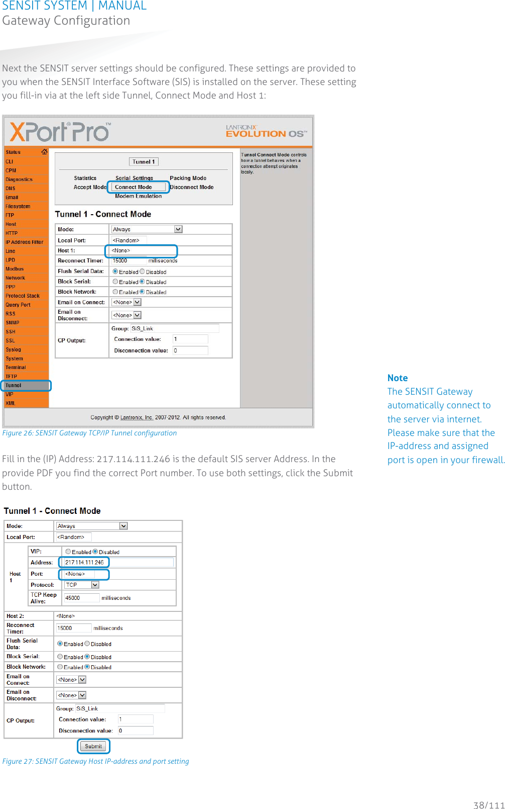
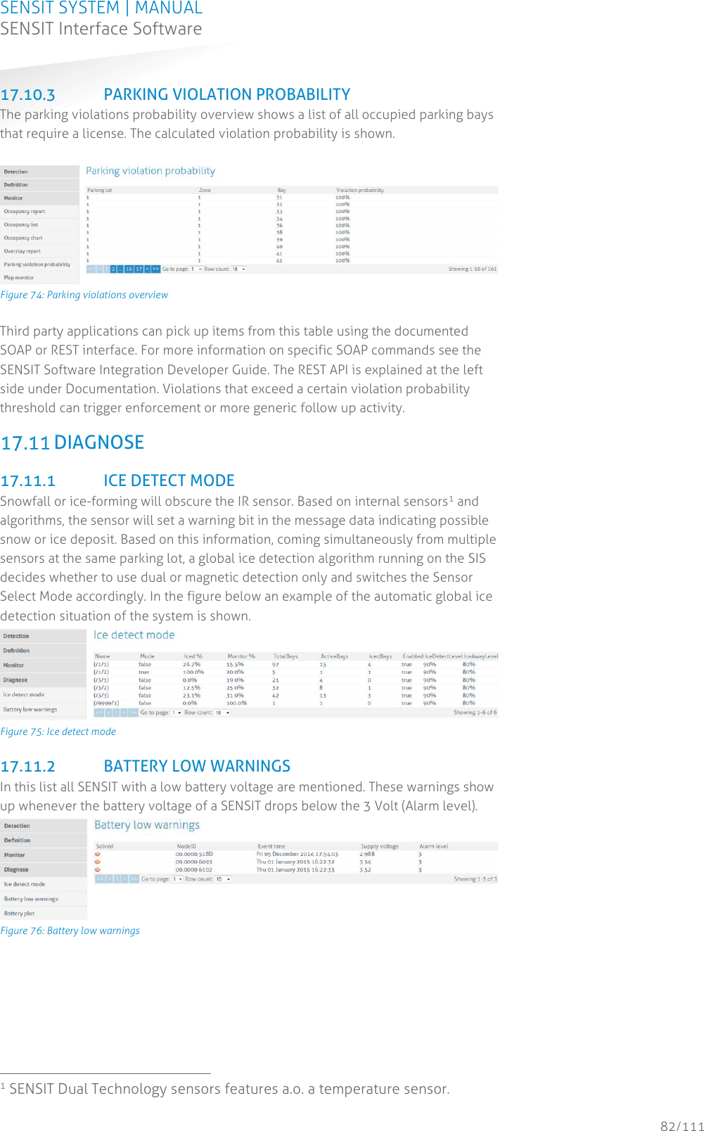
![SENSIT SYSTEM | MANUAL Mounting The SENSIT IR 51/111 Mounting The SENSIT IR INSTALLATION PROCEDURE Below the mounting procedure for the SENSIT sensor with and without the Configuration Tool. 11.6.1 WITHOUT THE CONFIGURATION TOOL SSENSIT sensor mounting procedure SStep 1: Preparation Indicate on the closed parking lot where the SENSIT sensor should be mounted. Distribute the SENSIT sensors over the parking lot and write down the correct ID numbers on your installation plan. Step 2: Drilling Drill a hole of Ø 85 mm [3.35 in] and at least 55 mm [2.16 in] deep into the center of the parking bay SStep 3: Gluing Apply the right amount of filler and pour into the hole. SStep 4: Mounting Double-check the node ID number and the parking bay on the installation plan and place the SENSIT sensor into the hole. SStep 5: Cleaning-up After mounting the SENSIT sensors in all parking bays or a selection of parking bays. Clean up the parking bays and remove all (metal) tools and objects. SStep 6: Activating All SENSIT sensors are set into transport/stock mode during shipment. After installation all mounted SENSIT sensors must be swept with the reset magnet. SStep 7: Calibrating After installation the SENSIT sensor must be calibrated. Ensure that the parking space is empty and that there is no car parked on top of the sensor or on neighboring parking bays. SENSIT sensors can be calibrated via the SENIST Interface Software (SIS). See chapter 17.8.6 for more information about calibration. SStep 8: Glue curing Leave the filler harden for 8 hours before vehicles are allowed in the parking space again. Note Take attention that you fixate the SENSIT sensor during the curing time otherwise the sensor will start to float. Note Once out of the transport/stock mode the battery lifetime starts to count. Note When the SENSIT sensors are not calibrated they hardly send any messages. This is due to the fact that there are no events generated because the magnetic thresholds are not crossed.](https://usermanual.wiki/N-V-Nederlandsche-Apparatenfabriek-NEDAP/SENSITGW/User-Guide-3466938-Page-51.png)
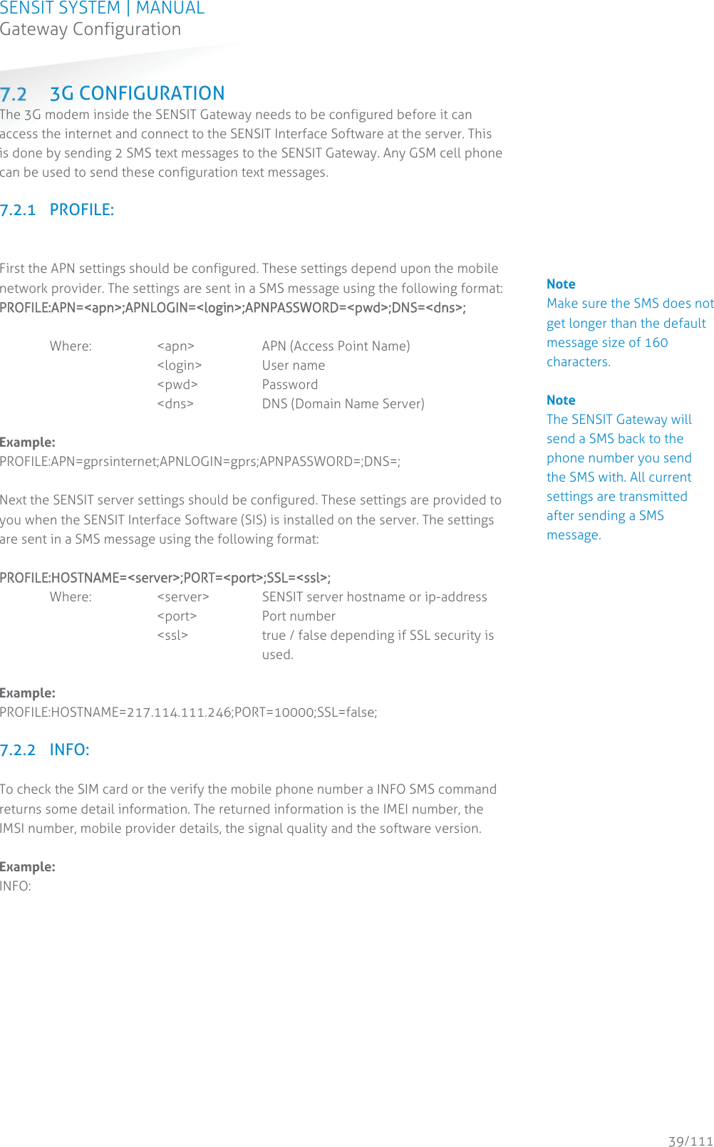
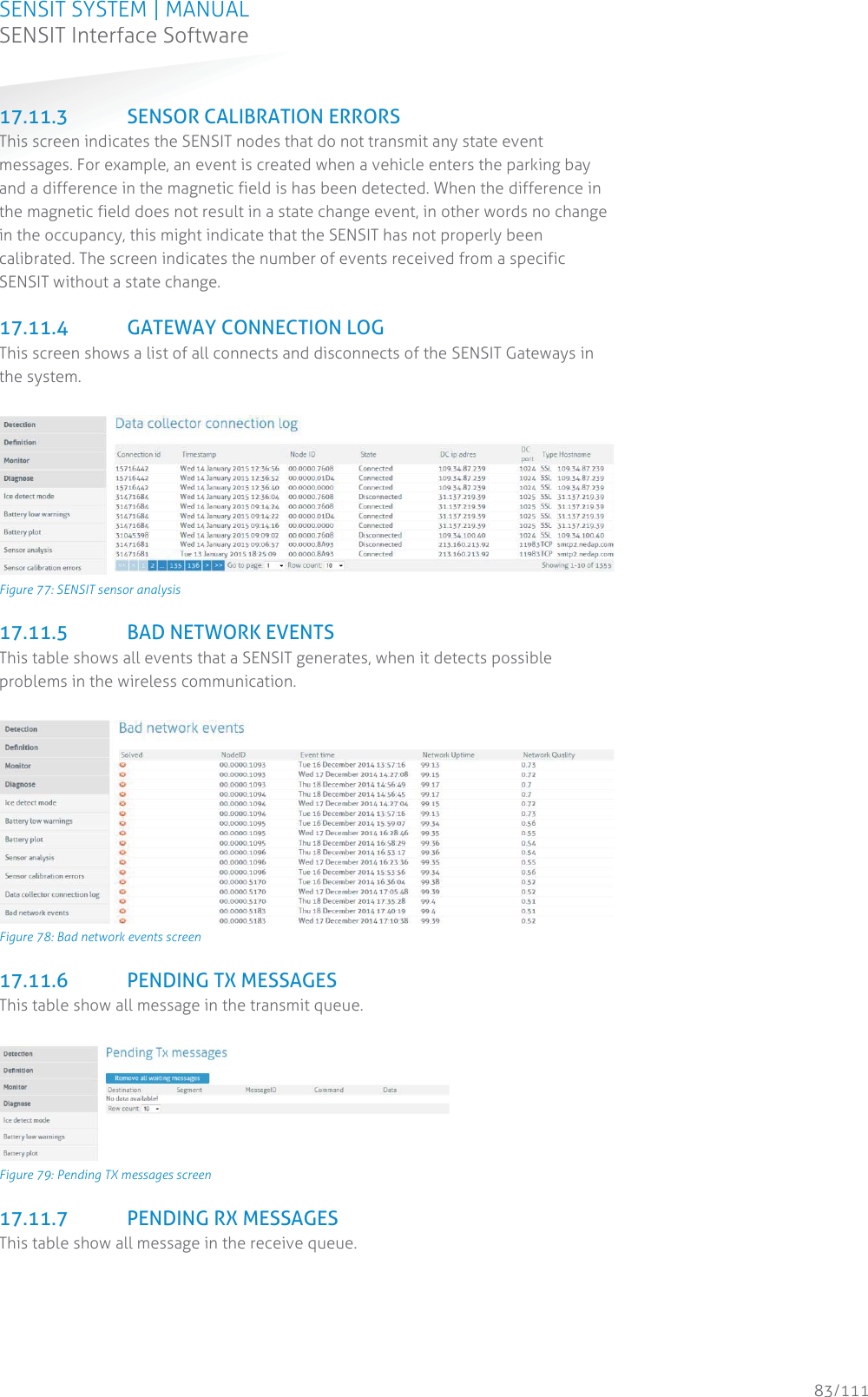
![SENSIT SYSTEM | MANUAL Mounting The SENSIT IR 52/111 Mounting The SENSIT IR11.6.2 WITH THE CONFIGURATION TOOL SSENSIT sensor mounting procedure SStep 1: Preparation Indicate on the closed parking lot where the SENSIT sensor should be mounted. Distribute the SENSIT sensors over the parking according the installation plan. Step 2: Drilling Drill a hole of Ø 85 mm [3.35 in] and at least 55 mm [2.16 in] deep into the center of the parking bay SStep 3: Gluing Apply the right amount of filler and pour into the hole. SStep 4: Mounting Place the SENSIT sensor into the hole and make sure it doesn’t start to float. SStep 5: Cleaning-up After mounting the SENSIT sensors in all parking bays or a selection of parking bays. Clean up the parking bays and remove all (metal) tools and objects. SStep 6: Activating Segmentation Calibration Use the Configuration Tool: Activate, perform the segmentation according the installation plan and calibrate the SENSIT sensor. SStep 77:: Glue curing Leave the filler harden for 8 hours before vehicles are allowed in the parking space again. REPLACEMENT When the battery life of the SENSIT IR fails after specified lifetime, we advise to replace the unit completely. The SENSIT IR is fully sealed and for outdoor use, therefore batteries cannot be replaced. Drill out the old SENSIT IR and complete the mounting procedure as describe in the previous paragraph. Ensure to note the node ID number of the SENSIT IR to the parking bay. Update the parking bay configuration list in the SIS software to ensure the new sensor is linked to the right parking bay. Note Take attention that you fixate the SENSIT sensor during the curing time otherwise the sensor will start to float. Note Once out of the transport/stock mode the battery lifetime starts to count.](https://usermanual.wiki/N-V-Nederlandsche-Apparatenfabriek-NEDAP/SENSITGW/User-Guide-3466938-Page-52.png)
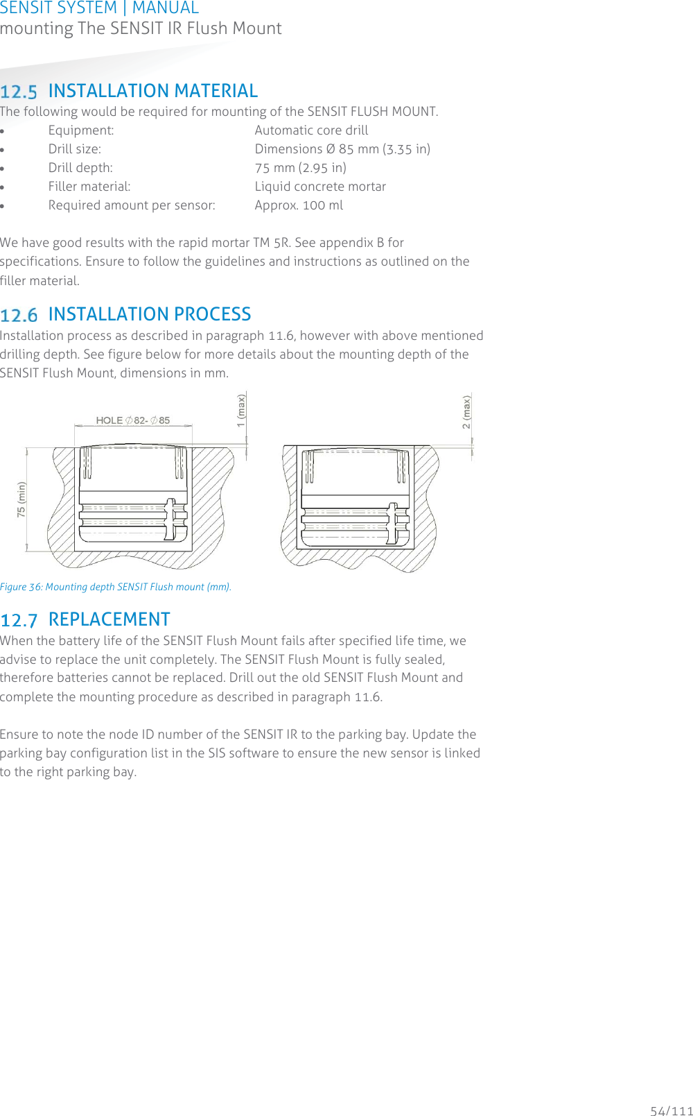
![SENSIT SYSTEM | MANUAL mounting The SENSIT IR Flush Mount 53/111 mounting The SENSIT IR Flush Mount12 MOUNTING THE SENSIT IR FLUSH MOUNT SAFETY PRECAUTIONS The following safety precautions should be observed during normal use, service and repair. x The SENSIT Surface Mount may only be installed and serviced by qualified service personnel. x To be sure of safety, do not modify or add anything to the SENSIT Surface Mount other than mentioned in this manual or indicated by NEDAP N.V. IC AND FCC ID FCC ID: CGDSENSIT and IC: 1444A-SENSIT DIMENSIONS The SENSIT Flush Mount is designed for full mounting into the floor of a parking space. As the unit is fully flush with the road surface the unit is snow plough resistant. The SENSIT Flush Mount is only featured with magnetic detection. See Figure 35 for the dimensions of the unit in mm. The top of the SENSIT Flush Mount is laser engraved with the node ID number. Figure 35: Dimensions SENSIT Flush mount (mm). INSTALLATION CONDITIONS The installation recommendation is based on the following environmental conditions; x Ambient temperature between 5 to 40 °C [41 to 104 °F] x Dry weather conditions x Surface based on concrete, asphalt or pavement](https://usermanual.wiki/N-V-Nederlandsche-Apparatenfabriek-NEDAP/SENSITGW/User-Guide-3466938-Page-53.png)


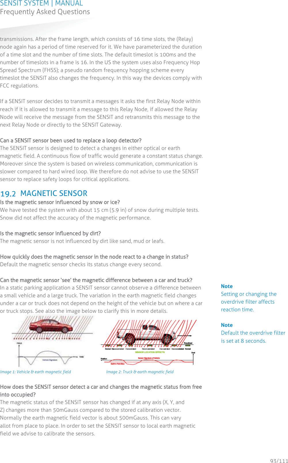
![SENSIT SYSTEM | MANUAL Frequently Asked Questions 92/111 Frequently Asked Questions19 FREQUENTLY ASKED QUESTIONS GENERAL WWhat types of SENSIT sensors are available and what is the difference? There are 3 different types of SENSIT sensors available: 1 SENSIT IR - Magnetic and optical sensor suitable to be built-into the floor of each parking space. 2 SENSIT Flush Mount - Magnetic sensor suitable to be built-into the floor of each parking space. 3 SENSIT Surface Mount - Magnetic and optical sensor for mounting onto the floor of a parking space What is the accuracy of the SENSIT Flush Mount? The magnetic sensor can achieve an accuracy of 95%. What is the accuracy of the SENSIT IR and SENSIT Surface Mount? The combination of the magnetic and optical sensor has an average accuracy of above 98%. How scalable is the SENSIT system? The SENSIT system is quite scalable. The theoretical maximum number of SENSIT nodes in one network is about 65000. In general, large installation need to be divided into smaller sub-networks (segments), which makes it better manageable and easier to understand. Sites that have more than 500 sensors or more than 15 Relay Nodes need segmentation. Please contact your Nedap account manager. What is the temperature range for the SENSIT and SENSIT IR? The temperature range for both SENSIT as well SENSIT IR is -40°C to 85°C [-40 to 185°F]. Temperatures below -30°C [-22°F] might affect accuracy of the magnetic sensor. The accuracy on the optical sensor remains unchanged. How does the dual sensor technology principle work ? The optical sensor is based on IR reflection, using a modulated high power IR LED transmitter and a sensitive IR diode as receiver. The IR radiation is reflected by the bottom of a vehicle and captured by the IR diode. The 3D magnetometer senses the variation in the earth magnetic field when a vehicle stops above the sensor. The magnetic status of the SENSIT sensor switches to “occupied” if at least one axis (X, Y or Z) measures a deviation of more than 50mGauss compared to the stored calibration vector. The IR sensor is potentially more accurate but sensitive to dirt, snow and ice. The triple axis magnetometer however is not influenced by dirt, snow or ice. By default, the sensor checks its IR sensor and magnetometer status every second. Both technologies work together to provide reliable and accurate vehicle detection. There are different modes of operation impacting how the status is calculated. For each individual sensor, the system tracks the actual status of the IR and magnetic sensor. Based on this information, the “calculated state” of the sensor (i.e. “free” or “occupied”) is determined. How does the energy efficient Wireless SENSIT Network work? The medium access protocol is based upon time division multiple access (TDMA). Time is divided into time slots, which (Relay) nodes can use to transfer data without having to content for the medium or having to deal with energy wasting collisions of](https://usermanual.wiki/N-V-Nederlandsche-Apparatenfabriek-NEDAP/SENSITGW/User-Guide-3466938-Page-92.png)
![SENSIT SYSTEM | MANUAL Frequently Asked Questions 96/111 Frequently Asked Questionsrapid mortar (eg.TM 5R). Ensure to fixate the SENSIT sensors during curing time, to avoid them from floating in the mortar. When you want to use another brand of rapid mortal please sent us the datasheet so we can analyze this and advise you on use. IIs a SENSIT IR snow plough resistant? When using the SENSIT IR in environments with snowy weather conditions, we advise to set a tolerance on the snow plough of 2 cm [0.78 in] to ensure the top of the sensor is not damaged by the snow plough. The SENSIT IR is not fully snow plough resistant; however it can withstand a few incidental hits. The SENSIT Flush Mount is snow plough resistant and can be used in areas with frequent snow conditions, at the cost of a bit lower accuracy.](https://usermanual.wiki/N-V-Nederlandsche-Apparatenfabriek-NEDAP/SENSITGW/User-Guide-3466938-Page-96.png)
![SENSIT SYSTEM | MANUAL Frequently Asked Questions 100/111 Frequently Asked QuestionsWWhere do I mount the SENSIT Gateway? The SENSIT Gateway can be installed within 25 m [84 ft] from the first SENSIT node or Relay Node. Be sure not to position the SENSIT Gateway in a metal enclosure as it will block the RF communication. The SENSIT Gateway can be mounted in a plastic housing, which is transparent for RF signals. What power wiring (cable specs) do I need for the standard Data Collector? Power: 100-240 VAC, 50-60 Hz, 180mA, Power input: 5 VDC, max 1A Power consumption: 5VA Communication between Data Collector and SIS: Ethernet Cat 5 E Can the Data Collector GPRS be powered by a solar panel? There are already several customers who autonomously power the Data Collector GPRS with a solar panel. Also the Data Collector GPRS at the Nedap test-site is powered by a solar panel (since December 2011). The autonomous solar panel system at the Nedap test-site is a 30Wp Solar panel, a charge regulator and two 22Ah /12V battery in parallel. See picture at the right The Data Collector will not consume more than 60mA at 12VDC on average. Can the SENSIT Gateway be powered by a solar panel? The SENSIT Gateway can also be powered by a Solar panel and it will not consume more than 120mA at 12VDC on average. How much data will a the SENSIT Gateway use? Normally the data usage will be below 250MB per month. Can I replace the antenna for one that I can mount on top of a metal box and keep the SENSIT Gateway inside this metal cabinet? As for operational purposes this should not be an issue, on the condition that a suitable antenna is applied. However ETSI and FCC does not allow change of the antenna, and therefore as a manufacturer we cannot approve antenna change for this reason. How often does the SENSIT sensor send an event to the SENSIT Gateway to alert a status change? The SENSIT sensor sends an event message immediately after a status change. The baud-rate of the Data Collector is 115200 can I change it into another value? The baud-rate of the Data Collector is fixed, you cannot change it. Can I built the SENSIT Gateway into a pay & display machine? Yes, when the pay & display machine is featured with Ethernet communication, this communication could be applied. Keep into consideration that the RF antenna of the Gateway should be positioned behind RF transparent material (such as plastic) and not incorporated in metal.](https://usermanual.wiki/N-V-Nederlandsche-Apparatenfabriek-NEDAP/SENSITGW/User-Guide-3466938-Page-100.png)