N V Nederlandsche Apparatenfabriek NEDAP SENSITGW SENSIT GATEWAY US User Manual Report
N. V. Nederlandsche Apparatenfabriek NEDAP SENSIT GATEWAY US Report
Manual

SENSIT SYSTEM
install guide
06
-07-2017 | v1.6 RC6

SENSIT SYSTEM | MANUAL
Introduction
2/
111
In
tr
od
uc
ti
on
CONTENT
1 INTRODUCTION _______________________________________________________ 7
2 SENSIT SYSTEM________________________________________________________ 8
ARCHITECTURE _________________________________________________ 8
THE SENSIT SENSORS ____________________________________________ 9
2.2.1 SENSIT IR FLUSH MOUNT ___________________________________ 9
2.2.2 SENSIT IR _______________________________________________ 10
2.2.3 SENSIT FLUSH MOUNT ____________________________________ 11
2.2.4 SENSIT SURFACE MOUNT __________________________________ 12
RELAY NODES _________________________________________________ 13
2.3.1 SENSIT RELAY NODE 2G ___________________________________ 13
SENSIT GATEWAY ______________________________________________ 14
2.4.1 THE GATEWAY ___________________________________________ 14
2.4.2 GATEWAY COMMUNICATION BACKUP _______________________ 14
2.4.3 SENSIT BACKUP BATTERY __________________________________ 15
ADDITIONAL EQUIPMENT ________________________________________ 16
2.5.1 ELECTRONIC PARKING LICENSE ____________________________ 16
2.5.2 SENSIT DISPLAY __________________________________________ 17
2.5.3 SENSIT CONFIGURATION TOOL _____________________________ 18
SENSIT INTERFACE SOFTWARE ___________________________________ 19
3 INSTALLATION PROCEDURES ___________________________________________ 20
4-STEPS WITHOUT THE CONFIGURATION TOOL _____________________ 20
3.1.1 STEP 1 – PREPARATION ___________________________________ 20
3.1.2 STEP 2 – GATEWAY AND RELAY NODE INSTALLATION __________ 20
3.1.3 STEP 3 – SENSIT INSTALLATION _____________________________ 20
3.1.4 STEP 4 – SETTING UP THE SENSIT INTERFACE SOFTWARE _______ 20
4-STEPS WITH THE CONFIGURATION TOOL _________________________ 21
3.2.1 STEP 1 – PREPARATION ___________________________________ 21
3.2.2 STEP 2 – GATEWAYS AND RELAY NODE INSTALLATION _________ 21
3.2.3 STEP 3 – SENSIT INSTALLATION _____________________________ 21
3.2.4 STEP 4 – SETTING UP THE SENSIT INTERFACE SOFTWARE _______ 21
4 RELAYNODETOOL ____________________________________________________ 22
SCALED DRAWING ______________________________________________ 22
START A NEW PROJECT __________________________________________ 23
THE FIRST SEGMENT ____________________________________________ 23
4.3.1 IMPORT MAP ____________________________________________ 24
4.3.2 SET THE SCALE___________________________________________ 24
4.3.3 PLACE THE GATEWAY _____________________________________ 25
4.3.4 PLACE THE RELAY NODE __________________________________ 25
THE SECOND SEGMENT _________________________________________ 26
4.4.1 IMPORT MAP ____________________________________________ 26
4.4.2 SET THE SCALE___________________________________________ 27
4.4.3 PLACE THE GATEWAY _____________________________________ 27
4.4.4 PLACE THE RELAY NODE __________________________________ 28
SAVE THE PROJECT _____________________________________________ 29
EXPORT PROJECT FILES __________________________________________ 29
4.6.1 PROJECT FILE ____________________________________________ 29
4.6.2 SAVE AS IMAGE __________________________________________ 29
4.6.3 PRINT PROJECT __________________________________________ 29
REQUEST PROJECT REVIEW ______________________________________ 29
5 CONFIGURATION TOOL ________________________________________________ 30
DOWNLOADING THE APP ________________________________________ 30
STARTING THE CONFIGURATION TOOL AND INITIALIZE THE APP _______ 30
CONFIGURE THE GATEWAY ______________________________________ 31
CONFIGURE THE RELAY NODES ___________________________________ 31
CONFIGURE SENSIT _____________________________________________ 31
SIS SOFTWARE _________________________________________________ 31

SENSIT SYSTEM | MANUAL
Introduction
3/
111
In
tr
od
uc
ti
on
REPLACING THE BATTERIES ______________________________________ 32
6 INSTALLATION SENSIT GATEWAY ________________________________________ 33
SAFETY PRECAUTIONS __________________________________________ 33
IC AND FCC ID _________________________________________________ 33
GATEWAY INSTALLATION ________________________________________ 33
6.3.1 INSTALLATION CONDITIONS _______________________________ 33
6.3.2 REQUIRED INSTALLATION MATERIALS _______________________ 33
6.3.3 MOUNTING ______________________________________________ 34
6.3.4 AC POWER SUPPLY _______________________________________ 35
6.3.5 EXTERNAL SOLAR SET _____________________________________ 35
6.3.6 SIM CARD _______________________________________________ 36
6.3.7 ANTENNA _______________________________________________ 36
7 GATEWAY CONFIGURATION ____________________________________________ 37
TCP/IP CONFIGURATION _________________________________________ 37
7.1.1 GATEWAY TCP/IP SETTINGS ________________________________ 37
3G CONFIGURATION ____________________________________________ 39
7.2.1 PROFILE: ________________________________________________ 39
7.2.2 INFO: ___________________________________________________ 39
SENSIT GATEWAY LED BEHAVIOR _________________________________ 40
7.3.1 PWR (POWER) LED _______________________________________ 40
7.3.2 XPRT (XPORT) LED ________________________________________ 40
7.3.3 3G LED _________________________________________________ 40
7.3.4 STS (3G STATUS) LED _____________________________________ 41
7.3.5 SIM LED ________________________________________________ 41
7.3.6 SIS LED _________________________________________________ 41
7.3.7 RSSI LED ________________________________________________ 41
7.3.8 WSN LED INDICATIONS ___________________________________ 42
VERIFY COMMUNICATION _______________________________________ 42
8 MOUNTING THE SENSIT BACKUP BATTERY ________________________________ 43
SAFETY PRECAUTIONS __________________________________________ 43
INSTALLATION CONDITIONS _____________________________________ 43
REQUIRED INSTALLATION MATERIALS _____________________________ 43
MOUNTING ____________________________________________________ 43
8.4.1 DIMENSIONS ____________________________________________ 44
8.4.2 CONNECTION TO THE GATEWAY ____________________________ 45
9 POLE MOUNTING SET _________________________________________________ 46
REQUIRED INSTALLATION MATERIALS _____________________________ 46
MOUNTING ____________________________________________________ 46
10 MOUNTING THE RELAY NODE 2G _______________________________________ 47
SAFETY PRECAUTIONS __________________________________________ 47
IC AND FCC ID _________________________________________________ 47
DIMENSIONS __________________________________________________ 47
INSTALLATION CONDITIONS _____________________________________ 48
REQUIRED INSTALLATION MATERIALS _____________________________ 48
INSTALLATION PROCEDURE ______________________________________ 48
BATTERY REPLACEMENT ________________________________________ 49
11 MOUNTING THE SENSIT IR _____________________________________________ 50
SAFETY PRECAUTIONS __________________________________________ 50
IC AND FCC ID _________________________________________________ 50
DIMENSIONS __________________________________________________ 50
INSTALLATION CONDITIONS _____________________________________ 50
REQUIRED INSTALLATION MATERIALS _____________________________ 50
INSTALLATION PROCEDURE ______________________________________ 51
11.6.1 WITHOUT THE CONFIGURATION TOOL _______________________ 51
11.6.2 WITH THE CONFIGURATION TOOL __________________________ 52
REPLACEMENT _________________________________________________ 52

SENSIT SYSTEM | MANUAL
Introduction
4/11
1
In
tr
od
uc
ti
on
12 MOUNTING THE SENSIT IR FLUSH MOUNT ________________________________ 53
SAFETY PRECAUTIONS __________________________________________ 53
IC AND FCC ID _________________________________________________ 53
DIMENSIONS __________________________________________________ 53
INSTALLATION CONDITIONS _____________________________________ 53
INSTALLATION MATERIAL ________________________________________ 54
INSTALLATION PROCESS _________________________________________ 54
REPLACEMENT _________________________________________________ 54
13 MOUNTING THE SENSIT SURFACE MOUNT ________________________________ 55
SAFETY PRECAUTIONS __________________________________________ 55
IC AND FCC ID _________________________________________________ 55
DIMENSIONS __________________________________________________ 55
REQUIRED INSTALLATION MATERIALS _____________________________ 55
INSTALLATION PROCESS _________________________________________ 56
13.5.1 WITHOUT THE CONFIGURATION TOOL _______________________ 56
13.5.2 WITH THE CONFIGURATION TOOL __________________________ 57
REPLACEMENT _________________________________________________ 58
14 MOUNTING THE SENSIT EPL ____________________________________________ 59
SAFETY PRECAUTIONS __________________________________________ 59
IC AND FCC ID _________________________________________________ 59
DIMENSIONS __________________________________________________ 59
REQUIRED INSTALLATION MATERIALS _____________________________ 59
INSTALLATION PROCESS _________________________________________ 60
SYSTEM SETUP FOR EPL _________________________________________ 60
15 MOUNTING THE SENSIT DISPLAY ________________________________________ 61
SAFETY PRECAUTIONS __________________________________________ 61
DIMENSIONS __________________________________________________ 61
16 PROJECT SUPPORT ____________________________________________________ 62
SITE SURVEY & INSTALLATION ADVICE ____________________________ 62
ON-SITE CERTIFICATION _________________________________________ 62
17 SENSIT INTERFACE SOFTWARE __________________________________________ 63
INTRODUCTION ________________________________________________ 63
USERS ________________________________________________________ 63
17.2.1 LOGIN __________________________________________________ 63
17.2.2 DEFAULT LOGINS ________________________________________ 64
17.2.3 LOGOUT ________________________________________________ 64
SUPPORT WIDGET ______________________________________________ 65
DASHBOARD __________________________________________________ 66
MAPS _________________________________________________________ 67
17.5.1 PARKING ________________________________________________ 67
17.5.2 ENFORCEMENT __________________________________________ 68
17.5.3 ANALYSIS _______________________________________________ 68
PARKING ENFORCEMENT ________________________________________ 70
17.6.1 PERMIT ADMINISTRATION _________________________________ 71
17.6.2 PERMIT ZONE CONFIGURATION ____________________________ 72
DETECTION ____________________________________________________ 73
17.7.1 GATEWAY _______________________________________________ 73
17.7.2 NODE CROSS CHECK _____________________________________ 74
17.7.3 NODE PRESENCE _________________________________________ 74
DEFINITION ____________________________________________________ 75
17.8.1 RELAY NODE CONFIGURATION _____________________________ 75
17.8.2 PARKING BAY CONFIGURATION ____________________________ 75
17.8.3 PARKING LOT CONFIGURATION ____________________________ 77
17.8.4 MONITOR CONFIGURATION ________________________________ 77
Site Name _____________________________________________________ 77
Map List ______________________________________________________ 77
17.8.5 OVERSTAY CONFIGURATION _______________________________ 78

SENSIT SYSTEM | MANUAL
Introduction
5/
111
In
tr
od
uc
ti
on
17.8.6 SENSOR CALIBRATION ____________________________________ 79
17.8.7 DISPLAY ________________________________________________ 79
Display Configuration ___________________________________________ 79
Display Current View ___________________________________________ 80
Display View Settings ___________________________________________ 80
MONITOR _____________________________________________________ 81
OCCUPANCY REPORT ___________________________________________ 81
17.10.1 OCCUPANCY LIST _____________________________________ 81
17.10.2 OVERSTAY REPORT ___________________________________ 81
17.10.3 PARKING VIOLATION PROBABILITY ______________________ 82
DIAGNOSE ____________________________________________________ 82
17.11.1 ICE DETECT MODE ____________________________________ 82
17.11.2 BATTERY LOW WARNINGS _____________________________ 82
17.11.3 SENSOR CALIBRATION ERRORS _________________________ 83
17.11.4 GATEWAY CONNECTION LOG __________________________ 83
17.11.5 BAD NETWORK EVENTS _______________________________ 83
17.11.6 PENDING TX MESSAGES _______________________________ 83
17.11.7 PENDING RX MESSAGES _______________________________ 83
SETTINGS _____________________________________________________ 84
17.12.1 USER SETTINGS ______________________________________ 84
Change Password ______________________________________________ 84
User administration ____________________________________________ 84
17.12.2 SYSTEM SETTINGS ____________________________________ 84
System Information _____________________________________________ 84
System Reboot_________________________________________________ 85
Time Configuration _____________________________________________ 85
Node Gateway List _____________________________________________ 85
Local Configuration _____________________________________________ 85
Active Http Sessions ____________________________________________ 87
Status Reading Interval Settings __________________________________ 87
17.12.3 EXPERT SETTINGS ____________________________________ 87
Console _______________________________________________________ 87
EPL settings ___________________________________________________ 88
18 ADVANCE CONFIGURATION ____________________________________________ 89
INKSCAPE _____________________________________________________ 89
19 FREQUENTLY ASKED QUESTIONS _______________________________________ 92
GENERAL ______________________________________________________ 92
MAGNETIC SENSOR _____________________________________________ 93
19.2.1 CALIBRATION ____________________________________________ 94
OPTICAL SENSOR _______________________________________________ 94
19.3.1 CALIBRATION ____________________________________________ 95
MORE INFORMATION SENSIT AND MOUNTING ______________________ 95
INSTALLATION _________________________________________________ 97
BATTERY LIFE __________________________________________________ 97
RELAY NODES _________________________________________________ 98
SENSIT GATEWAY ______________________________________________ 99
SENSIT INTERFACE SOFTWARE (SIS) ______________________________ 101
NETWORK & COMMUNICATION _________________________________ 103
TECHNICAL MATTERS __________________________________________ 104
20 APPENDIX __________________________________________________________ 105
A RAPID MORTAR ______________________________________________________ 105
B MODIFIED SILICON POLYMER _________________________________________ 106
B.1 Description ___________________________________________________ 106
B.2 Field of application ____________________________________________ 106
B.3 Advantages___________________________________________________ 106
B.4 Method of use ________________________________________________ 106
B.5 TECHNICAL DATA ______________________________________________ 107

SENSIT SYSTEM | MANUAL
Introduction
6/
111
In
tr
od
uc
ti
on
C POLYURETHAN ______________________________________________________ 108
D FCC AND IC DECLARATIONS ___________________________________________ 109
Compliance statements (part15.19) ______________________________ 109
F DISCLAIMER ________________________________________________________ 110
G DOCUMENT REVISION ________________________________________________ 111

SENSIT SYSTEM | MANUAL
Introduction
7/
111
In
tr
od
uc
ti
on
1 INTRODUCTION
The SENSIT vehicle detection system facilitates accurate measurement on
occupancy of individual parking spaces in car parks, and on-street parking spaces.
This information can be used to guide traffic to free parking spaces but can also be
used for on-street parking enforcement and overstay detection. For on-street
enforcement the number of occupied parking spaces can be compared with the
number of payments realized by the pay station. For overstay detection the system
alerts instantly a parking officer to the presence of nearby overstaying vehicles.
Based on this information you can exactly determine which space to enforce.
All the SENSIT vehicle detection sensors are featured with detection and
communicate wireless, creating their own network. The SENSIT sensors do not
require power wiring, in contrast to conventional systems that require wiring
throughout the car park and mounting onto the ceiling.
Easy installation of the sensors is guaranteed. Once installed no maintenance is
required for years. The actual status (occupancy) of the sensor is transmitted to the
Relay Node, which is part of the wireless mesh network.
Different types of ruggedly designed sensors are available to accommodate
installation in indoor car parks, on-street spaces and road surfaces.
SENSIT SYSTEM | MANUAL
SENSIT System
8/
111
S
EN
S
IT
Sy
ste
m
2 SENSIT SYSTEM
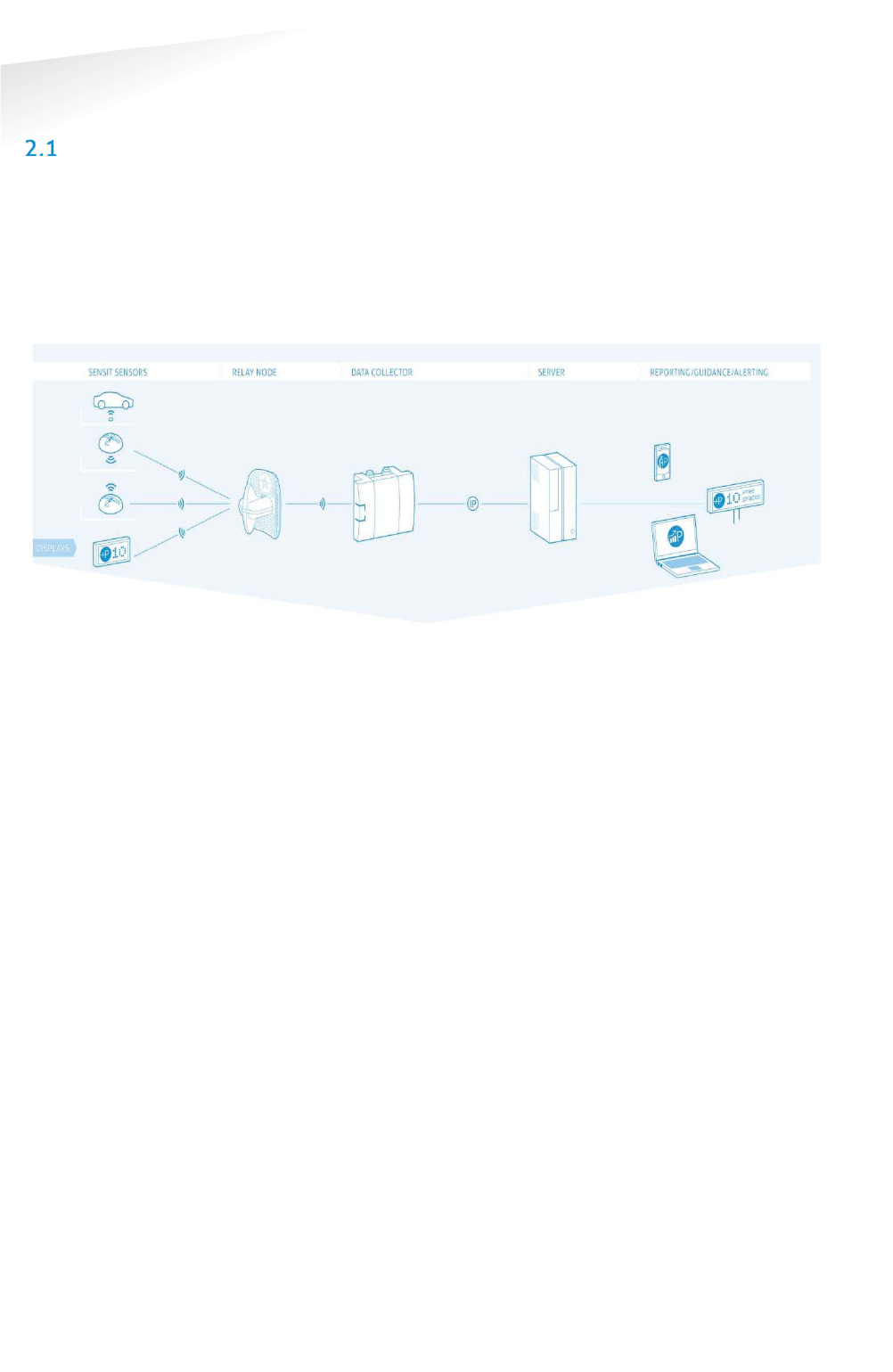
ARCHITECTURE
The actual status (occupancy) of the SENSIT sensors is finally collected by one or
more SENSIT Gateway. The SENSIT sensors transmit their status via one or more
Relay Nodes to the SENSIT Gateway. The SENSIT Gateway (formally known as Data
Collector) is the interface between the wireless sensors network and the SENSIT
Interface Software running on the server. The SENSIT Gateway transmits status
information about the sensors to the server using TCP/IP via Ethernet or GPRS
communication.
Figure 1: System Architecture
For a parking site you need at least one SENSIT Gateway, a Relay Node and a SENSIT
per parking bay.

SENSIT SYSTEM | MANUAL
SENSIT System
9/
111
S
EN
S
IT
Sy
ste
m
THE SENSIT SENSORS
Four types of ruggedly designed sensors are available to accommodate installation
in indoor car parks, on-street spaces and road surfaces. Until recently the standard,
most used, SENSIT Sensor is the SENSIT IR. For regions with lots of snow the SENSIT
Flush Mount is designed to withstand frequent snow ploughing. The SENSIT Surface
Mount is designed for indoor car parks or roof tops where drilling is not allowed.
For now all types will be available, in the future the standard SENSIT IR and SENSIT
Flush Mount will be replaced with the new SENSIT IR Flush Mount sensor.
2.2.1 SENSIT IR FLUSH MOUNT
Flush mount vehicle detection sensor featured with dual
detection technology (infrared and earth-magnetic field
detection. The sensor is resistant to snow ploughs and offers
vandal resistant installation.
SSENSIT Flush Mount
Operating
frequency
SENSIT IR FLUSH MOUNT EU: 868.2 MHz
SENSIT IR FLUSH MOUNT CN: 868.2 MHz
SENSIT IR FLUSH MOUNT US: 902-928 MHz (FHSS)
SENSIT IR FLUSH MOUNT AU: 915-928 MHz (FHSS)
SENSIT IR FLUSH MOUNT NZ : 920-925MHz (FHSS)
SENSIT IR FLUSH MOUNT SG : 920-925MHz (FHSS)
SENSIT IR FLUSH MOUNT ID: 923-925MHz (FHSS)
SENSIT IR FLUSH MOUNT MY : 919-923MHz (FHSS)
Detection
Magnetic and IR Accuracy: 98%
Load resistance
Heavy traffic
Mounting
Into the floor
Weight
350 gram (12.35 oz)
Dimensions Ø 78 mm (3.07 inch)
In the floor 72 mm (2.09 inch)
Color
Black
Detection height
0…90 cm (0 … 35.5 inch)
Protection
IP67, completely sealed housing PE
Operating
temperature
-40 ... +85°C (-40°F … +185°F)
Power supply Built in Lithium batteries expected lifetime of 5-10
years*
Antenna
Included
* Under normal circumstances and dependent on settings.
Note
The SENSIT IR Flush Mount
has a vandal resistance
design but of course brute
excessive force still can
damage the device.
.

SENSIT SYSTEM | MANUAL
SENSIT System
10/
111
S
EN
S
IT
Sy
ste
m
2.2.2 SENSIT IR
Vehicle detection sensor featured with dual detection
technology (infrared and earth-magnetic field detection. The
SENSIT IR is mounted into the floor of each parking space
allowing for vandal resistant installation, making the unit
suitable for on-street application.
SSENSIT IR
Operating
frequency
SENSIT IR EU: 868.2 MHz
SENSIT IR CN: 868.2 MHz
SENSIT IR US: 902-928 MHz (FHSS)
SENSIT IR AU: 915-928 MHz (FHSS)
SENSIT IR NZ : 920-925MHz (FHSS)
SENSIT IR SG : 920-925MHz (FHSS)
SENSIT IR ID: 923-925MHz (FHSS)
SENSIT IR MY : 919-923MHz (FHSS)
Detection
Magnetic and IR Accuracy: 98%
Load resistance
Heavy traffic
Mounting
Into the floor
Weight
365 gram (12.87 oz)
Dimensions Ø 78 mm (3.07 inch)
In the floor 55 mm (2.16 inch)
Above the floor 20 mm (0.79 inch)
Color
Black or Yellow (optional)
Detection height
0…90 cm (0 … 35.5 inch)
Protection
IP67, completely sealed housing PE
Operating
temperature
-40 ... +85°C (-40°F … +185°F)
Power supply Built in Lithium batteries expected lifetime of 5-10
years *
Antenna
Included
* Under normal circumstances and dependent on settings.
Note
The SENSIT IR has a vandal
resistance design but of
course brute excessive
force still can damage the
device.
.

SENSIT SYSTEM | MANUAL
SENSIT System
11/
111
S
EN
S
IT
Sy
ste
m
2.2.3 SENSIT FLUSH MOUNT
Vehicle detection sensor for flush mount installation in the
road surface. The sensor is resistant to snow ploughs and
offers vandal resistant installation. The SENSIT Flush Mount is
featured with earth-magnetic field detection.
SSENSIT Flush Mount
Operating
frequency
SENSIT FLUSH MOUNT EU: 868.2 MHz
SENSIT FLUSH MOUNT CN: 868.2 MHz
SENSIT FLUSH MOUNT US: 902-928 MHz (FHSS)
SENSIT FLUSH MOUNT AU: 915-928 MHz (FHSS)
SENSIT FLUSH MOUNT NZ : 920-925MHz (FHSS)
SENSIT FLUSH MOUNT SG : 920-925MHz (FHSS)
SENSIT FLUSH MOUNT ID: 923-925MHz (FHSS)
SENSIT FLUSH MOUNT MY : 919-923MHz (FHSS)
Detection
Magnetic Accuracy: 95%
Load resistance
Heavy traffic
Mounting
Into the floor
Weight
350 gram (12.35 oz)
Dimensions Ø 78 mm (3.07 inch)
In the floor 72 mm (2.09 inch)
Color
Black
Detection height
0…90 cm (0 … 35.5 inch)
Protection
IP67, completely sealed housing PE
Operating
temperature
-40 ... +85°C (-40°F … +185°F)
Power supply Built in Lithium batteries expected lifetime of 5-10
years*
Antenna
Included
* Under normal circumstances and dependent on settings.
Note
The SENSIT Flush Mount has
a vandal resistance design
but of course brute
excessive force still can
damage the device.
.

SENSIT SYSTEM | MANUAL
SENSIT System
12/
111
S
EN
S
IT
Sy
ste
m
2.2.4 SENSIT SURFACE MOUNT
Vehicle detection sensor designed for car parks
where drilling is not allowed or non-permanent
mounting is required. The unit is suitable for
indoor car parks and rooftop parking’s. The sensor
can easily be glued onto the surface. Replacement
can be achieved by removing the sensor installed
in the mounting ring. The SENSIT Surface Mount is featured with dual detection
technology (infrared and earth-magnetic field).
SSENSIT Surface Mount
Operating
frequency
SENSIT SURFACE MOUNT EU: 868.2 MHz
SENSIT SURFACE MOUNT CN: 868.2 MHz
SENSIT SURFACE MOUNT US: 902-928 MHz (FHSS)
SENSIT SURFACE MOUNT AU: 915-928 MHz (FHSS)
SENSIT SURFACE MOUNT NZ : 920-925MHz (FHSS)
SENSIT SURFACE MOUNT SG : 920-925MHz (FHSS)
SENSIT SURFACE MOUNT ID : 923-925MHz (FHSS)
SENSIT SURFACE MOUNT MY : 919-923MHz (FHSS)
Detection
Magnetic and IR Accuracy: 98%
Load resistance
Regular traffic
Mounting
On the floor surface
Weight
455 gram (16.05 oz)
Dimensions Mounting ring: Ø 240 (9.45 inch)
Sensor: Ø 167 cm (6.57 inch)
Height: 35mm (1.38 inch)
Color
Sensor black and yellow (optional black) ring
Detection height
0…90 cm (0 … 35.5 inch)
Protection
IP67, completely sealed housing PE
Operating
temperature
-40 ... +85°C (-40°F … +185°F)
Power supply Built in Lithium batteries expected lifetime of 5-9
years *
Antenna
Included
* Under normal circumstances and dependent on settings.

SENSIT SYSTEM | MANUAL
SENSIT System
13/
111
S
EN
S
IT
Sy
ste
m
RELAY NODES
A Relay Node allows for communication increase and ensures a robust and reliable
communication network. It ensures fast transmission of event messages from the
vehicle detection sensors to the SENSIT Gateway.
2.3.1 SENSIT RELAY NODE 2G
The Relay Node 2G is has an improved communication
range and a battery lifetime. It ensures a robust and reliable
communication network. The Relay Node 2G ensures fast
transmission of event messages from the SENSIT sensors to
the SENSIT Gateway. Relay Node 2G should be mounted
preferable at about 3 – 6 meters [10- 20 ft] from the floor
(e.g. onto a lamppost) to allow for visible view of the
sensors.
RRelay Node 2G
Operating
frequency
SENSIT RELAY NODE 2G EU: 868.2 MHz
SENSIT RELAY NODE 2G CN: 868.2 MHz
SENSIT RELAY NODE 2G US: 902-928 MHz (FHSS)
SENSIT RELAY NODE 2G AU: 915-928 MHz (FHSS)
SENSIT RELAY NODE 2G NZ : 920-925MHz (FHSS)
SENSIT RELAY NODE 2G SG : 920-925MHz (FHSS)
SENSIT RELAY NODE 2G ID : 923-925MHz (FHSS)
SENSIT RELAY NODE 2G MY : 919-923MHz (FHSS)
Weight
540 gram (12.87 oz)
Dimensions
200 x 170 x 204 mm (7.87 x 6.69 x 8.03 inch)
Mounting Onto a pole, lamppost or wall, mounting bracket
included.
Mounting height
3 – 6 meters (10 – 20 ft.)
Pole
dimensions
Min. Ø 40 mm (1.57 inch)
Max. Ø 150 mm (6 inch)
Protection
IP65
Operating
temperature
-40 ... +85°C (-40°F … +185°F)
Communication
range *
DC – RN 2G omnidirectional 35 m (135 ft)
DC – RN 2G directional max. 50 m (164 ft)
DC GPRS – RN 2G max. 10 m (33 ft)
RN 2G – RN 2G max. 100m (328 ft)
SENSIT – RN 2G omnidirectional 35 m (135 ft)
SENSIT – RN 2G directional 50 m (164 ft)
Power supply
**
Replaceable Lithium batteries expected lifetime of 5
years
Antenna
connection
Antenna included
* Dependent on the environment.
** Under normal circumstances and dependent on settings.
SENSIT SYSTEM | MANUAL
SENSIT System
14/
111
S
EN
S
IT
Sy
ste
m
SENSIT GATEWAY
The actual status (occupancy) of the SENSIT sensors is collected by one or more
Gateway. The Gateway is the interface between the wireless sensors network and
the SENSIT Interface Software running at the server. The Gateway transmits status
information about the sensors to the server using TCP/IP via Ethernet or 3G mobile
communication.
For a parking site you need at least one Gateway, a Relay Node and a SENSIT per
parking bay. One Gateway is required per 250 parking bays. All Gateway must be
separated as far as possible from each other, preferably at the remote corners of the
site.
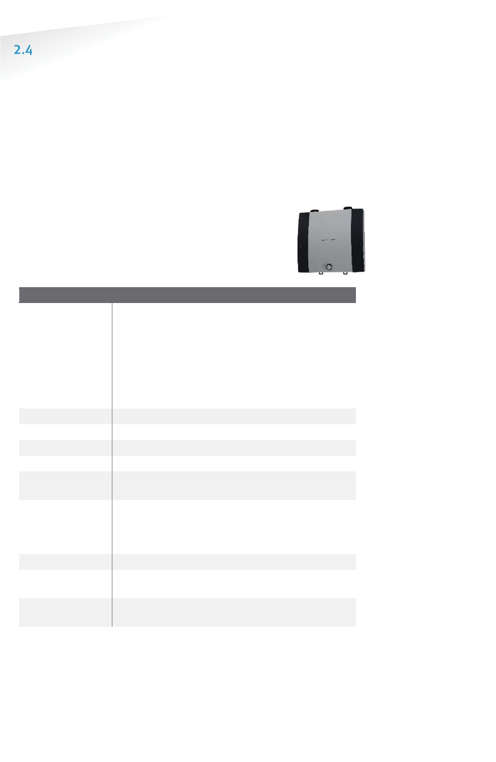
2.4.1 THE GATEWAY
The Gateway can be installed virtually anywhere due to its IP65
weatherproof housing and embedded 3G wireless modem. The only
requirements in case it is uses the mobile internet are; an AC mains
power supply and that it should be installed within reach of the
SENSIT wireless network.
SSENSIT Gateway
Operating
frequency
SENSIT GATEWAY EU: 868.2 MHz
SENSIT GATEWAY CN: 868.2 MHz
SENSIT GATEWAY US: 902-928 MHz (FHSS)
SENSIT GATEWAY AU: 915-928 MHz (FHSS)
SENSIT GATEWAY NZ : 920-925MHz (FHSS)
SENSIT GATEWAY SG : 920-925MHz (FHSS)
SENSIT GATEWAY ID : 923-925MHz (FHSS)
SENSIT GATEWAY MY : 919-923MHz (FHSS)
Dimensions
252 x 251 x 89 mm (10 x 10 x 3.5 inch)
Weight
1850 gram (65 oz)
Protection
IP65
Color
Aluminum & dark blue side covers RAL5011
Operating
temperature
-40°C … +65°C (-40°F … +149°F)
Communication
range*
From SENSIT to Gateway in principle unendless as the
nodes communicate to each other. It is recommended to
locate the nearest Relay Node within 25 meters (82
ft)
of the Gateway.
Communication
3G mobile or RJ45 TCP/IP
Power input 110-240 VAC 50/60Hz or
12VDC (solar panel set)
Antenna
connection
Antenna included
* Dependent on the environment.
2.4.2 GATEWAY COMMUNICATION BACKUP
When both connection means are in place; as well Ethernet as the 3G modem by
default the Gateway will connect via the Ethernet to the SIS. When the Ethernet
connection fails the communication automatically will fall back to the 3G modem.
SENSIT SYSTEM | MANUAL
SENSIT System
15/
111
S
EN
S
IT
Sy
ste
m
2.4.3 GATEWAY EVENT BUFFER
Furthermore the Gateway is equipped with an event buffer to store up to 24k
events. This memory stores the events in case both communication means
temporary fails. As soon as the communication is restored the Gateway will transmit
the buffered events.
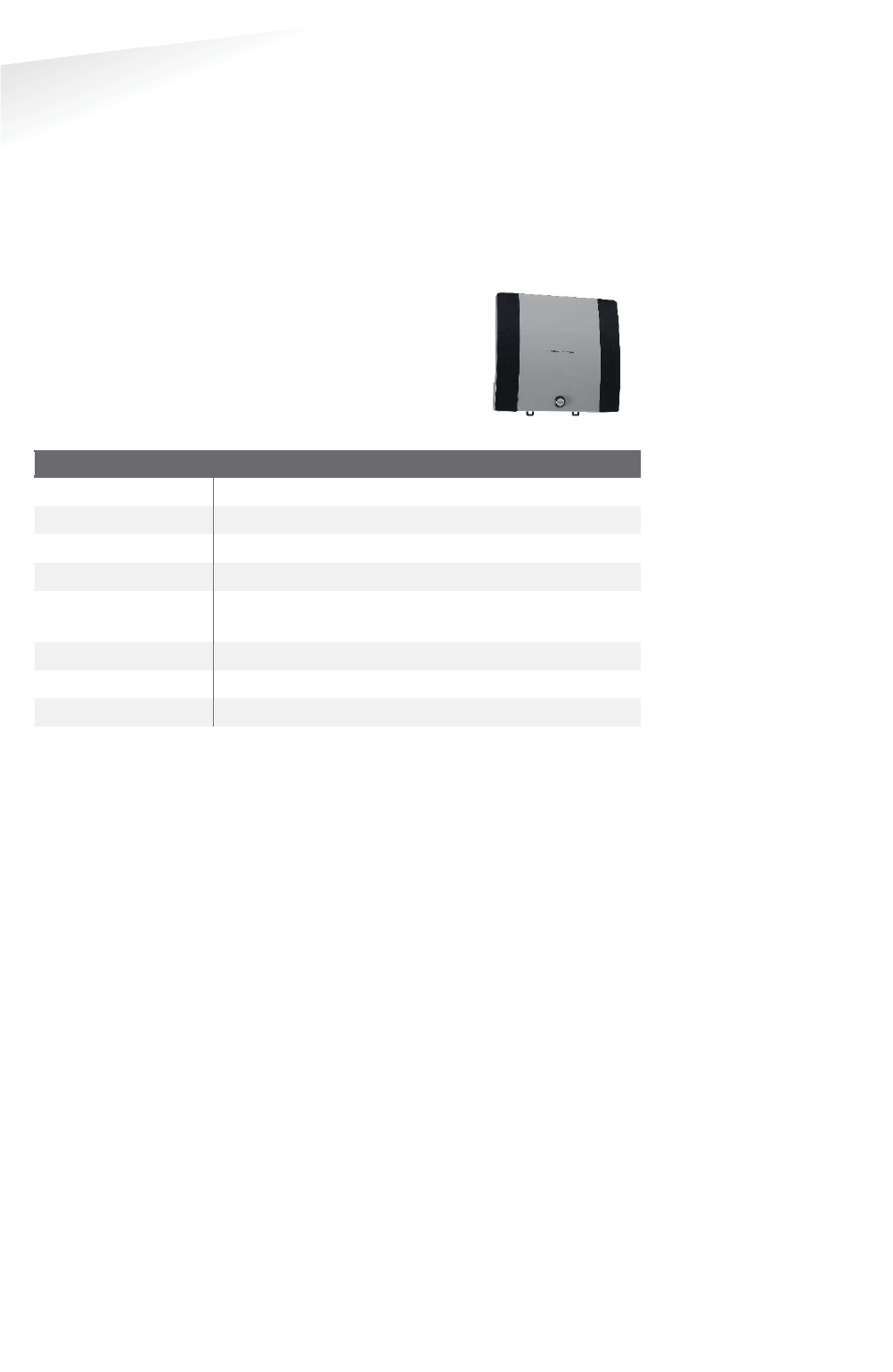
2.4.4 SENSIT BACKUP BATTERY
The Gateway can be completed with a backup battery to make
sure the Gateway stays alive when the mains power fails. This
backup battery can also been used when the Gateway is
powered by the public lighting pole. This cyclic use will have
an influence on the lifetime of the internal lead-acid battery.
SSENSIT BBattery ppack
Dimensions
252 x 251 x 89 mm (10 x 10 x 3.5 inch)
Weight
3800 gram (134 oz)
Protection
IP65
Color
Aluminum & dark blue side covers RAL5011
Operating
temperature
-15°C … +50°C (5°F … +122°F)
Internal battery
12VDC | 7Ah (lead-acid)
Lifetime*
>1000 discharge/charge cycles
Autonomous time**
Up to 35 hours
* Depends upon the average depth of discharge.
** Depends upon communication means 3G/Ethernet, temperature and battery age
Note
By defau
lt the Gateway
event buffer is disabled. At
least version 1.6 has to be
installed at your SIS before
the event buffer function
can work.
.
SENSIT SYSTEM | MANUAL
SENSIT System
16/
111
S
EN
S
IT
Sy
ste
m
ADDITIONAL EQUIPMENT
Additional equipment is available to expand the functionality of the SENSIT system.
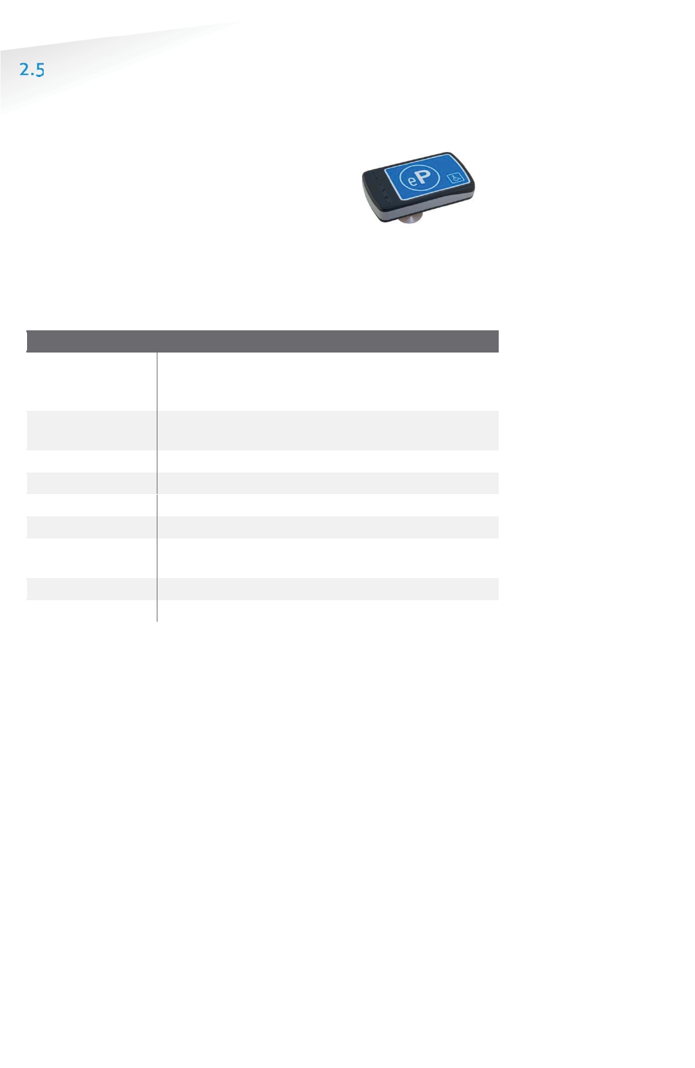
2.5.1 ELECTRONIC PARKING LICENSE
The Electronic Parking License (EPL) physically is a
device that is positioned inside the car. Whenever the
car stops for a specific period of time it considers the
car to be parked and it will look for a wireless SENSIT
network. If a network is detected, it will make itself
know to the network. Its unique EPL identifier is
registered at the server with SENSIT Interface Software (SIS). The SIS is triggered
when parking bays that require a license change status (become occupied or free).
When such a parking bay is occupied the system will calculate the odds of the
parking bay being occupied by an unauthorized vehicle.
EElectronnic Parking License
Operating
frequency
SENSIT EPL EU: 868.2 MHz
SENSIT EPL US: 902-928 MHz (FHSS)
SENSIT EPL AU: 915-928 MHz (FHSS)
Mounting Attaches with suction pads to the windscreen on the
inside of the car
Weight
120 gram (4.2 oz)
Dimensions
116 x 72 x 27 mm (4.6 x 2.8 x 1.1 inch)
Color
Grey, RAL7016
Protection
IP32
Operating
temperature
-40 ... +85°C (-40°F … +185°F)
Power supply
User replaceable AAA 1.5V alkaline batteries
Antenna
Included

SENSIT SYSTEM | MANUAL
SENSIT System
17/
111
S
EN
S
IT
Sy
ste
m
2.5.2 SENSIT DISPLAY
The SENSIT Display enables signage of available parking
spaces for stand-alone parking guidance installations.
The display is designed for outdoor use, indicating the
number of available parking spaces per parking lot thus
guiding motorists to the closest parking space.
Availability of parking spaces can be indicated per zone,
for the specific zone the SENSIT Display is allocated to. Configuration of the display
can be realized using the SENSIT Interface Software.
SSENSIT Display
Display
Graphical display for outdoor use, single sided
Dimensions
330 x 221 x 171 mm (13.0 x 8.7 x 6.7 inch)
Display
dimensions
320 x 160 x 15 mm
(12.6 x 6.3 x 0.6 inch)
Weight
5900 gram (208 oz)
Protection
IP65, UV protected
Color
Stainless steel housing, Amber LEDs
Character height
160 x 100 mm [h x w] (6.3 x 3.9 in)
Number of digits
3
Readability
5.000 cd/m2, readable in full sunlight.
Luminance
Ambient light luminance regulation.
Viewing angle
70º/35º
Operating
temperature
-20 ... +60°C (32°F … +122°F)
Power supply 110-230 VAC 50/60Hz or
PoE+ (25W)
Relay outputs
3 Low voltage relays

SENSIT SYSTEM | MANUAL
SENSIT System
18/
111
S
EN
S
IT
Sy
ste
m
2.5.3 SENSIT CONFIGURATION TOOL
The SENSIT Configuration Tool can be used during installation of
the SENSIT system. This tool enables easy installation;
segmentation, calibration and administration (CVS-file including
GPS-coordinates) of the SENSIT equipment (SENSIT Gateways,
Relay nodes and sensors). The SENSIT The Configuration Tool
works with an App which must be installed on an Android
smartphone. This App, called ‘SENSIT Configurator’ is available in
the google play store. The communication between the App and Configuration Tool
is over Bluetooth.
SSENSIT Configuration Tool
Dimensions
200 x 115 x 93 mm (7.9 x 5.9 x 2.4 inch)
Weight
505 gram (17.8 oz)
Protection
IP44
Color
Yellow housing, black front
Communication
Bluetooth
Operating
temperature
-10 ... +50°C (14°F … +122°F)
Battery powered
2x 1.5V AA alkaline batteries
Lifetime About 40 hours of continuous use on a set of AA
alkaline batteries.

SENSIT SYSTEM | MANUAL
SENSIT System
19/
111
S
EN
S
IT
Sy
ste
m
SENSIT INTERFACE SOFTWARE
SENSIT Interface Software allowing easy system integration into enforcement, traffic
guidance or parking guidance management application. The main features of the
SENSIT Interface Software to help you and make easy system integration possible
are:
x Installation
x Configuration
x Basic administration
x Integration
The SENSIT Interface Software enables easy installation of the wireless sensor
network. Once the network and sensors are installed, the sensors will automatically
appear in the software. Configuration of sensors to specific parking bays, parking
zone and parking lot can easily be realized.
Additionally the software configures and monitors communication of the SENSIT
node network. It monitors the data transfer between the sensors and the SENSIT
Gateways. Moreover it also analyzes communication reliability of the sensor network
in a graphical map, automatically alerting areas for maintenance.
Easy integration can be done via SOAP, REST or REST Hooks interface.
SOAP or Simple Object Access Protocol, is a protocol specification for exchanging
structured information. It relies on Extensible Mark-up Language (XML) for its
message format.
The SOAP interface can query data from the SIS using the http(s) interface, the found
data is returned in a XML description format.
Representational state transfer (REST) is a simple stateless architecture that
generally runs over HTTP(S). REST involves reading a designated Web page that
contains an XML file. The XML file describes and includes the desired content.

SENSIT SYSTEM | MANUAL
Installation Procedures
20/
111
In
st
al
la
ti
on
P
ro
ce
du
re
s
3 INSTALLATION PROCEDURES
The installation of the SENSIT system is basically the same with or without a
Configuration Tool and can be described in 4 major steps: The preparation, the
installation of Gateways and Relay Nodes, the installation of SENSIT sensors and
finally setting up the SENSIT Interface Software.
In the next 2 paragraphs both methods are describe; with- or without the
Configuration Tool. The functionality and used of the Configuration tool is described
in more detail in chapter 5.
4-STEPS WITHOUT THE CONFIGURATION TOOL
3.1.1 STEP 1 – PREPARATION
a. Arrange a scaled map of the site.
b. Make a site inspection to gather information:
x Draw on the map where the parking bays are located.
x Draw on the map where you can mount Relay Nodes
x Draw on the map the possible locations for the Gateway.
c. Make an installation plan:
x Number every parking bays with a unique number.
x Use the Relay Node Tool to plan the final Relay Node and Gateway
locations to form a covering network.
3.1.2 STEP 2 – GATEWAY AND RELAY NODE INSTALLATION
a. Install and power-up the Gateway according the plan.
b. Activate and install the Relay Nodes according the plan.
c. Write the ID numbers of the Gateways and Relay Nodes at the right location
in the plan.
d. Verify at the server that all Gateways and Relay Nodes are online.
3.1.3 STEP 3 – SENSIT INSTALLATION
a. Free the bays and close off the parking area.
b. Mark the right location at the road surface with a piece of chalk or paint.
c. Distribute the SENSIT sensors at the, to be installed locations and activate
them with the magnet.
d. Make a list of the correct ID numbers and bay numbers.
e. Verify at the server if all SENSIT sensors come online.
f. Drill the holes and glue the SENSIT sensors.
g. Calibrate the SENSIT sensors without cars or metal tools in the
neighborhood of the SENSIT’s.
3.1.4 STEP 4 – SETTING UP THE SENSIT INTERFACE SOFTWARE
a. Make a (simple) Inkscape drawing of the site based on the map and
gathered information during STEP 1 and STEP 2.
x Draw the Relay Nodes and Gateways at the right locations
x Draw the bays at the right locations
b. Upload the SVG-drawing to the server.
c. Make a correct CSV-file and upload it to the server.
d. Verify if all Gateways, Relay Nodes and SENSIT sensors show up correctly in
the system.
Note
There i
s also a planning-
tool
(RelayNodeTool)
available to plan the Relay
Node and Data Collector
locations.
See chapter
below for an example.
Note
Ask your Nedap account
manager for special
installation tools to
configure, calibrate
and
register the ID to bay
bindings.
Note
Inkscape is an open
-
source
drawing program to create
the SVG (Scalable Vector
Graphic) drawing.
Note
Relay Node Tool is a
planning
-tool, to design
the
Relay Node and
Gateway
locations.
See chapter
below for an example.
.
Note
Inkscape is an open
-
source
drawing program to create
the SVG (Scalable Vector
Graphic) drawing.

SENSIT SYSTEM | MANUAL
Installation Procedures
21/
111
In
st
al
la
ti
on
P
ro
ce
du
re
s
4-STEPS WITH THE CONFIGURATION TOOL
As mentioned the installation of a SENSIT system with a Configuration tool is similar
as the configuration without a tool and can also be described in 4-steps: The first
and last step is exactly the same, the configuration of SENSIT Gateways, Relay Nodes
and SENSIT sensors is automated with the Configuration Tool to prevent writing
errors, automatic calibration and to make segmentation possible.
3.2.1 STEP 1 – PREPARATION
a. Arrange a scaled map of the site.
b. Make a site inspection to gather information:
x Draw on the map where the parking bays are located.
x Draw on the map where you can mount Relay Nodes
x Draw on the map the possible locations for the Gateway.
c. Make an installation plan:
x Number every parking bays with a unique number.
x Use the Relay Node Tool to plan the final Relay Node and Gateway
locations to form a covering network.
3.2.2 STEP 2 – GATEWAYS AND RELAY NODE INSTALLATION
a. Install and power-up the Gateway according the plan.
b. Use the Configuration Tool for activation, segmentation and registration of
the Gateway.
c. Install the Relay Nodes according the plan.
d. Use the Configuration Tool for activation, segmentation and registration of
the Relay Nodes.
e. Verify at the server that all Gateways and Relay Nodes are online.
3.2.3 STEP 3 – SENSIT INSTALLATION
a. Free the bays and close off the parking area.
b. Mark the right location at the road surface with a piece of chalk or paint.
c. Drill the holes and glue the SENSIT sensors.
d. Use the Configuration Tool for activation, segmentation, calibration and
registration of the SENSIT sensor. Make sure there are no cars or metal tools
in the neighborhood of the SENSIT sensors.
3.2.4 STEP 4 – SETTING UP THE SENSIT INTERFACE SOFTWARE
a. Make a (simple) Inkscape drawing of the site based on the map and
gathered information during STEP 1 and STEP 2.
x Draw the Relay Nodes and Gateways at the right locations
x Draw the bays at the right locations
b. Upload the SVG-drawing to the server.
c. Use the data received from the configuration tool app and make a correct
CSV-file after upload it to the server.
d. Verify if all Gateways, Relay Nodes and SENSIT sensors show up correctly in
the system.
Note
Relay Node Tool is a
planning
-tool, to design
the
Relay Node and
Gateway
locations.
See chapter 4
for
an example.
Note
In chapter
5 a more
detailed description about
the configuration tool and
how it works can be found.
Note
Inkscape is an open
-
source
drawing program to create
the SVG (Scalable Vector
Graphic) drawing.
SENSIT SYSTEM | MANUAL
RelayNodeTool
22/
111
Rela
y
NodeTool
4 RELAYNODETOOL
The RelayNodeTool software is developed to get a good estimation of the needed
system components; Gateways and Relay Nodes. The estimation of needed
components is based on drawings of the site. In this way you are able to get a good
idea of the needed components.
In this example we are going to design the SENSIT system for two segments; the
parking basement and the outside parking terrain at the Nedap Headquarter office.
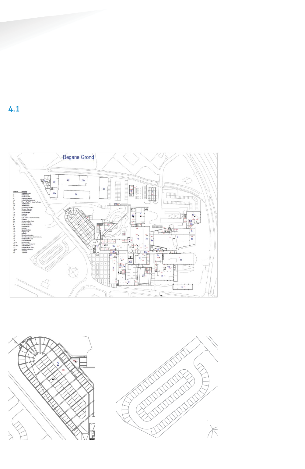
SCALED DRAWING
First get a drawing of the parking lot(s) and find out if it are open areas or closed
(indoor) areas. Try to get information about mounting locations, like lampposts and
poles for Relay Nodes and power and internet for the Gateway. Below you can find a
map of the Nedap Headquarter office, with its parking areas.
Figure 2: Example drawing of parking lots.
The drawing of a segment can be copied out of the larger map e.g. via the standard
Snipping Tool of Windows.
Figure 3: The Basement and the outside area.
Note
Please keep in mind that
with help of this
RelayNodeTool you can
determine the needed
components, but it will
always be an estimation.
SENSIT SYSTEM | MANUAL
RelayNodeTool
23/
111
Rela
y
NodeTool
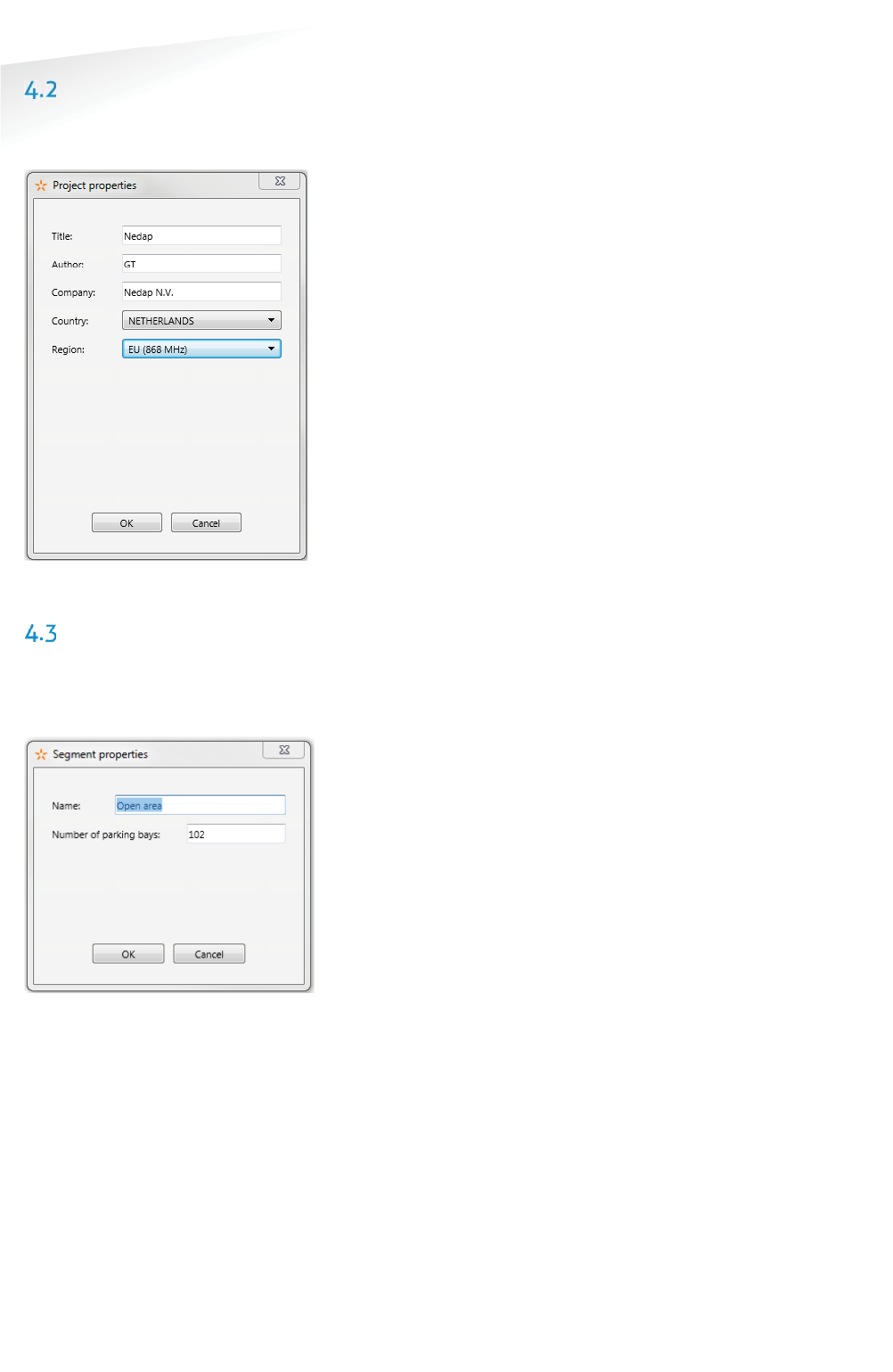
START A NEW PROJECT
Fill-in the project details; the project title, your name and you company name. Please
also indicate the country and region where the project is situated.
Figure 4: RelayNodeTool: Project details
THE FIRST SEGMENT
Via the option Segment -> Add new segment, or click on the tab <new> you can add
a segment to the design. Fill-in the segment properties; the segment name and the
number of parking bays.
Figure 5: RelayNodeTool: Segment properties
Note
The Relay Node Tool will
give you a warning if you
have more than 500 bays in
a segment. With more than
500 bays, segmentation is
necessary. Please contact
your
Nedap account
manager
for more
information.

SENSIT SYSTEM | MANUAL
RelayNodeTool
24/
111
Rela
y
NodeTool
4.3.1 IMPORT MAP
First import the drawing via the Paste from clipboard option or open the map image
file.
Figure 6: RelayNodeTool: Map import.
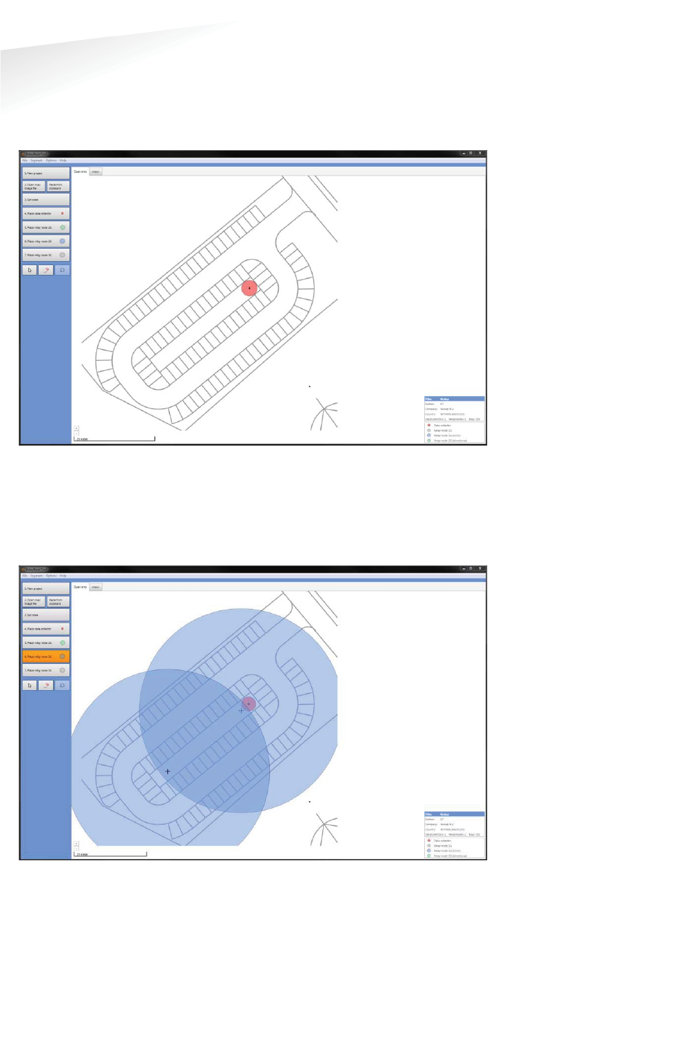
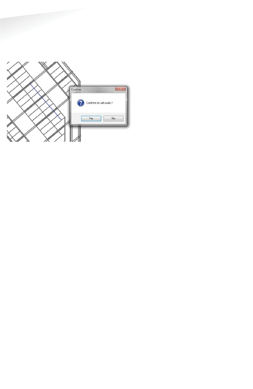
4.3.2 SET THE SCALE
Now set the scale, for an open area you set it at 25m if there isn’t a clear indication
about the size you can use the width of 10 parking bays:
Figure 7: RelayNodeTool: Scaling of the map.
SENSIT SYSTEM | MANUAL
RelayNodeTool
25/
111
Rela
y
NodeTool
4.3.3 PLACE THE GATEWAY
Place at least one Gateway for every 250 bays. Use the information you already
gathered or ask the client for the installation options for the Gateway(s). At least you
need a power connection and an internet connection in case of Ethernet.
Figure 8: RelayNodeTool: SENSIT Gateway placement.
4.3.4 PLACE THE RELAY NODE
Place the Relay Nodes at locations were you can mount it e.g. at lampposts in a way
that it covers all parking bays. With the tool you can choose between Relay Nodes
2G omni- or directional..
Figure 9: RelayNodeTool: RelayNode placement.
Note
The Relay Node Tool will
give you a warning if you
have more than 16 Relay
Nodes in a segment. With
more than 16 Relay Nodes,
segmentation might be
necessary. Please contact
your
Nedap account
manager
for more
information.
SENSIT SYSTEM | MANUAL
RelayNodeTool
26/1
11
Rela
y
NodeTool
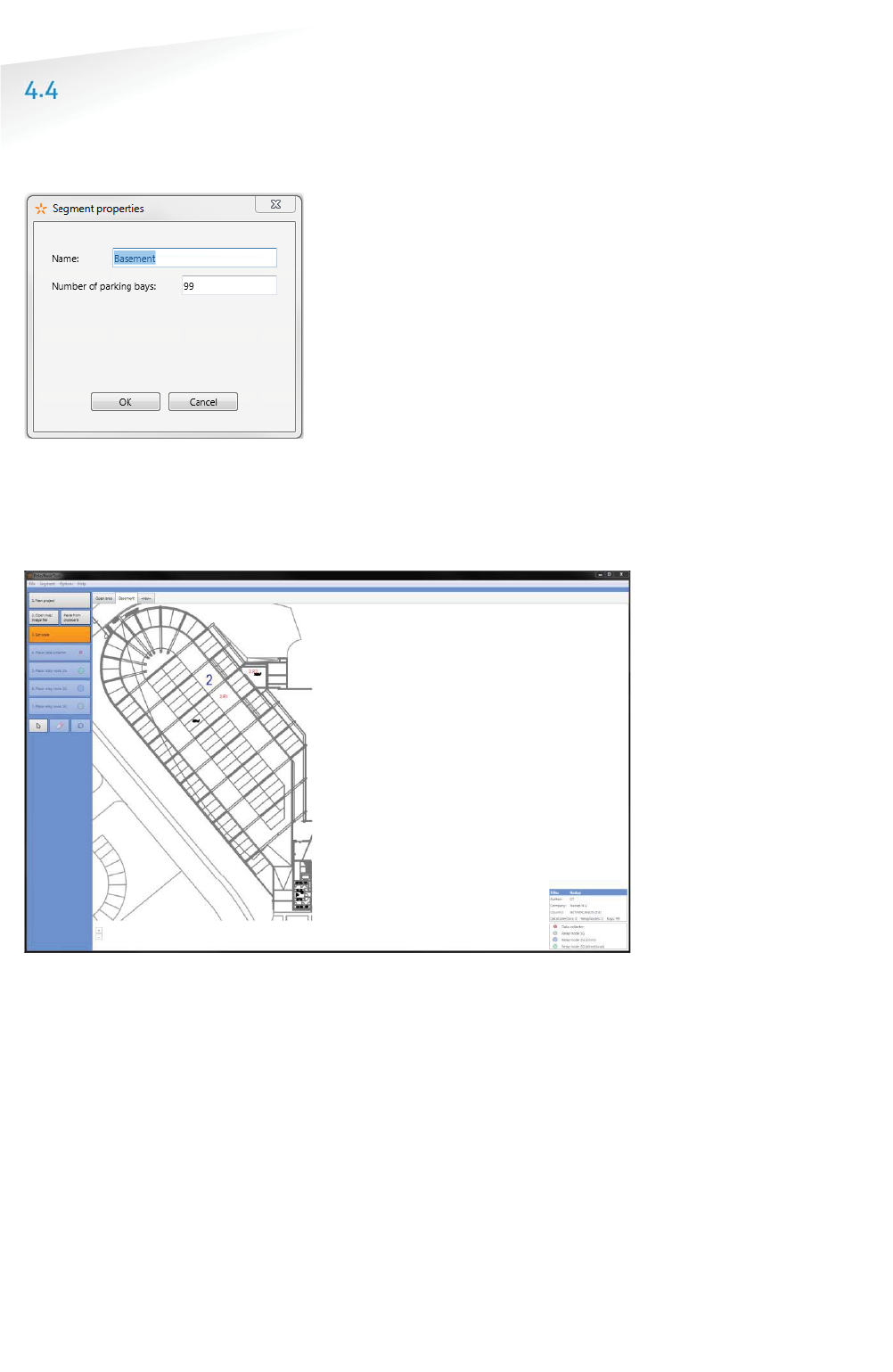
THE SECOND SEGMENT
Via the option Segment -> Add new segment, or click on the tab <new> you can add
a segment to the design. Fill-in the segment properties; the segment name and the
number of parking bays.
Figure 10: RelayNodeTool: Segment properties
4.4.1 IMPORT MAP
Also import the drawing for the second segment via the Paste from clipboard option
or open the map image file.
Figure 11: RelayNodeTool: Map import for the second segment.
SENSIT SYSTEM | MANUAL
RelayNodeTool
27/
111
Rela
y
NodeTool
4.4.2 SET THE SCALE
Also Set the scale, this location is a parking basement with a roof, large concrete
columns and walls. This will influence the range of the Relay Nodes and therefore
we advise to reduce the range with about 20%, so set the range to about 20m e.g.
the width of 8 parking bays.
Figure 12: RelayNodeTool: Scaling of the map.
4.4.3 PLACE THE GATEWAY
Because this basement parking area is half open we can use the Gateway of the
open area, so we don’t need to add one for this segment.
SENSIT SYSTEM | MANUAL
RelayNodeTool
28/
111
Rela
y
NodeTool
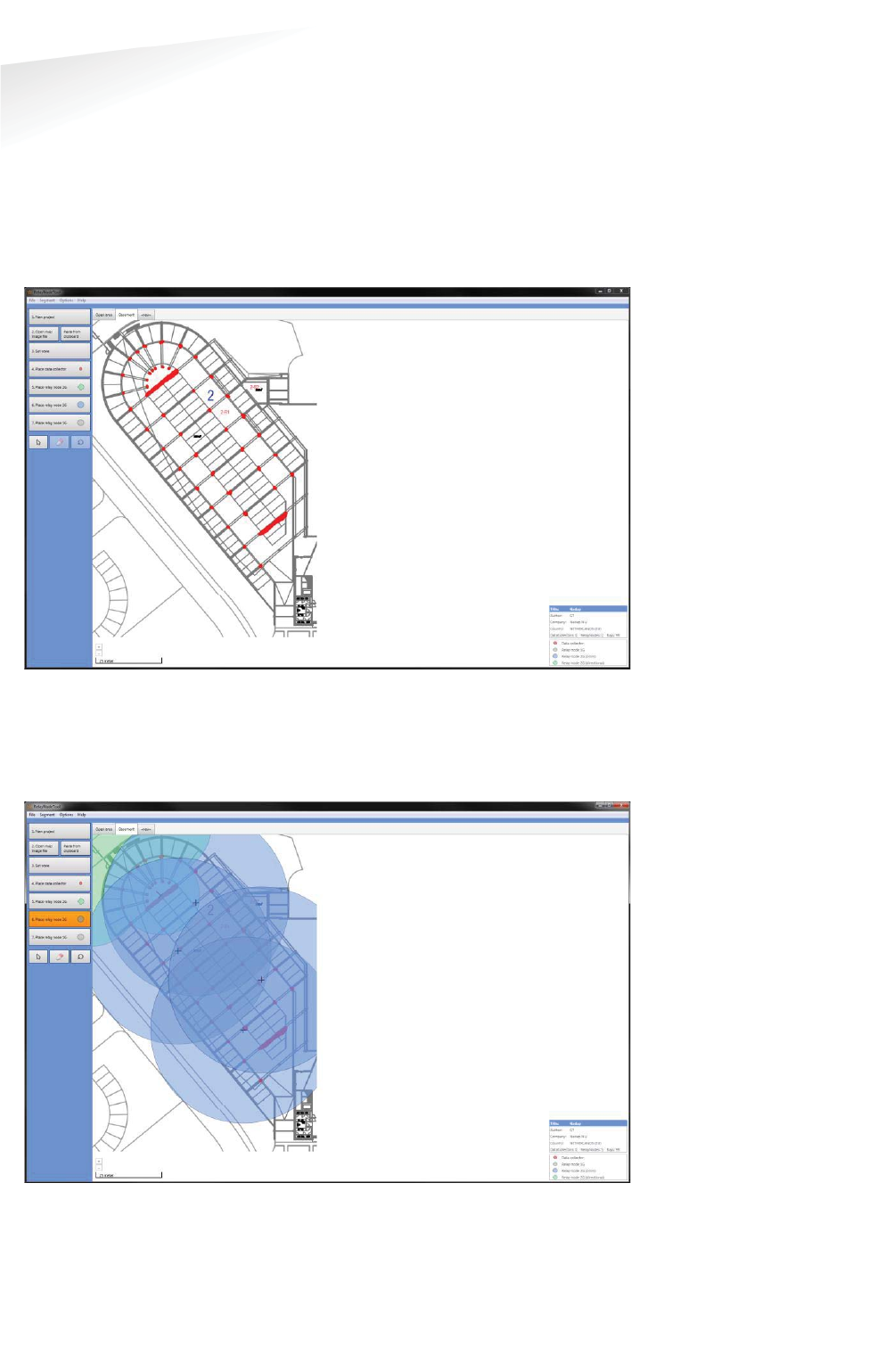
4.4.4 PLACE THE RELAY NODE
Place the Relay Nodes at locations were you can mount it e.g. at lampposts in a way
that it covers all parking bays. With the tool you can choose between Relay Nodes
2G omni- or directional.
There are 2 large concrete walls and after every 3 parking bays there is large
concrete pillar, all is indicated with red. This will influence the range and radiation
pattern of the Relay Nodes.
Figure 13: Imported map with concrete wall and pillar indication.
Probably with only 3 Relay Nodes 2G it is possible to get coverage of all bays, but
because of these large influencing concrete objects we used 2 Relay Nodes 2G extra
to make sure all SENSIT sensors are sufficient reachable.
Figure 14: RelayNodeTool: RelayNode placement
SENSIT SYSTEM | MANUAL
RelayNodeTool
29/
111
Rela
y
NodeTool
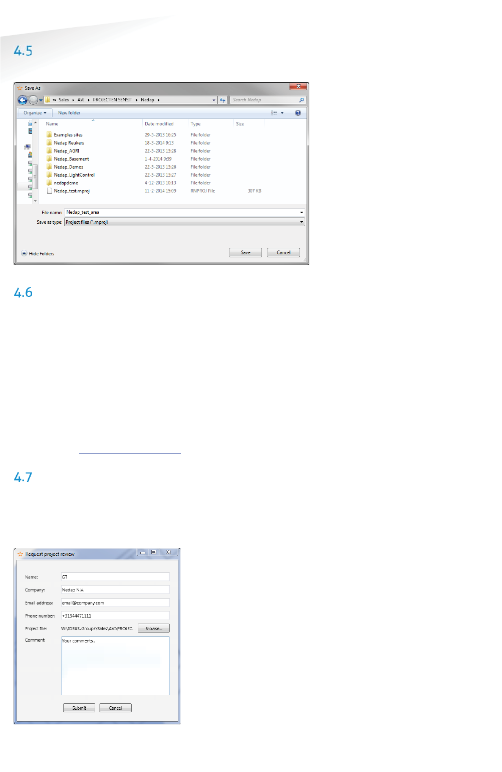
SAVE THE PROJECT
Now you can save the project file:
Figure 15: RelayNodeTool: Project save.
EXPORT PROJECT FILES
4.6.1 PROJECT FILE
You can send the project file (*.rnproj) to a colleague or Nedap so it can be
reviewed.
4.6.2 SAVE AS IMAGE
You can save the segments you have designed to an image file, via the option File ->
Save image (current segment and use it in your offer.
4.6.3 PRINT PROJECT
You can print the project file to a normal printer or to a PDF printer like the free PDF
writer CutePDF (http://www.cutepdf.com/) and use this in your offer.
REQUEST PROJECT REVIEW
You can also request Nedap to review the project you have designed. Fill-in: your
name, company, email address and phone number and write your comments on the
design. With this information and the automatically added *.rnproj file Nedap can
give you advise on the design.
Figure 16: RelayNodeTool: Project review request
SENSIT SYSTEM | MANUAL
Configuration tooL
30/
111
Con
f
i
g
uration too
L
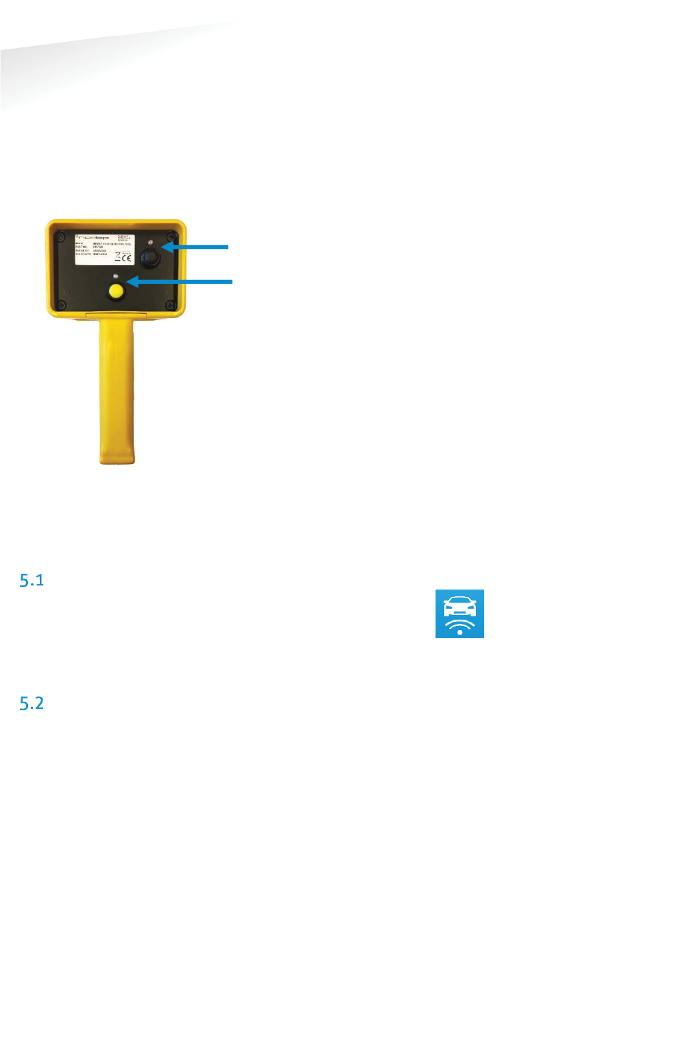
5 CONFIGURATION TOOL
The SENSIT Configuration Tool can be used during installation for the following
functionalities: Creating a CSV file, Storing the GPS coordinates, starting or restarting
the SENSIT Gateways, SENSIT sensors and Relay Nodes, Calibrating sensors and
dividing larger parking areas into segments.
Please find below a figure of the Configuration Tool with a small description.
Figure 17: Configuration tool.
The Configuration Tool is equipped with two buttons and feedback LED’s. The Tool is
powered with the black button, the green LED will light-up. The reader is started
with the yellow button, the red LED will flash will the reader is active.
DOWNLOADING THE APP
The SENSIT Configuration Tool works with an Android app. This app,
called ‘SENSIT Configurator’ is available in the Google Play Store. The app
and SENSIT Configuration Tool use Bluetooth to communicate. Make sure
Bluetooth is enabled on your smartphone.
STARTING THE CONFIGURATION TOOL AND
INITIALIZE THE APP
1) Start the Configurator app on the Android smartphone
2) Turn on the Configuration Tool by pressing the black ON/OFF button, the
green LED will light up.
3) Following steps are done on the app: Navigate to Options > Pair Device.
Scan for devices. Connect to the device with the Bluetooth name that can
be found on the label of the SENSIT Configuration Tool.
4) Wait until the tool name appears on the display of the smartphone.
5) Make sure the memory in the app is cleared before making a start: navigate
to List Configured Nodes > Clear.
6) Check the segment setting, before configuring the first node. Navigate to
Settings > General Settings > Set Segment ID > Select Segment ID. Segment
0 is the default value.
7) The tool is now ready for use. It is important to use the following
commissioning sequence: first configure the SENSIT Gateways, second the
Relay Nodes and finally the SENSIT sensors.
ON/OFF
Read
Note
Make sure d
uring the
calibration process
, no
vehicles or metal parts are
in the parking bay or in the
adjacent parking bays. Keep
the SENSIT Configuration
Tool and any steel objects,
like safety shoes, at least 2
meters away from the
SENSIT sensor.
Note
At the portal an E-learning
course about the Tools can
be found, in here also the
Configuration Tool is
explained.

SENSIT SYSTEM | MANUAL
Configuration tooL
31/
111
Con
f
i
g
uration too
L
CONFIGURE THE GATEWAY
1) To configure Gateway, navigate to Manual Input
2) Enter the node ID, which can be found on backside of the Gateway and
select Program Node.
3) Restart the Gateway by switching off the power for a few seconds. The app
will detect that the SENSIT Gateway is starting up and will start the
configuration sequence. The selected segment and GPS position will be
programmed and saved in the List Configured Nodes.
4) When the app shows OK, the SENSIT Gateway is ready for use.
5) Repeat this process for all Gateways. Make sure to check the segment
number before configuring the Gateways.
CONFIGURE THE RELAY NODES
1) To configure the Relay Nodes, press the yellow button of the SENSIT
Configuration Tool. During 20 seconds, the SENSIT Configuration Tool is
active (red LED blinks).
2) Move the SENSIT Configuration Tool up and down over the front surface of
the Relay Node. The Relay Node ID is detected and configuration is started
automatically. During the configuration, the GPS position is stored in the
app and the node segment is set.
3) After OK is indicated, the Relay node is ready for use.
4) Repeat this process for all Relay Nodes. Make sure to check the segment
number before configuring the Relay Nodes
CONFIGURE SENSIT
1) To configure the SENSIT sensors, start with the sensor in the first parking
bay on the map in the SIS.
2) Press the yellow button of the SENSIT Configuration Tool. During 20
seconds, the SENSIT Configuration Tool is active (red LED blinks).
3) Rotate the SENSIT Configuration Tool over the surface of the sensor.
4) The SENSIT is activated and the ID number will appear in the app. The ID
number and GPS coordinate are stored in the app and the sensor
calibration is started.
5) When the display indicates OK, the sensor is ready for use.
6) Repeat this process for all SENSIT sensors by following the bay numbers
sequentially. Make sure to check the segment number before configuring
the SENSIT sensors.
SIS SOFTWARE
After configuring the SENSIT components, the stored app data must be transmitted
to the SIS Software. Therefore go to ‘list configured nodes’, check the list and select
‘Export’. Select the media of your choice and send the data. The message contains a
file in CSV format which can be loaded into the SIS software.
SENSIT SYSTEM | MANUAL
Configuration tooL
32/
111
Con
f
i
g
uration too
L
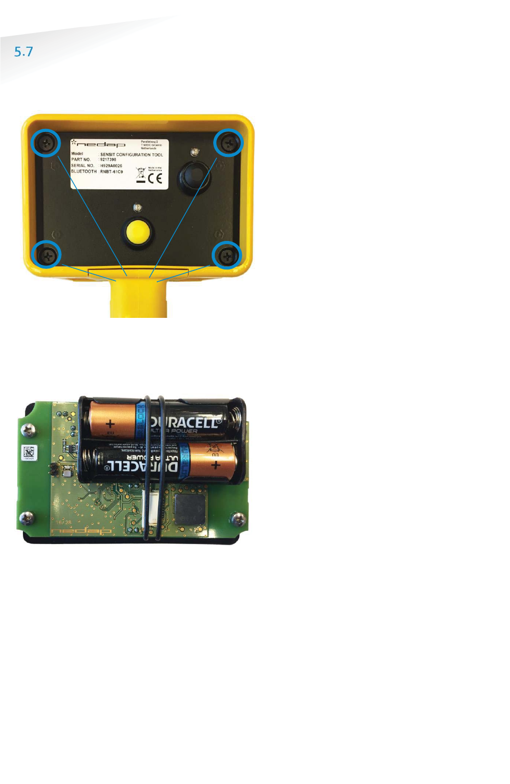
REPLACING THE BATTERIES
The lifetime of the 2x 1.5V AA alkaline batteries is about 40 hours of continuous use.
The batteries can be replaced by a new set of batteries. For this the housing has to
be opened, first remove the 4 screws at the front plate.
Figure 18: Configuration tool remove screws to open housing
Now the front plate including the electronics can be removed out of the housing.
Disconnect the reader antenna before you can completely remove the front
including the batteries and electronics.
Figure 19: Configuration tool: Battery replacement
Before the batteries can be removed the rubber strap has to be loosened. Replace
the empty batteries with 2 new 1.5V AA-type alkaline batteries, make sure the
polarity is correct. Reinstall the rubber strap and reconnect the reader antenna
before you close the housing again.
4--screws
Note
Be careful when you open
the housing and make sure
the RFID antenna is
disconnected before you
completely open the
housing to replace the
batteries.

SENSIT SYSTEM | MANUAL
Installation SENSIT Gateway
33/
111
Installation SENSIT Gatewa
y
6 INSTALLATION SENSIT GATEWAY
The SENSIT Gateway is available in one versions equipped with as well Ethernet as a
3G modem. The installation of the SENSIT Gateway is described in chapter 6.3.
SAFETY PRECAUTIONS
The following safety precautions should be observed during normal use, service and
repair.
x The SENSIT Gateway may only be installed and serviced by qualified service
personnel.
x Installation should be conducted according national wiring rules.
x An external readily accessible disconnect device shall be incorporated into
the installation of the equipment.
x Disconnect the power supply before removing or installing any parts.
x To be sure of safety, do not modify or add anything to the SENSIT Gateway
other than mentioned in this manual or indicated by NEDAP N.V.
IC AND FCC ID
FCC ID: CGDSENSITGATEWAY and IC: 1444A-SENSITGATEWAY
GATEWAY INSTALLATION
6.3.1 INSTALLATION CONDITIONS
The installation recommendation is based on the following environmental
conditions;
x Dry weather conditions.
6.3.2 REQUIRED INSTALLATION MATERIALS
The following would be required for mounting of the SENSIT Gateway. In case of wall
mounting.
x Special Equipment: Ladder, Bucket-truck or an aerial platform
x Power drill
x Set screw driver
x Wall plugs or anchors including screws
x Mains disconnect device
x Round double wire cable with a minimum diameter of 5 mm (0,2 inch).
x External disconnect device is needed.
x External 6A slow blow circuit breaker is recommended.
x In case of a wired Ethernet a shield RJ45 cable.
The needed materials for pole mounting are described at chapter 9.
Disconnect power
before servicing
the device.
SENSIT SYSTEM | MANUAL
Installation SENSIT Gateway
34/
111
Installation SENSIT Gatewa
y
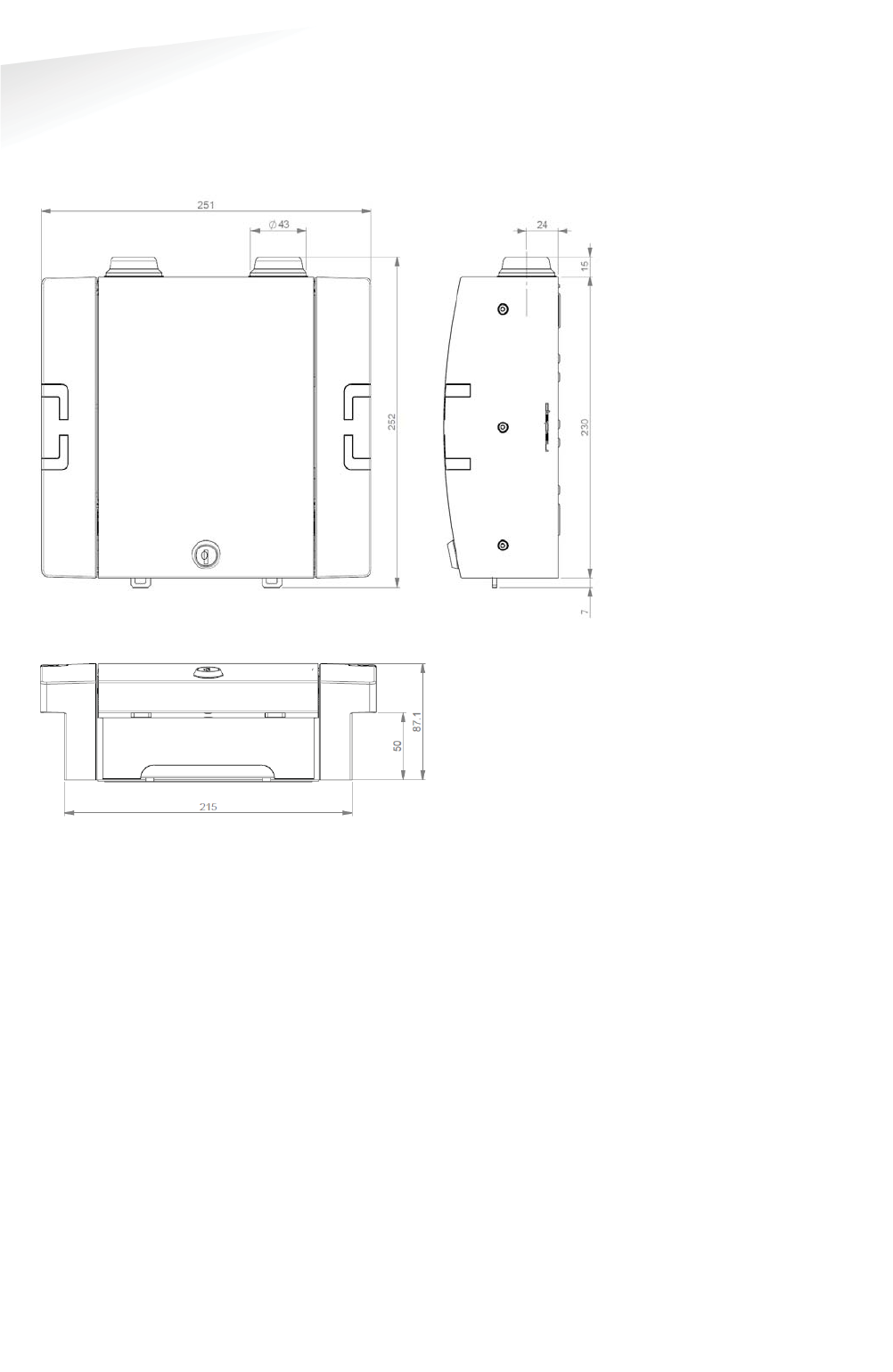
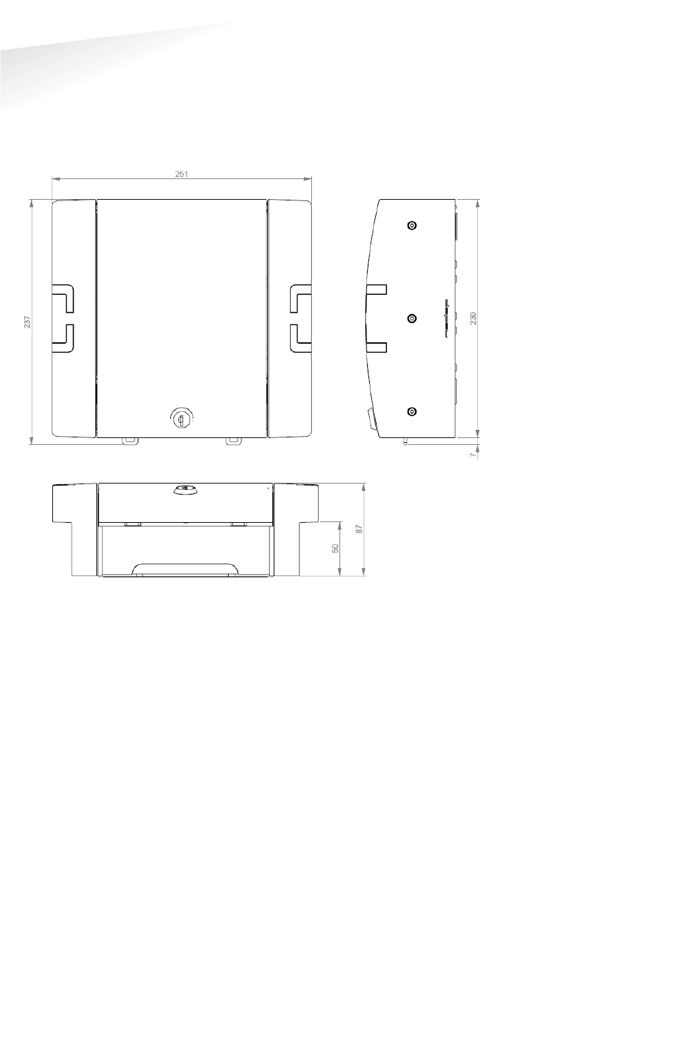
6.3.3 MOUNTING
The SENSIT Gateway can be installed virtually anywhere due to its IP65
weatherproof housing and embedded 3G wireless modem. The only requirements
are an AC mains power supply and that it should be installed within reach of the
SENSIT wireless network.
Figure 20: Gateway dimensions (mm)
SENSIT SYSTEM | MANUAL
Installation SENSIT Gateway
35/
111
Installation SENSIT Gatewa
y
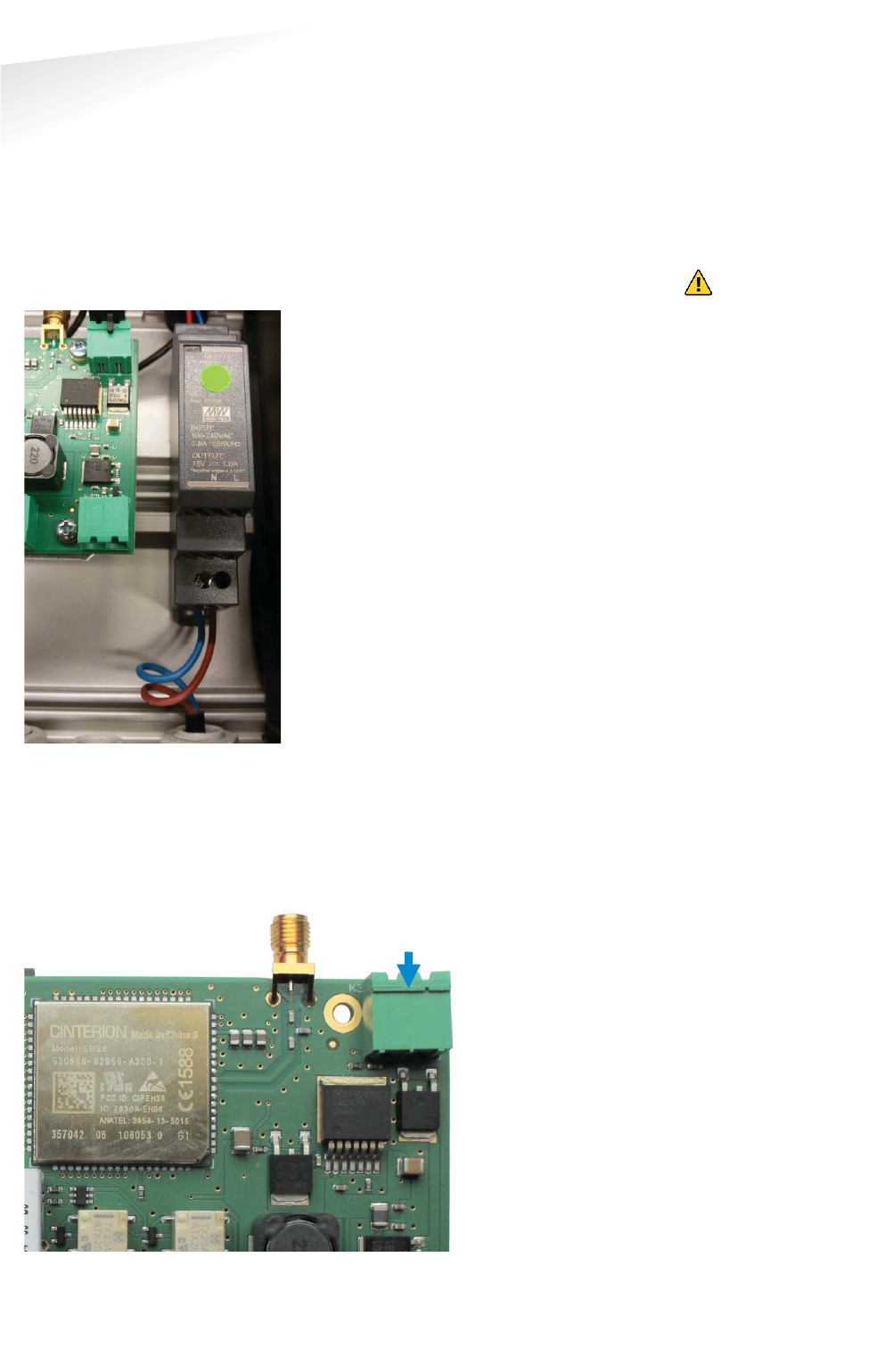
6.3.4 AC POWER SUPPLY
Connect an AC mains power supply to the Gateway. An earth wire isn’t needed due
to the double isolated (Safety class II) design of the power supply.
x Input requirements: 100 – 240VAC 50/60Hz
x Safety class II, UL 60950-1, Pass LPS (Limited power source).
x Power supply is UL 508 listed.
x Short circuit and overload protection.
x DC ok LED indicator.
x External disconnect device is needed.
Figure 21: Power supply connection
6.3.5 EXTERNAL SOLAR SET
It is also possible to connect an external 12V solar set to the SENSIT Gateway. The
external solar set should include beside the solar panel a (solar)battery charger and
a 12V battery. The set should be capable to source 120mA at 12VDC ( about 1.5W)
continuously.
Figure 22: Solar panel set connection.
112V
SSolar set
++
--
Disconnect power
before servicing
the device.
SENSIT SYSTEM | MANUAL
Installation SENSIT Gateway
36/
111
Insta
ll
ation SENSIT Gatewa
y
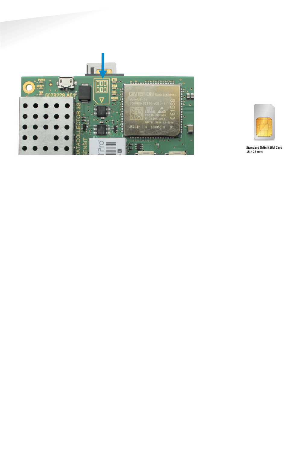
6.3.6 SIM CARD
Insert the standard (mini) SIM card at the top of the PCB as indicated.
Figure 24: SIM Card installation
6.3.7 ANTENNA
The SENSIT Gateway is featured with two antennas. One for communication with the
SENSIT nodes and the other is the mobile 3G antenna.
Note
Make sure your remove the
pin code from your SIM
-
card
e.g. by using your
mobile phone
.
Note
Example of standard (mini)
SIM card.
Figure
23: Mini SIM card
NNote
SIM card must be capable
to receive and transmit SMS
messages and to transfer
Data.
N
Note
Data usages is normally
less than 250MB per
month.
N
Note
Some mobile providers
disconnect an open TCP
connection when no data
transfer take place. The
Gateway expec
t an
uninterrupted TCP
connection.
N
Note
By default every 2 minutes
a small package is
transmitted by the SIS to
verify the open TCP
connection.
SENSIT SYSTEM | MANUAL
Gateway Configuration
37/
111
Gatewa
y
Con
f
iguratio
n
7 GATEWAY CONFIGURATION
TCP/IP CONFIGURATION
The standard SENSIT Gateway has an on-board TCP/IP communication. The TCP/IP
communication is used to send the messages from the SENSIT vehicle detections
sensors to the SENSIT Interface Software running on the server.
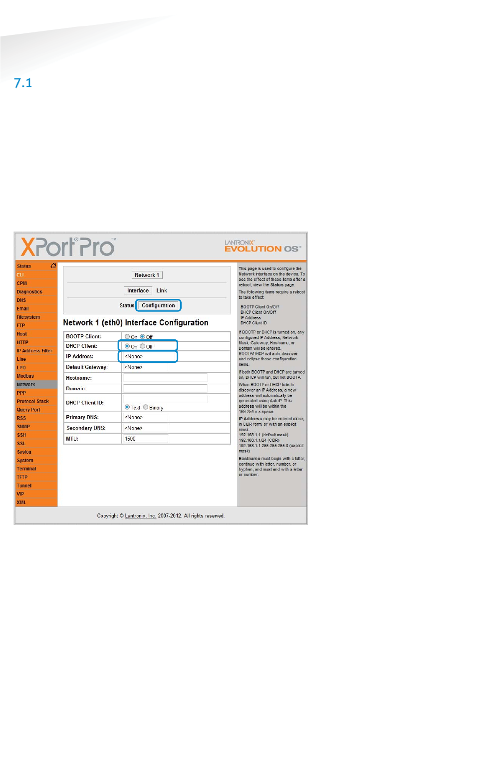
7.1.1 GATEWAY TCP/IP SETTINGS
The default fixed IP-address for the SENSIT Gateway is 192.168.1.2. Configuration
can be done using a web browser. By default there is no authentication needed, click
OK when the authentication popup appears. Nedap strongly recommends to change
the password. The fixed IP-address can be changed or set to DHCP, via at the left
Network and Configuration:
Figure 25: SENSIT Gateway TCP/IP Network configuration
Note
Use a shield RJ45 cable to
connect the Gateway.
Note
For safety reasons Nedap
strongly recommends to set
a password.
SENSIT SYSTEM | MANUAL
Gateway Configuration
38/
111
Gatewa
y
Con
f
iguratio
n
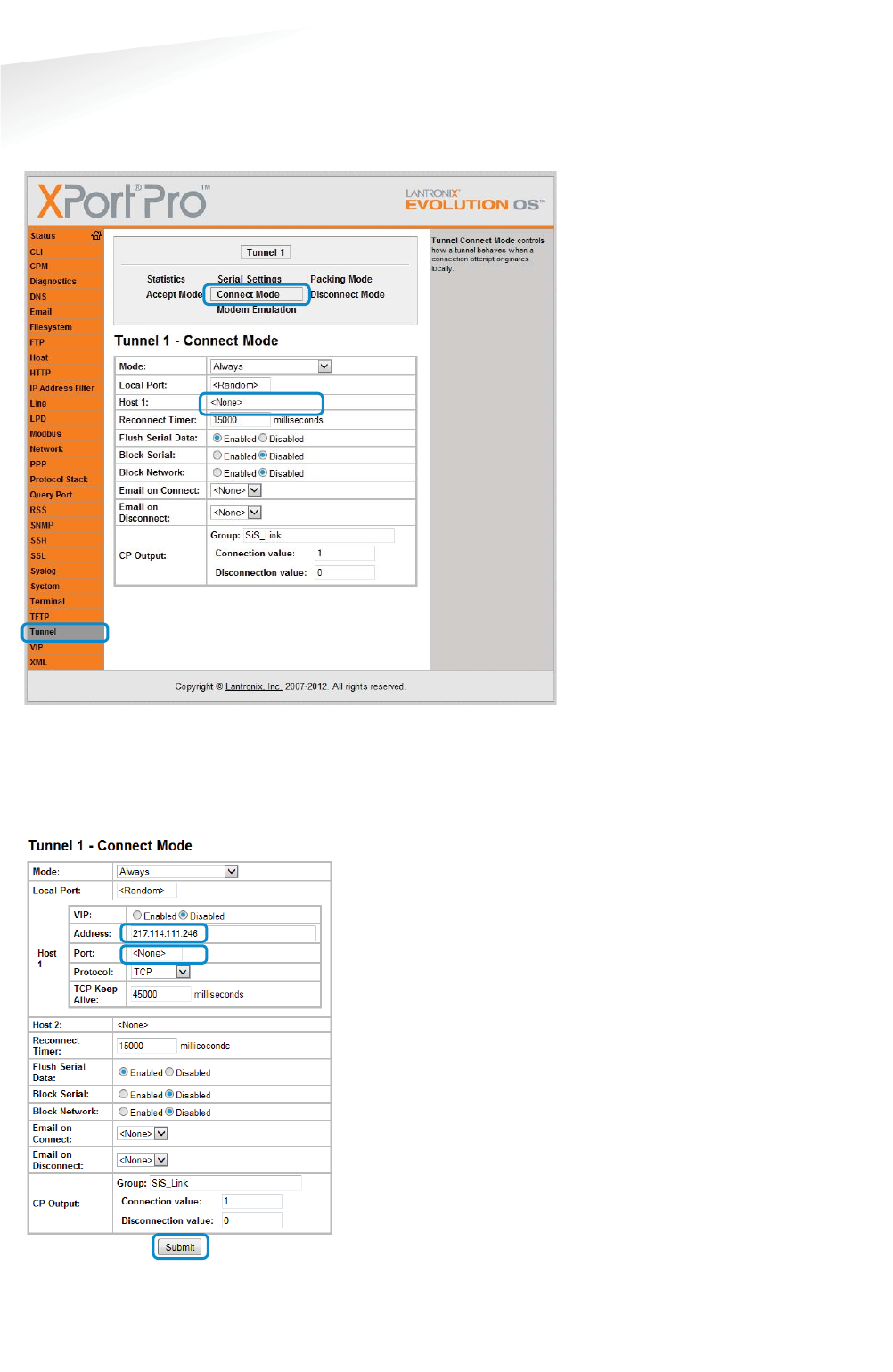
Next the SENSIT server settings should be configured. These settings are provided to
you when the SENSIT Interface Software (SIS) is installed on the server. These setting
you fill-in via at the left side Tunnel, Connect Mode and Host 1:
Figure 26: SENSIT Gateway TCP/IP Tunnel configuration
Fill in the (IP) Address: 217.114.111.246 is the default SIS server Address. In the
provide PDF you find the correct Port number. To use both settings, click the Submit
button.
Figure 27: SENSIT Gateway Host IP-address and port setting
Note
The
SENSIT Gateway
automatically
con
nect to
the server via internet.
Please make sure that the
IP
-address and assigned
port is open in your firewall.

SENSIT SYSTEM | MANUAL
Gateway Configuration
39/
111
Gatewa
y
Con
f
iguratio
n
3G CONFIGURATION
The 3G modem inside the SENSIT Gateway needs to be configured before it can
access the internet and connect to the SENSIT Interface Software at the server. This
is done by sending 2 SMS text messages to the SENSIT Gateway. Any GSM cell phone
can be used to send these configuration text messages.
7.2.1 PROFILE:
First the APN settings should be configured. These settings depend upon the mobile
network provider. The settings are sent in a SMS message using the following format:
P
PROFILE:APN=<apn>;APNLOGIN=<login>;APNPASSWORD=<pwd>;DNS=<dns>;
Where: <apn> APN (Access Point Name)
<login> User name
<pwd> Password
<dns> DNS (Domain Name Server)
Example:
PROFILE:APN=gprsinternet;APNLOGIN=gprs;APNPASSWORD=;DNS=;
Next the SENSIT server settings should be configured. These settings are provided to
you when the SENSIT Interface Software (SIS) is installed on the server. The settings
are sent in a SMS message using the following format:
PROFILE:HOSTNAME=<server>;PORT=<port>;SSL=<ssl>;
Where: <server> SENSIT server hostname or ip-address
<port> Port number
<ssl> true / false depending if SSL security is
used.
Example:
PROFILE:HOSTNAME=217.114.111.246;PORT=10000;SSL=false;
7.2.2 INFO:
To check the SIM card or the verify the mobile phone number a INFO SMS command
returns some detail information. The returned information is the IMEI number, the
IMSI number, mobile provider details, the signal quality and the software version.
Example:
INFO:
Note
Make sure the SMS does not
get longer than the default
message size of 160
characters.
Note
The SENSIT Gateway will
send a SMS back to the
phone number you send
the SMS with. All current
settings are transmitted
after sending a SMS
message.
SENSIT SYSTEM | MANUAL
Gateway Configuration
40/
111
Gatewa
y
Con
f
iguratio
n
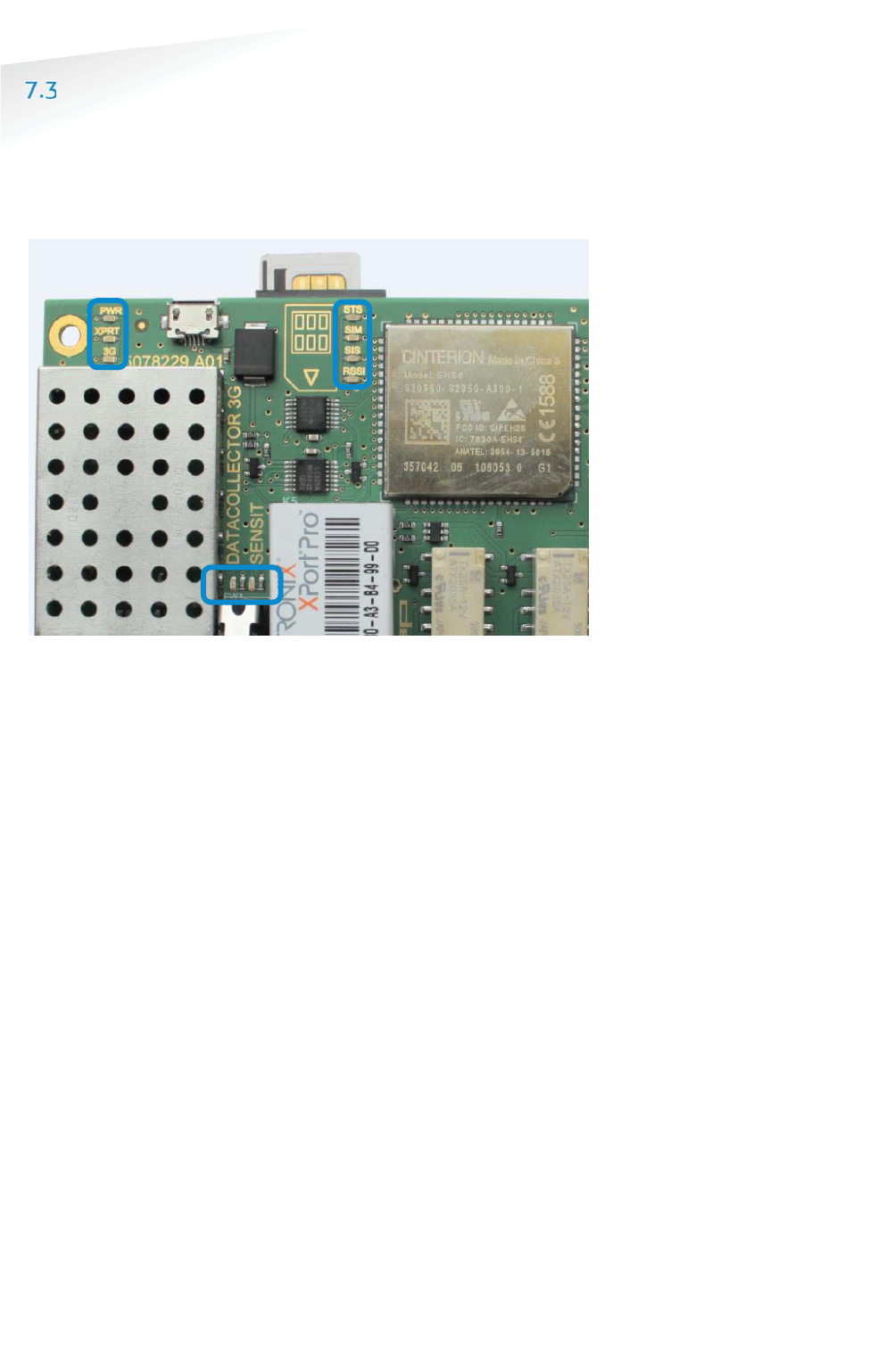
SENSIT GATEWAY LED BEHAVIOR
At the SENSIT Gateway there is a more detailed LED feedback implemented. At the
left top corner, the power and general connection feedback and at the right of this
the 3G modem feedback LEDs. The WSN LED indications can be found just above the
tamper switch.
Figure 28: SENSIT Gateway LED feedback
7.3.1 PWR (POWER) LED
The first LED at the top left corner is the power (PWR) LED, this indicates if the
SENSIT Gateway electronics is powered. The LED behavior is described below:
x P
Permanently off
The electronics isn’t powered.
x
Permanently on
The electronics is powered.
7.3.2 XPRT (XPORT) LED
The second LED at the top left corner is the XPORT (XPRT) or Ethernet LED, this
indicates if the SENSIT Gateway is connected via Ethernet to the SIS. The LED
behavior is described below:
x
Permanently off
Not connected with the SIS via Ethernet.
x
Permanently on
Connected with the SIS via Ethernet.
7.3.3 3G LED
The second LED at the top left corner is the 3G LED, this indicates if SENSIT Gateway
is connected via the 3G mobile network to the SIS. The LED behavior is described
below:
x
Permanently off
Not connected with the SIS via 3G.
x
Permanently on
Connected with the SIS via 3G.
Note
Closing the tamper switch
will disable the feedback
LED’s

SENSIT SYSTEM | MANUAL
Gateway Configuration
41/
111
Gatewa
y
Con
f
iguratio
n
7.3.4 STS (3G STATUS) LED
The first feedback LED of the 3G modem LEDs is the status (STS) LED of the 3G
modem. This LED has the following behavior::
x P
Permanently off
3G Modem is not running.
x
500 ms on / 500ms off
3G Modem firmware is starting.
x
Permanently on
Firmware of the 3G modem is up and running.
7.3.5 SIM LED
The second feedback LED of the 3G modem LEDs is the SIM-card LED. This LED has
the following behavior::
x
Permanently off
No SIM card inserted or detected.
x
500 ms on / 500ms off
SIM card is inserted and busy to unlock or the SIM card is locked.
x
Permanently on
Sim card is unlocked.
7.3.6 SIS LED
The second feedback LED of the 3G modem LEDs is the SENSIT Interface Server (SIS)
LED and shows the connection to the (SIS) Server. This LED has the following
behavior::
x
Permanently off
An not unlocked SIM-card or searching for a (3G) network.
x
500 ms on / 500ms off
Registered to a (3G) network.
x
Permanently on
Port is opened and connected to the (SIS) server.
7.3.7 RSSI LED
The forth feedback LED of the 3G modem LEDs is the RSSI (Receive Signal Strength
Indication) LED and shows the signal strength of the 3G base station. This LED has
the following behavior::
x
Permanently off
No (3G) network or RSSI level is below -100dBm.
x
500 ms on / 500ms off
RSSI level is between -100 dBm and -70dBm.
x
Permanently on
RSSI level is above -70dBm.
Note
Closing the tamper switch
will disable the feedback
LED’s
SENSIT SYSTEM | MANUAL
Gateway Configuration
42/
111
Gatewa
y
Con
f
iguratio
n
7.3.8 WSN LED INDICATIONS
The SENSIT Gateway is featured with two LEDs indicating the WSN (Wireless SENSIT
Network) operation. These LEDs can be found just above the tamper switch, see
Figure 28: SENSIT Gateway LED feedback. The table below describes the function of
the WSN LEDs.
SSENSIT GGateway LLED indication.
Green (D1) LED indicating the presence of
active Relay Nodes in
the wireless SENSIT network.
Red (D2)
LED indicating the
activity of the SENSIT Gateway, the
Gateway is stated and maintaining the wireless
SENSIT network.
Table 1: LED indications
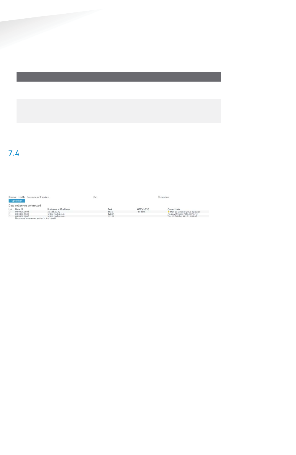
VERIFY COMMUNICATION
Via the SENSIT Interface Software (SIS) a more detailed description can be found in
chapter 17.1. After choosing: Detection Î Gateway choice at the left side of the
screen. The powered and to the internet connected SENSIT Gateways, should show
up automatically
in the Gateways connected list.
Figure 29: Verify connected SENSIT Gateways at the SIS

SENSIT SYSTEM | MANUAL
Mounting The SENSIT BACKUP Battery
43/
111
M
ountin
g
The SENSIT BA
C
KU
P
Batter
y
8 MOUNTING THE SENSIT BACKUP BATTERY
SAFETY PRECAUTIONS
The following safety precautions should be observed during normal use, service and
repair.
x The SENSIT backup battery may only be installed and serviced by qualified
service personnel.
x Disconnect the power supply of the SENSIT Gateway before removing or
installing the SENSIT backup battery.
x To be sure of safety, do not modify or add anything to the SENSIT backup
battery other than mentioned in this manual or indicated by NEDAP N.V
INSTALLATION CONDITIONS
The installation recommendation is based on the following environmental
conditions;
x Dry weather conditions.
REQUIRED INSTALLATION MATERIALS
The following would be required for mounting of the SENSIT backup battery. In case
of wall mounting.
x Special Equipment: Ladder, Bucket-truck or an aerial platform
x Power drill
x Set screw driver
x Wall plugs or anchors including screws
The needed materials for pole mounting are described at chapter 9.
MOUNTING
The SENSIT backup battery must be mounted in the close vicinity of Gateway. Often
it is installed back-to-back on a pole. Similar as the Gateway it can be installed
virtually anywhere due to its IP65 weatherproof housing.
SENSIT SYSTEM | MANUAL
Mounting The SENSIT BACKUP Battery
44/
111
M
ounting The SENSIT BACKUP Batter
y
8.4.1 DIMENSIONS
The SENSIT back up battery is installed inside a similar housing as the Gateway. Only
without the antennas and with a few less cable glands. The dimensions can be found
below.
Figure 30: Back up battery dimensions (mm)
SENSIT SYSTEM | MANUAL
Mounting The SENSIT BACKUP Battery
45/
111
M
ounting The SENSIT BACKUP Batter
y
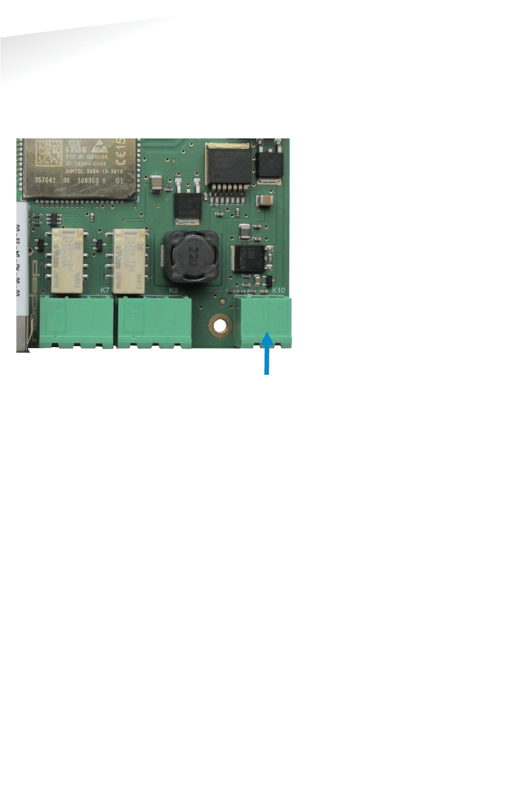
8.4.2 CONNECTION TO THE GATEWAY
The SENSIT backup battery contains a lead-acid battery, a fuse and a connection wire
that can directly be connected to the SENSIT Gateway. The SENSIT Gateway contains
the circuit to charge the lead-acid battery when connected to mains. The figure
below indicates the right connection and polarity to connect the SENSIT backup
battery.
Figure 31: SENSIT backup battery connection
++112VDC
BBack up
BBattery
++
--
SENSIT SYSTEM | MANUAL
Pole mounting set
46/
111
Pole mountin
g
se
t
9 POLE MOUNTING SET
The Backup Battery and the SENSIT Gateway can be equipped with a pole mounting
set. This set includes all mounting materials to mount a SENSIT Gateway or a Battery
Pack housing to a round- (max. diameter is 300mm) or square pole (max. 250mm).
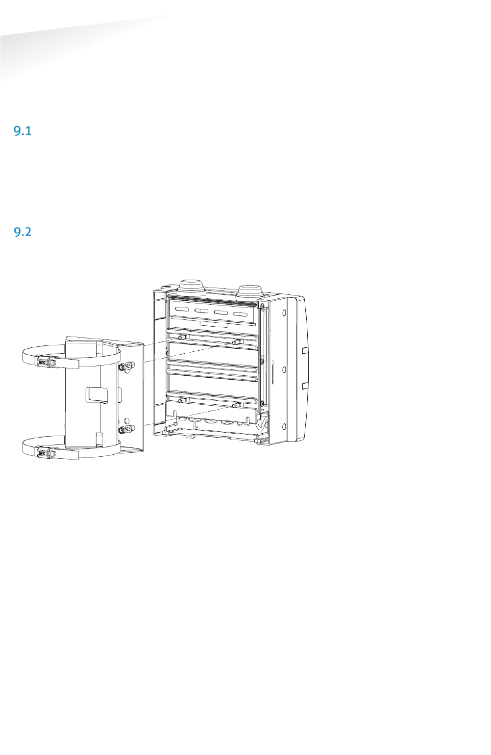
REQUIRED INSTALLATION MATERIALS
The following would be required for mounting the Pole mount set to a SENSIT
Gateway or a Battery Pack housing and finally to a pole.
x Special Equipment: Ladder, Bucket-truck or an aerial platform
x Wrench: size 10
x Cutter: for stainless steel strap
x Set screw driver
MOUNTING
The pole mount set includes all mounting materials to mount a SENSIT Gateway or a
Battery Pack housing to a pole. The bracket can be bolted to the SENSIT Gateway or
Battery Pack housing, see figure below for more details.
Figure 32: Pole Mount set installation
Furthermore the pole mount set includes, the needed bolts, washers and nuts (4x)
and an adjustable clamp set, to strap the housing to the pole.
SENSIT SYSTEM | MANUAL
Mounting The Relay Node 2G
47/
111
M
ounting The Rela
y
Node 2
G
10 MOUNTING THE RELAY NODE 2G
SAFETY PRECAUTIONS
The following safety precautions should be observed during normal use, service and
repair:
x The Relay Node only be installed and serviced by qualified service
personnel.
x To be sure of safety, do not modify or add anything to the SENSIT Relay
Node 2G other than mentioned in this manual or indicated by Nedap N.V.
IC AND FCC ID
FCC ID: CGDRELAY and IC: 1444A-RELAY
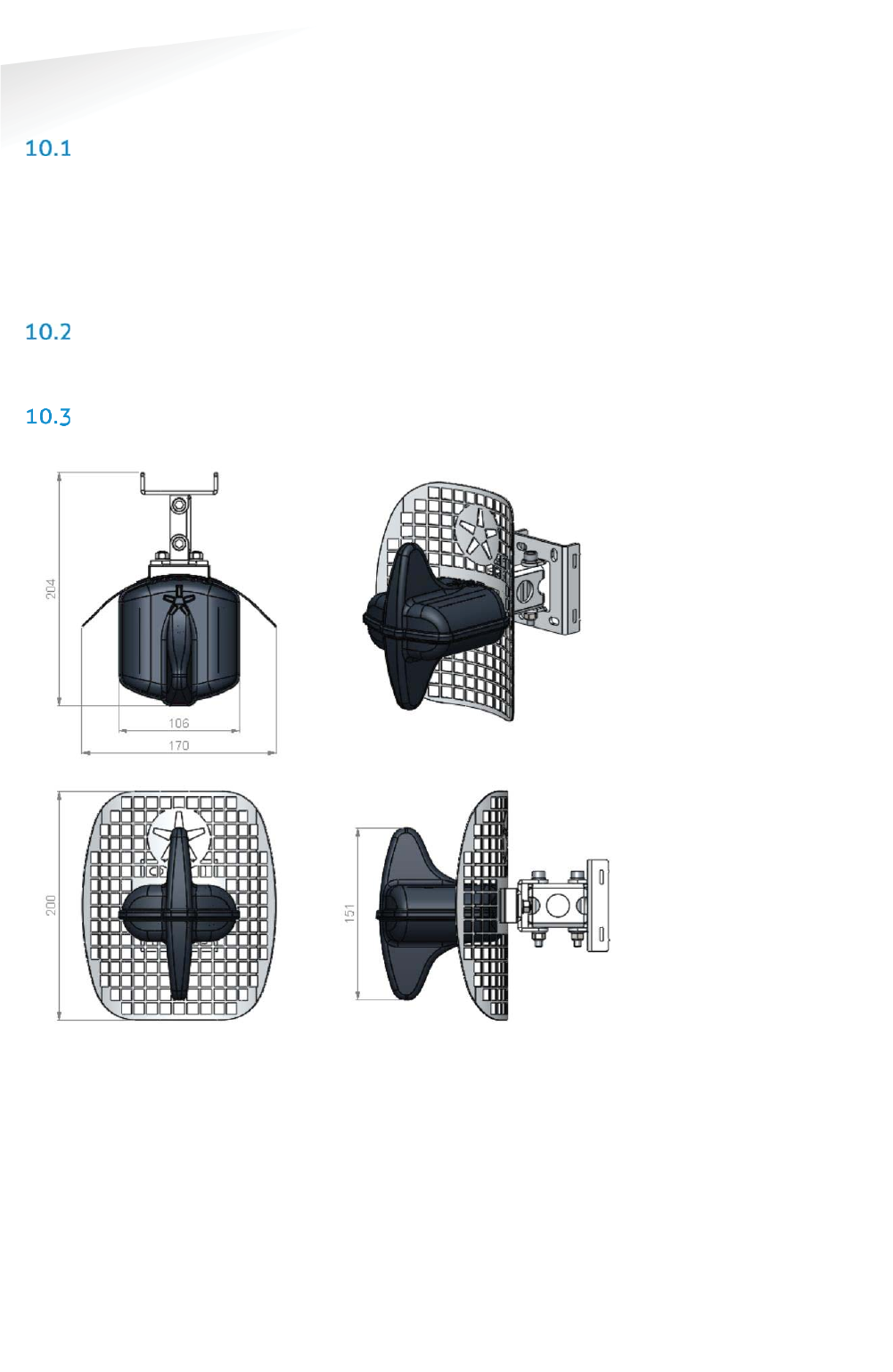
DIMENSIONS
See Figure 33 for the dimensions (in mm) of the Relay Node 2G unit.
Figure 33: Dimensions Relay Node 2G (mm)

SENSIT SYSTEM | MANUAL
Mounting The Relay Node 2G
48/
111
M
ounting The Rela
y
Node 2
G
INSTALLATION CONDITIONS
The installation recommendation is based on the following environmental
conditions;
x Dry weather conditions.
REQUIRED INSTALLATION MATERIALS
The following would be required for mounting of the SENSIT Relay Node 2G.
x Special Equipment: Ladder, Bucket-truck or an aerial platform
x TORX screw driver: T20
x Allen key: no. 5
x Wrench: size 10
INSTALLATION PROCEDURE
Below the mounting procedure for the Relay Node 2G. The Relay Node 2G features
visual status feedback using two LED indicators: a green and a red LED.
SSENSIT Relay Node 2G mounting procedure
SStep 1:
Mounting
Mount the reflector and top of the
housing on the pole or wall. With the
Nedap asterisk at the top. The Relay
Node 2G can also be mounted without
the reflector for an omni-directional
radiation pattern.
SStep 2:
Power the
Relay Node
Remove the isolation tabs, to power up
the Relay Node.
SStep 3:
Verify start-
up
Green LED starts blinking fast (duration:
15 sec.), indicating that battery power
has been connected correctly.
SStep 4:
WSN search
Red LED starts to blink slowly. This
indicates that the Relay Node didn’t
found an active WSN (wireless SENSIT
Network) yet. It is searching for a WSN.
SStep 5:
WSN found
Green LED starts slow blinking and red
LED is turned off. This indicates that a
WSN has been found.
SStep 6:
Final
installation
Now the Relay Node electronics can be
installed at the pole or wall with a TORX
(T20) screw driver.
Note
When segmentation is
needed, please use the
Configuration Tool and set
the right segment.
Note
The Green and Red
feedback LED’s are located
in the
blue circle.
Note
After 15 minutes LED
feedback is turned off, to
save battery power.
Note
After 1 minute the LED
feedback is turned off, to
save battery power.
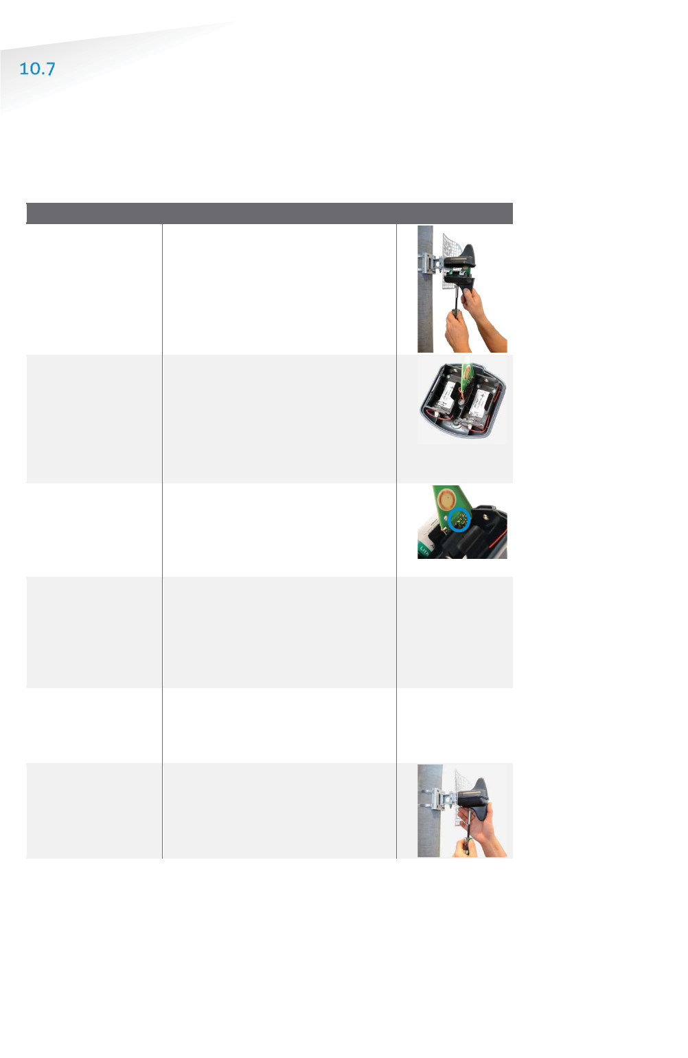
SENSIT SYSTEM | MANUAL
Mounting The Relay Node 2G
49/
111
M
ounting The Rela
y
Node 2
G
BATTERY REPLACEMENT
When the battery life of the Relay Node 2G fails after specified lifetime, the
batteries can be changed make sure you use the right batteries:
D-cell Lithium Thionyl Chloride batteries (Li-SOCl2) 3.6V, recommended types are:
x SAFT | LS 33600
x XENO | XL-205F
SSENSIT Relay Node 2G battery replacement
SStep 1:
Opening the
housing
Open the Relay Node 2G housing by
unscrewing the TORX, T20 screw.
SStep 2:
Replace the
batteries
Remove the old batteries and
dispose them in the correct manner.
Place the new 3.6V Lithium (Li-
SOCL2) batteries (see suggested
types above) and make sure the
polarity is correct, as indicated.
SStep 3:
Verify start-up
Green LED starts blinking fast
(duration: 15 sec.), indicating that
battery power has been connected
correctly.
SStep 4:
WSN search
Red LED starts to blink slowly. This
indicates that the Relay Node didn’t
found an active WSN (wireless
SENSIT Network) yet. It is searching
for a WSN.
SStep 5:
WSN found
Green LED starts slow blinking and
red LED is turned off.
This indicates
that a WSN has been found.
SStep 6:
Final installation
Now the Relay Node electronics can
be installed at the pole or wall with a
TORX (T20) screw driver.
Note
Previous segmentation is
stored, when the same
segment still applies you
don’t need to segment the
Relay Node 2G again.
Note
The Green and Red
feedback LED’s are located
in the
blue circle.
Note
After 15 minutes LED
feedback is turned off, to
save battery power.
Note
After 1 minute the LED
feedback is turned off, to
save battery power.
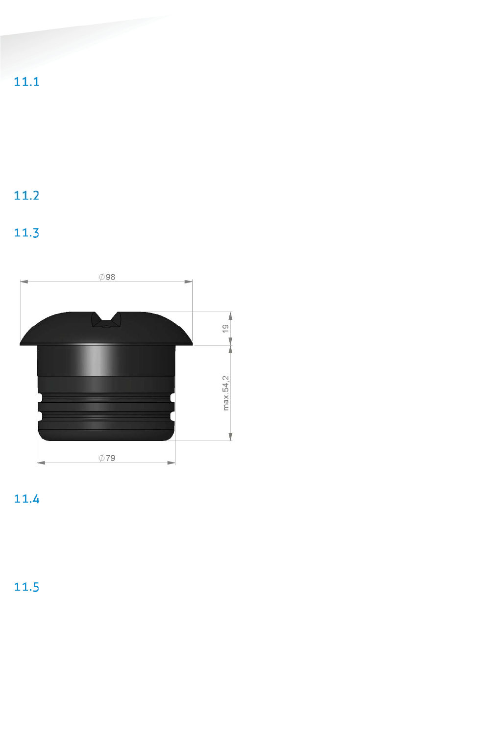
SENSIT SYSTEM | MANUAL
Mounting The SENSIT IR
50/
111
M
ountin
g
The
SE
NS
IT I
R
11 MOUNTING THE SENSIT IR
SAFETY PRECAUTIONS
The following safety precautions should be observed during normal use, service and
repair:
x The SENSIT IR may only be installed and serviced by qualified service
personnel.
x To be sure of safety, do not modify or add anything to the SENSIT IR other
than mentioned in this manual or indicated by NEDAP N.V.
IC AND FCC ID
FCC ID: CGDSENSIT and IC: 1444A-SENSIT
DIMENSIONS
The SENSIT IR is designed for mounting into the floor of a parking space. See Figure
34 for the dimensions of the unit in mm.
Figure 34: Dimensions SENSIT IR (mm).
INSTALLATION CONDITIONS
The installation recommendation is based on the following environmental
conditions;
x Ambient temperature between 5 to 40 °C (41 to 104 °F0
x Dry weather conditions
x Surface based on concrete, asphalt or pavement
REQUIRED INSTALLATION MATERIALS
The following would be required for mounting of the SENSIT IR.
x Equipment: Automatic core drill
x Drill size: Dimensions Ø 85 mm (3.35 in)
x Drill depth: 55 mm (2.16 in)
x Filler material: Liquid rapid mortar
x Required amount per sensor: Approx 100 ml
We have good results with the rapid mortar TM 5R. See appendix B for
specifications. Ensure to follow the guidelines and instructions as outlined on the
filler material.
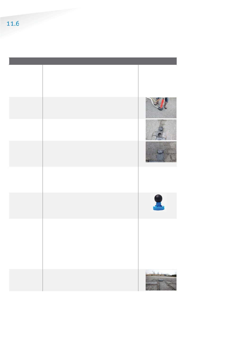
SENSIT SYSTEM | MANUAL
Mounting The SENSIT IR
51/
111
M
ountin
g
The SENSIT I
R
INSTALLATION PROCEDURE
Below the mounting procedure for the SENSIT sensor with and without the
Configuration Tool.
11.6.1 WITHOUT THE CONFIGURATION TOOL
SSENSIT sensor mounting procedure
SStep 1:
Preparation
Indicate on
the closed parking lot where the
SENSIT sensor should be mounted. Distribute
the SENSIT sensors over the parking lot and
write down the correct ID numbers on your
installation plan.
Step 2:
Drilling
Drill a hole of Ø 85 mm [3.35 in]
and at least
55 mm [2.16 in] deep into the center
of the
parking bay
SStep 3:
Gluing
Apply the right amount of filler and pour into
the hole.
SStep 4:
Mounting
Double-check the node ID number and the
parking bay on the installation plan and
place the SENSIT sensor into the hole.
SStep 5:
Cleaning-
up
After mounting the SENSIT sensors in all
parking bays or a selection of parking bays.
Clean up the parking bays and remove all
(metal) tools and objects.
SStep 6:
Activating
All SENSIT sensors are set into
transport/stock mode during shipment. After
installation all mounted SENSIT sensors must
be swept with the reset magnet.
SStep 7:
Calibrating
After installation the SENSIT sensor
must be
calibrated. Ensure that the parking space is
empty and that there is no car parked on top
of the sensor or on neighboring parking bays.
SENSIT sensors can be calibrated via the
SENIST Interface Software (SIS). See chapter
17.8.6 for more information about
calibration.
SStep 8:
Glue curing
Leave the filler harden for 8 hours before
vehicles are allowed in the parking space
again.
Note
Take attention that you
fixate the SENSIT sensor
during the curing time
otherwise the sensor will
start to float.
Note
Once out of the
transport/stock mode the
battery lifetime starts to
count
.
Note
When the SENSIT sensors
are not calibrated they
hardly send any messages.
This is due to the fact that
there are no events
generated because the
magnetic thresholds are not
crossed.
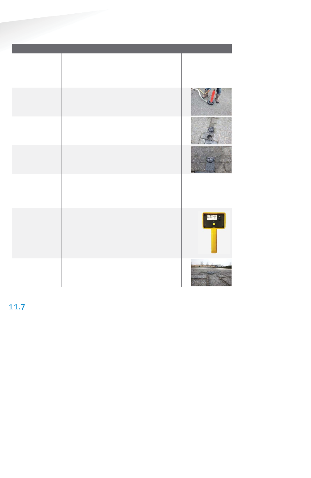
SENSIT SYSTEM | MANUAL
Mounting The SENSIT IR
52/
111
M
ountin
g
The SENSIT I
R
11.6.2 WITH THE CONFIGURATION TOOL
SSENSIT sensor mounting procedure
SStep 1:
Preparation
Indicate on the closed parking lot where
the SENSIT sensor should be mounted.
Distribute the SENSIT sensors over the
parking according the installation plan.
Step 2:
Drilling
Drill a hole of Ø 85 mm [3.35 in] and at
least 55 mm [2.16 in]
deep into the center
of the parking bay
SStep 3:
Gluing
Apply the right amount of filler and pour
into the hole.
SStep 4:
Mounting
Place
the SENSIT sensor into the hole and
make sure it doesn’t start to float.
SStep 5:
Cleaning-up
After mounting the SENSIT sensors in all
parking bays or a selection of parking bays.
Clean up the parking bays and remove all
(metal) tools and objects.
SStep 6:
Activating
Segmentation
Calibration
Use the Configuration Tool: Activate,
perform the segmentation according the
installation plan
and calibrate the SENSIT
sensor.
SStep 77::
Glue curing
Leave the filler harden for 8 hours before
vehicles are allowed in the parking space
again.
REPLACEMENT
When the battery life of the SENSIT IR fails after specified lifetime, we advise to
replace the unit completely. The SENSIT IR is fully sealed and for outdoor use,
therefore batteries cannot be replaced.
Drill out the old SENSIT IR and complete the mounting procedure as describe in the
previous paragraph.
Ensure to note the node ID number of the SENSIT IR to the parking bay. Update the
parking bay configuration list in the SIS software to ensure the new sensor is linked
to the right parking bay.
Note
Take attention that you
fixate
the SENSIT sensor
during the curing time
otherwise the sensor will
start to float.
Note
Once out of the
transport/stock mode the
battery lifetime starts to
count
.
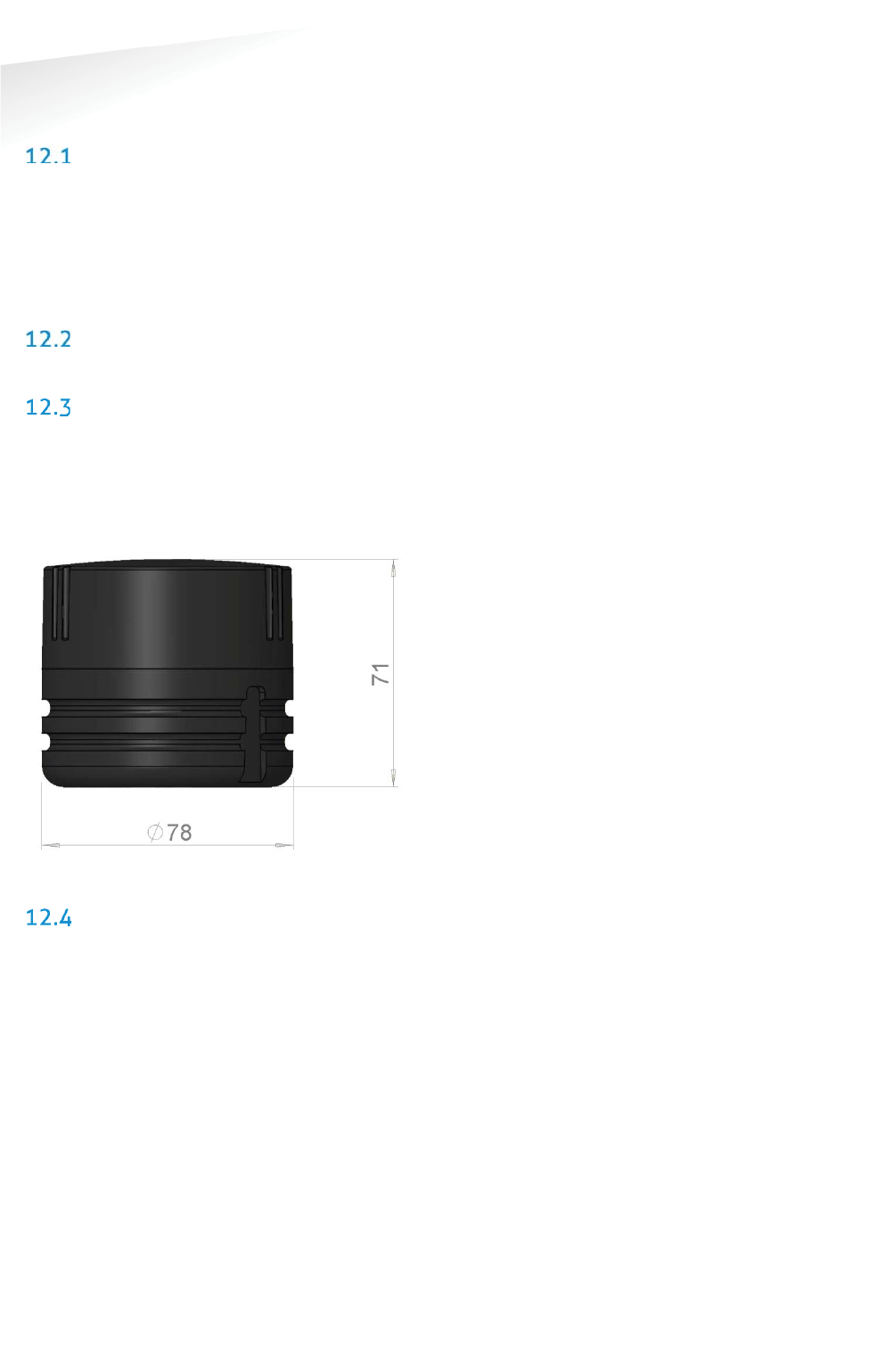
SENSIT SYSTEM | MANUAL
mounting The SENSIT IR Flush Mount
53/
111
mountin
g
The SENSIT IR Flush Mount
12 MOUNTING THE SENSIT IR FLUSH MOUNT
SAFETY PRECAUTIONS
The following safety precautions should be observed during normal use, service and
repair.
x The SENSIT Surface Mount may only be installed and serviced by qualified
service personnel.
x To be sure of safety, do not modify or add anything to the SENSIT Surface
Mount other than mentioned in this manual or indicated by NEDAP N.V.
IC AND FCC ID
FCC ID: CGDSENSIT and IC: 1444A-SENSIT
DIMENSIONS
The SENSIT Flush Mount is designed for full mounting into the floor of a parking
space. As the unit is fully flush with the road surface the unit is snow plough
resistant. The SENSIT Flush Mount is only featured with magnetic detection. See
Figure 35 for the dimensions of the unit in mm. The top of the SENSIT Flush Mount
is laser engraved with the node ID number.
Figure 35: Dimensions SENSIT Flush mount (mm).
INSTALLATION CONDITIONS
The installation recommendation is based on the following environmental
conditions;
x Ambient temperature between 5 to 40 °C [41 to 104 °F]
x Dry weather conditions
x Surface based on concrete, asphalt or pavement
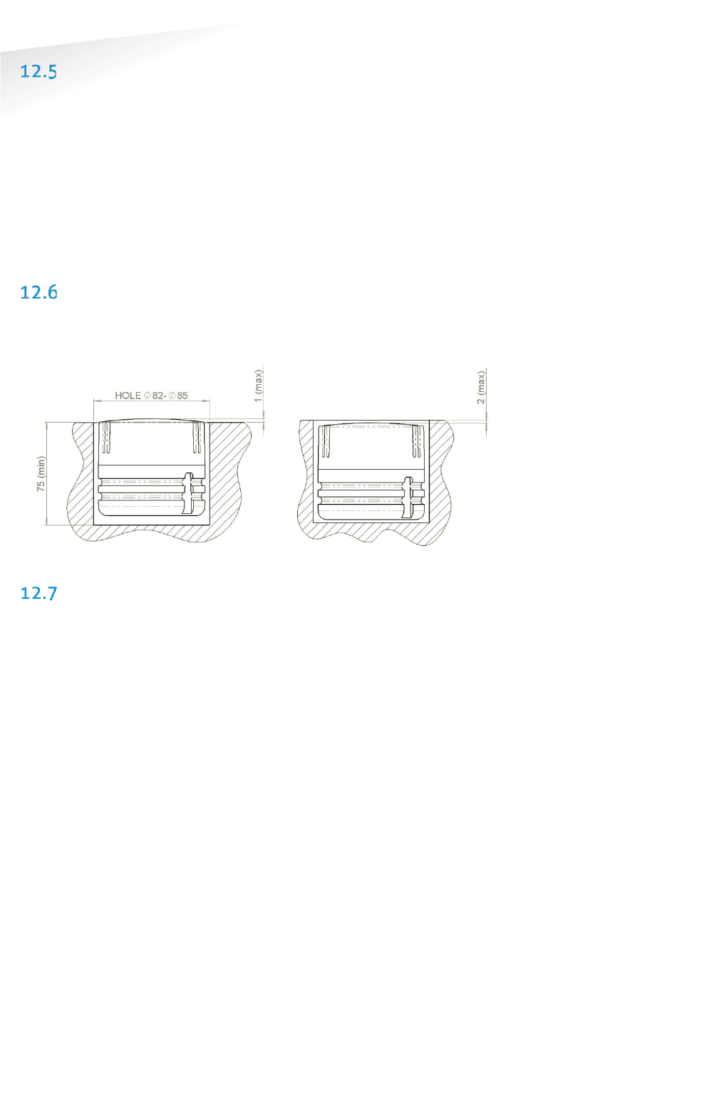
SENSIT SYSTEM | MANUAL
mounting The SENSIT IR Flush Mount
54/
111
mountin
g
The SENSIT IR Flush Mount
INSTALLATION MATERIAL
The following would be required for mounting of the SENSIT FLUSH MOUNT.
x Equipment: Automatic core drill
x Drill size: Dimensions Ø 85 mm (3.35 in)
x Drill depth: 75 mm (2.95 in)
x Filler material: Liquid concrete mortar
x Required amount per sensor: Approx. 100 ml
We have good results with the rapid mortar TM 5R. See appendix B for
specifications. Ensure to follow the guidelines and instructions as outlined on the
filler material.
INSTALLATION PROCESS
Installation process as described in paragraph 11.6, however with above mentioned
drilling depth. See figure below for more details about the mounting depth of the
SENSIT Flush Mount, dimensions in mm.
Figure 36: Mounting depth SENSIT Flush mount (mm).
REPLACEMENT
When the battery life of the SENSIT Flush Mount fails after specified life time, we
advise to replace the unit completely. The SENSIT Flush Mount is fully sealed,
therefore batteries cannot be replaced. Drill out the old SENSIT Flush Mount and
complete the mounting procedure as described in paragraph 11.6.
Ensure to note the node ID number of the SENSIT IR to the parking bay. Update the
parking bay configuration list in the SIS software to ensure the new sensor is linked
to the right parking bay.
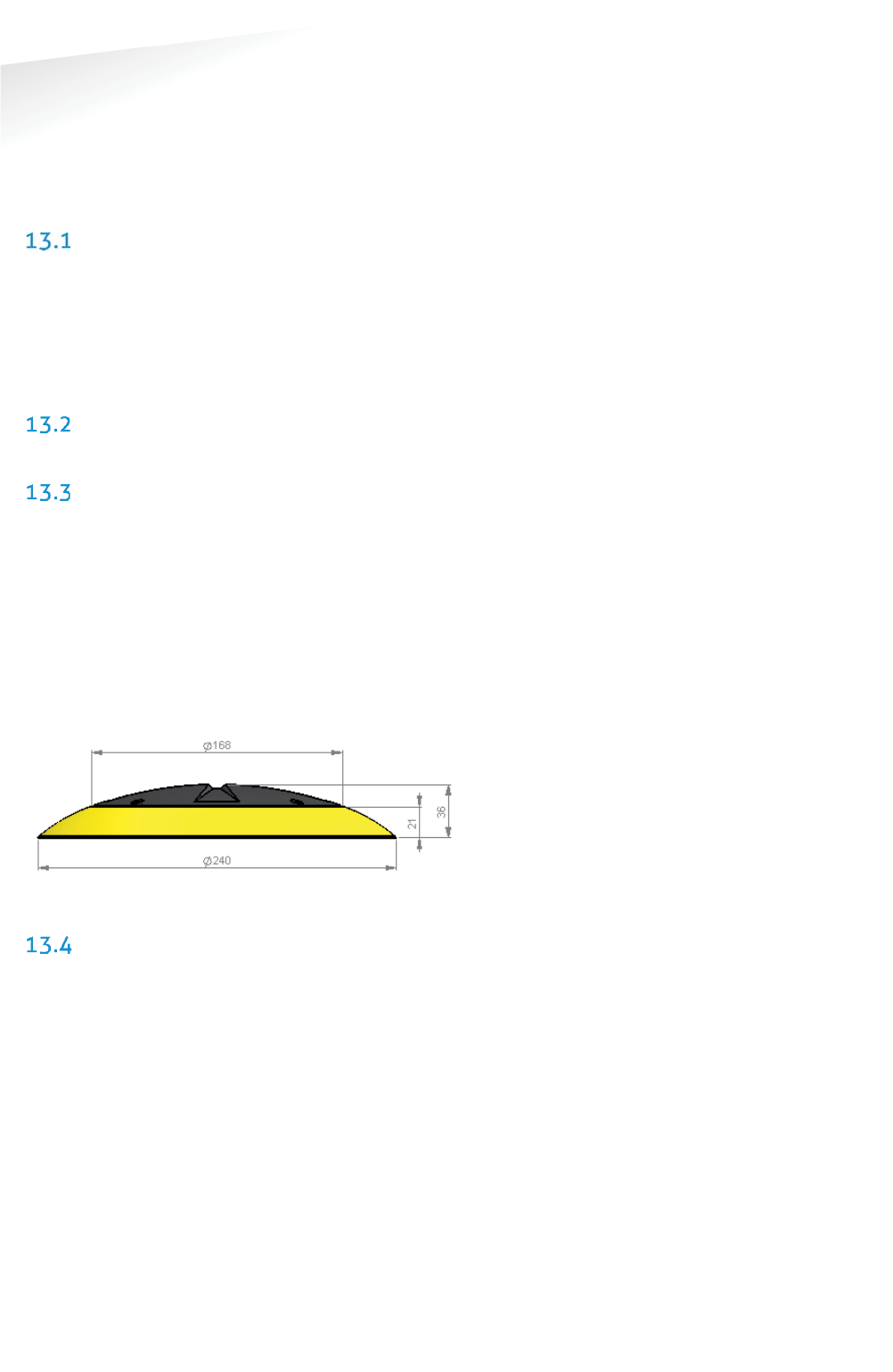
SENSIT SYSTEM | MANUAL
Mounting The SENSIT Surface Mount
55/
111
M
ountin
g
The SENSIT Sur
f
ace Moun
t
13 MOUNTING THE SENSIT SURFACE MOUNT
The SENSIT Surface Mount is designed for installations where the sensors cannot be
drilled into the parking space e.g. multi storey car parks and rooftop car parks or
existing car parks.
SAFETY PRECAUTIONS
The following safety precautions should be observed during normal use, service and
repair.
x The SENSIT Surface Mount may only be installed and serviced by qualified
service personnel.
x To be sure of safety, do not modify or add anything to the SENSIT Surface
Mount other than mentioned in this manual or indicated by NEDAP N.V.
IC AND FCC ID
FCC ID: CGDSENSITSM and IC: 1444A-SENSITSM
DIMENSIONS
The SENSIT Surface Mount can easily be glued onto the surface of a parking space.
The unit consists of two components;
x Sensor core; the black core is the vehicle detection sensor. This unit can be
replaced after end of battery life.
x Mounting ring; the mounting ring allows easy installation onto the surface of
a parking space.
See Figure 37 for the dimensions of the unit, dimensions in mm. The top of the
SENSIT Surface Mount is laser engraved with the node ID number.
Figure 37: Dimensions SENSIT Surface Mount (mm).
REQUIRED INSTALLATION MATERIALS
The following would be required for mounting of the SENSIT FLUSH MOUNT.
x Equipment: Pneumatic kit dispenser
x Filler material: MSP or PU glue
x Required amount per sensor: Approx. 150 ml
Note
See Appendix
20B and
20C
for more information about
the recommended MSP or
PU glue.
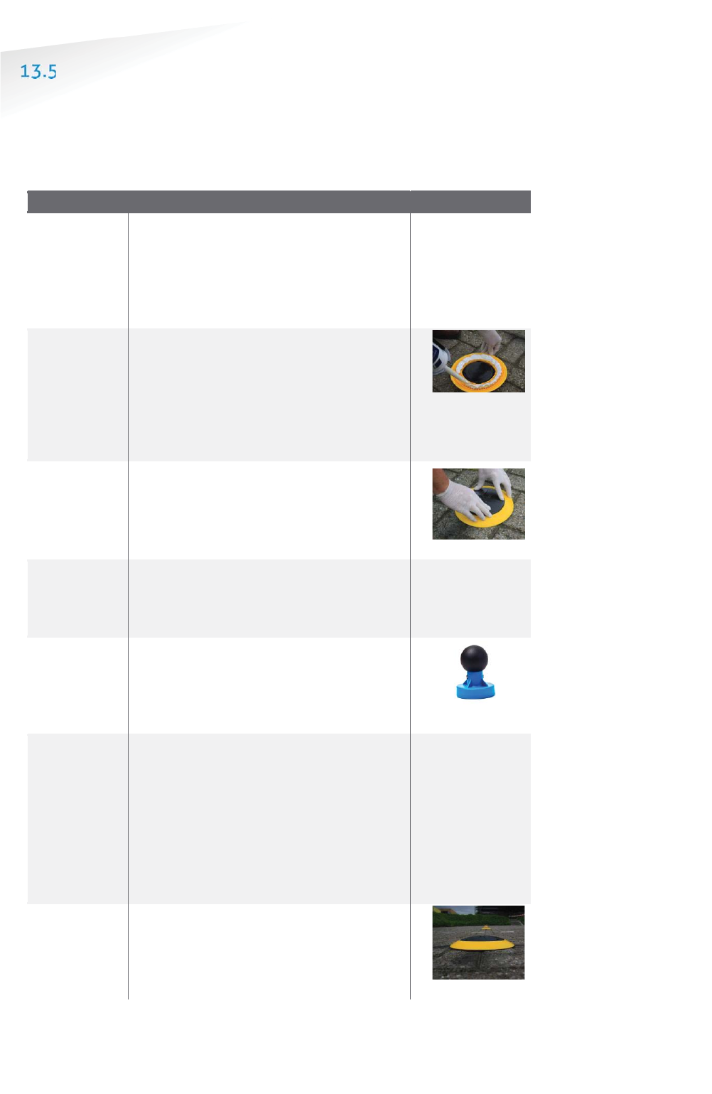
SENSIT SYSTEM | MANUAL
Mounting The SENSIT Surface Mount
56/1
11
M
ountin
g
The SENSIT Sur
f
ace Moun
t
INSTALLATION PROCESS
Follow the recommended installation procedure for the SENSIT Surface Mount as
described below. In the chapters below you can find the installation procedure with
and without the Configuration Tool.
13.5.1 WITHOUT THE CONFIGURATION TOOL
SSENSIT Surface Mount mounting procedure
Step 1:
Preparation
Indicate on
the closed parking lot where the
SENSIT sensor should be mounted. Clean
the location where the sensor should be
mounted. Distribute the SENSIT sensors
over the parking lot and write down the
correct ID numbers on your installation plan.
Step 2:
Gluing
Pour the filler into the mounting ring of the
SENSIT Surface Mount. A pneumatic kit
dispenser makes it easy to apply the glue
into the mounting ring. For good fixture with
the surface please fill the entire mounting
ring.
Step 3:
Mounting
Press firmly and double check the ID
number.
Step 4:
Cleaning-
up
After mounting the SENSIT sensors in all
parking bays or a selection of parking bays.
Clean up the parking bays and remove all
(metal) tools and objects.
Step 5:
Activating
All SENSIT sensors are set into
transport/stock mode during shipment.
After installation all mounted SENSIT
sensors must be swept with the reset
magnet.
Step 6:
Calibrating
After installation the SENSIT sensor
must be
calibrated. Ensure that the parking space is
empty and that there is no car parked on top
of the sensor or on neighboring parking
bays.
SENSIT sensors can be calibrated via the
SENIST Interface Software (SIS). See chapter
17.8.6 for more information about
calibration.
Step 7:
Glue curing
Leave the glue dry for at least 4 hours
before vehicles are allowed in the parking
space again.
Note
Ensure excessive glue is
removed from the bottom
black core part of the unit,
as this will make it very
difficult to replace the core
part.
Fo
r non-permanent
mounting only glue the ring
with a few dots of glue.
Note
Once out of the
transport/stock mode the
battery lifetime starts to
count
.
Note
When the SENSIT sensors
are not calibrated they
hardly send any messages.
This is due to the fact that
there are no events
generated because the
magnetic thresholds are not
crossed.
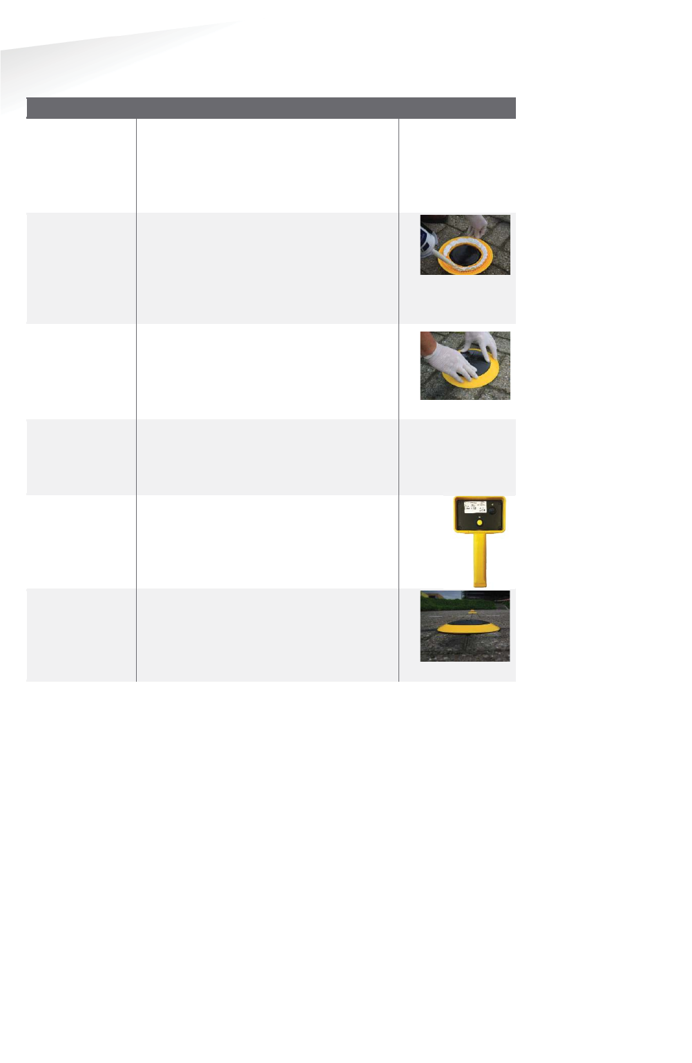
SENSIT SYSTEM | MANUAL
Mounting The SENSIT Surface Mount
57/
111
M
ountin
g
The SENSIT Sur
f
ace Moun
t
13.5.2 WITH THE CONFIGURATION TOOL
SSENSIT Surface Mount mounting procedure
Step 1:
Preparation
Indicate on the closed parking lot where
the SENSIT sensor should be mounted.
Clean the location where the sensor
should be mounted.
Distribute the SENSIT
sensors according your installation plan.
Step 2:
Gluing
Pour the filler into the mounting ring of
the SENSIT Surface Mount. A pneumatic
kit dispenser makes it easy to apply the
glue into the mounting ring. For good
fixture with the surface please fill the
entire mounting ring.
Step 3:
Mounting
Press firmly.
Step 4:
Cleaning-up
After mounting the SENSIT sensors in all
parking bays or a selection of parking
bays. Clean up the parking bays and
remove all (metal) tools and objects.
Step 5:
Activating
Segmentation
Calibrating
Use the Configuration Tool: Activate,
perform the segmentation according the
installation plan and calibrate the SENSIT
sensor.
SStep 7:
Glue curing
Leave the glue dry for at least 4 hours
before vehicles are allowed in the parking
space again.
Note
Ensure excessive glue is
removed from the bottom
black core part of the unit,
as this will make it very
difficult to replace the core
part.
For non
-permanent
mounting only glue the ring
with a few dots of glue.
Note
Once out of the
transport/stock mode the
battery lifetime starts to
count
.
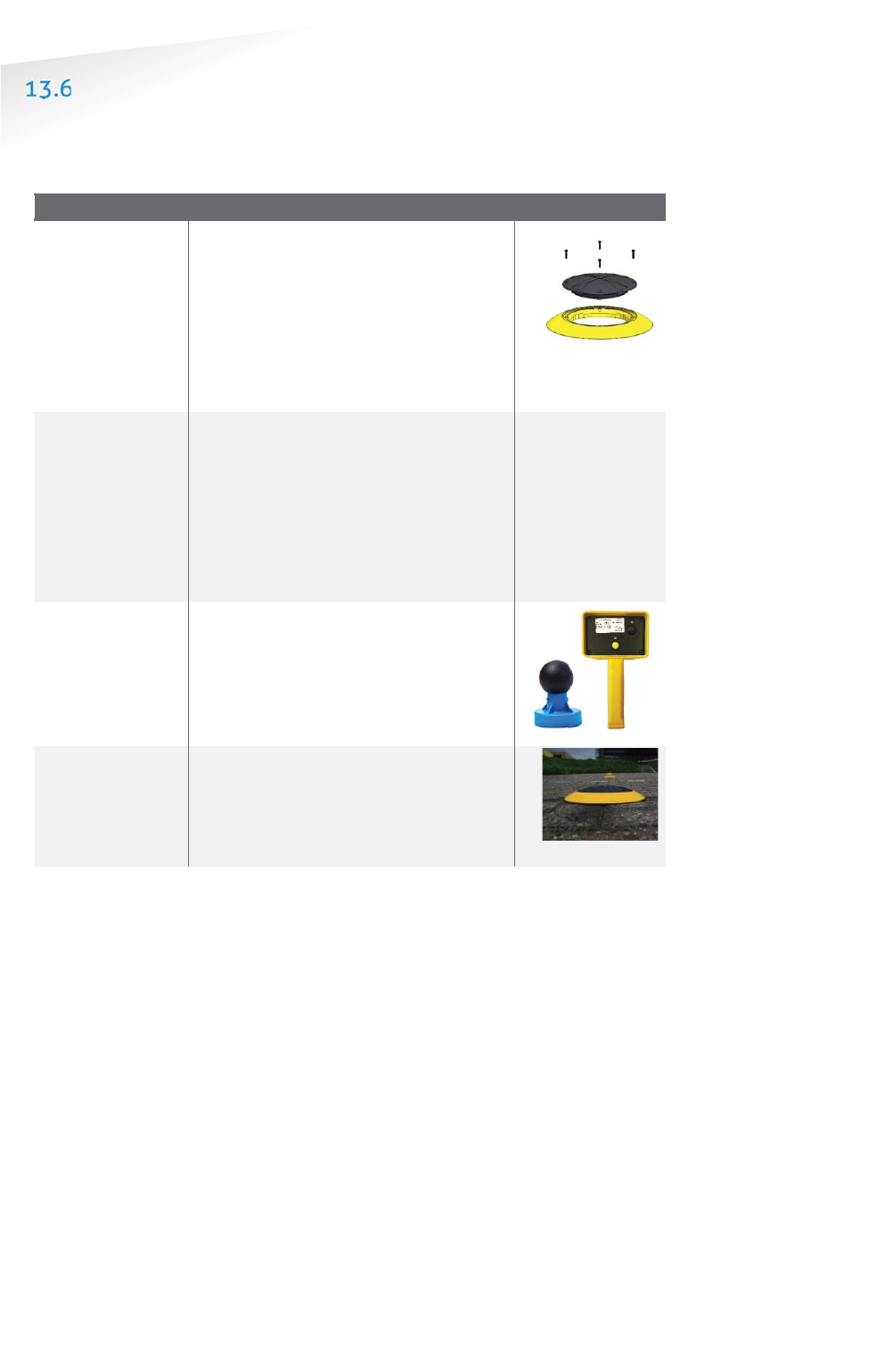
SENSIT SYSTEM | MANUAL
Mounting The SENSIT Surface Mount
58/
111
M
ountin
g
The SENSIT Sur
f
ace Moun
t
REPLACEMENT
When the battery life of the SENSIT Surface Mount fails after specified lifetime, we
advise to replace the core. The core part of the SENSIT Surface Mount is fully sealed
and for outdoor use, therefore batteries cannot be replaced.
SSENSIT Surface Mount rreplacement procedure
Step 1:
Remove core
The mounting ring can remain
positioned in the parking space. The
core can be unscrewed using a TORX
screwdriver. Unscrew the core by
opening the 4 screws in the core part of
the SENSIT Surface Mount using a T20
size bit screwdriver. Twist the core to lift
up.
Step 2:
Replace core
Place a new core into the mounting ring
by aligning the marks on the core part
with the marks on mounting ring as
indicated in figure 9. Strongly push
down the core and secure with
4 screws.
Write down the correct ID numbers of
the replaced core on your installation
plan.
Step 3:
Activating
(Segmentation)
Calibration
Activate the sensor, perform
segmentation when needed and
calibrate. Do this according the
procedures for with or without the
Configuration Tool as described in the
previous chapter.
SStep 44::
Update SIS
Ensure to note the node ID number of
the SENSIT Surface Mount to the parking
bay and update the parking bay
configuration list in the
SENSIT Interface
Software (SIS), see chapter 17.8.2
Note
Once out of
the
transport/stock mode the
b
attery lifetime starts to
count
.
Note
Also ensure not metal parts
(such as tools) aren’t
positioned in the
surrounding of the sensors
as this might affect
calibration.
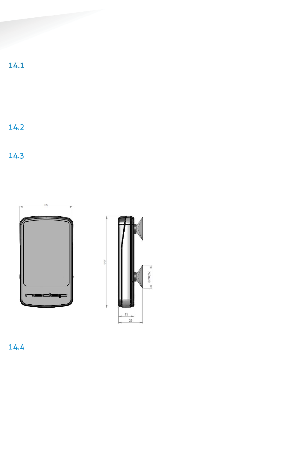
SENSIT SYSTEM | MANUAL
Mounting The SENSIT EPL
59/
111
M
ountin
g
The SENSIT EP
L
14 MOUNTING THE SENSIT EPL
The SENSIT EPL is designed for installations at the windscreen of a vehicle.
SAFETY PRECAUTIONS
The following safety precautions should be observed during normal use, service and
repair.
x The SENSIT EPL may only be installed and serviced by qualified service
personnel.
x To be sure of safety, do not modify or add anything to the SENSIT EPL other
than mentioned in this manual or indicated by NEDAP N.V.
IC AND FCC ID
FCC ID: CGDSENSITEPL and IC: 1444A-SENSITEPL
DIMENSIONS
The SENSIT EPL can easily be mounted on the inside of a vehicle. Clean the inside
surface of the windshield and make sure it free of grease and dirt. Than attaches, the
SENSIT EPL with the suction cups to the windscreen. See Figure 38 for the
dimensions of the unit, dimensions in mm. The bottom of the SENSIT EPL is laser
engraved with the node ID number.
Figure 38: Dimensions SENSIT EPL (mm).
REQUIRED INSTALLATION MATERIALS
The following would be required for mounting of the SENSIT EPL.
x Equipment: Soft lint free cloth
x Cleaner material: Isopropyl alcohol
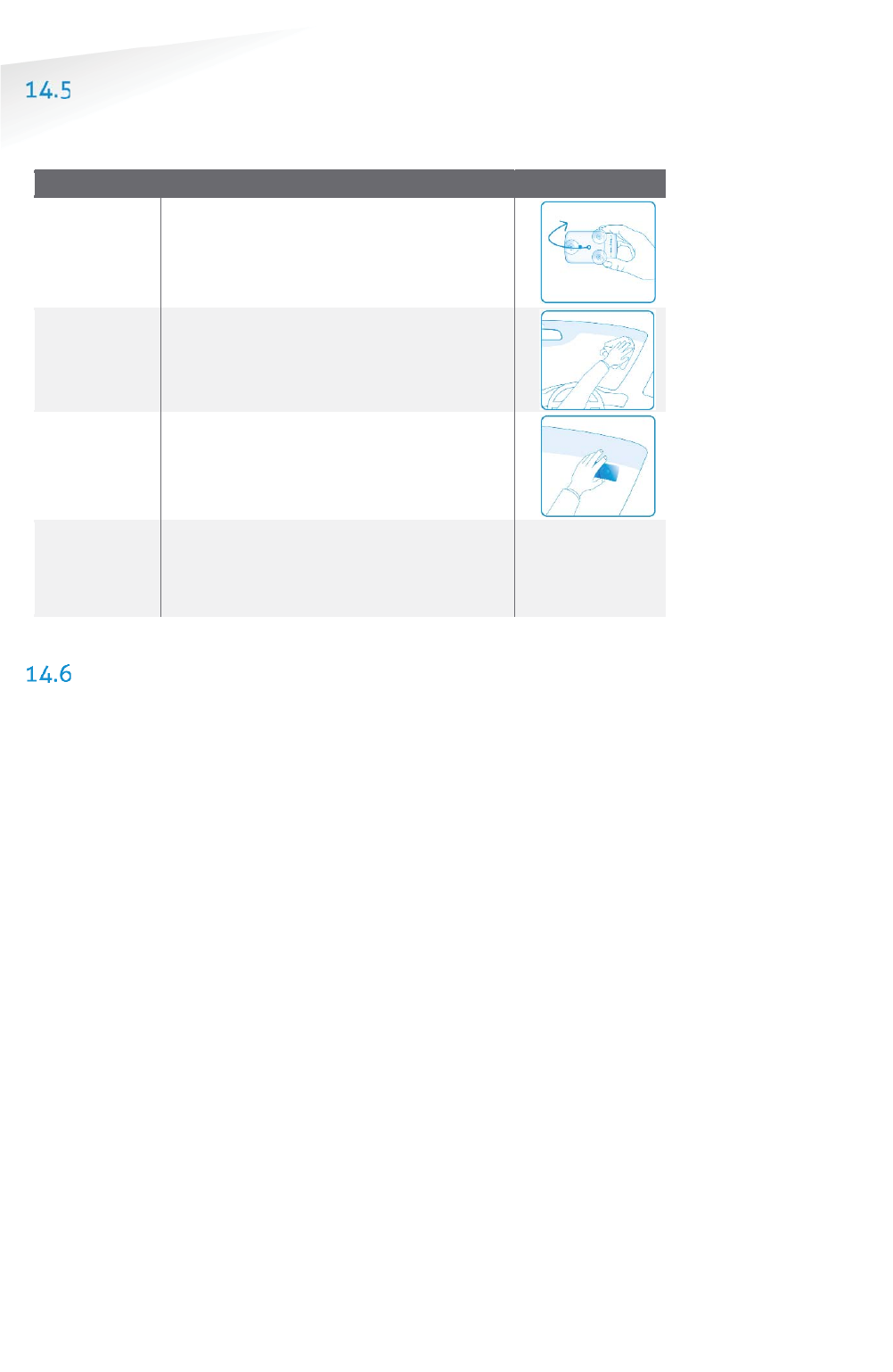
SENSIT SYSTEM | MANUAL
Mounting The SENSIT EPL
60/
111
M
ountin
g
The SENSIT EP
L
INSTALLATION PROCESS
Follow the recommended installation procedure for the SENSIT EPL as described
below.
SSENSIT Surface Mount mounting procedure
Step 1:
Preparation
Write down the unique ID-number of the
SENSIT EPL and insert the AAA alkaline
batteries.
Step 2:
Cleaning
Clean the windscreen at the location you
like to install the SENSIT EPL.
Step 3:
Mounting
A
ttach the SENSIT EPL with the suction cups
to the windscreen.
Step4:
Registration
Register the SENSIT EPL in the SIS by filling
in the permit details and the by Step1
written unique ID-
number, this explained in
more details in chapter 17.6.1.
SYSTEM SETUP FOR EPL
To get the best performance of detecting EPL’s in a SENSIT installation with different
segments the next steps have to be performed and checked.
1. The SIS needs accurate GPS coordinates of all system components; DC, RN
and SENSIT Sensors. The GPS coordinates can be uploaded into the SIS via
the Parking bay configuration menu see chapter 17.8.2.
2. All active system components (DC and RN) needs at least firmware version
2D.
3. The EPL needs at least firmware version 2D.
4. Segmentation announcement has to be enabled for all active system
components (DC and RN). Segmentation announcement can be enabled via
REST.
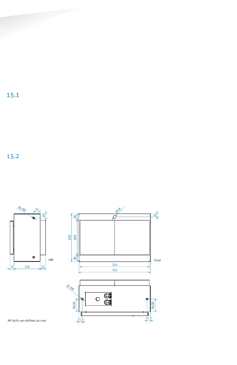
SENSIT SYSTEM | MANUAL
MOUNTING THE SENSIT DISPLAY
61/
111
MO
UN
TI
NG
THE
S
EN
SI
T
DI
SP
LA
Y
15 MOUNTING THE SENSIT DISPLAY
The SENSIT Display enables signage of available parking spaces for stand-alone
parking guidance installations. The display is designed for outdoor use, indicating
the number of available parking spaces per parking lot thus guiding motorists to the
closest parking space.
The display has adequate mechanical protection to withstand demanding
environmental conditions and automatic regulation of LED luminance to optimally
adept to surrounding conditions.
SAFETY PRECAUTIONS
The following safety precautions should be observed during normal use, service and
repair:
x The SENSIT Display may only be installed and serviced by qualified service
personnel.
x Disconnect the power supply before removing or installing any parts.
x To be sure of safety, do not modify or add anything to the SENSIT Display
other than mentioned in this manual or indicated by NEDAP N.V.
DIMENSIONS
In general the SENSIT Display is mounted inside a sign to be part of a (small)
dynamic guidance system. The only requirements are an AC mains power supply and
an Ethernet connection it is also possible to power the display over a PoE+
connection. The ambient light sensor for the automatic regulation of the LED
luminance is located just above the LED’s in the center of the sign. The mounting
dimension can be found below.
Figure 39: Dimensions SENSIT DISPLAY (mm).
Note
Make sure the ambient light
sensor isn’t covered.
Note
6x M5x15mm stainless
steel bolts are included

SENSIT SYSTEM | MANUAL
Project Support
62/
111
P
roject
S
u
pp
or
t
16 PROJECT SUPPORT
Based on our thorough project analysis including configuration and installation
advice we can offer the customer the best AVI solution.
SITE SURVEY & INSTALLATION ADVICE
This will consist of an engineer visiting the site to visually inspect and analyze the
location. We will then carry out calculations and provide you with detailed
configuration and installation advice for the equipment for a specific project.
ON-SITE CERTIFICATION
An engineer will visit the site to inspect the installation of the equipment on reliable
and accurate detection. Nedap engineers are not involved in installation (wiring) of
any equipment. The installation must be completed before the engineer arrives on-
site. We will ensure that the operation confirms our commissioning requirements,
only on condition of prior given installation advice.

SENSIT SYSTEM | MANUAL
SENSIT Interface Software
63/
111
SE
NS
IT I
nt
er
fa
ce
S
of
tw
ar
e
17 SENSIT INTERFACE SOFTWARE
INTRODUCTION
The SENSIT Interface Software (SIS) enables easy system integration into an
enforcement, traffic guidance or parking guidance management application.
The SENSIT Interface Software enables easy installation of the wireless sensor
network. Once the network and sensors are installed and calibrated, the sensors will
automatically appear in the software. Configuration of sensors to specific parking
bays, parking zones and parking lot can easily be realized.
Additionally the software configures and monitors communication of the SENSIT
node network. It monitors the data transfer between the sensors and the SENSIT
Gateways. Moreover it also analyzes communication reliability of the sensor network
in a graphical map, automatically alerting areas for maintenance.
The SENSIT Interface Software is installed on a hosted server, so no IT infrastructure
is required at the client. The software application can be approached with any
modern web browser that supports Java can connect to the software application.
Each sensor site has a site specific URL indicated in the following way;
https://sitename.nedapparking.com
USERS
Start the web browser and enter the SENSIT Server hostname. A login screen will
appear.
Please view the document outlining the SENSIT Gateway configuration settings for
the details on the URL, login and password for your site. This information is required
to obtain access.
17.2.1 LOGIN
The login screen provides access to the software. Enter username and password.
Figure 40: Login screen

SENSIT SYSTEM | MANUAL
SENSIT Interface Software
64/
111
SE
NS
IT I
nt
er
fa
ce
S
of
tw
ar
e
17.2.2 DEFAULT LOGINS
User: sensit
The SENSIT user has reduced functionality in the software. Only a subset of these
options is available via the user login. Basically this login is available to check the
status of the system. It does not allow changing the configuration or any other
settings.
User: parkingapp
This login has reduced functionality in the software and is used for the Nedap
parking app.
User: integrator
This user has reduced functionality in the software, used for third party integration
via REST or SOAP.
User: sensitadv
This user has advanced functions and configuration possibilities.
The initial username and password are provided to you by Nedap.
17.2.3 LOGOUT
Click 'Logout' when you want to close the application.
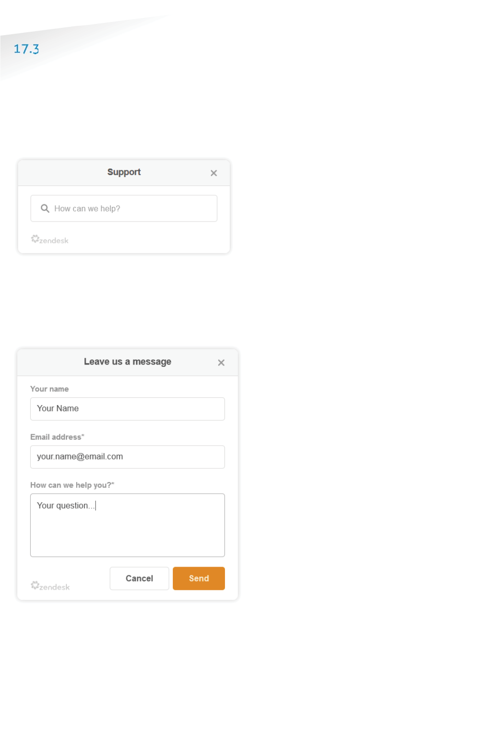
SENSIT SYSTEM | MANUAL
SENSIT Interface Software
65/
111
SE
NS
IT I
nt
er
fa
ce
S
of
tw
ar
e
SUPPORT WIDGET
The Web Widget enables you to answer your questions without leaving the SIS
webpage. You can get quick access to and search for knowledge base articles or
send a question to our support. .
The support button appears in the top corner of every SIS page, just beside the
logout button. When you click the Support button a search window appears in the
bottom right corner, here you can type your search phrase, see figure below.
Figure 41: Support knowledge base search
When this knowledge base doesn’t answer your question you can easily contact the
helpdesk by filling in a contact form to submit a ticket, see figure below. After
sending the question you will receive a confirmation by email with a new ticket
number.
Figure 42: Contact form
Note
The Support Widget is only
available at Nedap hosted
SIS installation.
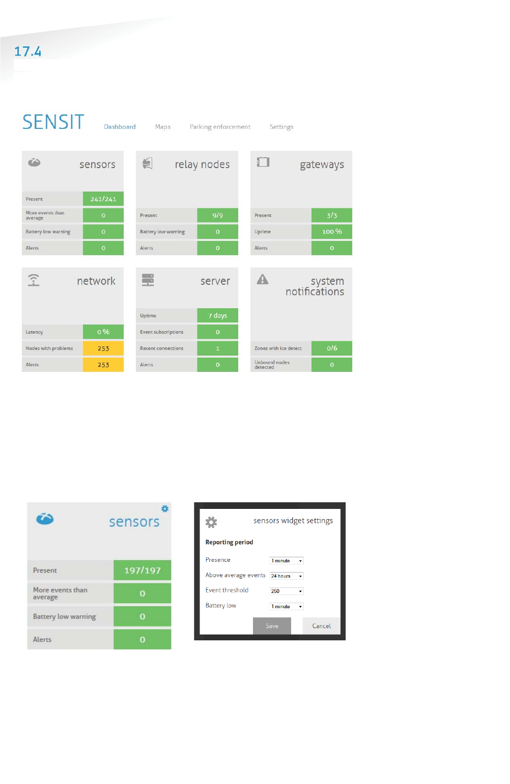
SENSIT SYSTEM | MANUAL
SENSIT Interface Software
66/
111
SE
NS
IT I
nt
er
fa
ce
S
of
tw
ar
e
DASHBOARD
The Dashboard is designed to give the user an overview on how the SENSIT system
is performing. The Dashboard page contains several Widgets. A Widget summarizes
and displays the actual state of SENSIT system.
Figure 43: Dashboard screen
The Dashboard contains six main Widget categories: SENSIT sensor, Relay Nodes,
Gateways, The wireless Network, the Server and system notifications.
The functions of the Dashboard are self-explaining by hover over pop-ups and help
balloons when needed. Every widget can be configured via the configuration symbol
at the right corner of every widget, see figure below. The configuration symbol will
automatically show if you move your mouse to the specific widget. In this screen
you can change the different widget settings.
Figure 44: Configuration symbol and widget settings screen
Note
Configuration is only
available under sensitadv
login.
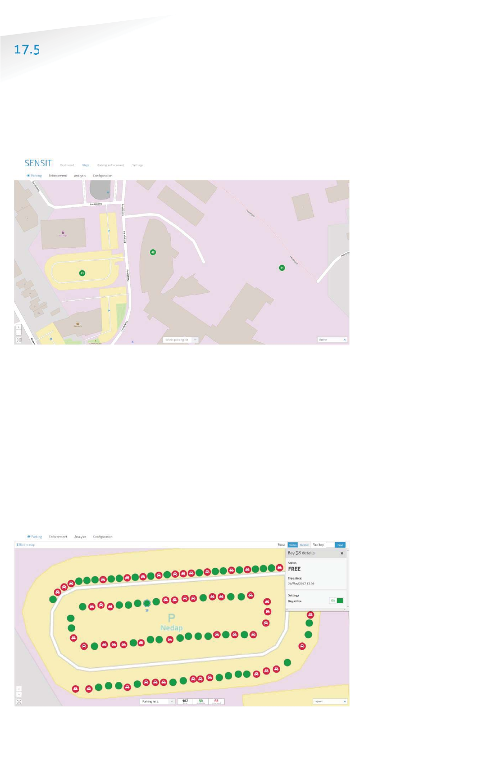
SENSIT SYSTEM | MANUAL
SENSIT Interface Software
67/
111
SE
NS
IT I
nt
er
fa
ce
S
of
tw
ar
e
MAPS
The SIS is more map orientated. The Maps will show the actual parking lot status on
an overview map and in more details. The SENSIT are placed on the map and their
colors indicate the actual status. The SENSIT and other nodes can be placed on the
open street map automatically when the GPS coordinates of all nodes are provided.
It is also possible to configure your own map (SVG-file). See chapter 17.8.4 how to
configure the overview map.
Figure 45: Overview map
The Maps has four main function:
1. Parking, showing the occupancy of the parking lots.
2. Enforcement, showing violations and overstays at the parking lots
3. Analysis, showing the Wireless SENSIT Network status, the segmentation
and the sensor details.
4. Configuration, makes it possible to move the system component into the
right location at the map.
17.5.1 PARKING
At the parking map you can find the number of occupied and available bays. This can
be showed for the whole system or per individual parking lot. At parking lot level the
user can select a bay to get some more details and to individually deactivate a bay.
Figure 46: Parking map, available and occupied bays. Bay 38 is selected
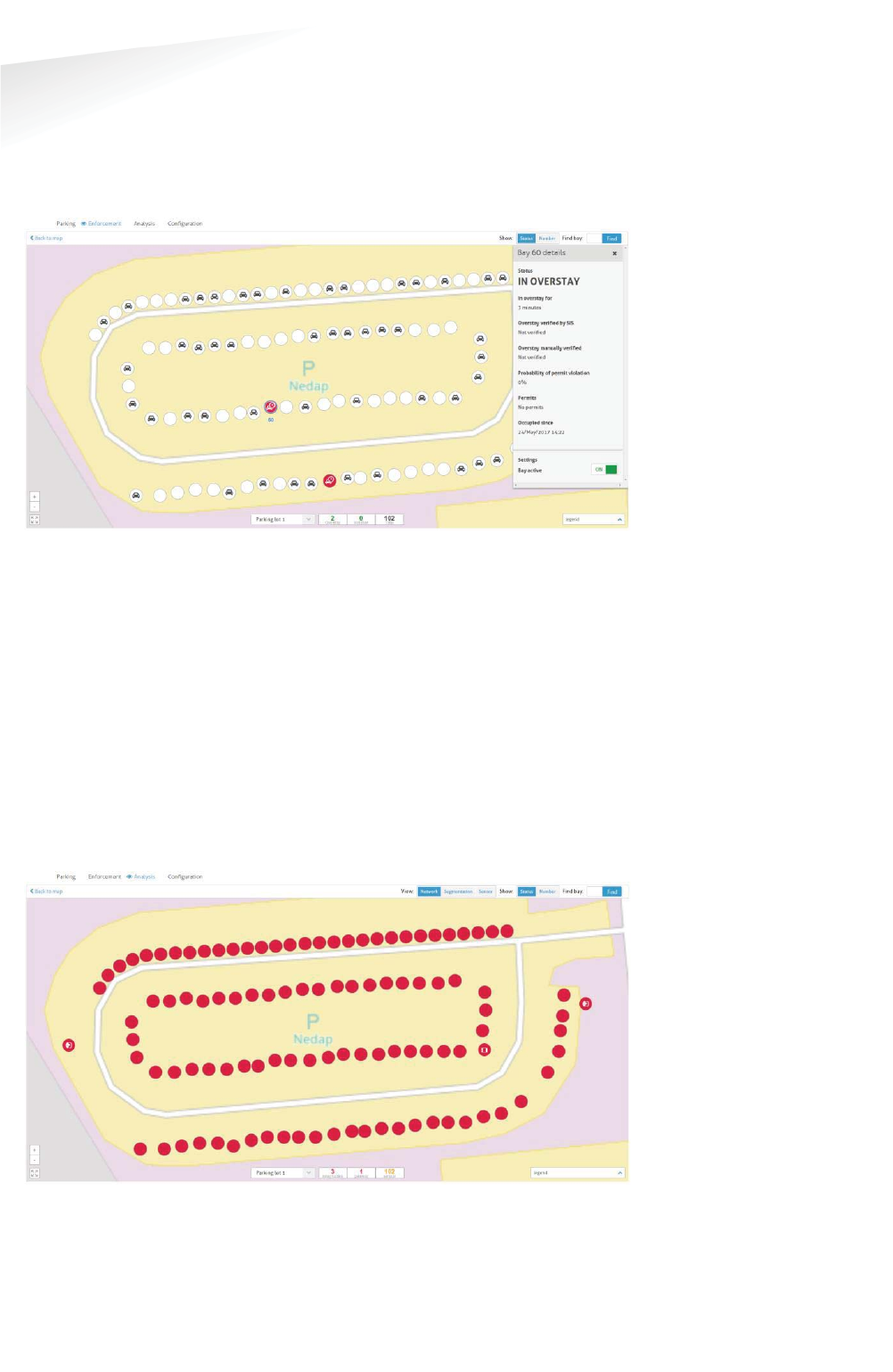
SENSIT SYSTEM | MANUAL
SENSIT Interface Software
68/
111
SE
NS
IT I
nt
er
fa
ce
S
of
tw
ar
e
17.5.2 ENFORCEMENT
The enforcement map shows all violation and overstays of the system. This can be
showed for the whole system or per individual parking lot. At parking lot level the
user can select a bay to get some more details and also to individually deactivate a
bay.
Figure 47: Parking map, violations and overstays.
17.5.3 ANALYSIS
The analysis map shows three different views; Network-, segmentation- and sensor
view. The analysis map can be used to identify in more details possible issues with
the system or a specific sensor.
The network view indicates the uptime of every individual SENSIT component. Also
at the overview map the number of SENSIT components with uptime issue are
shown.
Also at parking lot level the individual SENSIT components are marked red when the
uptime is too low. Below an example of a just installed parking lot were all bays,
Relay Node and Gateway indicate a poor uptime.
Figure 48: Network view.
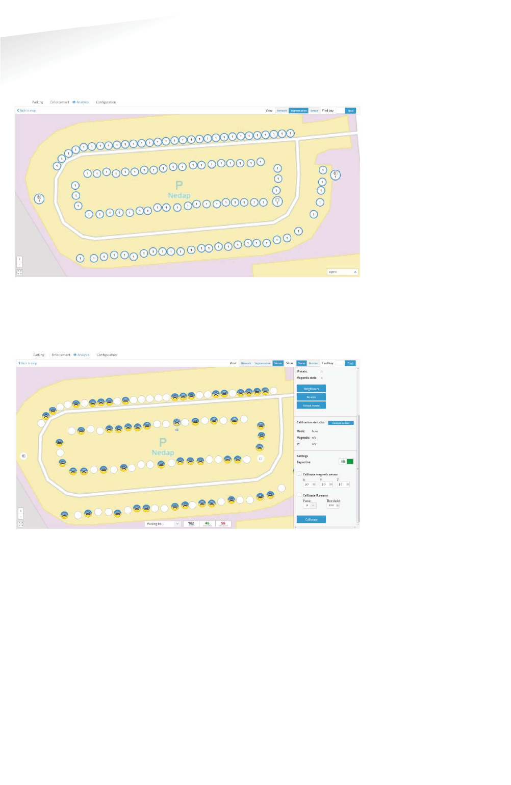
SENSIT SYSTEM | MANUAL
SENSIT Interface Software
69/
111
SE
NS
IT I
nt
er
fa
ce
S
of
tw
ar
e
Segmentation of larger parking lot is often needed to get a better performance and
lower latency. In the segmentation view a single SENSIT component can be selected
whereupon al corresponding nodes with the same segment number will light up
blue.
Figure 49: Segmentation view.
At the sensor view every individual bay can be monitor about its sensor states (IR
and magnetic) also the sensor can be calibrated. Both the IR sensor as the magnetic
sensor can be calibrated independantly.
Figure 50: Sensor view.
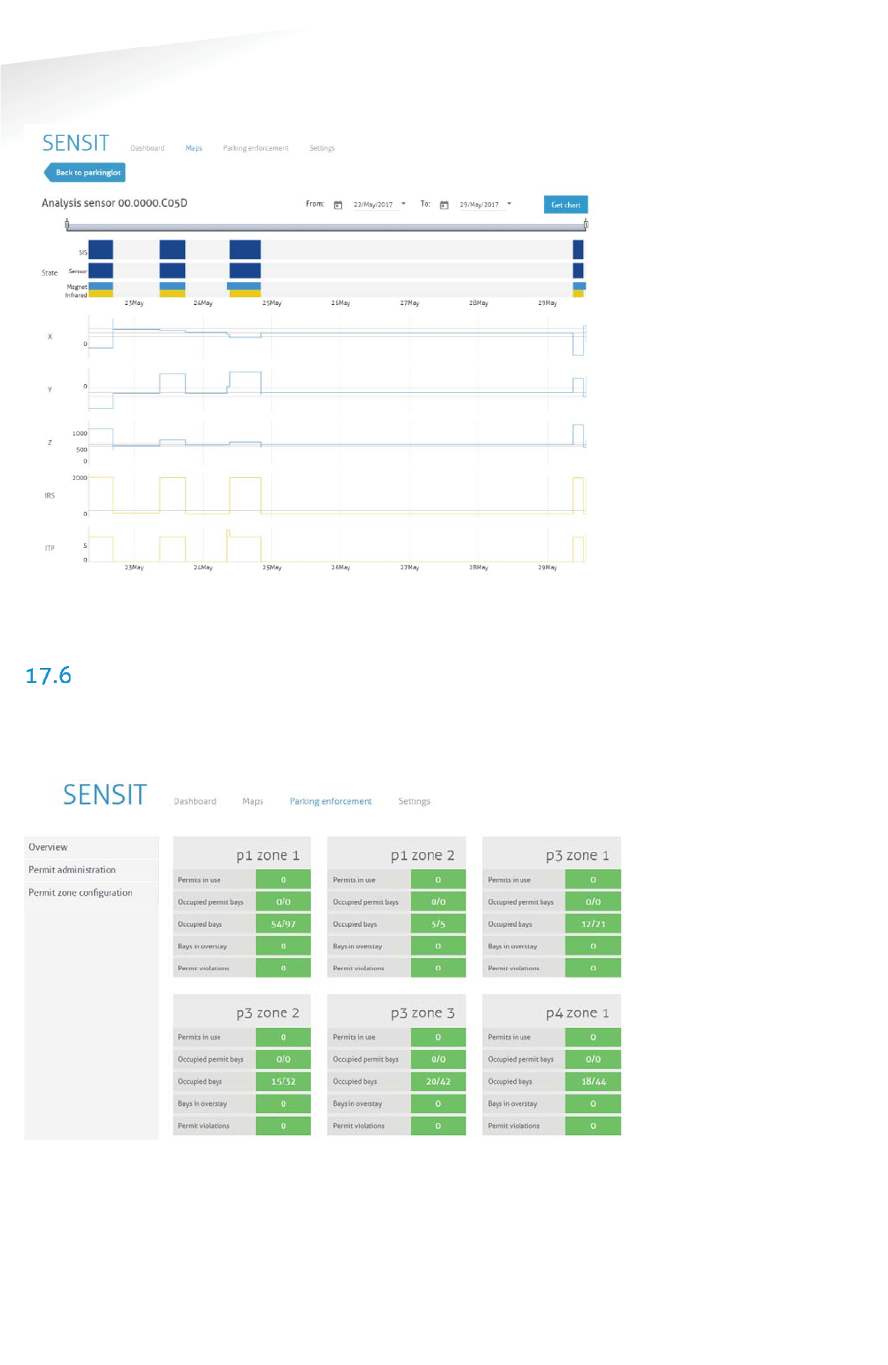
SENSIT SYSTEM | MANUAL
SENSIT Interface Software
70/
111
SE
NS
IT I
nt
er
fa
ce
S
of
tw
ar
e
In this sensor view the IR and magnetic sensor can be analyzed as well as the SENSIT
sensor and SIS conclusions by selecting the bay and click the Analyze sensor button.
Figure 51: Analysis sensor view.
PARKING ENFORCEMENT
The Parking enforcement is a secondary dashboard, designed to give the user an
overview on all parking enforcement related information. This parking enforcement
dashboard summarizes and displays the actual status of a specific parking zone.
Figure 52: Parking enforcement dashboard screen
Different enforcement information of all parking zones are displayed: Permits in use,
Occupied permit bays, Occupied bays, Bays in overstay and the Permit violations.
The Electronic Parking License (EPL) is a hardware device that is physically placed
inside a vehicle or it is an App that is running on a smartphone. Whenever the
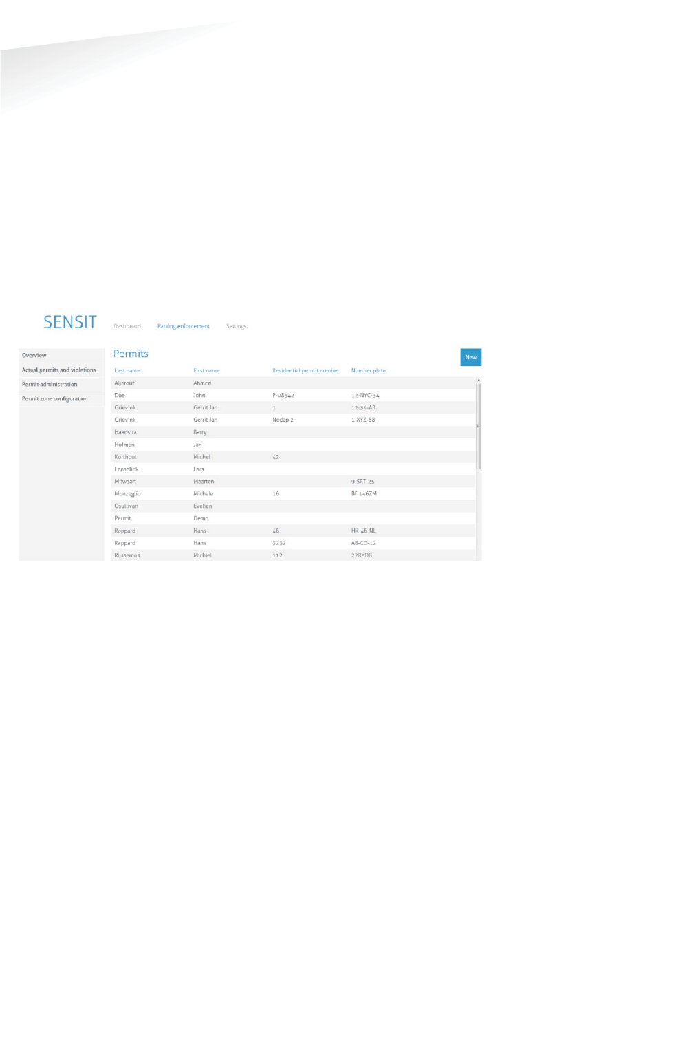
SENSIT SYSTEM | MANUAL
SENSIT Interface Software
71/
111
SE
NS
IT I
nt
e
r
f
ac
e
So
ft
wa
re
vehicle with EPL hardware stops moving for a specific period of time, the EPL
considers the vehicle to be parked. In that case, the EPL hardware will search for a
SENSIT wireless network. If a network is detected, the EPL will make itself known to
the network. As a result the unique EPL identifier is registered within the SENSIT
Server system. The user of the EPL App is doing the same, it activates the parking
action with it smartphone.
When a parking bay that requires a license, becomes occupied, the SENSIT system is
notified. The system will calculate the odds of the parking bay being occupied by an
unauthorized vehicle.
17.6.1 PERMIT ADMINISTRATION
In these screens all permit administration is performed. A permit is issued to a
person and it can be a hardware EPL or an EPL App installed on a smart phone.
Figure 53: Permit administration screen
New permits can be added and existing permits can be edited or removed. A
Residential permit number can be enter, name, license plate number and the EPL
node ID in case of a issued hardware EPL. The permit can be disable and an
expiration date can be used, an empty expiration date means valid forever. Than one
or multiple parking zones can be selected where the permit is valid. Zone creation is
explained in the next paragraph.
Note
An EPL is only valid for a
selected (blue highlighted)
Permit zone.
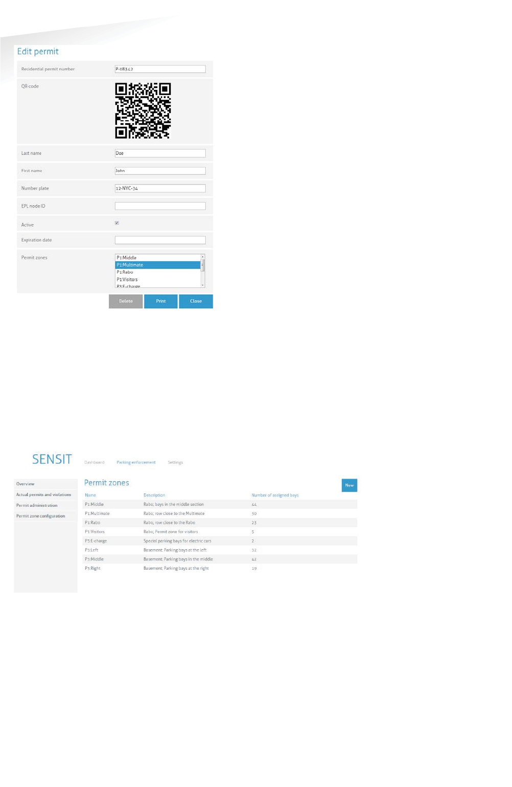
SENSIT SYSTEM | MANUAL
SENSIT Interface Software
72/
111
SE
NS
IT I
nt
er
fa
ce
S
of
tw
ar
e
Figure 54: Edit permit screen
After creating a new permit, by filling in all needed details, a QR-code is
automatically generated. The EPL App needs this QR-code. The QR-code contains the
URL of the SIS where the permit is created and a unique identifier.
17.6.2 PERMIT ZONE CONFIGURATION
In these screens all permit zone configuration is performed. A permit zone is a
selection of one or multiple parking bays. A list of all available, already entered,
zones are displayed in the screen below.
Figure 55: Permit zone configuration screen
New permit zones can be added and existing permits zones can be edited or
removed. A permit zone name and description can be entered and the bays can be
assigned in the selection screen.
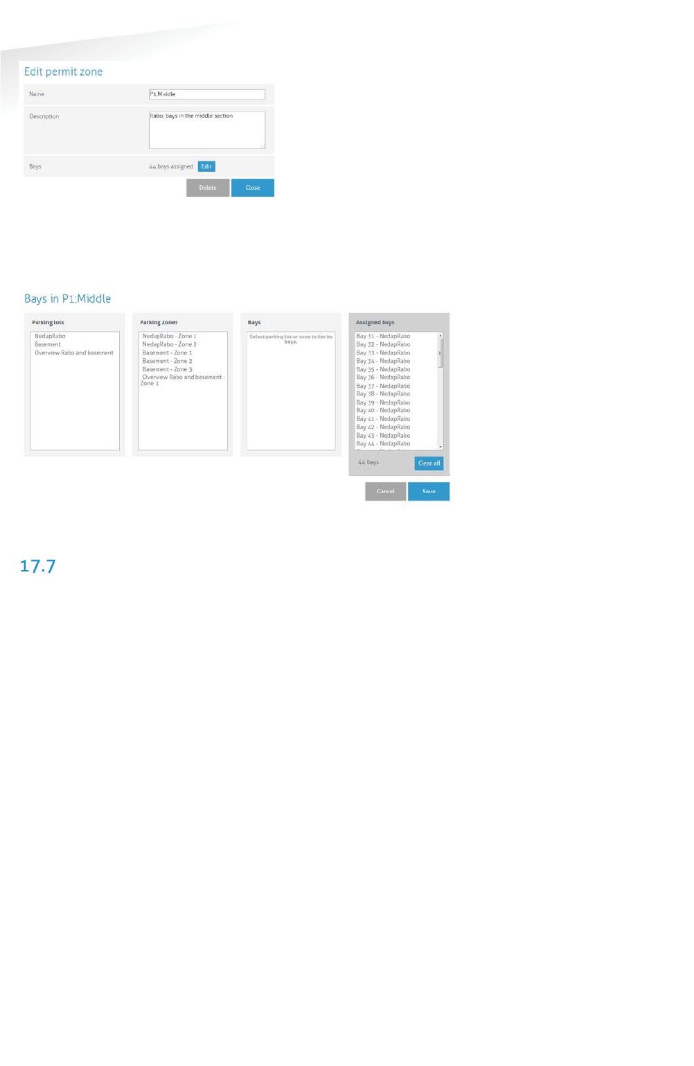
SENSIT SYSTEM | MANUAL
SENSIT Interface Software
73/
111
SE
NS
IT I
nt
er
fa
ce
S
of
tw
ar
e
Figure 56: Add/Edit a permit zone screen
A permit zone can be a parking lot(s), a parking zone(s), one or a selection of bays.
This can easily be selected in the screen below.
Figure 57: Permit zone bays assignment screen
DETECTION
17.7.1 GATEWAY
In the SENSIT Gateway menu you can configure communication gateway settings
between the SENSIT Gateways and the SENSIT Server. Furthermore the screen
provides an overview of the current SENSIT Gateway settings. The list of SENSIT
Gateways is automatically updated.
Gateway server setting
Select 'enabled' to enable the connection from SENSIT Gateway to the server. Enter
the TCP port (or default SSL port), to accept connections from the SENSIT Gateway(s).
For a remote hosted SENSIT Server, the port number should not be changed.
Because the port numbers are assigned by the Nedap system administrator.
SENSIT Gateway connection settings
In this menu you can set 'Host name' and communication 'Port' for the SENSIT
Gateway. The SENSIT Gateway is displayed as a node, see below. The hostname of
the SENSIT Gateway can normally be found on the housing. The SENSIT Server will
try to establish a connection with the specified SENSIT Gateway. This does not work
on remote hosted SENSIT Servers. See gateway server settings above.
The screen provides an overview of the current SENSIT Gateway settings. When
entering new SENSIT Gateways, the table is automatically updated.
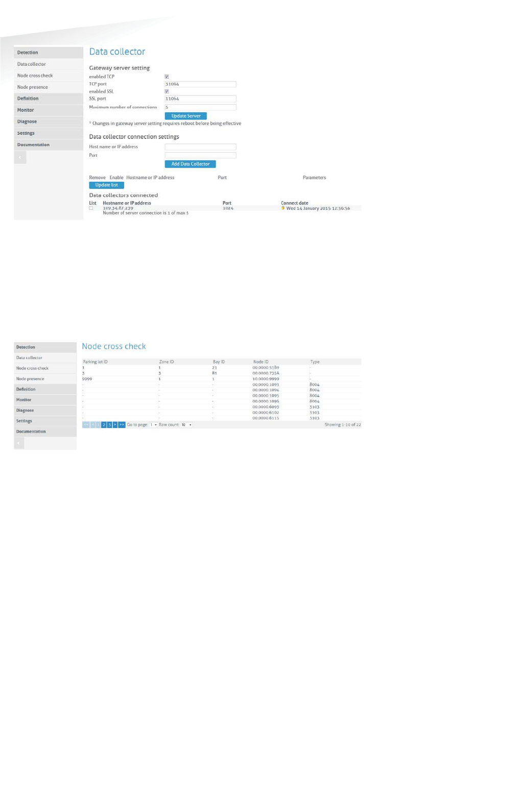
SENSIT SYSTEM | MANUAL
SENSIT Interface Software
74/
111
SE
NS
IT I
nt
er
fa
ce
S
of
tw
ar
e
Figure 58: SENSIT Gateway server settings
17.7.2 NODE CROSS CHECK
The menu option 'Node cross check' displays all nodes currently visible in the
system that are not allocated to a parking bay. These could be new or replaced
SENSITs, but also the Relay Nodes and SENSIT Gateways are shown here. Moreover
this screen also displays parking bays without a node (if this information is entered
via the parking bay configuration).
Figure 59: Node cross check
17.7.3 NODE PRESENCE
This screen will display information on the last received message from each node
present in the network. It will outline the Node ID, type number, version and the
timestamp of the last received message.
Node presence check (min)
If a node does not respond within a certain time period (default: 720 minutes) after
transmission of the last message, the SENSIT Server will check if the node is still
available. In this menu option you can select the time after receiving the last
message (in minutes) when to send the Node presence check.
Node presence check retry
The 'Node presence check retry' specifies the number of times (default: 4) the
SENSIT Server shall try to connect to the node.
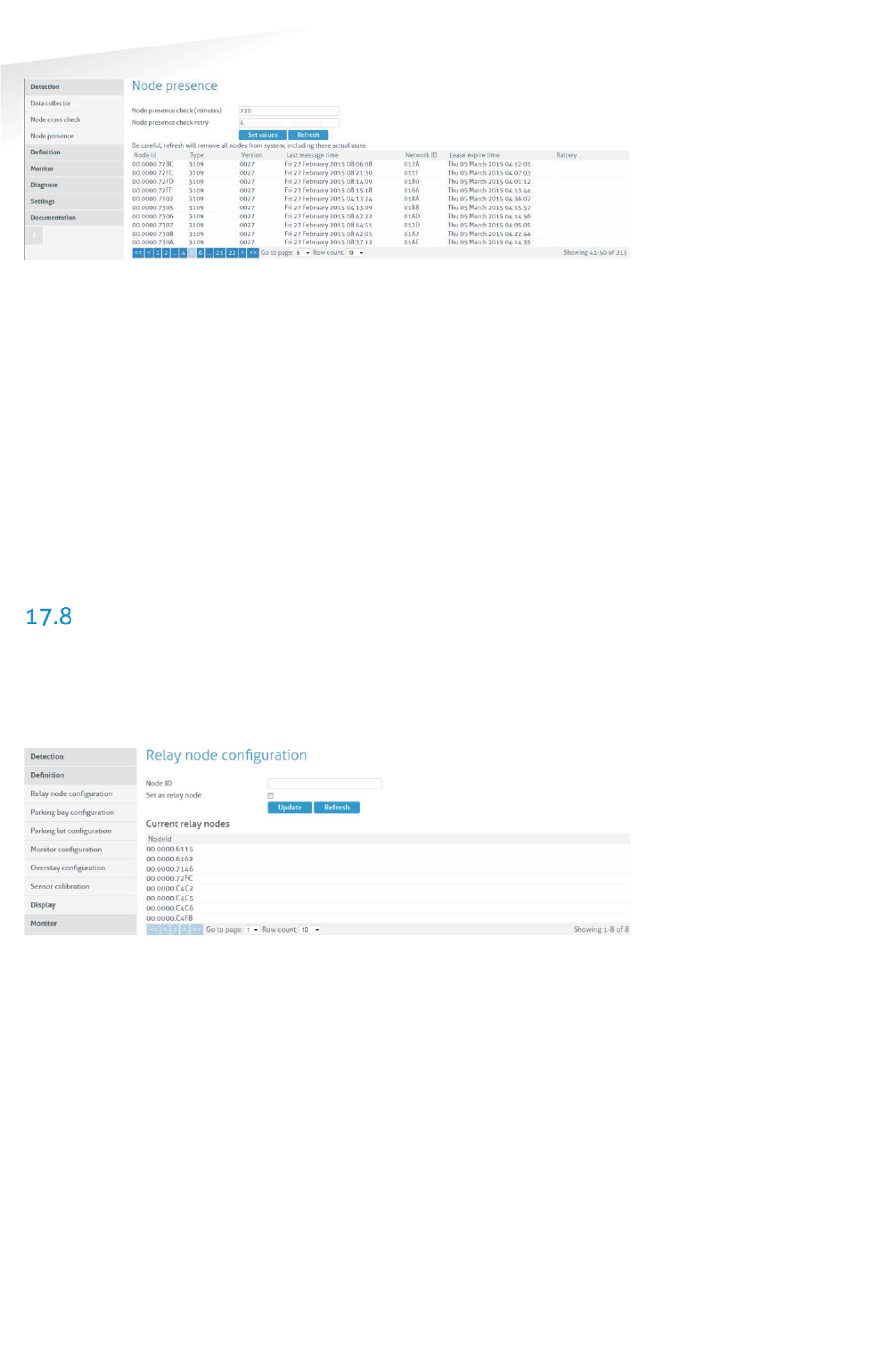
SENSIT SYSTEM | MANUAL
SENSIT Interface Software
75/
111
SE
NS
IT I
nt
er
fa
ce
S
of
tw
ar
e
Figure 60: Node presence
In the screenshot above several nodes are listed in the node cross check.
For example node id 00.0000.72BC is a SENSIT IR (type 3109). Every different type
of node has its own Type code, see below the general use types:
Type code
Node description
000c
0017
Data Collector
SENSIT Gateway
0018
Relay Node 2G
3003
Relay Node 1G
3109
SENSIT Flush Mount or SENSIT IR
310D
SENSIT Flush Mount or SENSIT IR
310E
Electronic Parking License (EPL)
8004
WSN Display
DEFINITION
17.8.1 RELAY NODE CONFIGURATION
You can click the Refresh button and verify if the Relay Node ID appears in the
Current Relay Nodes list.
Figure 61: Relay Node configuration screen
The Relay Node ID is laser engraved on the Relay Node. There is also a 125kHz
passive RFID label embedded into the Relay Node. This can be used for verification
of the Relay Node or to localize Relay Nodes that are already installed in the field.
17.8.2 PARKING BAY CONFIGURATION
In the menu 'Parking bay configuration' SENSITs are allocated by their Node ID to
individual parking bays.
The data is imported into the system via a csv-file (comma separated values). The
following information should be entered into the csv-file separated by a comma (' ,
'). Note that the combination of parking lot-id and bay-number must be unique.
Column 1 Parking lot ID (number indicating the parking lot).
Column 2 Zone ID (number indicating zone on the parking lot the bay is

SENSIT SYSTEM | MANUAL
SENSIT Interface Software
76/
111
SE
NS
IT I
nt
er
fa
ce
S
of
tw
ar
e
located in) Zone ID is also used to identify Relay Node (RN) or
Gateway/DataCollector (DC).
Column 3 Bay number (number indicating individual parking bay).
Bay number is also used to number a Relay Node or Data Collector
Column 4 Node ID. (SENSIT, Relay Node or Gateway/DataCollector)
Column 5 GPS, Latitude (optional, decimal degrees with min. 6 decimals).
Column 6 GPS, Longitude (optional, decimal degrees with min. 6 decimals).
Column 7 GPS, Altitude (optional, decimal degrees with min. 6 decimals).
Figure 62: Example parking bay configuration csv-file
Select the csv-file by clicking the 'Browse'-button, then click 'Import' to import the
selected file.
When the csv-file is imported, the screen will display the information. At each given
moment you can verify in this table the allocated SENSIT / Parking bay bindings.
Refer to the node cross check display to verify if all SENSIT are assigned to a parking
bay (see chapter 17.7.2). It is possible to incrementally expand the Parking bay
configuration list by importing only additional allocation information (Parking lot ID,
Zone ID, bay/place number and Node ID) via a new csv-file.
Figure 63: Parking bay configuration
Click the small green checkbox icon to (temporarily) inform the system that the
parking bay is unavailable. Click the small pencil at the end of a row, an Update
Node ID screen shows up, here you can change the Node ID number and the GPS
coordinates. This can be used to replace a SENSIT or to correct a mistake.
Note
Ensure that the filename
and file path do not include
any spaces.
Note
The order of parkinglotid in
the Monitor configuration
screen determines the
order of TABs in the Monitor
map screen.
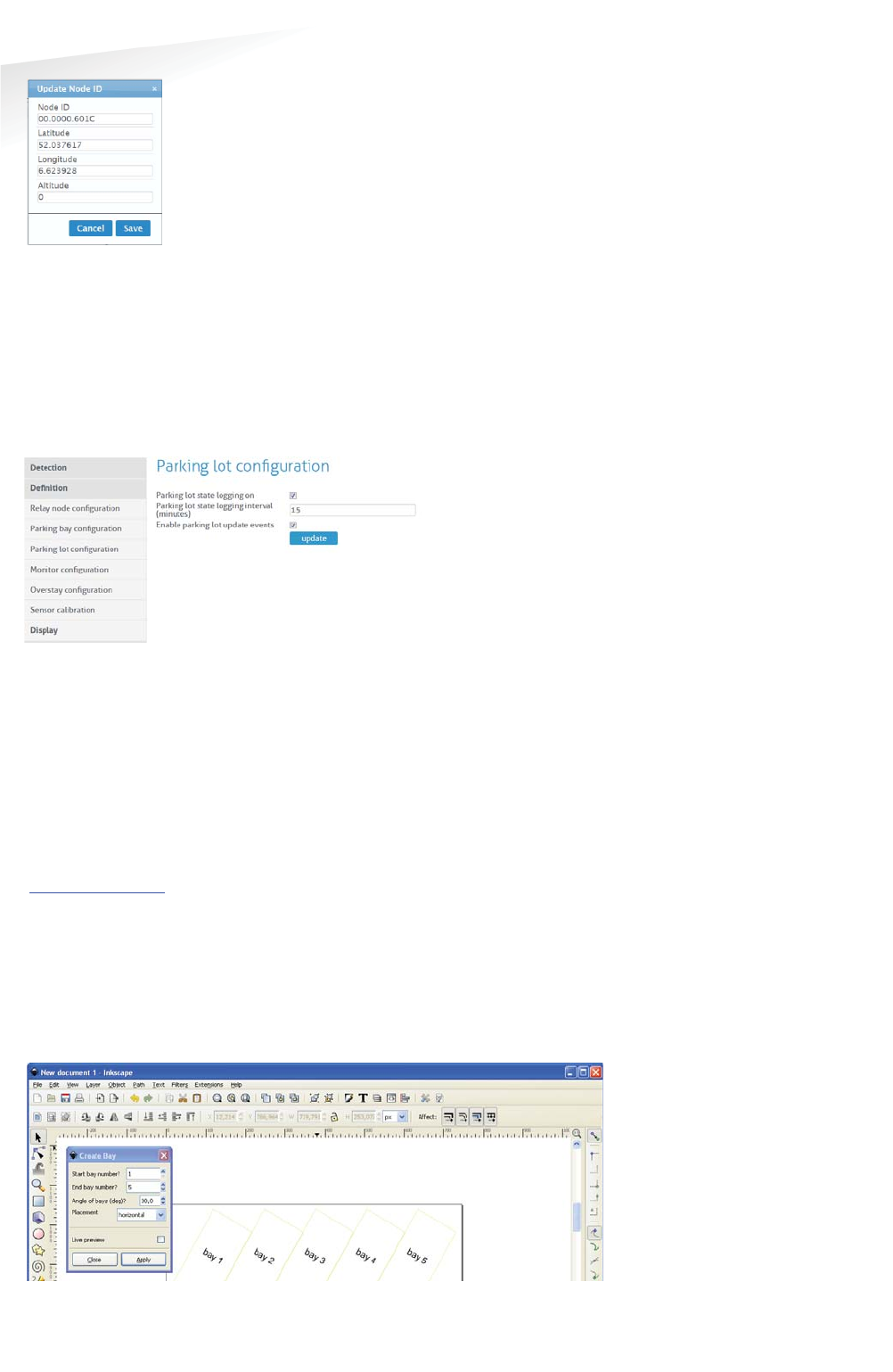
SENSIT SYSTEM | MANUAL
SENSIT Interface Software
77/
111
SE
NS
IT I
nt
er
fa
ce
S
of
tw
ar
e
Figure 64: Update Node ID
17.8.3 PARKING LOT CONFIGURATION
The parking state logging feature periodically saves occupancy status in the
database.
Enable the 'parking lot state logging on' checkbox to start logging occupancy status
of the parking lot in the database. The parking lot state logging interval setting
selects the logging period in minutes. By default this is set to 60 minutes.
Figure 65: Parking lot configuration
17.8.4 MONITOR CONFIGURATION
Site Name
Fill in here the site name.
Map List
Here you can load the parking lot graphic file (SVG-format) into the system and
assign it to a parking lot. The SVG-file can be created with Inkscape
(http://inkscape.org). Nedap has an extension available for Inkscape that should be
used to define where the parking bays are located on the map. See the advanced
section, chapter 18.1 for more explanation and the workflow about the Inkscape
program.
When the SVG-file is created, enter the ParkinglotID and the title. Then select the
svg-file by clicking the 'Browse'-button and click Upload' to upload the selected file
into the system.
Figure 66: Inkscape
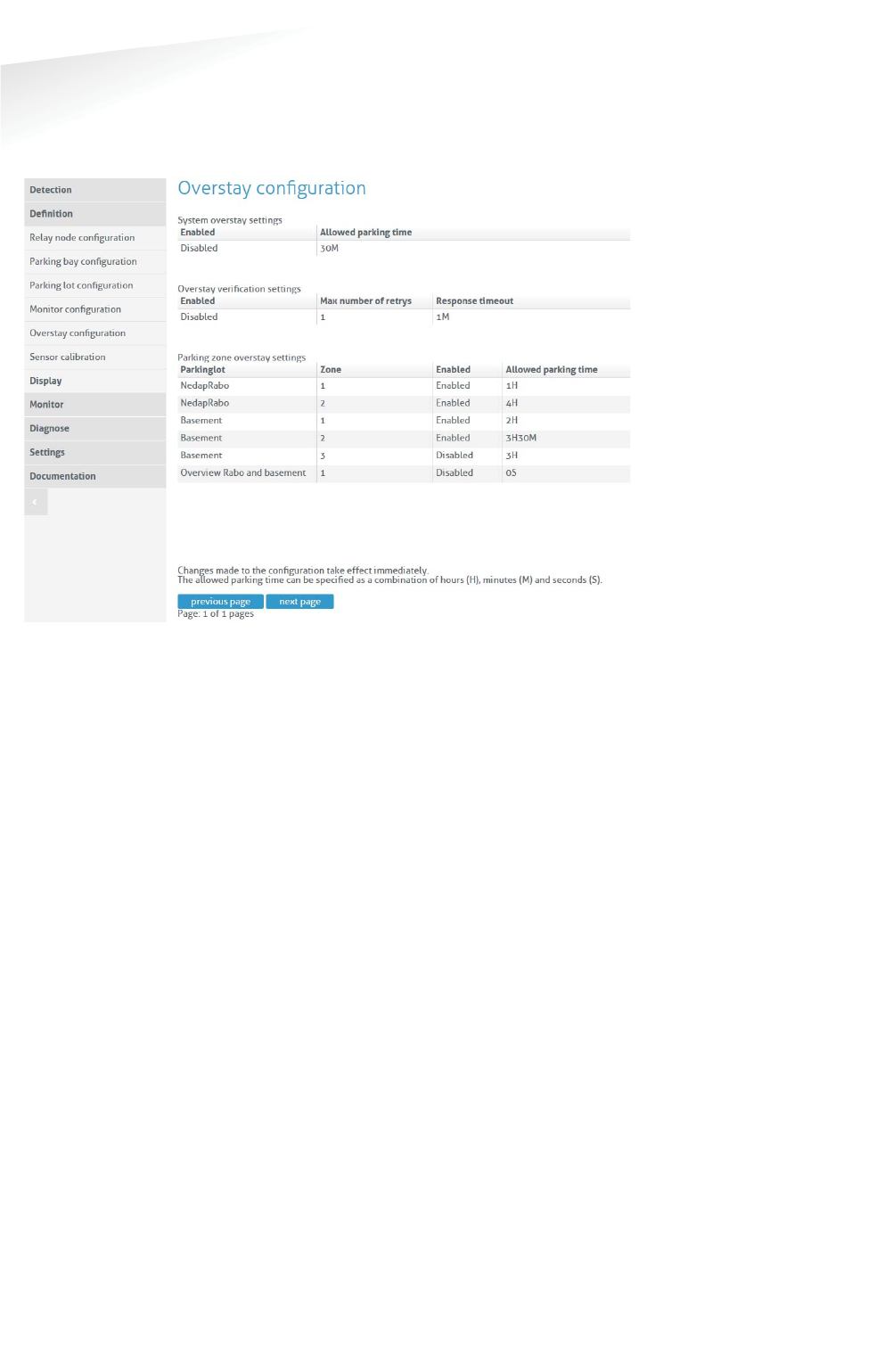
SENSIT SYSTEM | MANUAL
SENSIT Interface Software
78/
111
SE
NS
IT I
nt
er
fa
ce
S
of
tw
ar
e
17.8.5 OVERSTAY CONFIGURATION
The SENSIT Server can be used for overstay applications, specifically where there is
a need for a maximum time limit for free parking. The menu 'Overstay configuration'
allows you to set several overstay parameters.
Figure 67: Overstay configuration
System overstay settings
With this option the global overstay function can be enabled. The settable Allowed
parking time is the overstay time for all SENSIT sensors defined at the SENSIT
Interface Server. This setting determines how long a parking bay should be occupied
before an overstay situation occurs.
Overstay verification settings
When enabled, the SENSIT Interface Server will ask the SENSIT sensor if all state
events are received in case of an overstay. The last state event message is
transmitted again to the SENSIT Server to verify the overstay.
The Max number of retries (max value is 5) can be set. If an overstay verification fail
it retry to receive the last state event message. If the final overstay verify attempts
fail an unverified overstay event is generated.
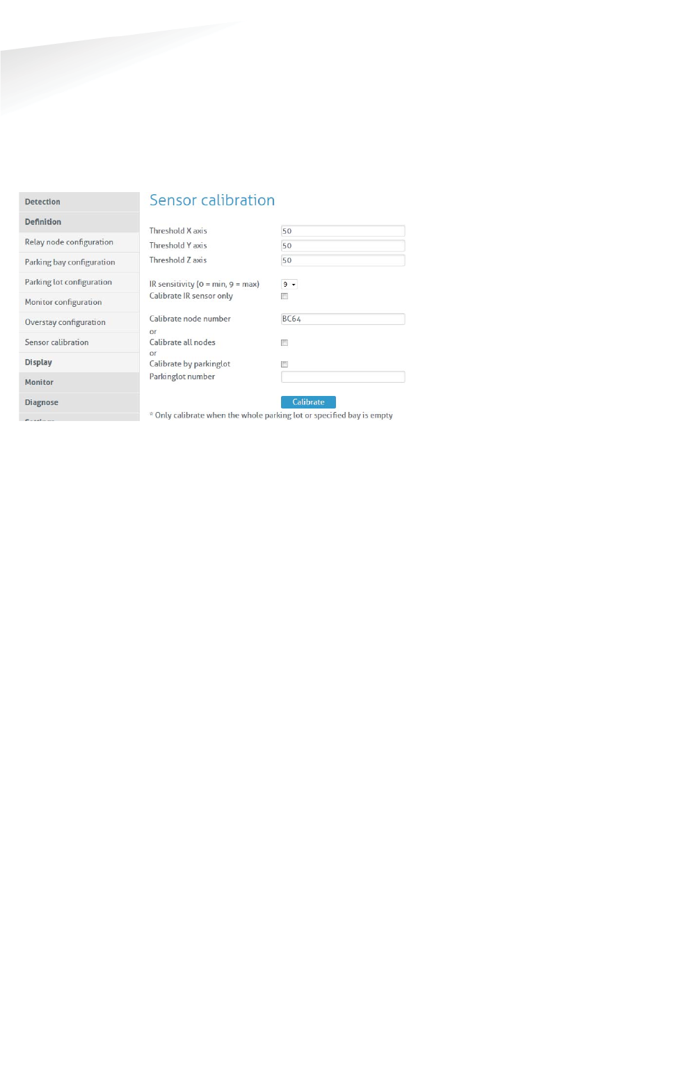
SENSIT SYSTEM | MANUAL
SENSIT Interface Software
79/
111
SE
NS
IT I
nt
er
fa
ce
S
of
tw
ar
e
17.8.6 SENSOR CALIBRATION
To ensure reliable operation of the system the SENSIT sensors should be calibrated
before commissioning. Calibration values can be set for the magnetic detection in
each axis (x, y and z). Default calibration values are 50 mGauss in each axis. The
default value for the IR sensitivity is 9, the maximum. The IR sensitivity is only
lowered in case of a ceiling or other coverage of the SENSIT sensors.
Figure 68: SENSIT sensor calibration
SENSIT nodes can be calibrated individually. This by entering the Node ID of the
specific sensor you want to calibrate into the field 'Calibrate node number'.
Alternatively you can calibrate all nodes or the nodes from a specific parking lot.
When you click 'Calibrate all nodes' all SENSIT sensors in the network will
automatically be calibrated.
Click the 'Calibrate' button to start the calibration. In the menu an update message
will start to keep you update on progress.
Incorrect occupied spaces can be indicated if a vehicle parked in the neighboring
parking space activates the magnetic sensor. If the percentage of incorrect occupied
(so actually free) is too high over the parking lot, the magnetic values can be
adjusted by selecting a higher value e.g. 60 mGauss. If the percentage of incorrect
free (actually occupied) spaces is too high the sensitivity of the magnetic threshold
can be reduced to lower value e.g. 40 mGauss.
17.8.7 DISPLAY
Display Configuration
The 'Display configuration' screen allows you to control a display via the node
network. This without any physical communication wiring. Only a power supply is
required. The communication with a display is realized via a display node. Note that
this functionality is only available for specific displays. Contact Nedap for more
information. The display node is part of the network and can therefore communicate
wirelessly via the node network. A maximum number of 2 displays can be controlled
in a wireless mesh network of 500 sensors. Use of more displays will increase the
communication latency.
The update of a Display can be enabled and the update interval can be set. A choice
can be made either to subtract the full threshold from the display value on forehand
or to set the display at zero when the threshold value is reached.
Note
The SENSIT nodes can only
be calibrated when the
specific bay and
neighboring bays are not
occupied by vehicle. When
all SENSIT nodes need to be
calibrated the parking lot
must be completely empty.
Note
Individual sensor can also
easily been calibrated via
the Maps.
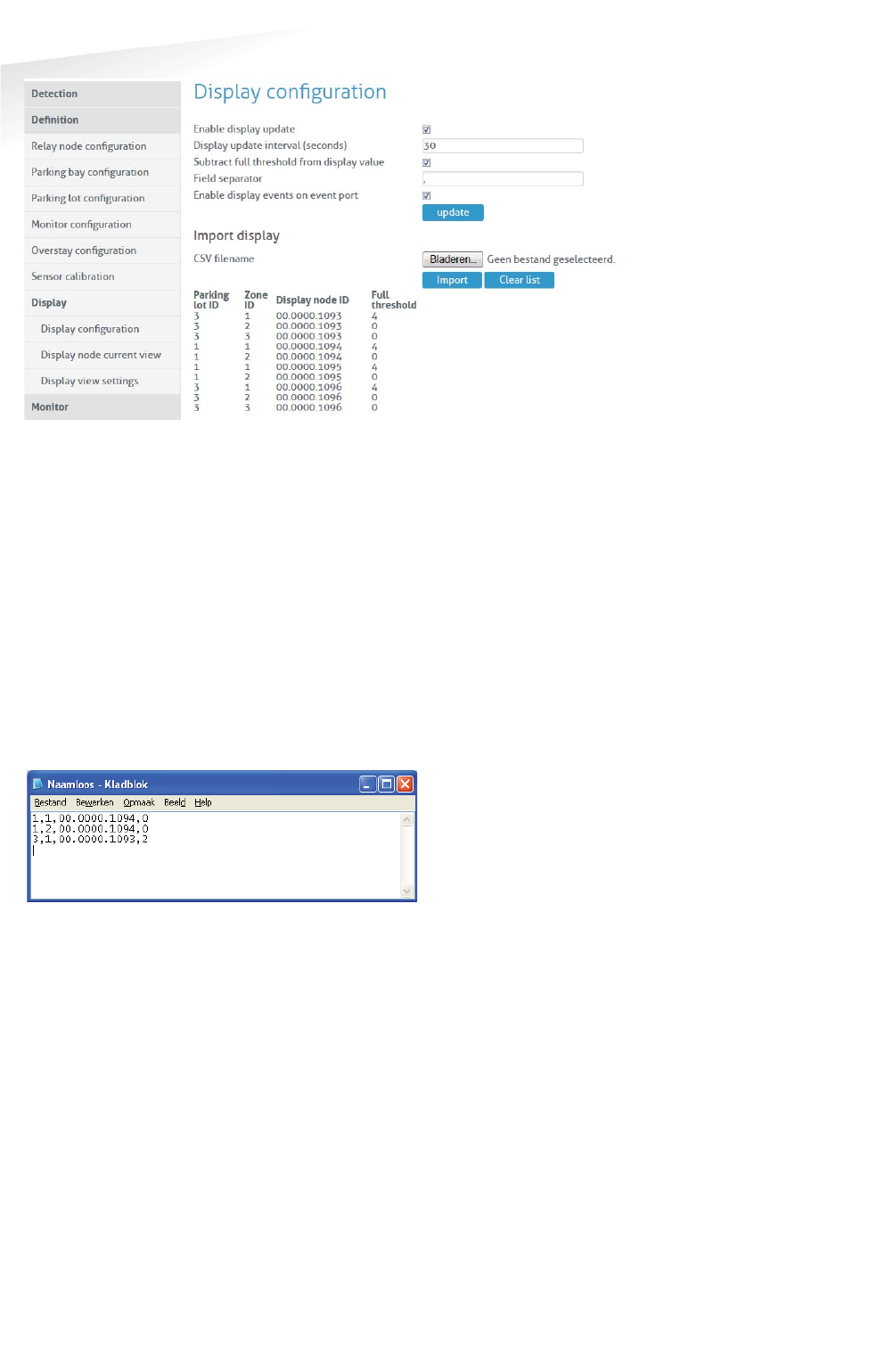
SENSIT SYSTEM | MANUAL
SENSIT Interface Software
80/
111
SE
NS
IT I
nt
er
fa
ce
S
of
tw
ar
e
Figure 69: Display configuration
The display will show the total number of available spaces on all the parking zones
and parking lots it has been assigned to. In case you want to display information on
individual zones, we advise you to allocate one display node to each parking zone.
The display configuration information is imported into the system via a csv-file
(comma separated values). The following information should be entered into the
csv-file separated by a comma (' , ').
x Column 1 Parking lot ID.
x Column 2 Zone ID.
x Column 3 Display node ID.
x Column 4 Full threshold. When less parking places are available, the
display will indicate FULL.
Figure 70: Example display configuration csv-file
Select the csv-file by clicking the 'Browse'-button, then click 'Import' to import the
selected file.
Display Current View
The display current view shows the actual display information per display node.
Display View Settings
The display view settings allow configuring the weekdays and time periods during
which the display information should be updated. This can be used for example in
cases where the display should be off during nighttime.
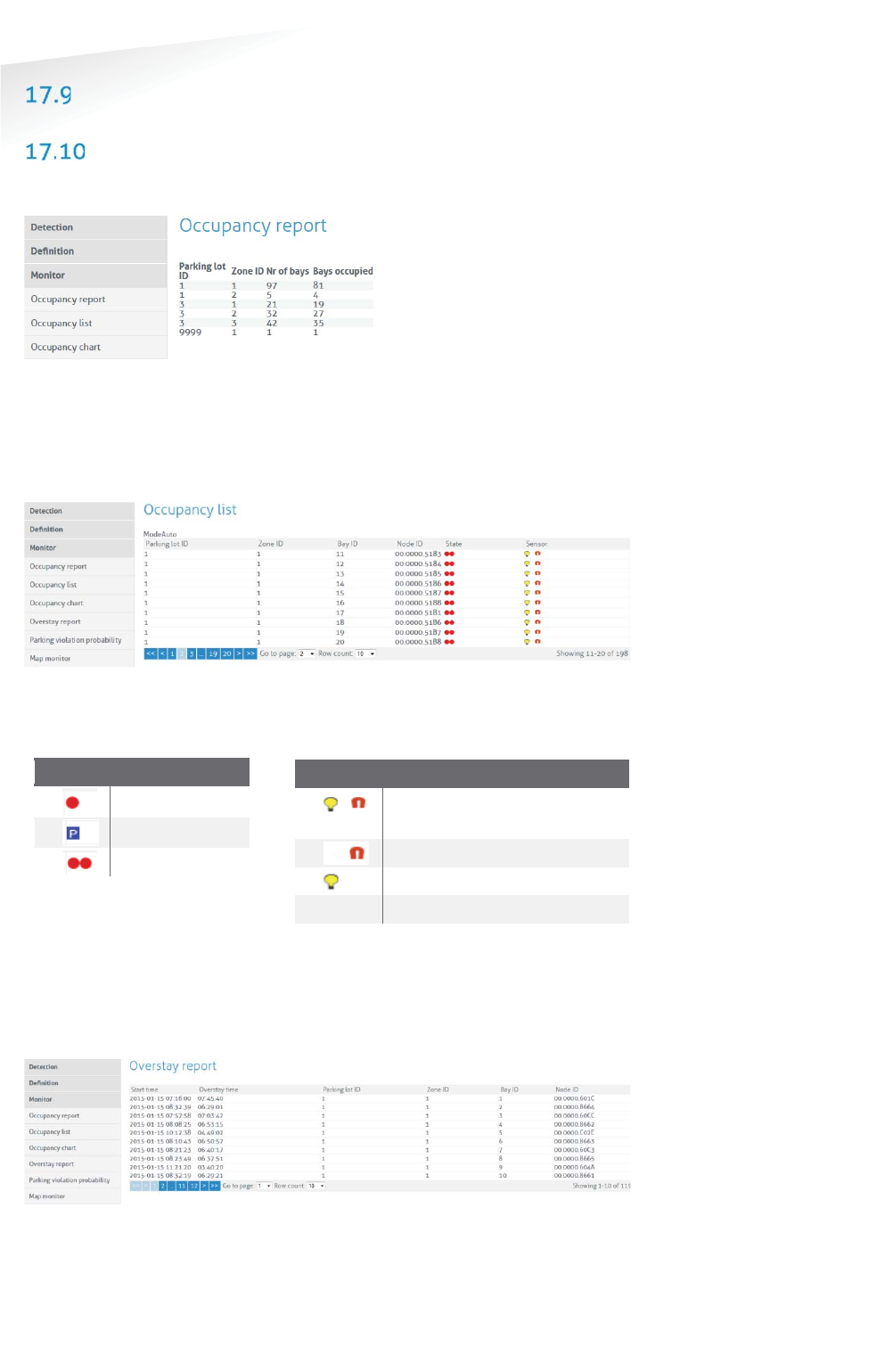
SENSIT SYSTEM | MANUAL
SENSIT Interface Software
81/
111
SE
NS
IT I
nt
er
fa
ce
S
of
tw
ar
e
MONITOR
OCCUPANCY REPORT
The occupancy report displays the actual number of occupied bays in a parking lot.
Figure 71: Occupancy overview
17.10.1 OCCUPANCY LIST
The occupancy list shows the actual occupancy information per parking bay.
Figure 72: Occupancy list
Please find below a small table, which explains the different symbols:
SState
DDescription
Occupied
Free
Overstay
17.10.2 OVERSTAY REPORT
The overstay report shows all the parking bays that currently are in overstay.
Moreover it also visualizes the parking start time for each parking bay.
Figure 73: Overstay report
SSensor
DDescription
Optical and Magnetic
occupied
Magnetic occupied
Optical occupied
Free
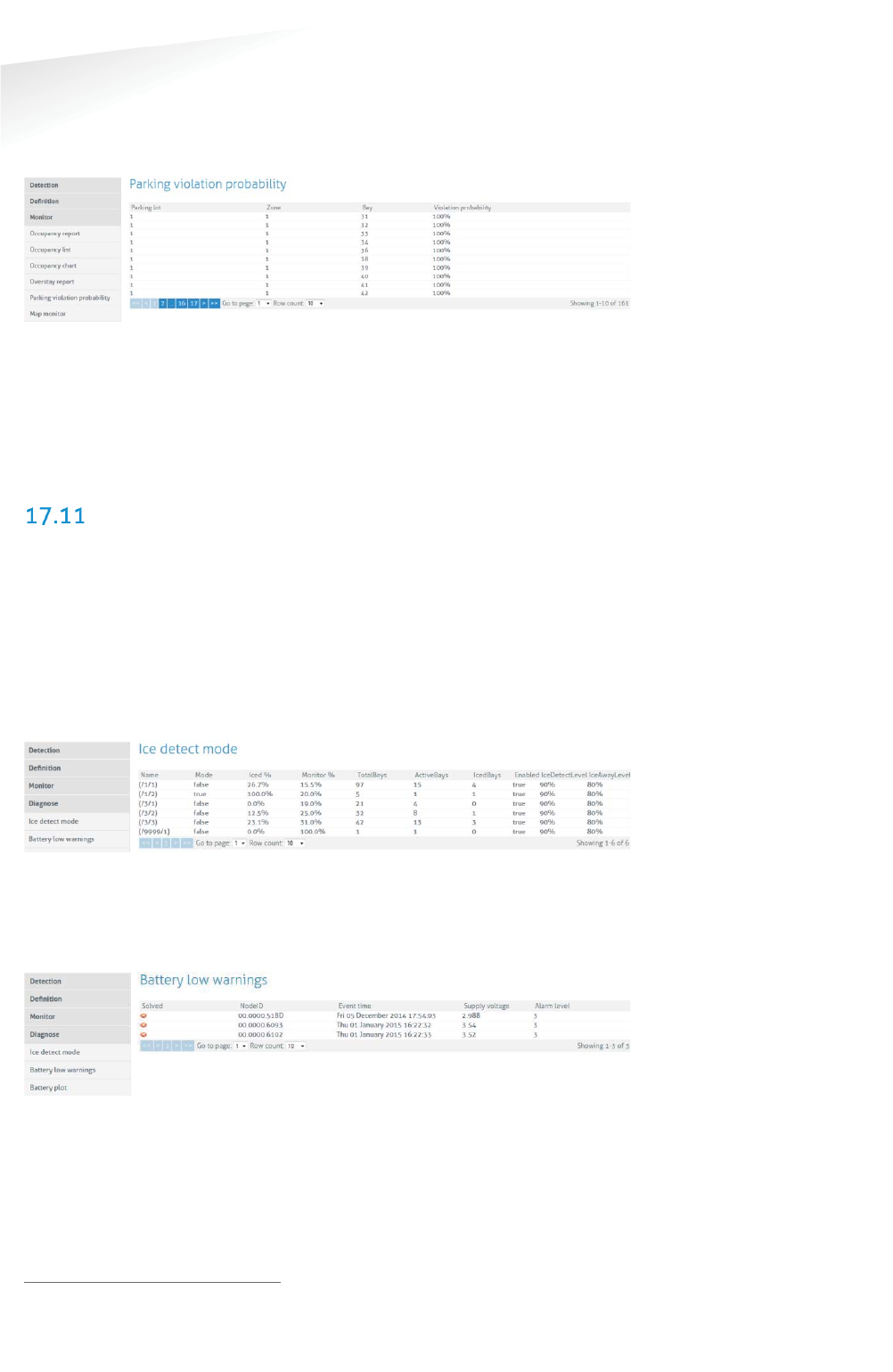
SENSIT SYSTEM | MANUAL
SENSIT Interface Software
82/
111
SE
NS
IT I
nt
er
fa
ce
S
of
tw
ar
e
17.10.3 PARKING VIOLATION PROBABILITY
The parking violations probability overview shows a list of all occupied parking bays
that require a license. The calculated violation probability is shown.
Figure 74: Parking violations overview
Third party applications can pick up items from this table using the documented
SOAP or REST interface. For more information on specific SOAP commands see the
SENSIT Software Integration Developer Guide. The REST API is explained at the left
side under Documentation. Violations that exceed a certain violation probability
threshold can trigger enforcement or more generic follow up activity.
DIAGNOSE
17.11.1 ICE DETECT MODE
Snowfall or ice-forming will obscure the IR sensor. Based on internal sensors1 and
algorithms, the sensor will set a warning bit in the message data indicating possible
snow or ice deposit. Based on this information, coming simultaneously from multiple
sensors at the same parking lot, a global ice detection algorithm running on the SIS
decides whether to use dual or magnetic detection only and switches the Sensor
Select Mode accordingly. In the figure below an example of the automatic global ice
detection situation of the system is shown.
Figure 75: Ice detect mode
17.11.2 BATTERY LOW WARNINGS
In this list all SENSIT with a low battery voltage are mentioned. These warnings show
up whenever the battery voltage of a SENSIT drops below the 3 Volt (Alarm level).
Figure 76: Battery low warnings
1 SENSIT Dual Technology sensors features a.o. a temperature sensor.
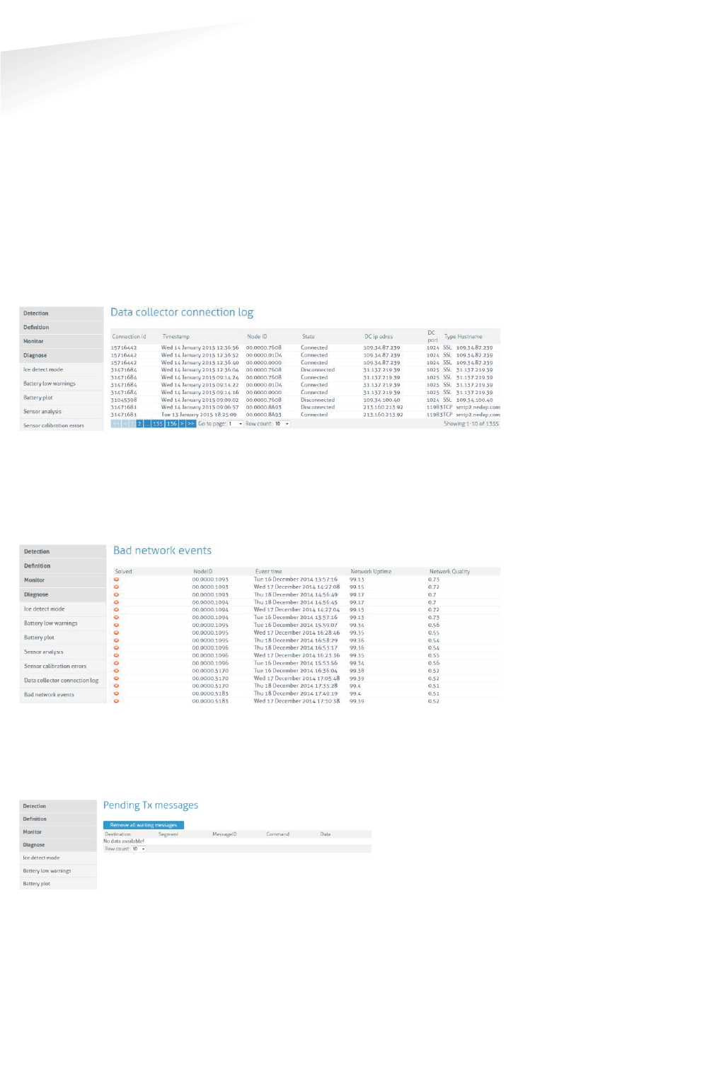
SENSIT SYSTEM | MANUAL
SENSIT Interface Software
83/
111
SE
NS
IT I
nt
er
fa
ce
S
of
tw
ar
e
17.11.3 SENSOR CALIBRATION ERRORS
This screen indicates the SENSIT nodes that do not transmit any state event
messages. For example, an event is created when a vehicle enters the parking bay
and a difference in the magnetic field is has been detected. When the difference in
the magnetic field does not result in a state change event, in other words no change
in the occupancy, this might indicate that the SENSIT has not properly been
calibrated. The screen indicates the number of events received from a specific
SENSIT without a state change.
17.11.4 GATEWAY CONNECTION LOG
This screen shows a list of all connects and disconnects of the SENSIT Gateways in
the system.
Figure 77: SENSIT sensor analysis
17.11.5 BAD NETWORK EVENTS
This table shows all events that a SENSIT generates, when it detects possible
problems in the wireless communication.
Figure 78: Bad network events screen
17.11.6 PENDING TX MESSAGES
This table show all message in the transmit queue.
Figure 79: Pending TX messages screen
17.11.7 PENDING RX MESSAGES
This table show all message in the receive queue.
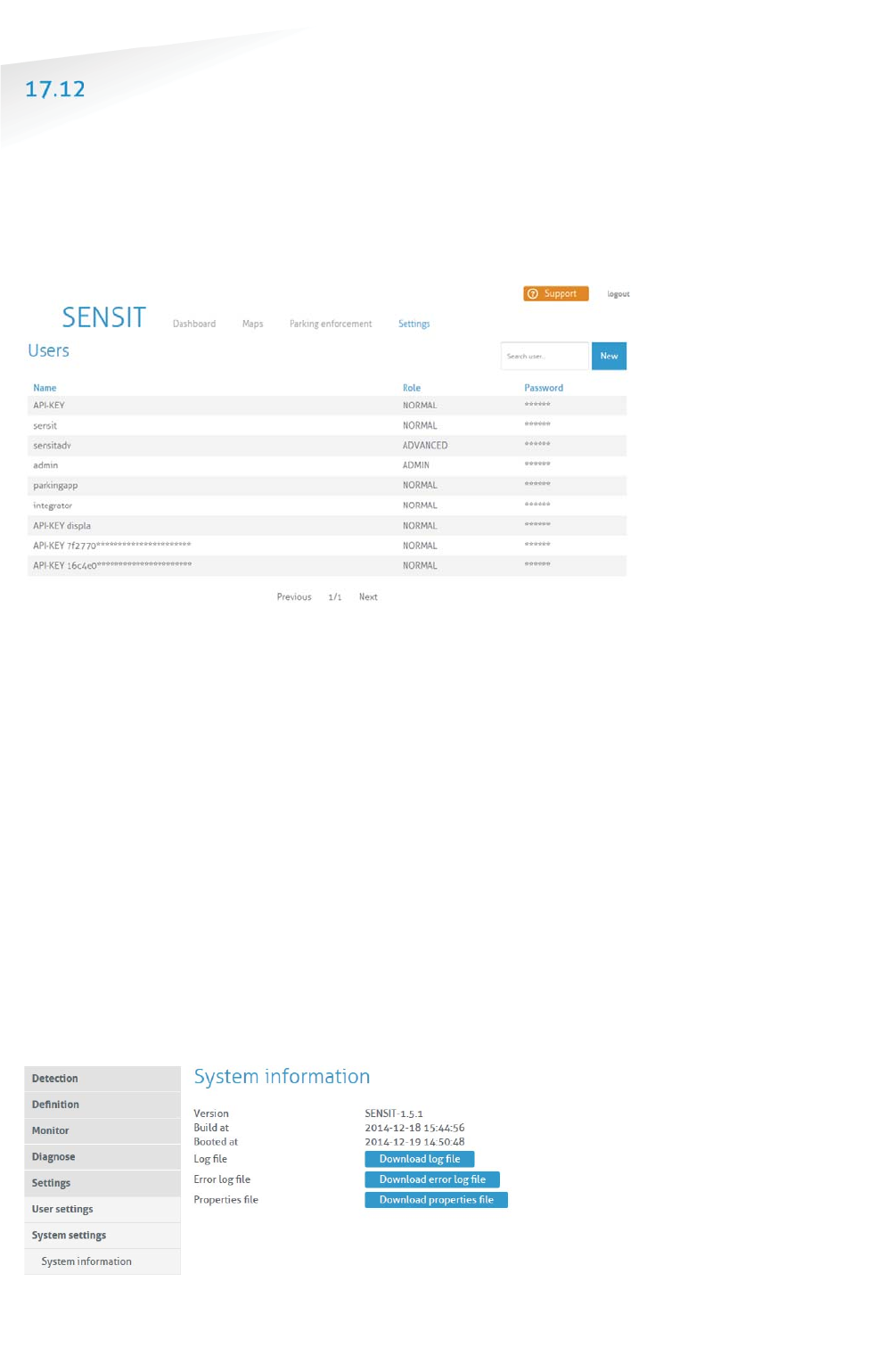
SENSIT SYSTEM | MANUAL
SENSIT Interface Software
84/
111
SE
NS
IT I
nt
er
fa
ce
S
of
tw
ar
e
SETTINGS
17.12.1 USER SETTINGS
Change Password
In this screen the password of the current logged in user can be changed.
User administration
In this screen new users can be created, deleted or changed.
Figure 80: User administration screen
17.12.2 SYSTEM SETTINGS
System Information
The system information menu offers the user the possibility to download log files
and to change system specific settings.
Download log file
This setting is used to provide remote support. The log file contains all the
information required for Nedap's engineers to analyze system information.
Download error log file
This setting is used to provide remote support. The log file contains all the
information required for Nedap's engineers to analyze system information.
Download properties file
The properties file contains all the system settings. This file can be used for support
purposes to verify the system.
Figure 81: System info
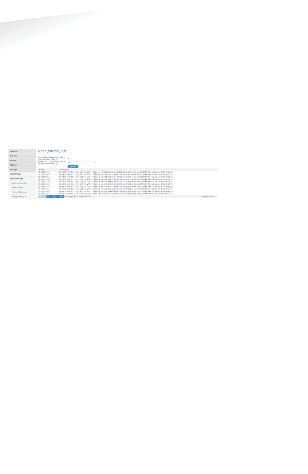
SENSIT SYSTEM | MANUAL
SENSIT Interface Software
85/1
11
SE
NS
IT I
nt
er
fa
ce
S
of
tw
ar
e
System Reboot
Click the 'Reboot'-button to reboot the SENSIT Server.
Time Configuration
Configure here the time zone settings of the SENSIT Server.
Node Gateway List
Here you can activate if a message for a specific SENSIT is only transmitted via the
SENSIT Gateway(s) in the Gateway list. In this way only the involved SENSIT
Gateway(s) are transmitting the message into the (local) Wireless SENSIT Network
and not too all SENSIT Gateways available in system. If a specific SENSIT doesn’t
communicate for in this case 24 hours the Gateway list will be clear for this SENSIT
and a message for this specific SENSIT will be transmitted via all available SENSIT
Gateways.
Figure 82: Node gateway list screen
Local Configuration
Store events in database
Select this option to store events in the database of the SENSIT Server. Normally this
option should be selected.
Recover lost messages
The event messages have a sequence number. With this sequence number, the
SENSIT Server can determine if messages were lost. When this happens the SENSIT
Server can ask the SENSIT to resend these lost messages. Enable the checkbox if this
is desired.
Message recovery retry time
Message recovery retry time (in minutes) is the repeat time the system will search
for events it has not yet received. The search will be repeated after the set time.
Restore received messages at startup
Select this option if you want to restore events at SENSIT Server startup.
Number of lost messages to recover at startup
You can select the maximum number of messages you want to recover per node
(max. 32 messages).

SENSIT SYSTEM | MANUAL
SENSIT Interface Software
86/
111
SE
NS
IT I
nt
er
fa
ce
S
of
tw
ar
e
Sensor select mode
SENSIT Dual Technology sensors feature an infrared sensor and a triple axis
magnetometer. Both technologies work together to provide reliable and accurate
vehicle detection. There are different modes of operation impacting how the status
is calculated. For each individual sensor, the system tracks the actual status of the IR
and magnetic sensor. Based on this information, the “calculated state” of the sensor
(i.e. “free” or “occupied”) is determined. The “Sensor Select Mode” setting
determines how the calculation is made. There are five options for the “Sensor
Select Mode”, see table below.
SSettings
DDescription
Auto Sensor is automatically selected using intelligent
algorithms (Recommended setting).
Magnetic
Only the magnetic sensor is used.
Optical
Only the optical (infrared) sensor is used.
MagneticANDOptical
The
parking bay is occupied when both sensor detect the
vehicle (magnetic + optical).
MagneticOROptical
The parking bay is occupied when at least 1 of the
sensors detect the vehicle.
In auto mode, an algorithm at sensor level monitors the operation and decides which
sensor is most accurate. While the IR sensor is generally leading, the sensor alters
the leading technology in case of incongruity (i.e. when the behavior of both
technologies deviates from what is standard or expected). For example the optical
sensor indicates a continuously occupied bay and the magnetic sensor senses
alternating presence of a vehicle above the SENSIT sensor. After a number of
mismatches (by default 10 consecutive mismatches) between the continuous
occupied optical sensor and the magnetic sensor, the magnetometer will become
leading. As soon as the optical sensor is clean, the sensor will automatically render
IR detection leading.
Calibrate error after .. magnetic events when occupied
The SENSIT Server registers when both sensors of a SENSIT-IR disagree about the
occupancy state. In automatic mode, the optical sensor has a higher priority.
However when the optical sensor is dirty, this will have a negative result on the
accuracy. This setting will generate a Calibration error when the optical sensor
remains occupied while the magnetic sensor registered state changes several times.
See also chapter 17.11.3.
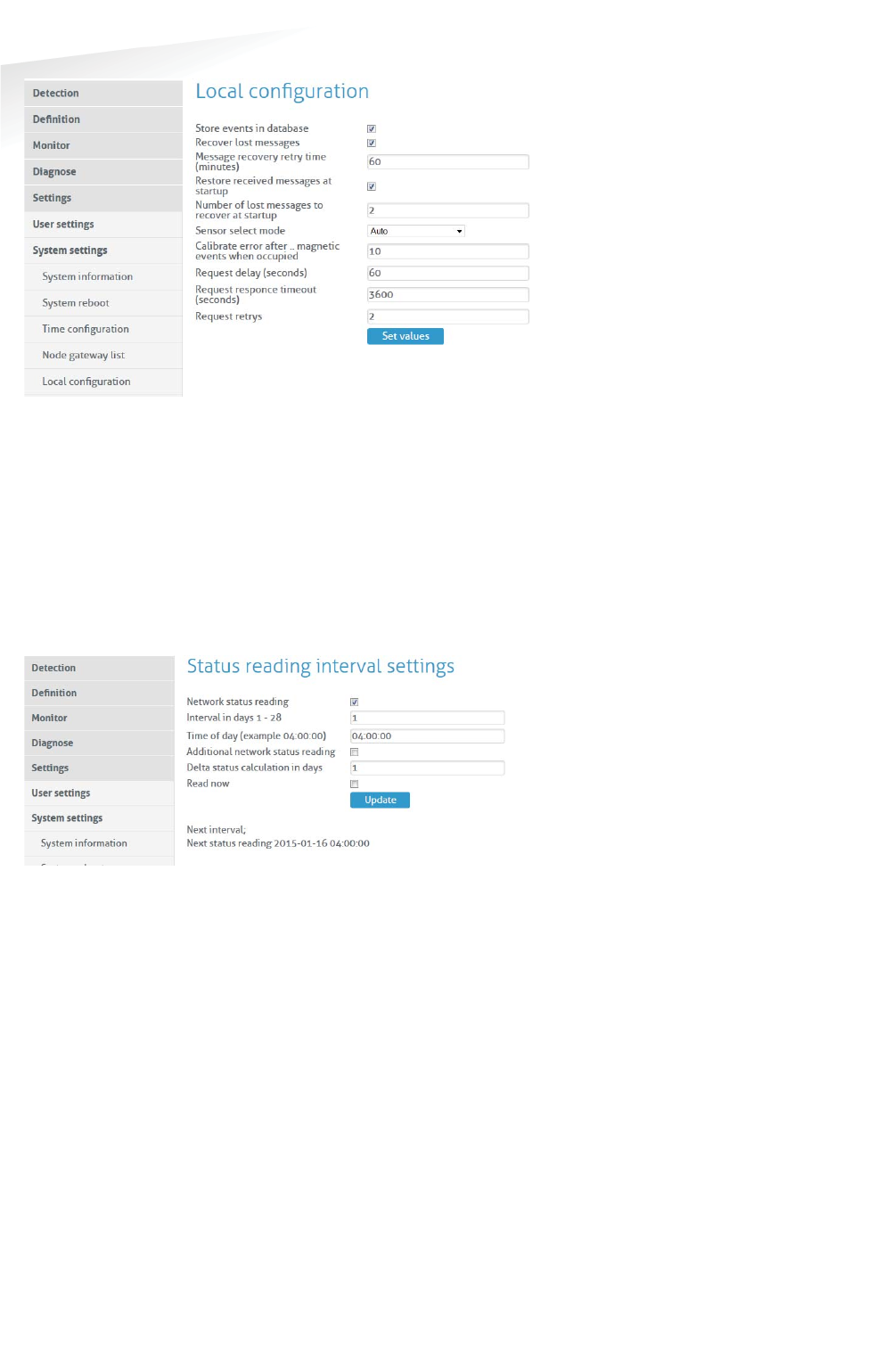
SENSIT SYSTEM | MANUAL
SENSIT Interface Software
87/
111
SE
NS
IT I
nt
er
fa
ce
S
of
tw
ar
e
Figure 83: SENSIT local configuration
Active Http Sessions
In this screen you can see all user logged in to the web-server. All active open web
sessions are shown.
Status Reading Interval Settings
Enable the status reading to make the SENSIT Server request the network
performance statistical counters for every node. Preferably this is done at night
when there are relatively few vehicle movements. The status reading can be shown
in the Map, when selecting the Network Uptime Mode.
Figure 84: Status reading
17.12.3 EXPERT SETTINGS
Console
The Console menu allows you to directly transmit commands to the SENSIT network.
It is not recommended to experiment with the functionalities in this window unless
instructed to you by Nedap technical support engineers.
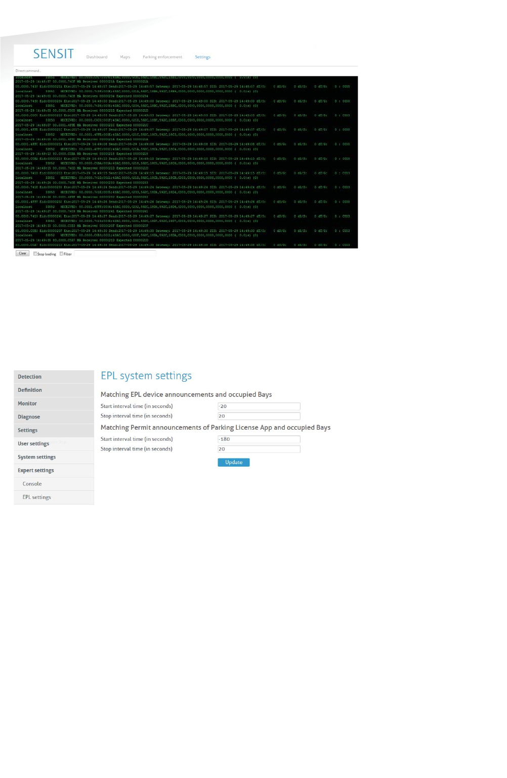
SENSIT SYSTEM | MANUAL
SENSIT Interface Software
88/
111
SE
NS
IT I
nt
er
fa
ce
S
of
tw
ar
e
Figure 85: Console
EPL settings
The matching time window is adjustable and can be set differently for the SENSIT
EPL and the EPL App. This matching time window specifies the allowed time
uncertainty of an EPL or EPL App. Based on this value an EPL or EPL App is included
or excluded in the matching algorithm.
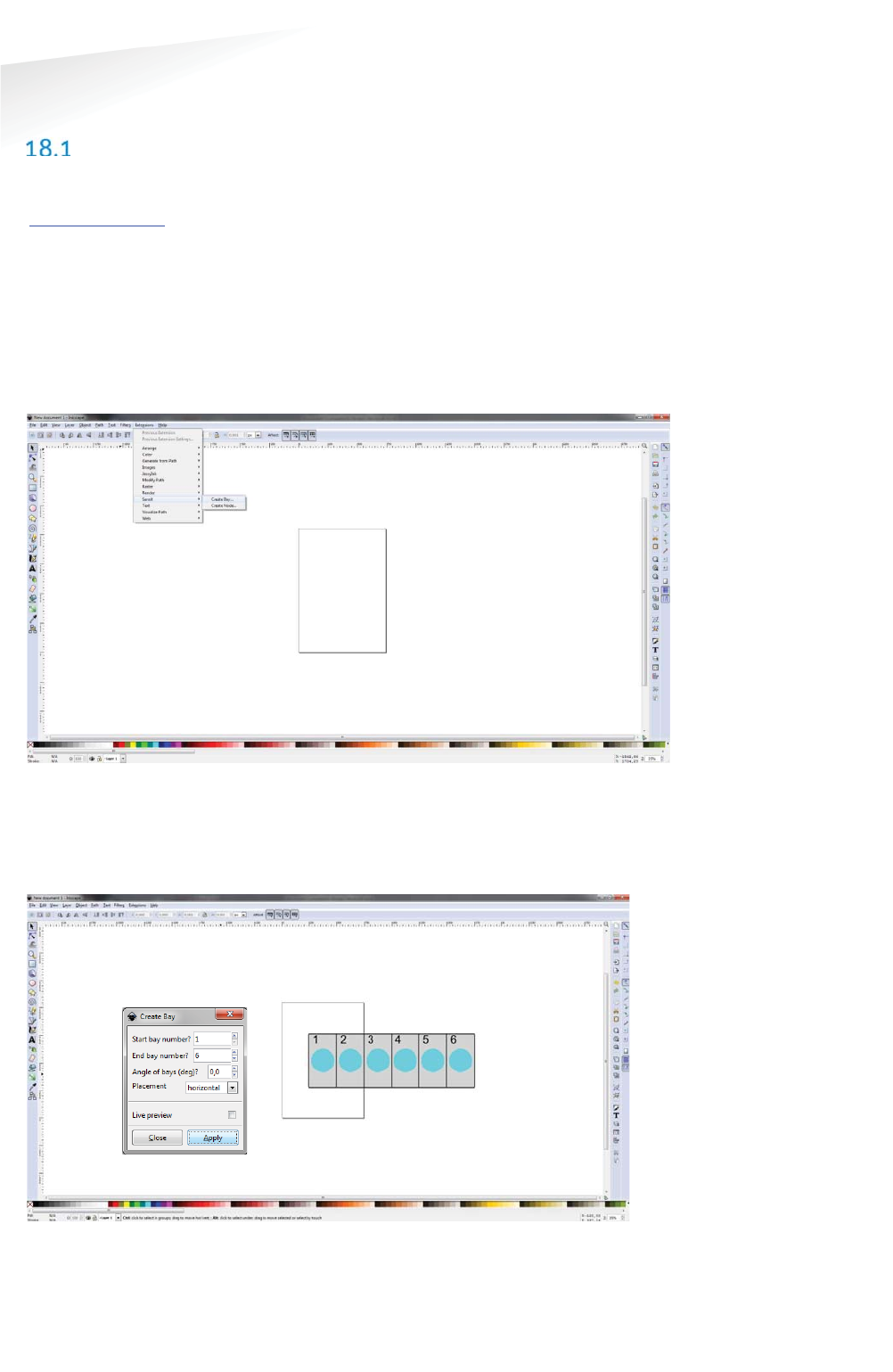
SENSIT SYSTEM | MANUAL
Advance Configuration
89/
111
Advance Con
f
i
g
uratio
n
18 ADVANCE CONFIGURATION
INKSCAPE
The maps for the Monitor map at the SIS must be in a Scalable Vector Graphic image.
These SVG-file images can be created with an open-sources program Inkscape
(http://inkscape.org). Nedap has an extension available for Inkscape that should be
used to define where the parking bays, Relay Nodes and Gateways are located on
the map.
After installing Inkscape and the Nedap Inkscape extensions the program can be
started. By selecting Extensions -> SENSIT -> Create Bay… bays can be added to the
drawing and by selecting Extensions -> SENSIT -> Create Node… nodes (Relay nodes
or SENSIT Gateways) can be added to the drawing. See also the figure below.
Figure 86: Inkscape SENSIT extensions
After selecting the Create bay… option a pop-up window appears, see Figure 87
below. You can add bays to the drawing. In this way a simple representation of the
parking lot can be created. In this example 6 bays (bay number 1 to 6) are created.
Figure 87: Inkscape, Create Bay
The same for adding Relay Nodes and SENSIT Gateway. By selecting Extensions ->
SENSIT -> Create Node… the Create Node pop-up window appears. In the example
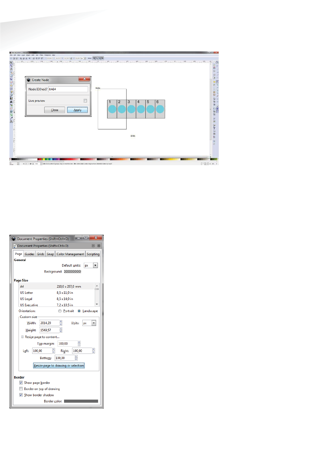
SENSIT SYSTEM | MANUAL
Advance Configuration
90/
111
Advance Con
f
i
g
uratio
n
below a SENSIT Gateway with ID-number 8AB4 and a Relay Node with ID-number
8A9B is created and place at the right location in the map.
Figure 88: Inkscape, Create Node
When the drawing is finished the next step is to scale the drawing correctly so all
bays, Relay Nodes and SENSIT Gateways are nicely places in the map. First select al
objects, this can be done easily with Ctrl + A. Select: File -> Document Properties…
and then in Custom size, Resize page to content… add some top, bottom left and
right margin to the page and select the button Resize page to drawing or selection.
See also Figure 89 below.
Figure 89: Inkscape, Resize page
Further make sure you remove the viewBox item via the XML editor. The XML-editor
can be found via the menu Edit -> XML Editor… the viewBox item can be deleted
with the marked button, see screenshot below.
Note
Make sure the units i
s in
pixels (px) otherwise the
scaling in the monitor map
might not work properly.
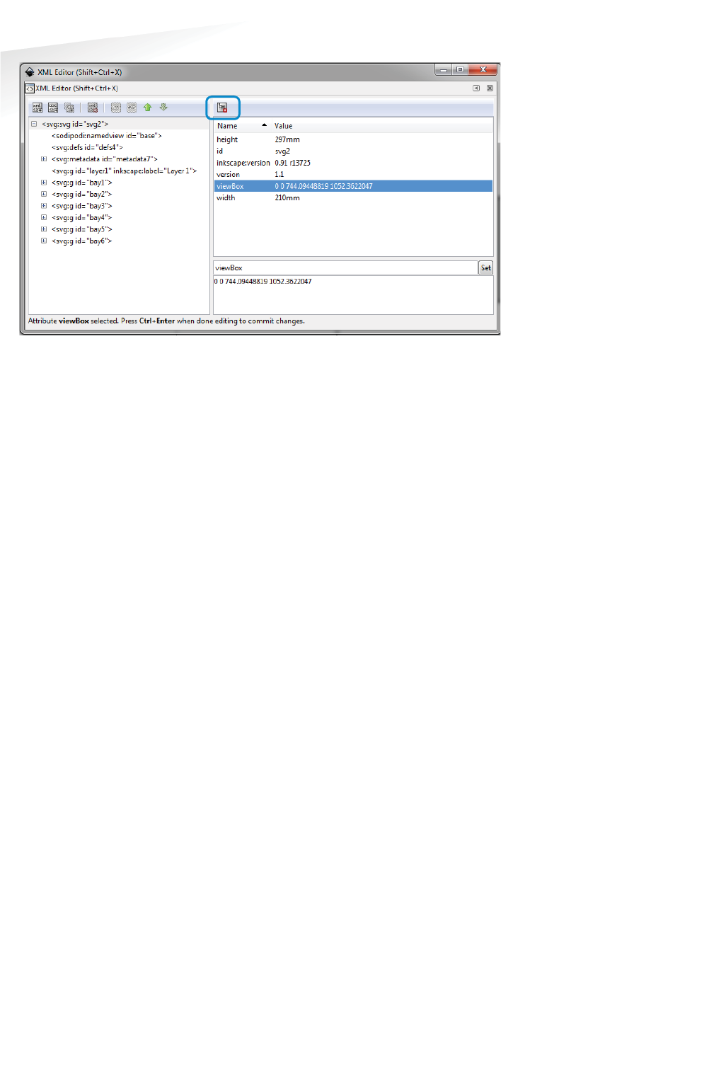
SENSIT SYSTEM | MANUAL
Advance Configuration
91/
111
Advance Con
f
i
g
uratio
n
Figure 90: Inkscape, remove viewBox
After resizing the page and removing of the viewBox the file can be saved as a SVG-
file make sure you don’t use spaces in the filename and after that uploaded to the
SIS as described in chapter 17.8.4.

SENSIT SYSTEM | MANUAL
Frequently Asked Questions
92/
111
Frequentl
y
Asked Question
s
19 FREQUENTLY ASKED QUESTIONS
GENERAL
W
What types of SENSIT sensors are available and what is the difference?
There are 3 different types of SENSIT sensors available:
1 SENSIT IR - Magnetic and optical sensor suitable to be built-into the floor of
each parking space.
2 SENSIT Flush Mount - Magnetic sensor suitable to be built-into the floor of
each parking space.
3 SENSIT Surface Mount - Magnetic and optical sensor for mounting onto the
floor of a parking space
What is the accuracy of the SENSIT Flush Mount?
The magnetic sensor can achieve an accuracy of 95%.
What is the accuracy of the SENSIT IR and SENSIT Surface Mount?
The combination of the magnetic and optical sensor has an average accuracy of
above 98%.
How scalable is the SENSIT system?
The SENSIT system is quite scalable. The theoretical maximum number of SENSIT
nodes in one network is about 65000. In general, large installation need to be
divided into smaller sub-networks (segments), which makes it better manageable
and easier to understand. Sites that have more than 500 sensors or more than 15
Relay Nodes need segmentation. Please contact your Nedap account manager.
What is the temperature range for the SENSIT and SENSIT IR?
The temperature range for both SENSIT as well SENSIT IR is -40°C to 85°C [-40 to
185°F]. Temperatures below -30°C [-22°F] might affect accuracy of the magnetic
sensor. The accuracy on the optical sensor remains unchanged.
How does the dual sensor technology principle work ?
The optical sensor is based on IR reflection, using a modulated high power IR LED
transmitter and a sensitive IR diode as receiver. The IR radiation is reflected by the
bottom of a vehicle and captured by the IR diode.
The 3D magnetometer senses the variation in the earth magnetic field when a
vehicle stops above the sensor. The magnetic status of the SENSIT sensor switches
to “occupied” if at least one axis (X, Y or Z) measures a deviation of more than
50mGauss compared to the stored calibration vector.
The IR sensor is potentially more accurate but sensitive to dirt, snow and ice. The
triple axis magnetometer however is not influenced by dirt, snow or ice. By default,
the sensor checks its IR sensor and magnetometer status every second.
Both technologies work together to provide reliable and accurate vehicle detection.
There are different modes of operation impacting how the status is calculated.
For each individual sensor, the system tracks the actual status of the IR and magnetic
sensor. Based on this information, the “calculated state” of the sensor (i.e. “free” or
“occupied”) is determined.
How does the energy efficient Wireless SENSIT Network work?
The medium access protocol is based upon time division multiple access (TDMA).
Time is divided into time slots, which (Relay) nodes can use to transfer data without
having to content for the medium or having to deal with energy wasting collisions of
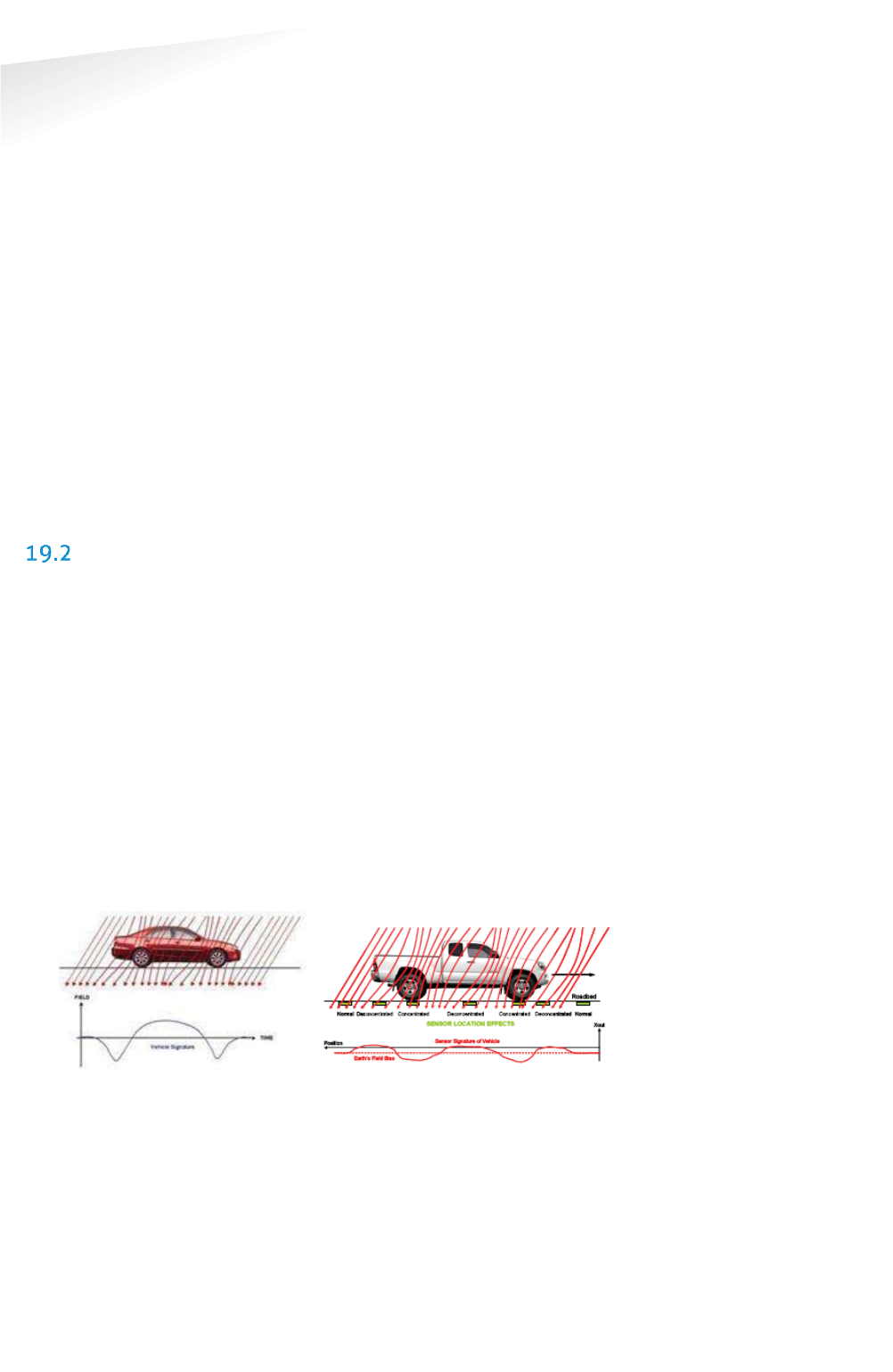
SENSIT SYSTEM | MANUAL
Frequently Asked Questions
93/
111
Frequentl
y
Asked Q
ue
st
io
ns
transmissions. After the frame length, which consists of 16 time slots, the (Relay)
node again has a period of time reserved for it. We have parameterized the duration
of a time slot and the number of time slots. The default timeslot is 100ms and the
number of timeslots in a frame is 16. In the US the system uses also Frequency Hop
Spread Spectrum (FHSS); a pseudo random frequency hopping scheme every
timeslot the SENSIT also changes the frequency. In this way the devices comply with
FCC regulations.
If a SENSIT sensor decides to transmit a messages it asks the first Relay Node within
reach if it is allowed to transmit a message to this Relay Node, if allowed the Relay
Node will receive the message from the SENSIT and retransmits this message to the
next Relay Node or directly to the SENSIT Gateway.
C
Can a SENSIT sensor been used to replace a loop detector?
The SENSIT sensor is designed to detect a changes in either optical or earth
magnetic field. A continuous flow of traffic would generate a constant status change.
Moreover since the system is based on wireless communication, communication is
slower compared to hard wired loop. We therefore do not advise to use the SENSIT
sensor to replace safety loops for critical applications.
MAGNETIC SENSOR
Is the magnetic sensor influenced by snow or ice?
We have tested the system with about 15 cm (5.9 in) of snow during multiple tests.
Snow did not affect the accuracy of the magnetic performance.
Is the magnetic sensor influenced by dirt?
The magnetic sensor is not influenced by dirt like sand, mud or leafs.
How quickly does the magnetic sensor in the node react to a change in status?
Default the magnetic sensor checks its status change every second.
Can the magnetic sensor ‘see’ the magnetic difference between a car and truck?
In a static parking application a SENSIT sensor cannot observe a difference between
a small vehicle and a large truck. The variation in the earth magnetic field changes
under a car or truck does not depend on the height of the vehicle but on where a car
or truck stops. See also the image below to clarify this in more details.
Image 1: Vehicle & earth magnetic field Image 2: Truck & earth magnetic field
How does the SENSIT sensor detect a car and changes the magnetic status from free
into occupied?
The magnetic status of the SENSIT sensor has changed if at any axis (X, Y, and
Z) changes more than 50mGauss compared to the stored calibration vector.
Normally the earth magnetic field vector is about 500mGauss. This can vary
allot from place to place. In order to set the SENSIT sensor to local earth magnetic
field we advise to calibrate the sensors.
Note
Setting or changing the
overdrive filter affects
reaction time.
Note
Default the overdrive filter
is set at 8 seconds.

SENSIT SYSTEM | MANUAL
Frequently Asked Questions
94/
111
Frequentl
y
Asked Question
s
H
How can I avoid a vehicle driving over the SENSIT sensor to trigger a status change
event message?
When a vehicle is driving over a or multiple SENSIT sensors to reach the final parking
bay the overdriven SENSIT sensors will transmit an occupied and free event
message. If the overdrive filter isn’t set. By default the overdrive filter is set to
eliminate these kinds of messages. After setting the overdrive filter the SENSIT
sensor will only transmit a status change event if the SENSIT sensor has been
occupied of free for the set time.
19.2.1 CALIBRATION
Why calibrate?
The local earth magnetic field vector (value and direction) at an installed SENSIT
sensor depends on the orientation of the SENSIT sensor, the amount of metal in the
neighborhood and the location on the earth. When the calibration is done this local
earth magnetic field vector is stored. It is therefore necessary to always calibrate the
sensors.
How can I see if the calibration is done correctly?
When connecting the SENSIT Gateway to the SIS, the SIS software will indicate
calibration errors for sensors which are not calibrated. In the Sensor data message
there is a magnetic un-calibrated bit which warns you if the SENSIT sensor thinks it is
not calibrated well.
Does the parking need to be fully empty to calibrate the SENSIT sensors?
Yes, preferably the parking needs to be fully empty in order to calibrate the SENSIT
sensors. If you need to calibrate a single parking bay it is sufficient if only all
neighboring bays are empty. Easy calibration can be realized through the SIS
website.
My parking lot is hardly ever empty, how can I calibrate the sensors?
If it is not possible to calibrate the entire parking lot, we suggest calibrating the
parking lot section by section directly after installation of the SENSIT’s.
OPTICAL SENSOR
What is the measuring interval of the optical sensor?
The optical sensors periodically checks once per second if there is a status change.
(You can extend battery life by setting slowing measuring intervals.)
Why is the SENSIT IR featured with two detection technologies?
Double detection technology provides a higher accuracy rate. Each detection
technology has its advantages and disadvantages. The combination of both ensures
a reliable detection product in all circumstances and differentiates our product from
any other product in the market. The optical sensor is potentially more accurate but
sensitive for dirt, snow and ice. We specify an average accuracy of 95% for the
SENSIT Flush Mount (only magnet) and 98% for the SENSIT IR (magnet and optical).
In cases of snow or the optical sensor being covered the unit will automatically
switch to earth magnetic field detection.
Which sensor is making the decision; occupied or free?
In most cases the optical sensor is indicating the final status. The algorithm inside
the SENSIT sensor decides which type of sensor to trust. Of course you can ignore
this and decide for yourself which sensor to use, because the state of the magnetic
and the optical sensor is available.

SENSIT SYSTEM | MANUAL
Frequently Asked Questions
95/
111
Frequentl
y
Asked Question
s
W
What is the detection principal of the optical sensor?
The optical sensor is based on IR reflection. We are using a high power IR LED as
transmitter and a sensitive IR diode as receiver. The IR radiation is reflected by the
bottom of a car or truck and is received by the IR receiving diode. This means the
bay is occupied.
Is the optical sensor influenced by snow or ice?
Yes the optical sensor detects based on something covering the sensor. In case the
sensor is covered with snow or frost it will be seen as occupied. In the sensor data
message there is a bit that warns you for possible ice on the SENSIT sensor. As the
SENSIT IR is featured with dual sensing technology you can also decide to switch the
sensors to magnetic detection in winter periods using the SIS software. Beside that
on the SIS there is a global ice detection algorithm implemented which
automatically can decide to switch to the magnetic sensor in case of ice or snow. See
chapter 17.11.1 for more information.
Is the optical sensor influenced by dirt?
The optical sensor is designed to not easily be covered with little amounts of dust or
sand and therefore this will not affect the performance. Larger amounts of dirt will
disable the optical sensor. At an outdoor parking-lot, the self-cleaning surface of the
SENSIT IR ensures that dirt is automatically flushed of and does not easily attach to
the SENSIT IR. This makes it a very usable and practical system. The sites world-wide
installed outdoors have since installation (in about 2006) never been cleaned.
What happens in case of sandstorms, when the optical sensor is covered?
When the optical is covered with sand the sensor cannot detect reflections of a
vehicle that parks over the SENSIT sensor. So the optical sensor will indicate a free
bay, the secondary (magnetic) sensor will detect the movement of the different cars
above the SENSIT sensor. After a few (default: 10) mismatches between the
continuous occupied optical sensor and the magnetic sensor the final status will be
indicated by the magnetic sensor. As soon as the optical sensor is clean, the SENSIT
sensor will automatically switch back to optical detection again.
Is the SENSIT IR affected by direct sun light?
Normally the optical IR sensor is not affected by sunlight. Only at locations close to
the equator when the sun is directly above the SENSIT IR the optical sensor can give
an overexposure alert, which will indicate a free bay.
19.3.1 CALIBRATION
What is the maximum range of the optical sensor?
The IR reflection depends very much on the reflection coefficient of surface it
radiates at. Ceilings of over 3 meters (9 feet) are seen by the optical sensor. You can
set the sensitivity of the optical sensor when applying the sensors for indoor
applications.
Can the optical sensor been used indoors?
The optical sensor can be used indoors, for this the IR transmitting power needs to
be adjusted (calibrated) to avoid the unit from detecting the ceiling.
MORE INFORMATION SENSIT AND MOUNTING
What filling material should I use?
The best way to fix the SENSIT sensors into the floor of the parking space is using

SENSIT SYSTEM | MANUAL
Frequently Asked Questions
96/
111
Frequentl
y
Asked Question
s
rapid mortar (eg.TM 5R). Ensure to fixate the SENSIT sensors during curing time, to
avoid them from floating in the mortar. When you want to use another brand of
rapid mortal please sent us the datasheet so we can analyze this and advise you on
use.
I
Is a SENSIT IR snow plough resistant?
When using the SENSIT IR in environments with snowy weather conditions, we
advise to set a tolerance on the snow plough of 2 cm [0.78 in] to ensure the top of
the sensor is not damaged by the snow plough. The SENSIT IR is not fully snow
plough resistant; however it can withstand a few incidental hits. The SENSIT Flush
Mount is snow plough resistant and can be used in areas with frequent snow
conditions, at the cost of a bit lower accuracy.

SENSIT SYSTEM | MANUAL
Frequently Asked Questions
97/
111
Frequentl
y
Asked Question
s
INSTALLATION
H
How much time does an installation take?
Based on installation experiences, an estimation of the needed man hours for
installing about 100 SENSIT IR is provided below.
Task
Description
Man hours
Preparation Making a simple drawing of the
parking lot and upload it to the SIM
2
Installation
SENSIT IR
Determine location of every SENSIT IR,
drilling holes and fixing them
8
Installation Relay
Nodes
Mounting the Relay Nodes 1
Testing
Making a csv file, upload it to the SIS
and verify if all SENSIT sensors are
online
4
How do I start?
Please read chapter 3 of this document for a 4-step installation plan.
BATTERY LIFE
What is the battery life?
The battery life of the SENSIT sensor in a good performing network is 5 years this
with default settings of the network and the measurement intervals.
Can batteries be exchanged?
The SENSIT sensors are fully sealed to ensure reliable operation in the outdoor
environment and to avoid any water leakage to the electronics. The batteries cannot
be replaced, as this would create water leakage and unreliable operation. The
SENSIT sensor needs to be replaced after end of battery life. The batteries of the
Relay Node 2G can be replaced, see chapter 10.7.
Can I extend battery life of the SENSIT sensor by adjusting communication settings?
Yes you can extend battery life by adjusting the communication settings. Default the
SENSIT sensors are set to 16 timeslots. This communication setting will realize a
battery life time of 5 years and will achieve a good latency (fast and reliable
communication network). For applications where slower communication (more
latency) is allowed 32 timeslots is recommended to extend battery life time.
Installations using over 15 Relay Nodes should also be set to 32 time slots.
How can I change the communication settings to extend battery life?
Please consult Nedap how to change the communication settings if your application
allows slower communication or if your application needs more than 15 Relay
Nodes.
How do we know if a SENSIT sensor runs out of batteries?
The battery voltages will be requested by the SENSIT Interface Server on a regular
basis. The SIS will display an icon in the node presence list in the SIS if the battery is
low or almost empty. See chapter 17.11.2 and chapter E
Error! Reference source not
ound.
for more information.
If I keep the product in stock for some time, do the batteries run down?
When shipped the units are in stock/transport mode to save battery life. That is why
Note
A network uptime below
99% will reduce the battery
life significantly.

SENSIT SYSTEM | MANUAL
Frequently Asked Questions
98/
111
Frequentl
y
Asked Question
s
you need to swipe the SENSIT sensors with a reset magnet to get them out of stock
mode. In stock/transport mode the SENSIT sensors hardly use any power. In this way
you can have a SENSIT sensor in stock for e.g. a year without influencing the final
battery life.
RELAY NODES
W
What is a Relay Node?
A Relay node consists of a SENSIT configured in an active role and a Relay Node
mounting set. The mounting set allows for easy mounting of the Relay node onto a
lamppost. The Relay node is a normal SENSIT but configured differently, a Relay
Node has a more active role in the wireless network compared to a SENSIT. That is
why we call a Relay Node an active node and a SENSIT a passive node. The
continuous transmitting and receiving of an active node consumes more power than
a passive node who is only listening to a few active nodes to stay synchronized and
to receive incoming messages. The battery life of the Relay Node will be about 2 to
3 years. The advantage is that a Relay Node is still completely wireless and does not
require any power or communication cabling.
What is a Relay Node 2G?
A Relay node 2G is a dedicated product for relaying message from the SENSIT
sensors to the SENSIT Gateway. The Relay Node 2G has an active role and in the
Wireless SENSIT Network. The battery lifetime of the Relay Node 2G is similar as the
lifetime of the SENSIT sensors. The Relay Node 2G is wireless and does not require
any power or communication cabling.
Why are Relay Nodes required?
Relay nodes are required to ensure a faster communication path to the SENSIT
Gateways, a more robust network and less energy consumption. Relay Nodes are
required to ensure that SENSIT sensors positioned in the area can communicate
directly via the Relay Node back to the central system. If each SENSIT sensor would
need to communicate via the other SENSIT sensors installed in the floor, more
communication ‘hops’ are needed. This will cause a slower communicating network,
with a higher chance of missing a message and higher energy consumption.
How much Relay Nodes do I need to install?
The number of Relay Nodes depends on various parameters: number of SENSIT
sensors, distances and obstructions. A minimum of 1 Relay Nodes and 1 SENSIT
Gateway is required per installation to create a 2 path communication possibility for
each SENSIT sensor. Nedap can provide you with more detailed information on the
amount of Relay Nodes per installation for your site.
Has Nedap a tool to determine the number of needed Relay Nodes?
There is a tool available to make a better estimation of needed equipment, see
chapter 4. Please ask your Nedap account manager for more information.
Note
Use of Relay nodes is
mandatory to ensure a fast
communicating, more
stable and a less energy
consuming SENSIT network.
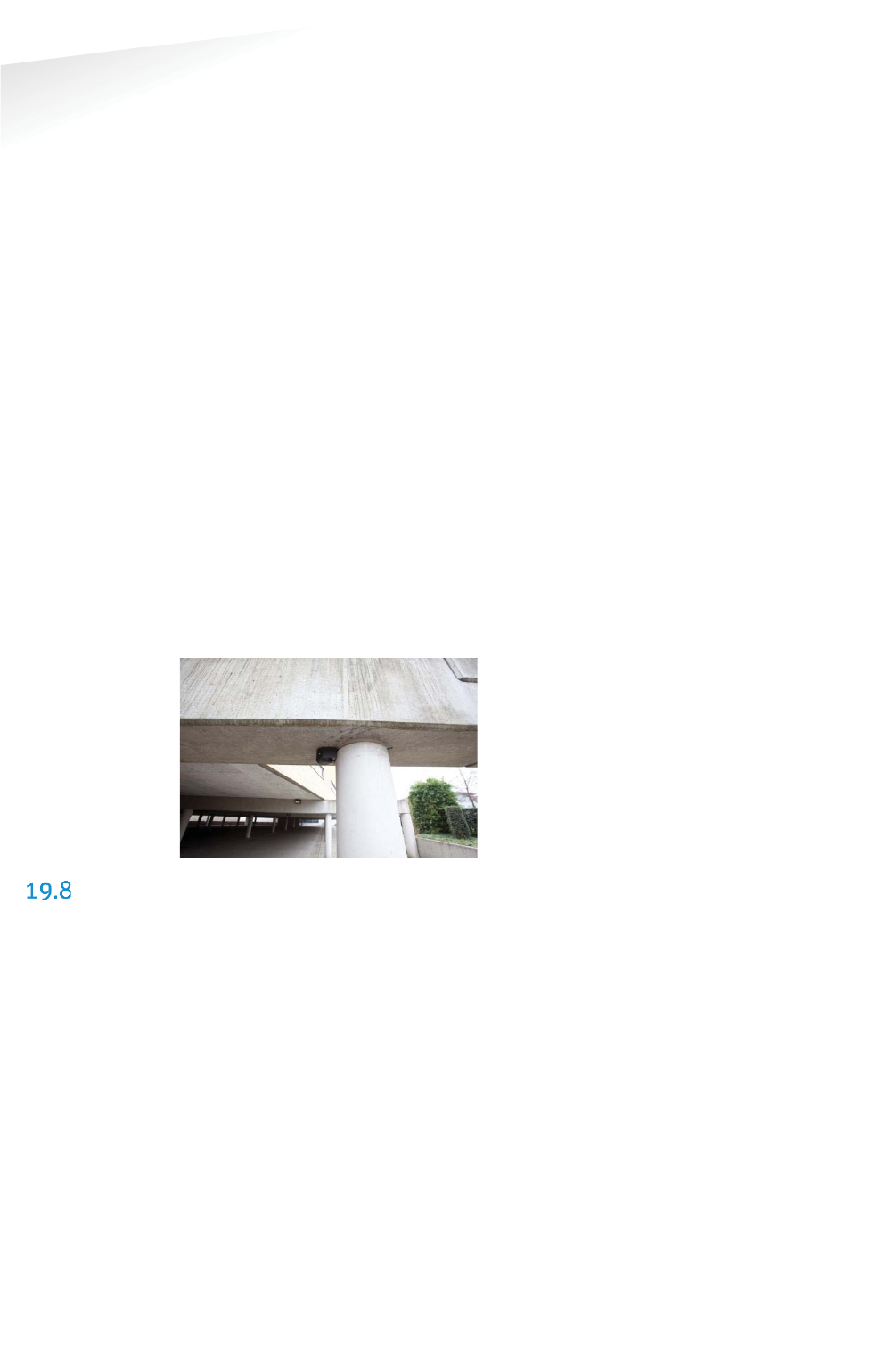
SENSIT SYSTEM | MANUAL
Frequently Asked Questions
99/
111
Frequentl
y
Asked Question
s
W
What is the communication distance between Relay Nodes and other components of
the system?
Below the maximum recommended distances between the different nodes.
SENSIT Gateway Ù Relay Node 25 m (82 ft)
Relay Node Ù Relay Node 50 m (164 ft)
SENSIT Ù Relay Node 25 m (82 ft)
SENSIT Gateway Ù SENSIT 25 m (82 ft)
SENSIT Gateway Ù Relay Node 2G omni-directional 35 m (115 ft)
SENSIT Gateway Ù Relay Node 2G directional 50 m (164 ft)
Data Collector GPRSÙ Relay Node 2G 10 m (33 ft)
Relay Node 2G Ù Relay Node 2G 100m (328 ft)
SENSIT Ù Relay Node 2G omni-directional 35 m (115 ft)
SENSIT Ù Relay Node 2G directional 50 m (164 ft)
How do I replace a Relay Node?
After end of battery life, the SENSIT can easily be taken out of the Relay Node
mounting set. Only the SENSIT sensor configured as Relay Node would need to be
replaced. The batteries of a Relay Node 2G can be replaced, see chapter 10.7.
Can the Relay Nodes also be used for indoor car parks?
Yes, the Relay Nodes can also be used for indoor car parks, see also picture below.
Indoor car parks might require more Relay Nodes due to mounting height
restrictions and influence of concrete on communication.
SENSIT GATEWAY
What is the SENSIT Gateway?
The SENSIT Gateway is the central unit which collects the events from SENSIT
sensors via the Relay nodes and transmits this information to the host system or
SENSIT Interface Software.
What is a Data Collector?
The Data Collector is the previous name for the SENSIT Gateway.
Can I implement data from the SENSIT Gateway directly?
No, this feature is not supported and subject to change. For easy integration we
advise to use the SENSIT Interface Software.
What is the most critical part of the SENSIT system?
The most critical part is the SENSIT Gateway when the power of the SENSIT Gateway
is interrupted or if the SENSIT Gateway is damaged the whole Wireless SENSIT
Network will stop working. Only with a good and powered SENSIT Gateway the
wireless network will start. By using an UPS, (short) power failure can be solved.
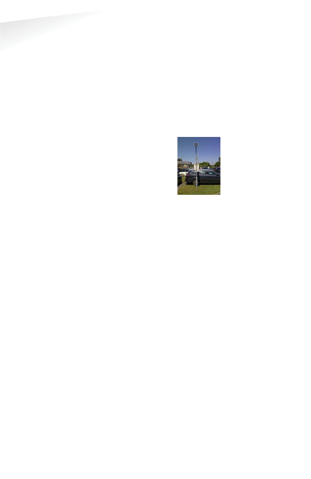
SENSIT SYSTEM | MANUAL
Frequently Asked Questions
100/
111
Frequentl
y
Asked Questi
o
ns
W
Where do I mount the SENSIT Gateway?
The SENSIT Gateway can be installed within 25 m [84 ft] from the first SENSIT node
or Relay Node. Be sure not to position the SENSIT Gateway in a metal enclosure as it
will block the RF communication. The SENSIT Gateway can be mounted in a plastic
housing, which is transparent for RF signals.
What power wiring (cable specs) do I need for the standard Data Collector?
Power: 100-240 VAC, 50-60 Hz, 180mA,
Power input: 5 VDC, max 1A
Power consumption: 5VA
Communication between Data Collector and SIS: Ethernet Cat 5 E
Can the Data Collector GPRS be powered by a solar panel?
There are already several customers who autonomously power
the Data Collector GPRS with a solar panel. Also the Data
Collector GPRS at the Nedap test-site is powered by a solar panel
(since December 2011).
The autonomous solar panel system at the Nedap test-site is a
30Wp Solar panel, a charge regulator and two 22Ah /12V battery
in parallel. See picture at the right
The Data Collector will not consume more than 60mA at 12VDC on average.
Can the SENSIT Gateway be powered by a solar panel?
The SENSIT Gateway can also be powered by a Solar panel and it will not consume
more than 120mA at 12VDC on average.
How much data will a the SENSIT Gateway use?
Normally the data usage will be below 250MB per month.
Can I replace the antenna for one that I can mount on top of a metal box and keep
the SENSIT Gateway inside this metal cabinet?
As for operational purposes this should not be an issue, on the condition that a
suitable antenna is applied. However ETSI and FCC does not allow change of the
antenna, and therefore as a manufacturer we cannot approve antenna change for
this reason.
How often does the SENSIT sensor send an event to the SENSIT Gateway to alert a
status change?
The SENSIT sensor sends an event message immediately after a status change.
The baud-rate of the Data Collector is 115200 can I change it into another value?
The baud-rate of the Data Collector is fixed, you cannot change it.
Can I built the SENSIT Gateway into a pay & display machine?
Yes, when the pay & display machine is featured with Ethernet communication, this
communication could be applied. Keep into consideration that the RF antenna of the
Gateway should be positioned behind RF transparent material (such as plastic) and
not incorporated in metal.

SENSIT SYSTEM | MANUAL
Frequently Asked Questions
101/
111
Frequentl
y
Asked Question
s
SENSIT INTERFACE SOFTWARE (SIS)
W
What is the SIS?
The SIS (SENSIT Interface Software) allows for easy configuration and filtering of
event messages received by the SENSIT Gateway. The SIS enables configuration,
installation, basic administration and integration of the SENSIT system SIS
functionality includes;
x Easy integration via SOAP or REST
x Easy remote support via web interface
x DNNP (Dynamic Node Numbering Protocol)
x Connection of multiple SENSIT Gateways
x Filtering of events
x Easy event configuration
x Easy management of the entire Wireless SENSIT Network
x Automatic calibration
x Debug and analyze tool
x Automatic collection of missing messages
x Configuration of parking bays
x Stand-alone system with control of display per zone.
x Graphics to indicate parking spaces and overstay
Why use a SIS?
Configuration and integration of the data from the SENSIT system becomes much
easier. The site can be accessed remotely allowing Nedap to give you better support
on the installation.
Can I control a display with the SIS?
Yes using a wireless display node built-into a display, the display can become part of
the Wireless SENSIT Network (WSN). You can set in the SIS software which parking
zone the display should control and indicate. See chapter 17.8.7 for more
information. Using this option a simple standalone application could be created with
displays indicating available spaces. No more than 2 wireless displays are allowed in
the WSN to make sure the display messages aren’t influencing the WSN too much.

SENSIT SYSTEM | MANUAL
Frequently Asked Questions
102/
111
Frequentl
y
Asked Question
s
H
How does the overstay sequence work?
The accuracy of detection is of critical importance when using the information for
enforcement applications. You want to avoid issuing unjustified tickets. In the table
below the whole overstay sequence and how to check an overstay is explained.
Event
T
SENSIT
SIS
Car parked
t1
Detected optical +
magnetic
Overdrive
filter (8s)
passed.
t2
Event created and
transmitted,
including;
sequence number,
t2
Event at DC
t3
t4
Event stored in
database, including; t2,
t3 and t4. SIS verifies
sequence number
No change
after 1 hour
t5
Event (created at
t2) retransmitted
t6
Event already stored,
so ignored by SIS
Overstay time
elapsed
t7
Bay status changed
into: overstay, verify
request transmitted
Verify
message
received
t8
Last event (created
at t2) is
retransmitted
Verify event
received
t9
Bay status changed
into: verified overstay
Enforcement officer is notified and arrives at the bay, enforcer sends
verification rrequest
SOAP request
received
t10
Verify request
transmitted
Verify
message
received
t11
Last event (created
at t2) is
retransmitted
Verify event
received
t12
Bay status answered
via the SOAP
Enforcer receives verification and can decide to issue a tticket after his final
observations.
How do we know when a SENSIT or Relay Node is working well?
With the node cross check menu on the SIS you can detect if all SENSIT sensors are
still communicating. Logged in as an advanced user it is possible to get a graphical
overview of the performance of the wireless SENSIT network. For more information,
see chapter E
Error! Reference source not found.
.

SENSIT SYSTEM | MANUAL
Frequently Asked Questions
103/
111
Frequentl
y
Asked Question
s
NETWORK & COMMUNICATION
H
How much events can a SENSIT node store?
Every SENSIT node is capable of storing 32 events in its internal memory.
What causes the latency of a SENSIT sensor?
The latency is built up out of different aspects;
x
The measurement interval;
The interval the SENSIT sensor verifies it status changed, default set at 1
second.
x
The overdrive filter;
The overdrive delay set in the SENSIT sensor is by default set at 8 seconds.
x
The number of hops;
The number of hops a message needs to arrive at the SENSIT Gateway,
every hop takes about 2 seconds.
x
Passive collisions;
In a busy car park multiple SENSIT sensors want to transmit their status
change message simultaneous, which might create passive collisions. In
order to reduce this we advise to ensure that each SENSIT sensor can at
least communicate with 2 Relay Nodes offering multiple communication
paths.
Example with default settings and without passive collisions:
The magnetic and optical sensor measures every second if the status of the
bay is changed. The overdrive filter waits 8 seconds before it transmits the
event. In this example the event is transmitted via 2 Relay Nodes; first from
the SENSIT to the nearest Relay Node and then from this Relay Node to the
Relay Node close to the SENSIT Gateway and finally from this Relay Node to
the SENSIT Gateway. The total (worst-case) time needed is:
Measurement + overdrive + SENSITÆRN + RNÆRN + RNÆ SENSIT Gateway
= 1+8+2+2+2 = 15s
Example with default settings and with one passive collision:
The magnetic and optical sensor measures every second if the status of the
bay is changed. The overdrive filter waits 8 seconds before it transmits the
event. In this example the event is transmitted via 2 Relay Nodes; the
sequence of transmitting the messages is the same as in the example above
but now a collision occurred in the first transmission; another SENSIT
transmitted an event at the same time to the Relay Nodes. The total (worst-
case) time needed is now:
Measurement + overdrive + collision + SENSITÆRN + RNÆRN + RNÆ
SENSIT Gateway = 1+8+10+2+2+2 = 25s
How many seconds does an event message take in general?
The transfer time is depending on the number of hops and if passive collisions take
place. A collision free transfer via one Relay Node takes less than 5 seconds, for
every extra hop add 2 seconds. For a busy parking lot take into account at least 10
seconds extra for possible passive collisions.
Is the package number always increasing per SENSIT?
Yes, the package number is automatically increased in sequence number per SENSIT
and the message is unique based on a combination of SENSIT ID number and
package number.
SENSIT SYSTEM | MANUAL
Frequently Asked Questions
104/
111
Frequentl
y
Asked Question
s
H
How do we map the double words corresponding to "Sent time" and "event time" to
real dates?
The double word is the time in seconds from January 1st 1970 this is also used
within UNIX and therefore also known as 'Unix-time'.
TECHNICAL MATTERS
What is the MTBF of the various components of the Wireless Space Count system?
In the table below the MTBF, MTTR and MTTF is given, so far this are estimated
values.
SENSIT component
MTBF
MTTR
without
spare
MTTR
with
spare
MTTF
SENSIT IR Flush Mount
63 years
7 days
1 hour
~40 years
SENSIT IR
63 years
7 days
1 hour
~40 years
SENSIT Flush Mount
63 years
7 days
1 hour
~40 years
SENSIT Surface Mount
76 years
7 days
1 hour
~40 years
Relay Node
65 years
7 days
1 hour
~40 years
Relay Node 2G
52 years
7 days
1 hour
~40 years
SENSIT Gateway
16 years
14 days
1 hour
~40 years
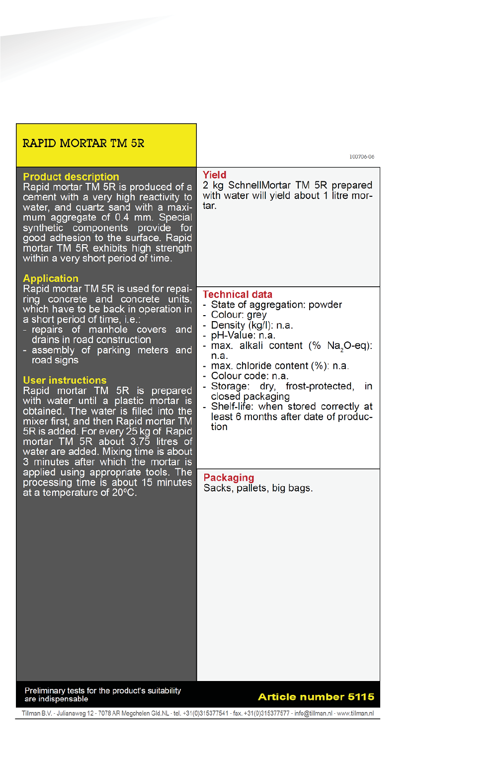
SENSIT SYSTEM | MANUAL
Appendix
105/
111
A
pp
en
d
i
x
20 APPENDIX
A RAPID MORTAR

SENSIT SYSTEM | MANUAL
Appendix
106/
111
A
pp
endi
x
B MODIFIED SILICON POLYMER
S
Sabatack Fast
u l t r a - f a s t b o n d i n g
B.1 Description
Sabatack Fast is an ultra fast-acting 2-component, elastic, humidity-curing, MS
polymer-based construction adhesive. Its primary use is bonding with fast
hardening, handling after only 2 hours, which makes this product excellent for use in
mass production. Sabatack Fast has a medium viscosity and a high modulus
elasticity.
B.2 Field of application
Industrial and hand-made vehicle and coachwork construction, marine, ventilation
and air conditions, electro-technology, equipment assembly, metal and tin
processing, plastics technology, civil & environmental engineering and building &
construction. For the elastic bonding of frames, profiles, plates etc. Also for sealing
seams, overlaps, joints and cracks. Suitable for interior and exterior use. Excellent for
use in mass production.
B.3 Advantages
x fast and controlled curing, high end strength
x adhesion without primer, fast drying
x can be painted wet-on-wet, hardly any shrinkage
x no blistering, almost odorless
x free from solvents, isocyanates and silicones
x UV-stable, high temperature resistance
x certificates: Wheelmark (164.106/1121/WCL MED0326), ISEGA (in
connection with HACCP)
B.4 Method of use
For instructions for use, repaint ability and pre-treatment, see the relevant info
sheets at w
www.saba.nl

SENSIT SYSTEM | MANUAL
Appendix
107/
111
A
pp
endi
x
B.5 TECHNICAL DATA
Order information
Other packaging and colours on request. The shelf life may vary for large packaging.
Safety recommendations
For more information about safety, see the relevant SABA safety data sheet.
Component A Component B
Basis MS polymer, humidity-curing MS polymer,
humidity-curing
Density (EN 542) approx. 1.380 kg/m3 approx. 1.144
kg/m3
Solids content
approx. 100% approx. 85%
Open time
(23 °C, 50% RLV) approx. 10 minutes
Tack free
(23 °C, 50% RLV) completely after approx. 12
hours
Cure rate
(23 °C, 50% RLV) even after 48 hours
Hardness Shore A
(EN ISO 868) approx. 55
Volume alteration (EN ISO 10563) < 5%
Modulus at 100%
(ISO 37/DIN 53504) approx. 1.5 N/mm2
Tensile strength
(ISO 37/DIN 53504) approx. 2.6 N/mm2
Elongation at break
(ISO 37/DIN 53504) approx. 330%
Shear strength
(ISO 4587) approx. 1.7 N/mm2
Working temperature
min. +5 °C to max. +35 °C
Storage temperature
min. +5 °C to max. +25 °C
Temperature resistance
min. -40 °C to max. +120 °C
Short temperature resistance
max. +180 °C (30 minutes)
Packaging
dual-cartridge
Contents
490 ml (contains 7 items)
Color
White (RAL 9003) black (RAL 9011)
Article No.
100201 DJW 100862 DJW
Shelf life
9 months (in unopened packaging)

SENSIT SYSTEM | MANUAL
Appendix
108/
111
A
pp
endi
x
C POLYURETHAN
P
P E R M A P U R® 2 6 5 4 A / B
Universal Polyurethane liquid adhesive
PERMAPUR® 2654 A/B consists of two components A-component (Polyol) and a B-
component (Isocyanate). The resin is supplied in a bi-pack. PERMAPUR 2654 A/B is
used as an universal polyurethane resin which can be applied by pouring the fluid.
The system is insensitive to moist and shows no blistering and is therefore less
critical in processing.
Technical details
Color: A-component black fluid
B component dark brown fluid
Color mix: Black
Processing time: 10 min / 20°C
Gel time: 15 min / 20°C
Curing time: 24 h /20°C
Viscosity: 4.500 mPa.sec/20°C
Hardness: 45° Shore D
Specific gravity: 1,5 g/cm3
Specific resistance: 1 x 10¹⁴ W.cm
Breakdown voltage: 20 KV/mm
Max. Temperature: -25°C tot +120°C
Water absorption: <1%
Storage: At room temperature (20 ° C) in tightly closed Verpa
Branching 12 months

SENSIT SYSTEM | MANUAL
Appendix
109/
111
A
pp
endi
x
D FCC AND IC DECLARATIONS
Compliance statements (part15.19)
This device complies with part 15 of the FCC Rules and with Industry Canada’s
licence-exempt RSSs. Operation is subject to the following two conditions:
(1) This device may not cause interference; and
(2) This device must accept any interference, including interference that may cause
undesired operation of the device.
Warning (15.21)
Changes or modifications not expressly approved by the party responsible for
compliance could void the user’s authority to operate the equipment.
Cet appareil se conforme aux normes RSS exemptés de license du Industry Canada.
L’opération est soumis aux deux conditions suivantes:
(1) cet appareil ne doit causer aucune interférence, et
(2) cet appareil doit accepter n’importe quelle interférence, y inclus interférence qui
peut causer une opération non pas voulu de cet appareil.
Les changements ou modifications n’ayant pas été expressément approuvés par la
partie responsable de la conformité peuvent faire perdre à l’utilisateur l’autorisation
de faire fonctionner le matériel.
FCC and ISED Radiation Exposure Statement
This equipment complies with FCC (OET Bulletin 65) and Canadian radiation
exposure limits set forth in RSS-102 for a uncontrolled environment. This equipment
should be installed and operated with a minimum distance of 20 cm between the
radiator and your body. This transmitter must not be co-located or operating in
conjunction with any other antenna or transmitter.
Cet équipement est conforme a RSS-102 limites énoncées pour un environnement
non contrôlé. Cet équipement doit être installé et utilisé avec une distance minimale
de 20 cm entre le radiateur et votre corps.
ISED EMC Declaration
This Class B digital apparatus complies with Canadian ICES-003.
Cet appareil numérique de Classe B est conforme à la norme Canadienne ICES-003.
FCC Information to the user (15.105(b))
Note: This equipment has been tested and found to comply with the limits for a class
B digital devices, pursuant to part 15 of the FCC Rules. These limits are designed to
provide reasonable protection against harmful interference in a residential
installation. This equipment generates, uses and can radiate radio frequent energy
and, if not installed and used in accordance with the instructions, may cause harmful
interference to radio communications.
However, there is no guarantee that interference will not occur in a particular
installation. If this equipment does not cause harmful interference to radio or
television reception, which can be determine by turning the equipment off and on,
the user is encouraged to try to correct the interference by one or more of the
following measures:
• Reorient or relocate the receiving antenna.
• Increase the separation between the equipment and receiver.
• Connect the equipment into an outlet on a circuit different from that to which the
receiver.
• Any changes or modifications not expressly approved by the party responsible for
compliance could void the user's authority to operate the equipment.
• To ensure compliance with FCC regulations, use only the shielded interface cables
provided with the product, or additional specified components or accessories that
can be used with the installation of the product

SENSIT SYSTEM | MANUAL
Appendix
110/
111
A
pp
en
d
i
x
F DISCLAIMER
This information is furnished for guidance, and with no guarantee as to its accuracy
or completeness; its publication conveys no license under any patent or other right,
nor does the publisher assume liability for any consequence of its use; specifica-
tions and availability of goods mentioned in it are subject to change without notice;
it is not to be reproduced in any way, in whole or in part, without the written consent
of the publisher.

SENSIT SYSTEM | MANUAL
Appendix
111/
111
A
pp
endi
x
G DOCUMENT REVISION
VVersion
DDate
CComment
1.3.3
24-02-2014
Start documents and new corporate style
1.4
14-04-2014
Adjustments for 1.4 release.
1.4.1 12-05-
2014
Adjustments for
release 1.4.1, RelayNodeTool added,
Document renamed.
1.4.2
15-07-
2014
Adjustments for release 1.4.2, FCC & IC Declaration
and some small textual improvements.
1.4.3 27-10-
2014
Adjustments for release 1.4.3, some small textual
improvements.
1.5.0 17-12-
2014
Adjustments for release 1.5.0; Parking enforcement
screens.
1.5.1
17-12-2014
Adjustments for release 1.5.1; DNNP
1.5.2
10-03-2015
Adjustments for release 1.5.2; EPL
1.5.3 28-04-
2015
Adjustments for release 1.5.3, some small textual
improvements.
1.5.5 12-11-
2015
Adjustments for release 1.5.5; EPL improvements,
support widget
1.5.6
04-04-2016
Adjustments for release 1.5.6; SG version added.
1.6 06-06-201
7
Adjustments for release 1.6; SENSIT Gateway
, Back up
battery, Configuration Tool and SIS Maps.