NBB Controls Components BCD915 Industrial Remote Control Transmitter User Manual manual
NBB Controls + Components AG Industrial Remote Control Transmitter manual
manual
®
Receiver Type /Version
Factory No.
Frequency
Transmitter Type /Version
Factory No.
Frequency
%
%
%
Portable transmitter.
Receiver with integrated mounting holes.
Multi-pin connecting cable for the receiver according to your specifications.
For explanatory notes on obtaining an operating permit please refer to registration docu-
ments enclosed in the appendix of this operating instruction. Observe all applicable work-
safety and accident prevention regulations carefully. Only fully trained, authorized per-
sonnel may use the NBB radio control equipment. Components, etc. built into the NBB
equipment for safety purposes must be regularly inspected.
Failure to observe these recommendations will put both you yourself and others at risk.
Under these circumstances, NBB rescinds the guarantee and any other form of liability.
This radio control unit is designed exclusively for the control of construction machines
and industrial plants. Only under these conditions are the safety systems (STOP and zero
setting) fully effective. No other form of use is permitted. Any non-observance of this con-
dition will relieve NBB of all liability.
The actual delivery specification is as detailed on the confirmation of order or the delivery
note accompanying the goods!
Even if you are accustomed to working with radio control systems, read these operating
instructions carefully before using this equipment. Only this document contains the latest
information relating to your NBB radio control system.
If the NBB radio control unit develops a fault, it must be shut down immediately. The trans-
mitter should be switched off with the STOP key. The connecting cable must be discon-
nected at the receiver from the connecting socket (terminal) of the unit to be controlled .
The repair of the equipment must not be carried out other than by NBB or an NBB authori-
zed technician.
Page 1
3. TRANSMITTER
1. STANDARD SPECIFICATION
2. SAFETY PRECAUTIONS
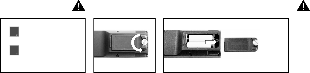
Switching on: To make the unit ready for use, unscrew the screw plug of the battery com-
partment on the back of the transmitter and remove the cover. Insert 2 charged AA Mi-
gnon batteries 1,2V NiMH (or batteries 1,5V - not rechargeable) into the battery compart-
ment, close the cover and tightenthe screw plug again.
Rechargeable batteries (NiMH or NiCd) must be fully charged before first use
Never attempt to charge standard non rechargeable AA batteries
!
1,5V !
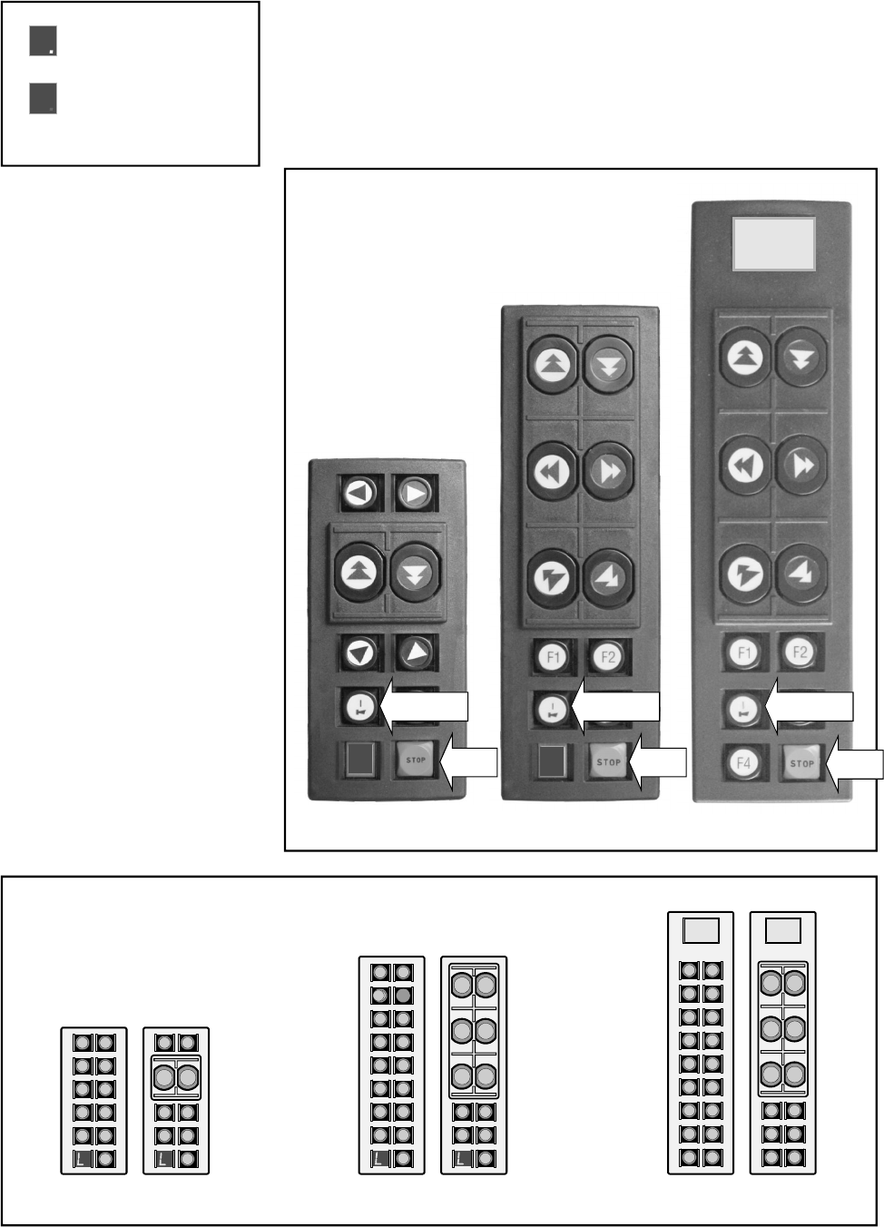
The functions of the receiver are released with the “ON/HORN” key.
The receiver has to be switched off with the "STOP" key when work is finished.
AreddotflashesonthePlanardisplayduringoperation.
The transmitter switches off automatically, if the keys are not pres-
sed within a specified time. The red dot goes out.
Optional: Transmitter for continuous operation possible.
Energy saving function:
*The duration of this stand-by can be specified when ordering.
Operation:
The red dot flashes.
8
Slowly flashing:
Batteries are to low, to
operate the transmitter.
L
Page 2
When the letter "L" flashes quickly on the Planar display, the batteries (rechargeable or not
rechargeable) are nearly empty.
The transmitter can be operated for approximately 30 minutes more in this condition.
During this time, bring the unit to a safe position, switch off the transmitter and install 2
charged AA Mignon batteries 1,2V NiMH (or batteries 1,5V - not rechargeable).
STOP STOP STOP
Planar-D2 Planar-C2 Planar-B2
Examples:
L. L.
Display
Available Planar-B, -C, -D upper housings:
B1 B2
C1 C2
. .
D1 D2
. .
Operation:
The red dot flashes.
8
Quickly flashing:
Batteries are nearly empty.
Transmitter can be operated
for appr. 30 minutes more.
L
ON/HORN ON/HORN ON/HORN
4. Base Unit
for Planar-B, Planar-C
and Planar-D
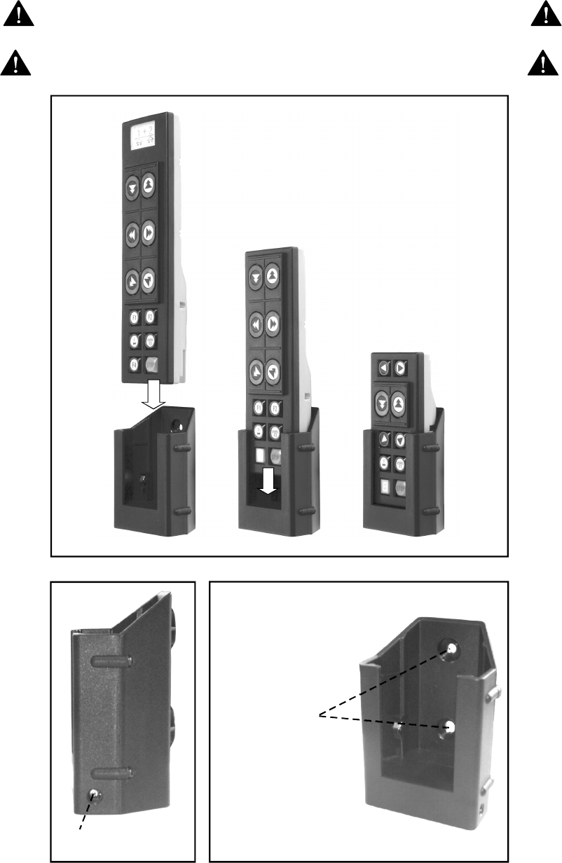
When a transmitter is operated with AA Mignon 1,2 V NiMH rechargeable batteries, these
batteries automatically charge inside the transmitter in the optional base unit. To start the
charging process simply slide the transmitter into base unit (see image 1). An automati-
cally controlled charging process keeps batteries from over-charging. Base unit has to be
connected to a power supply(optional also with dc-charger) – (see image 2).
WARNING: Never try to charge regular AA batteries (non-rechargeable
batteries) – danger of explosion!
WARNING: Charge 8 hours (2000 mA/h) after total discharge of batteries or
before first use.
Page 3
Pre-drilled
mounting holes
Connection power plug/
car power plug
Image 1
Image 2
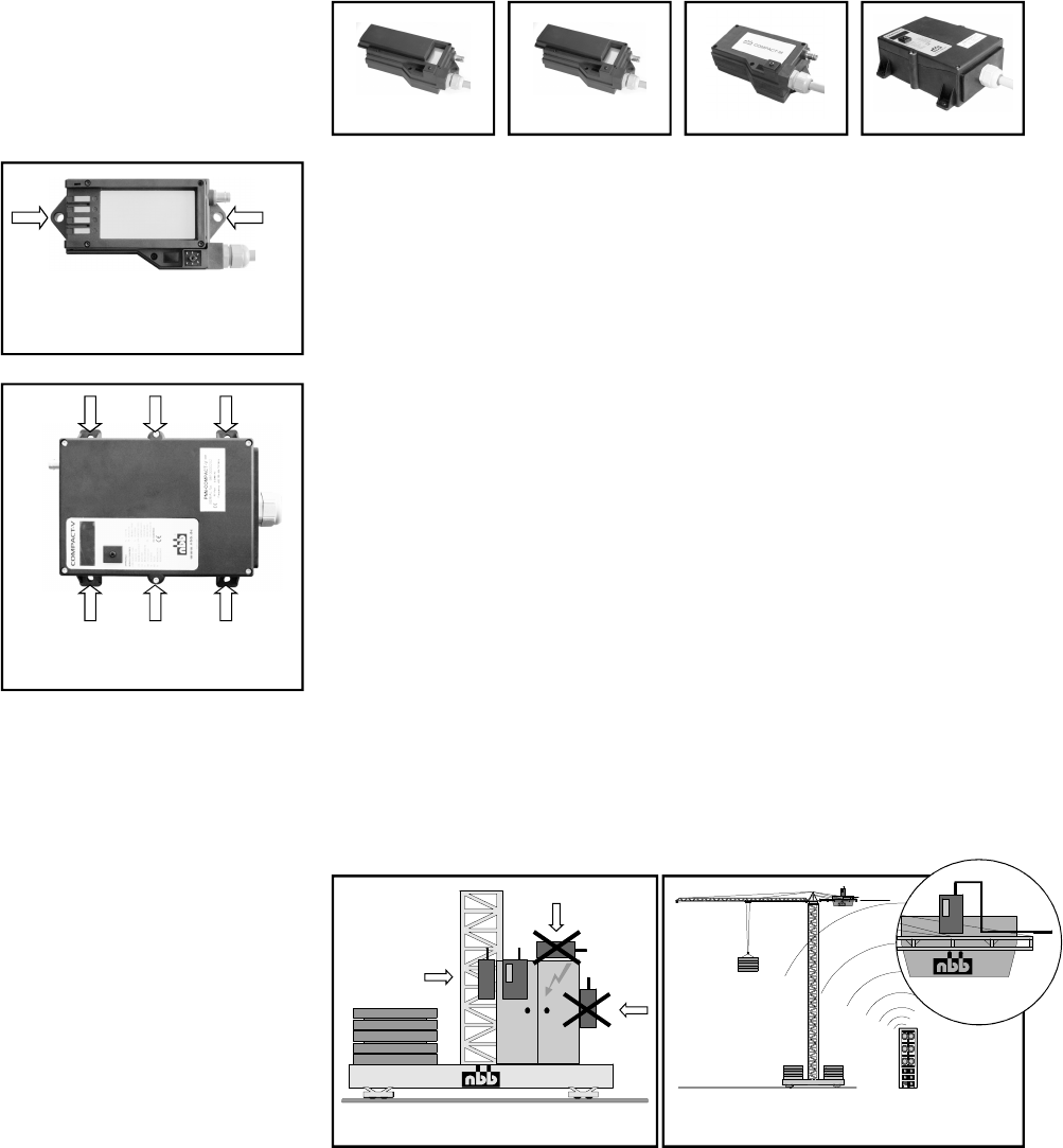
4. RECEIVER
R-16, R-CAN
Compact-M, Compact-V
Page 4
Mounting possibility of the receiver
R-16, R-CAN or the Compact-M.
Mounting possibility of the receiver
Compact-V.
.
WRONG
Mounting on a tower slewing crane.
Top slewing crane: Mount the antenna with
extension cable horizontally.
RIGHT
The receiver is connected to the unit to be controlled with the multi-pin connecting
cable supplied. Please observe the instructions issued by the manufacturer of the unit
to be controlled!
The power supply of the receiver is generally effected by the connecting cable.
We recommend urgently to realize this connection via a central, well
accessible, multi-pin plug connector (for example HTS-plug connector series
HE/HB/HN/HA or comparable ones of other manufacturers) to make possible a quick
and clear fault diagnosis in the service case and to take off the receiver without an
expenditure of assembly.
In general, an earth lead is required in case the units to be controlled have not pre-
viously been operated by radio control. Failing this, the
receiver electronic circuit will not receive any power supply. Ensure that the opera-
ting voltage of the receivercomplieswiththeelectricalspecificationsof
the unit to be controlled. The applicable operating voltage is specified in the supp-
lement.
Never expose the receiver to a high pressure cleaning jet. This applies to the
transmitter also.
The receiver should always be fixed vertically at the outside panel of the swit-
ching cabinet. (The antenna should always reach over the top of the panel.)
You have to make sure that the antenna is not shielded by metal parts totally or part-
ly.
Mounting the receiver in a cabine or in a switching cabinet the antenna should be
layed with an extension cable to the outside and be attached with the fastening
strapping as horizontally as possible with distance to the shielding metal parts.
In general the antenna should always be mounted in such a way so that the antenna
is still visible with each change of position of the transmitter.
%
%
%
%
%
%
WRONG
RIGHT
Compact-MR-16 R-CAN Compact-V
Safety equipment in the NBB-radio remote control:
In the transmitter
In the receiver:
If the NBB radio remote control is not used for a long period, it is urgently recommended -
if you use rechargeable batteries - that they should be charged now and again (about
every 4 weeks). This prevents deep discharges of the batteries and prolongs their useful
life. If you shut down the NBB radio remote control for a long period, we recommend you
take the batteries out of the transmitter.
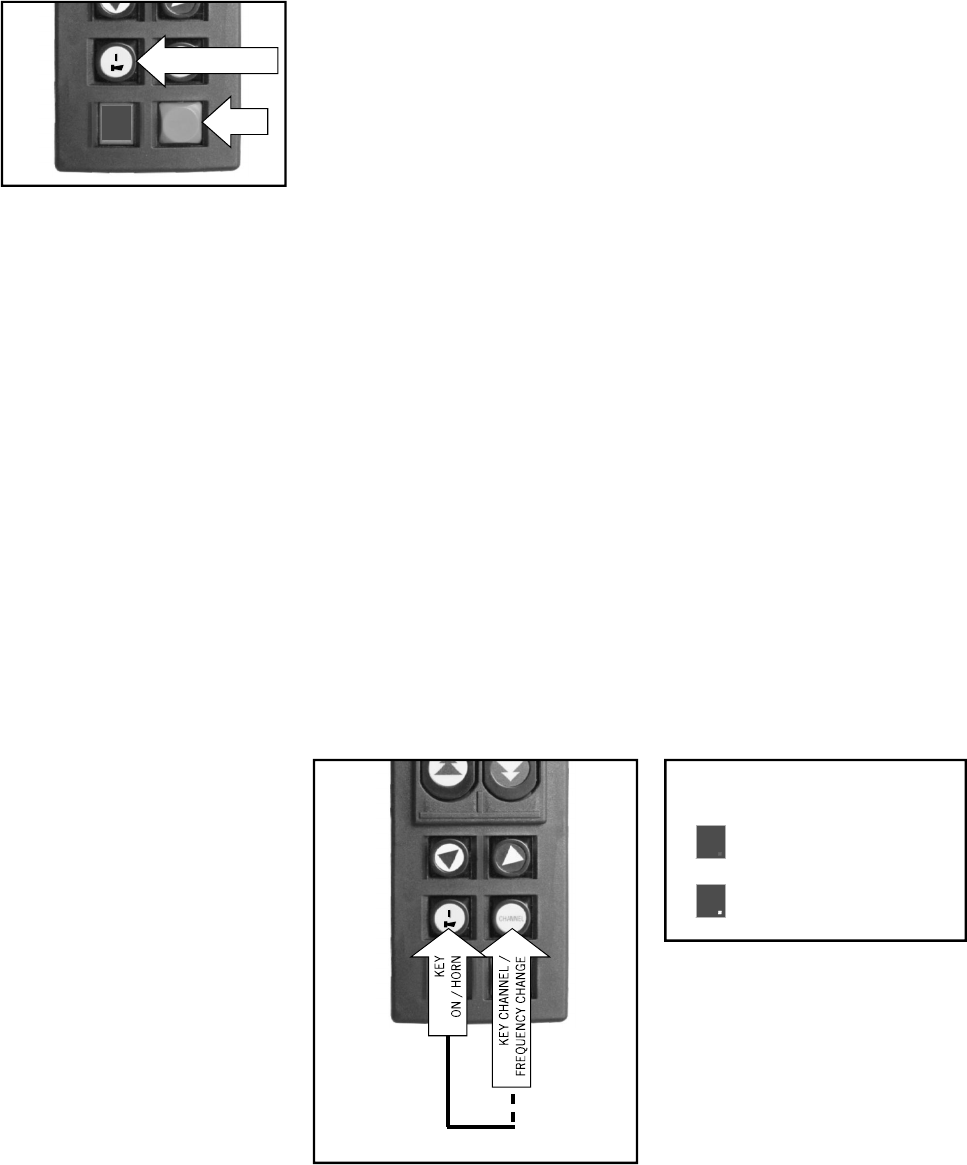
Frequency change Planar-B, -C, -D:
Channel number:
,thiscomprisesmainly:
STOP (transmitter ON/OFF) with automatic disconnection of the power supply.
Automatic zero positioning.
Automatic zero setting when switching back on after radio interruption.
Locking of the radio commands at relay level in the event of a defective STOP circuit.
To ensure fault-free operation, please follow precisely the following rules for operation:
The unit to be controlled can only be switched on - it is assumed that the transmitter is
ready to operate - when no command unit is actuated. The command necessary to do so
is triggered by the key "ON/HORN". This triggers a horn signal in the unit to be controlled.
After switch-on of the facility to be controlled, this key is used for repeated emission of the
horn signal in accordance with working regulations.
To change the frequency, keep the "ON/HORN" key pressed down. T h e n o p e r a t e t h e
"CHANNEL / FREQUENCY CHANGE" key. If the receiver locks into the new frequency, a
horn signal is given (if present) and the unit to be controlled is ready for operation. Please
observe the particular postal approval regulations of the concerned country.
When changing the frequency the channel number lights up shortly in
the display: First the decimal place, then the digit.
During operation the choosen channel can be shown by pressing the “CHANNEL / FRE-
QUENCY CHANGE” key.
%
%
%
%
Page 5
CHANNEL
STOP
STOP
L.
CHANNEL
First the decimal place
is shown.
5
Then the digit is shown.
3
Channel number: f.e. Channel 53
FREQUENCY CHANGE
RADIO ON /HORN
5. OPERATING THE UNIT
Page 6
6. FUNCTION CHECK To maintain operational safety, a regular function check of the NBB radio remote control is
necessary. In single-shift day-to-day operation, we recommend performing this check at
least once a week. Checking is possible using the display lights provided on the receiver.
To do so, the transmitter must be set to the ready-to-operate state.
First connect just the receiver - the transmitter remains switched off.
Activate the transmitter by pressing the key "START/ON/HORN" at the Planar
transmitter.
Now check the commands (always start with the lowest stage) and check for
correct reaction oftheunittobecontrolled.
Ensure in particular that there is nobody in the danger area.
.PresstheSTOPkeyatthetransmitter.Thenobserveiftheunittobe
controlled is switched off (time to switch off according to the application).
(Optional with integrated charger)
RADIO PRESENT.
If the LED fails to come on:
1. Check that the transmitter is on.
2. Check the power supply of the receiver.
3. (Optional) Irregular flashing of the LED:
Check or change the current radio channel.
(Without charger)
RADIO PRESENT.
If the LED fails to come on:
1. Check that the transmitter is on.
2. Check the power supply of the receiver.
3. (Optional) Irregular flashing of the LED:
Check or change the current radio channel.
POWER ON. If LED fails to come on, check the power supply.
If the power lead is OK, call in the after-sales service.
HF PRESENT. Steady light when transmitter is switched on
(insignificant for scanner operation).
Flashes evenly during fault-free operation.
Irregular flashing means that the HF channel is probably at
fault - please set another channel.
If this LED flashes, the HF channel is at fault (not for scanner
operation).
Steady light notifies the operator that an output function
is critical due to high current.
%
%
%
%
%
%
%
%
%
ACCIDENT RISK!
STOP check
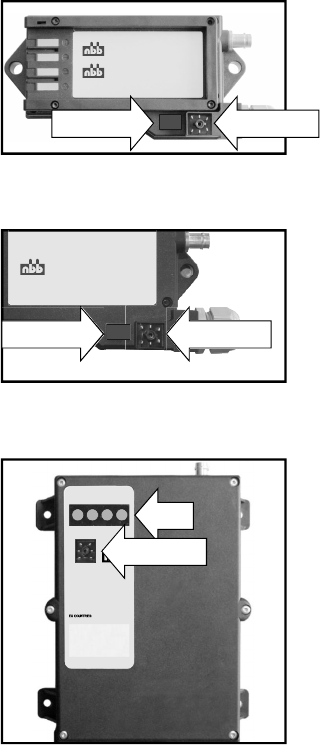
Checking the LED at the receiver R-16 and R-CAN:
The Green LED flashes:
Checking the LED at the receiver Compact-M:
The Green LED flashes:
Checking the LED's at the receiver Compact-V:
LED 1 green:
LED 2 yellow:
LED 3 green:
LED 4 red:
Service plug: For NBB service only.
COMPACT-M
R-16
R-CAN
1 2 3 4
www.n bb.de
®
COMPACT-V
X
3.820.1195
LEDS
SERVICE PLUG
LED RADIO ON SERVICE PLUG
LED RADIO ON SERVICE PLUG

Page 7
The rating plates state the type of transmitter or receiver, the factory number, the fre-
quency range and the approval number for non EU countries.
Always state the factory number in all your queries.
Your NBB radio remote control is largely maintenance-free. Nevertheless, please bear in
mind the following points:
The STOP key must be easy to move.
Remove any leftover building materials!
During electro-welding work on the unit to be controlled, disconnect the receiver from
the current supply! Otherwise there is a risk of damage to the receiver's electronic sy-
stem!
Check wear and tear parts like dust shield tops regular!
We grant a function warranty for 12 months after the sale date for all NBB radio remote
controls (transmitter, receiver, charger). The warranty covers working time and material
used. Shipping costs shall be charged to the customer. The warranty shall not cover:
wear and tear parts, relays and batteries. The function warranty shall be invalidated in the
case of damage, accident damage, negligence, incorrect use, non-compliance with ope-
rating conditions, non-compliance with operating, testing and maintenance instructions,
and repairs or unit modifications not authorised by NBB. NBB shall not be liable for indi-
rect damage and reserves the right to decide on repair or replacement.
Do not attempt to continue working with a defective NBB radio remote control. Even initial-
ly minor defects might be the start of a more extensive defect.
Do not try to repair the NBB radio remote control yourself. If there is any fault please con-
tact your dealer or our company.
%
%
%
%
10. IN CASE OF DEFECTS
9. WARRANTY
8. MAINTENANCE
7. RATING PLATES
Example:
Transmitter Type / Version:
Factory No.:
Frequency:
Planar-B (or C or D)
999 899 4990
915 -916.65 Mhz
Receiver Type / Version:
Factory No.:
Frequency:
Compact-V
999 899 4990
915 -916.65 Mhz

USA:
IC CANADA:
NOTE: This equipment has been tested and found to comply with the limits for a Class A di-
gital device, pursuant to Part 15 of the FCC Rules. These limits are designed to provide
reasonable protection against harmful interference when the equipment is operated in a
commercial environment. This equipment generates, uses, and can radiate radio frequen-
cy energy and, if not installed and used in accordance with the instruction manual, may
cause harmful interference to radio communications. Operation of this equipment in a resi-
dential area is likely to cause harmful interference in which case the user will be required
to correct the interference at his own expense.
The installer of this radio equipment must ensure that the antenna is located or pointed
such that it does not emit RF field in excess of Health Canada limits for the general popula-
tion; consult Safety Code 6, obtainable from Health Canada’s website www.hc-
sc.gc.ca/rpb
ATTENTION:
Changes or modifications not expressly approved by the manu-
facturer could void the user's authority to operate the equipment!
1. FCC1US- andCANADAIC
Page 8

Page 9
®
TECHNICAL DATA
Operating ambient temperature -20 to +70 °C
Insulation class - Protection IP 65
Transmission frequency range see product label
The use of synthesizer technology permits frequencies to be selected in accordance with the appropriate
waveband for the country of use.
Low frequency modulation GFSK
Data repetition rate about 15 ms / 60 ms
Baud rate
Range about 100 m
Power input about
RF ouput (Fieldstrength) <50mV/m
Weight (without battery) Size (L x W x H)
TRANSMITTER Planar-B, Planar-C, Planar-D
1200 - 9600 Baud (Bit / sec.)
60 mA
(3 Meter measuring distance acc. 47 CFR Part 15.249)
Planar-B 210 g 21,5 x 5,6 x 3,7 cm
Planar-C 205 g 18,0 x 5,6 x 3,7 cm
Planar-D 190 g 12,3 x 5,6 x 3,7 cm
Power supply 2 x rechargeable batteries 1,2V AA NiMH
(or 2 x batteries 1,5V - not rechargeable)
Operating duration >30h (2000mA/h NiMH batteries)
Reception frequency range see product label
Data security:
Generates a CRC code with a Hamming distance = 4. Generates a neutral position.
Addressing of each transmitter with its own, unique combination (max. 2 possible combinations).
Security EMERGENCY STOP with selftest.
max. switching voltage 250V AC (12V / 24V DC - R-16, R-CAN, Compact-M, Compact-V)
max. switching current 4A AC (3A DC at 12V / 24V - R-16, R-CAN, Compact-M, Compact-V)
max. switching power 1000 VA
Weight Size (L x W x H)
R-16, R-CAN 640 g 18 x 9,7 x 4,4 cm
(potted) 800 g
Compact-M 640 g 18 x 9 x 7 cm
(potted) 800 g
Compact-V (potted) 1,5 kg 21,5 x 16 x 6,5 cm
RECEIVER R-16, R-CAN, Compact-M, Compact-V
16

®
APPROVALS AND CERTIFICATES
Page 10
USA FCC ID: SJ7BCD915
CANADA IC: 2634B-BCD915
Bedienungsanleitung
englisch, Teile-Nr. 3.150.1340, Stand 21.07.09
Planar-B, -C, -D, USA, Kanada, 915 Mhz,
©NBBControls+ComponentsAG
Otto-Hahn-Straße 3-5
DE-75248 Ölbronn-Dürrn
Tel.: 0 72 37 / 9 99 - 0
Fax: 0 72 37 / 9 99 - 1 99
eMail: sales @nbb.de
http://www.nbb.de
We reserve the right to alter specifications without notice.