NBB Controls Components
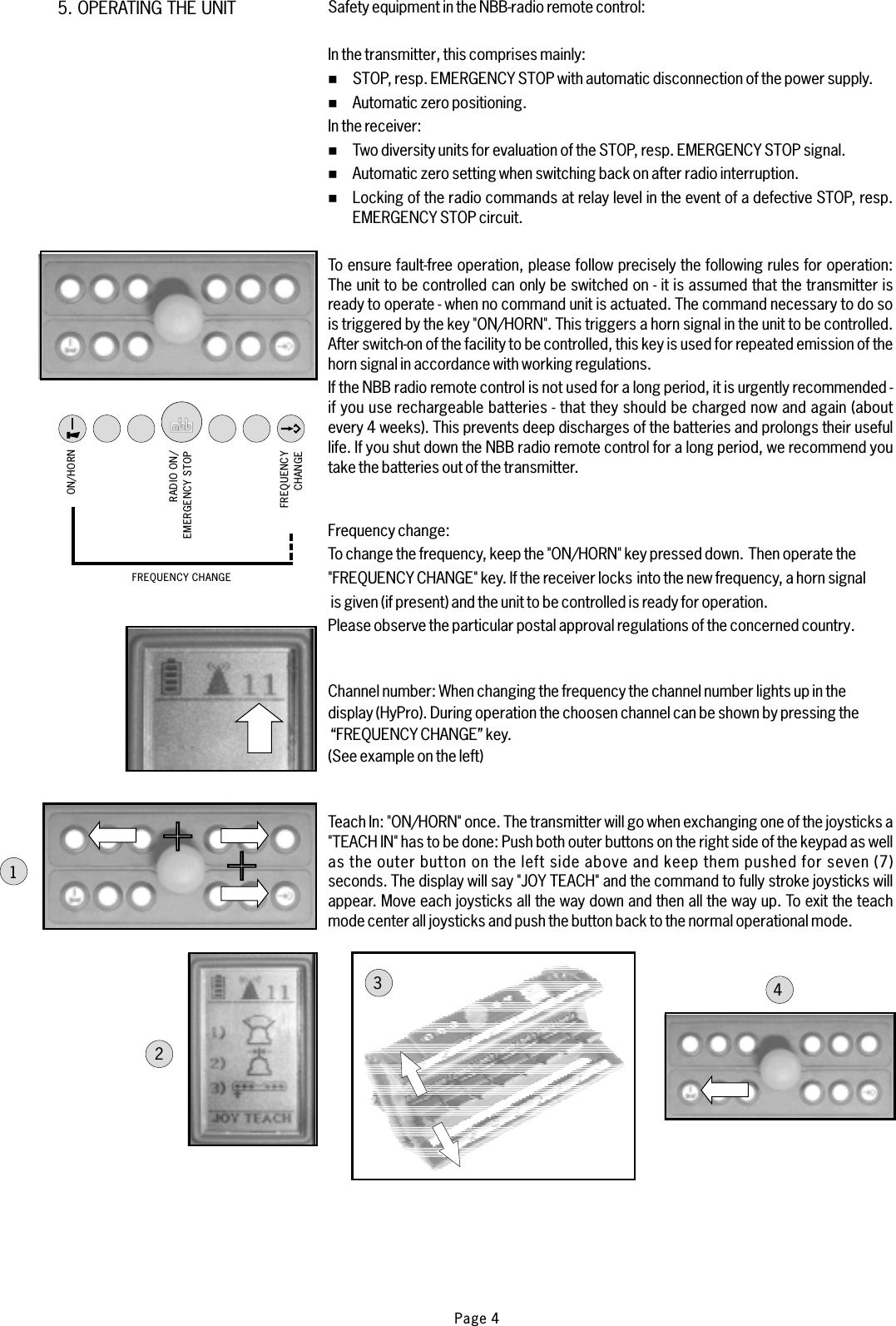
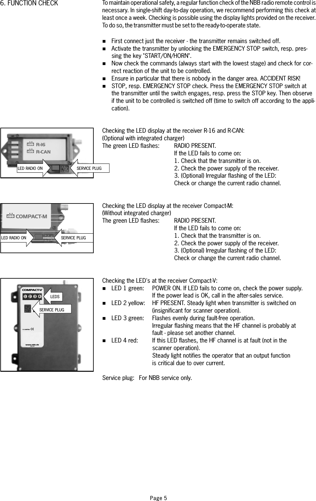
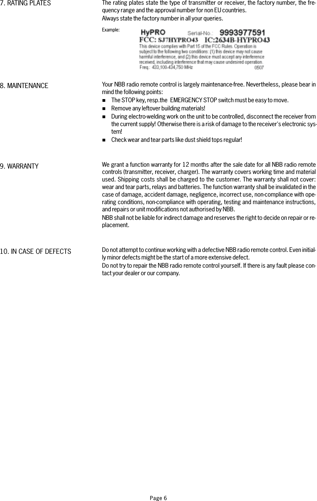
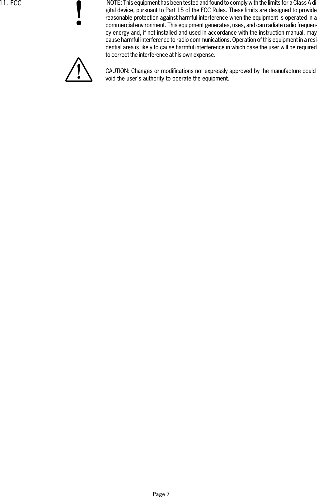
 HYPRO43 HyPro Radio Remote Control User Manual manual

NBB Controls + Components AG HyPro Radio Remote Control manual

manual

®Compact-M, Compact-VCompact-M, Compact-VHyPro-8USAHyPro-8USAR-16, R-CANR-16, R-CANHyPro-6USAHyPro-6USAReceiver TypeFactory No./ VersionFrequencyTransmitter Type / VersionFactory No.FrequencyOPERATING INSTRUCTIONSOPERATING INSTRUCTIONS
%%%Portable transmitter.Receiver with integrated mounting holes.Multi-pin connecting cable for the receiver according to yourspecifications.For explanatory notes on obtaining an operating permit please refer to registration docu-ments enclosed in the appendix of this operating instruction. Observe all applicable work-safety and accident prevention regulations carefully. Only fully trained, authorized per-sonnel may use the NBB radio control equipment. Components, etc. built into the NBBequipment for safety purposes must be regularly inspected.Failure to observe these recommendations will put both you yourself and others at risk.Under these circumstances, NBB rescinds the guarantee and any other form of liability.This radio control unit is designed exclusively for the control of construction machinesand industrial plants. Only under these conditions are the safety systems (STOP, resp.EMERGENCY STOP, zero setting) fully effective. No other form of use is permitted. Anynon-observance of this condition will relieve NBB of all liability.Optional:The actual delivery specification is as detailed on the confirmation of order or the deliverynote accompanying the goods!Even if you are accustomed to working with radio control systems, read these operatinginstructions carefully before using this equipment. Only this document contains the latestinformation relating to your NBB radio control system.If the NBB radio control unit develops a fault, it must be shut down immediately. The trans-mitter should be switched off with the STOP key, resp. EMERGENCY STOP switch. Theconnecting cable must be disconnected at the receiver from the connecting socket (ter-minal) of the unit to be controlled . The repair of the equipment must not be carried out ot-her than by NBB or an NBB authorized technician.1. STANDARD SPECIFICATION2. SAFETY PRECAUTIONS3. TRANSMITTER Switching on: To make the unit ready for use, unscrew the screw plug of the battery com-partment on the back of the transmitter and remove the cover. Insert 2 charged AAMignon batteries 1,2V NiMH (or batteries 1,5V - not rechargeable) into the batteryCompartment, close the cover and tighten the screw plug again.Rechargeable batteries (NiMH or NiCd) must be fully charged before first use!Never attempt to charge standard non rechargeable 1,5V AA batteries!Page 1
..3. TRANSMITTER HyProSTOPSTARTAKKU LEERDISPLAY FUNK ONDISPLAY AKKUThe power supply to the transmitter is activated with the “STOP” key, resp.EMERGENCY STOP switch.(When pressed, the EMERGENCY STOP switch can also be secured by removing thekey cap.)The green LED on the transmitter control panel must flash regularly.Commands can now be put in by means of the controls.When the red "Battery" indicator lamp lights up, the batteries (rechargeable or notrechargeable) are nearly empty.The transmitter can be operated for approximately 30 minutes more in this condition.During this time, bring the unit to a safe position, switch off the transmitter and install2 charged AA Mignon batteries 1,2V NiMH (or batteries 1,5V - not rechargeable).The transmitter switches off automatically, if the keys are not pres-sed within a specified time. The LED goes out.Optional: Transmitter for continuous operation possible.Energy saving function:*The duration of this stand-by can be specified when ordering.Operation:The red dot flashes.Quickly flashing: Bat-teries are nearly empty.Transmitter can beoperated for appr. 30minutes more.Page 2
4. RECEIVERR-16, R-CANCompact-M, Compact-VCompact-MR-16 R-CAN Compact-V.Mounting possibility of the receiverR-16, R-CAN or the Compact-M.Mounting possibility of the receiverCompact-V.The receiver is connected to the unit to be controlled with the multi-pin connectingcable supplied. Please observe the instructions issued by the manufacturer of the unitto be controlled!The power supply of the receiver is generally effected by the connecting cable.We recommend urgently to realize this connection via a central, wellaccessible, multi-pin plug connector (for example HTS-plug connector seriesHE/HB/HN/HA or comparable ones of other manufacturers) to make possible a quickand clear fault diagnosis in the service case and to take off the receiver without anexpenditure of assembly.In general, an earth lead is required in case the units to be controlled have not pre-viously been operated by radio control. Failing this, thereceiver electronic circuit will not receive any power supply. Ensure that the opera-ting voltage of the receiver complies with the electrical specifications ofthe unit to be controlled. The applicable operating voltage is specified in the supp-lement.Never expose the receiver to a high pressure cleaning jet. This applies to thetransmitter also.The receiver should always be fixed vertically at the outside panel of the swit-ching cabinet. (The antenna should always reach over the top of the panel.)You have to make sure that the antenna is not shielded by metal parts totally or part-ly.Mounting the receiver in a cabine or in a switching cabinet the antenna should belayed with an extension cable to the outside and be attached with the fasteningstrapping as horizontally as possible with distance to the shielding metal parts.In general the antenna should always be mounted in such a way so that the antennais still visible with each change of position of the transmitter.%%%%%%WRONGMounting on a tower slewing crane.RIGHTWRONGRIGHTTop slewing crane: Mount the antenna withextension cable horizontally.Page 3
5. OPERATING THE UNIT+1234ON/HORNRADIO ON/EMERGENCY STOPFREQUENCYCHANGEFREQUENCY CHANGESafety equipment in the NBB-radio remote control:In the transmitterIn the receiver:If the NBB radio remote control is not used for a long period, it is urgently recommended -if you use rechargeable batteries - that they should be charged now and again (aboutevery 4 weeks). This prevents deep discharges of the batteries and prolongs their usefullife. If you shut down the NBB radio remote control for a long period, we recommend youtake the batteries out of the transmitter.Frequency change:Channel number:Teach In:, this comprises mainly:STOP, resp. EMERGENCY STOP with automatic disconnection of the power supply.Automatic zero positioning.Two diversity units for evaluation of the STOP, resp. EMERGENCY STOP signal.Automatic zero setting when switching back on after radio interruption.Locking of the radio commands at relay level in the event of a defective STOP, resp.EMERGENCY STOP circuit.To ensure fault-free operation, please follow precisely the following rules for operation:The unit to be controlled can only be switched on - it is assumed that the transmitter isready to operate - when no command unit is actuated. The command necessary to do sois triggered by the key "ON/HORN". This triggers a horn signal in the unit to be controlled.After switch-on of the facility to be controlled, this key is used for repeated emission of thehorn signal in accordance with working regulations.To change the frequency, keep the "ON/HORN" key pressed down. Then operate the"FREQUENCY CHANGE" key. If the receiver locks into the new frequency, a horn signalis given (if present) and the unit to be controlled is ready for operation.Please observe the particular postal approval regulations of the concerned country.When changing the frequency the channel number lights up in thedisplay (HyPro). During operation the choosen channel can be shown by pressing the“FREQUENCY CHANGE” key.(See example on the left)was wellas the outer button on the left side above%%%%%"ON/HORN" once. The transmitter will go hen exchanging one of the joysticks a"TEACH IN" has to be done: Push both outer buttons on the right side of the keypadand keep them pushed for seven (7)seconds. The display will say "JOY TEACH" and the command to fully stroke joysticks willappear. Move each joysticks all the way down and then all the way up. To exit the teachmode center all joysticks and push the button back to the normal operational mode.Page 4+
1 2 3 4www.nbb.de®COMPACT-VX3.820.1195LEDSCOMPACT-MR-16R-CANSERVICE PLUGLED RADIO ONLED RADIO ON SERVICE PLUGSERVICE PLUGTo maintain operational safety, a regular function check of the NBB radio remote control isnecessary. In single-shift day-to-day operation, we recommend performing this check atleast once a week. Checking is possible using the display lights provided on the receiver.To do so, the transmitter must be set to the ready-to-operate state.First connect just the receiver - the transmitter remains switched off.Activate the transmitter by unlocking the EMERGENCY STOP switch, resp. pres-sing the key "START/ON/HORN".Now check the commands (always start with the lowest stage) and check for cor-rect reaction of the unit to be controlled.Ensure in particular that there is nobody in the danger area., resp. . Press the EMERGENCY STOP switch atthe transmitter until the switch engages, resp. press the STOP key. Then observeif the unit to be controlled is switched off (time to switch off according to the appli-cation).(Optional with integrated charger)RADIO PRESENT.If the LED fails to come on:1. Check that the transmitter is on.2. Check the power supply of the receiver.3. (Optional) Irregular flashing of the LED:Check or change the current radio channel.(Without integrated charger)RADIO PRESENT.If the LED fails to come on:1. Check that the transmitter is on.2. Check the power supply of the receiver.3. (Optional) Irregular flashing of the LED:Check or change the current radio channel.%%%%%ACCIDENT RISK!STOP EMERGENCY STOP checkChecking the LED display at the receiver R-16 and R-CAN:The green LED flashes:Checking the LED display at the receiver Compact-M:The green LED flashes:Service plug: For NBB service only.Checking the LED's at the receiver Compact-V:LED 1 green:LED 2 yellow:LED 3 green:LED 4 red:%%%%POWER ON. If LED fails to come on, check the power supply.If the power lead is OK, call in the after-sales service.HF PRESENT. Steady light when transmitter is switched on(insignificant for scanner operation).Flashes evenly during fault-free operation.Irregular flashing means that the HF channel is probably atfault - please set another channel.If this LED flashes, the HF channel is at fault (not in thescanner operation).Steady light notifies the operator that an output functionis critical due to over current.6. FUNCTION CHECKPage 5
The rating plates state the type of transmitter or receiver, the factory number, the fre-quency range and the approval number for non EU countries.Always state the factory number in all your queries.Your NBB radio remote control is largely maintenance-free. Nevertheless, please bear inmind the following points:The STOP key, resp.the EMERGENCY STOP switch must be easy to move.Remove any leftover building materials!During electro-welding work on the unit to be controlled, disconnect the receiver fromthe current supply! Otherwise there is a risk of damage to the receiver's electronic sys-tem!Check wear and tear parts like dust shield tops regular!We grant a function warranty for 12 months after the sale date for all NBB radio remotecontrols (transmitter, receiver, charger). The warranty covers working time and materialused. Shipping costs shall be charged to the customer. The warranty shall not cover:wear and tear parts, relays and batteries. The function warranty shall be invalidated in thecase of damage, accident damage, negligence, incorrect use, non-compliance with ope-rating conditions, non-compliance with operating, testing and maintenance instructions,and repairs or unit modifications not authorised by NBB.NBB shall not be liable for indirect damage and reserves the right to decide on repair or re-placement.Do not attempt to continue working with a defective NBB radio remote control. Even initial-ly minor defects might be the start of a more extensive defect.Do not try to repair the NBB radio remote control yourself. If there is any fault please con-tact your dealer or our company.%%%%Example:10. IN CASE OF DEFECTS9. WARRANTY8. MAINTENANCE7. RATING PLATESPage 6
NOTE:CAUTION:This equipment has been tested and found to comply with the limits for a Class A di-gital device, pursuant to Part 15 of the FCC Rules. These limits are designed to providereasonable protection against harmful interference when the equipment is operated in acommercial environment. This equipment generates, uses, and can radiate radio frequen-cy energy and, if not installed and used in accordance with the instruction manual, maycause harmful interference to radio communications. Operation of this equipment in a resi-dential area is likely to cause harmful interference in which case the user will be requiredto correct the interference at his own expense.Changes or modifications not expressly approved by the manufacture couldvoid the user's authority to operate the equipment.1 . FCC1Page 7
®TECHNICAL DATAOperating ambient temperatureInsulation class - Protection IP 65Transmission frequency range 433.1 - 434.75 MHz (The actual frequency range depends on the regulationsof the concerning countryThe use of synthesizer technology permits frequencies to be selected in accordance with the appropriatewaveband for the country of use.Low frequency modulation GFSKData repetition rate about 15 ms / 60 msBaud rate 4800 Baud / 1200 Baud (Bit / sec.)Power input about 60 mARF ouput <10 mWWeight (without battery) Size (LxWxH)gPower supply 2 x rechargeable batteries 1,2V AA NiMH(or 2 x batteries 1,5V - not rechargeable)Operating duration >30h (2000mA/h NiMH batteries)Reception frequency range 402 - 470 MhzData security:Generates a CRC code with a Hamming distance = 4. Generates a neutral position.Addressing of each transmitter with its own, unique combination (max. 216 possible combinations).Data reception security: Diversitary evaluators, CRC, EMERGENCY STOP and neutral position bits.max. switching voltage 250V AC (12V / 24V DC - R-16, R-CAN, Compact-M, Compact-V)max. switching current 4A AC (3A DC at 12V / 24V - R-16, R-CAN, Compact-M, Compact-V)max. switching power 1000 VAWeight Size (LxWxH)R-16, R-CAN 640 g 18 x 9,7 x 4,4 cm(potted) 800 gCompact-M 640 g 18x9x7cm(potted) 800 gCompact-V (potted) 1,5 kg 21,5 x 16 x 6,5 cm-20 to +70 °C!)Range about 100 mHyPro-6 1290 28,0 x 16,0 x 14,1 cmHyPro-8 1350 g 28,0 x 16,0 x 14,1 cmTRANSMITTER HyPro-6, HyPro-8RECEIVER R-16, R-CAN, Compact-M, Compact-VPage 8
Page 9
Bedienungsanleitung HyPro-6, HyPro-8, R-16, R-CAN, Compact-M, Compact-V,Englisch, Teile-Nr. 3.150.1251, Stand 11.06®APPROVALS AND CERTIFICATESObtainable at demand:Certificate DIN EN ISO 9001:2000-12 No. 03022M-Zert mbH© NBB Controls + Components AGOtto-Hahn-Straße 3-5DE-75248 Ölbronn-DürrnTel.:07237/999-0Fax:07237/999-199eMail: sales @nbb.dehttp://www.nbb.deWe reserve the right to alter specifications without notice.Page 10

Navigation menu