NCR NCR7454 1256h User Manual To The 571c1eff 4f04 46dd Ab06 2b88f6f5916b
User Manual: NCR NCR7454 to the manual
Open the PDF directly: View PDF ![]() .
.
Page Count: 174 [warning: Documents this large are best viewed by clicking the View PDF Link!]
- Preface
- Table of Contents
- Radio Frequency Interference Statements
- Declaration of Conformity
- Chapter 1: Product Overview
- Chapter 2: Hardware Installation
- Chapter 3: Setup
- Introduction
- BIOS Versions
- Entering Setup Without a Keyboard
- Entering Setup Using a Keyboard
- How to Select Menu Options
- Restoring Factory Settings
- BIOS Default CMOS Values (Pentium)
- Interrupts (Pentium)
- Memory Map (Pentium)
- BIOS Default CMOS Values (Pentium III/Celeron)
- Interrupts (Pentium III/Celeron)
- Memory Map (Pentium III/Celeron)
- Introduction
- Chapter 4: Operating System Recovery
- Introduction
- Gold Disk Contents
- Microsoft Operating System License Agreements
- Operating System Restrictions
- NCR 7454-32xx Win2000 Operating System Recovery Software
- NCR 7454-3xxx WinXPe Operating System Recovery Software
- NCR 7454-22xx Win2000 Operating System Recovery Software
- NCR 7454-32xx NT Operating System Recovery Software
- NCR 7454-22xx NT Operating System Recovery Software
- NCR 7454-32xx Win98 Operating System Recovery Software
- NCR 7454-22xx Win98 Operating System Recovery Software
- NCR 7454-32xx Win95 Operating System Recovery Software
- NCR 7454-22xx Win95 Operating System Recovery Software
- OS Recovery from a Larger Disk Image
- Chapter 5: BIOS Updating Procedures
- Chapter 6: NCR 7454 4x20 Customer Display
- Appendix A: Cables
- Appendix B: Feature Kits
- Index
NCR 7454 Retail Terminal
Release 2.2
Hardware User’s Guide
18004
NCR
B005-0000-1256
Issue H

The products described in this book are licensed products of NCR Corporation.
NCR is a registered trademark of NCR Corporation.
NCR RealPOS, NCR RealScan, and NCR EasyPoint are either registered trademarks or trademarks of NCR
Corporation in the United States and/or other countries.
MicroTouch is a registered trademark of 3M.
Sound Blaster is a registered trademark of Creative Technology Ltd. in the United States and/or other
countries.
Intel, Pentium, and Celeron are registered trademarks of Intel Corporation.
Microsoft, Windows, Windows NT, and MS-DOS are either trademarks or registered trademarks of
Microsoft Corporation in the United States and/or other countries.
DiskOnChip is a trademark or registered trademark of M-Systems in the United States.
Novell and Netware are either registered trademarks or trademarks of Novell, Inc. in the United States and
other countries.
UNIX is a registered trademark of The Open Group in the United States and other countries.
Symantic and Ghost are registered trademarks of Symantec Corporation in the United States and other
countries.
backpack is a registered trademark of MicroSolutions, Inc.
It is the policy of NCR Corporation (NCR) to improve products as new technology, components, software,
and firmware become available. NCR, therefore, reserves the right to change specifications without prior
notice.
All features, functions, and operations described herein may not be marketed by NCR in all parts of the
world. In some instances, photographs are of equipment prototypes. Therefore, before using this document,
consult with your NCR representative or NCR office for information that is applicable and current.
To maintain the quality of our publications, we need your comments on the accuracy, clarity, organization,
and value of this book.
Address correspondence to:
Manager, Information Products
NCR Corporation
2651 Satellite Blvd.
Duluth, GA 30096
Copyright © 2002
By NCR Corporation
Dayton, Ohio U.S.A.
All Rights Reserved

i
Preface
Audience
This book is written for hardware installer/service personnel, system
integrators, and field engineers.
Notice: This document is NCR proprietary information and is not to
be disclosed or reproduced without consent.
Safety Warnings
Fuse Replacement
Caution: For continued protection against risk of fire, replace only
with the same type and ratings of fuse.
Attention: Pour prévenir et vous protéger contre un risque de feu,
remplacer la fusible avec une autre fusible de même type, seulement.
Power Supply Cord Used as Disconnect Means
Caution: The power supply cord is used as the main disconnect
device. Ensure that the socket outlet is located/installed near the
equipment and is easily accessible.
Attention: Le cordon d'alimentation est utilisé comme interrupteur
général. La prise de courant doit être située ou installée å proximité du
matériel et être facile d'accés.
Warning: DO NOT connect or disconnect a printer, keyboard, or
any other terminal-powered peripheral while the terminal is
powered on. Doing so may result in peripheral or system damage.
Warning: The NCR 7454 must be mounted securely to prevent a
hazard. It must be installed in accordance with local building codes.
The post or wall on which the unit is mounted should be able to
withstand four times the weight of the unit, which is approximately
20 lbs. (9 kg).

ii
Lithium Battery Warning
Caution: Danger of explosion if battery is incorrectly replaced.
Replace only with the same or equivalent type as recommended by the
manufacturer. Discard used batteries according to the manufacturer’s
instructions.
Attention: Il y a danger d'explosion s'il y a remplacement incorrect de
la batterie. Remplacer uniquement avec une batterie du même type ou
d'un type recommandé par le constructeur. Mettre au rébut les
batteries usagées conformément aux instructions du fabricant.
Peripheral Usage
This terminal should only be used with peripheral devices that are
certified by the appropriate safety agency for the country of installation
(UL, CSA, TUV, VDE) or those which are recommended by NCR
Corporation.
Environmental Consciousness
NCR is demonstrating its concern for the environment by designing an
intelligent power management system into this terminal that operates
efficiently whether the system is in a stand-alone or network
environment.

iii
References • NCR 7454 Retail Terminal Hardware Service Guide
(B005-0000-1342)
• NCR 7454 Retail Terminal Site Preparation Guide
(B005-0000-1257)
• NCR 7454 Retail Terminal Software User’s Guide
(B005-0000-1259)
• NCR 7401/7454 Retail Terminal Parts Identification Manual
(B005-0000-1072)
• NCR Retail Platform Software Terminal Utilities Guide
(B005-0000-1503)
• NCR FitClient Software User’s Guide
(B005-0000-1235)

iv

v
Table of Contents
Chapter 1: Product Overview
Introduction..................................................................1-1
Serial Number/Model Number Label........................1-2
Hardware Modules......................................................1-3
Base Unit.................................................................1-3
Hardware Options.................................................1-4
Terminal Components not Supported..............1-6
System Configuration Diagram...................................1-7
Hardware Module Descriptions..................................1-8
Processor Board......................................................1-8
Processor/Chip Set............................................1-8
Video Subsystem................................................1-9
Ethernet 10/100Base-T LAN
Communications..............................................1-10
Wireless LAN Communications.....................1-11
Universal Serial Bus.........................................1-12
Serial Ports........................................................1-13
Hardware Monitor...........................................1-13
PCI Expansion Header ....................................1-14
IDE Header.......................................................1-14
Audio................................................................ 1-14
Magnetic Stripe Reader ...................................1-14
Touch Screen Controller..................................1-15
Processor Board Connectors ........................... 1-15
Compact Flash.................................................. 1-16
NCR Retail Specific Hardware........................ 1-16
Board BIOS.......................................................1-18

vi
BIOS Upgrades................................................. 1-19
Operator Display..................................................1-20
LCD Adapter Board.........................................1-21
LCD Backlight Inverter Module.....................1-21
Touch Screen....................................................1-22
NCR 7454 Integrated Customer Display............1
NCR 5973 International VFD Customer Display1-23
-22
Table Top Mount..............................................1-23
16" High Post Mount........................................1-23
Features.......................................................................1-24
Magnetic Stripe Reader........................................1-24
Printer Options.....................................................1-25
2214 Printer.......................................................1-25
7158 Printer.......................................................1-26
7166 Printer.......................................................1-26
7167 Printer.......................................................1-27
7194 Printer.......................................................1-27
7196 Printer.......................................................1-28
7197 Printer.......................................................1-28
Other Integrated Devices and Indicators ........... 1-29
Hard Disk Drive............................................... 1-29
Reset Switch......................................................1-29
Internal Speaker...............................................1-29
POS Connector Board...................................... 1-30
Motion Sensor ..................................................1-30
Power/Status LED...........................................1-31
Power OK LED.................................................1-31
LAN Status LEDs.............................................1-31
Power Supply...................................................1-32
Integrated Speaker Module (Optional) .......... 1-32
USB RS-232 Port Server...................................1-33

vii
Additional Pentium III and Celeron
Connectors........................................................1-34
Chapter 2: Hardware Installation
Introduction..................................................................2-1
Installation Summary.............................................2-1
Installation Restrictions................................................2-2
Connecting the Cables..................................................2-3
Accessing the Cable Connectors...........................2-3
Routing the Cables.................................................2-4
Identifying the Cable Connectors.........................2-5
Installing Peripherals ...................................................2-6
Installing a Transaction Printer.............................2-6
RS-232 Installation .............................................2-7
USB Installation..................................................2-8
2214 Printer.........................................................2-9
Installing a Remote Customer Display...............2-10
5974 Remote Customer Display......................2-10
5972-1100 Remote Customer Display............. 2-12
5973 International VFD Customer Display....2-14
Installing a High-Post Integrated Customer
Display.................................................................. 2-16
Installing an Integrated Customer Display
(5972-F039)........................................................2-17
Installing a Cash Drawer..................................... 2-22
Installing a Second Cash Drawer....................2-23
Mounting the 7454...................................................... 2-24
Wall Mounting a Tilt Mount...............................2-25
Finalizing the Installation..........................................2-26
Completing the OS Installation (Win2000)....2-26
Completing the OS Installation (WinXPe).....2-26
Completing the OS Installation (WinNT)....... 2-27

viii
Completing the OS Installation (Win98)........ 2-27
Completing the OS Installation (Win95)........ 2-28
Completing the OS Installation (DOS)...........2-28
Setting Auto-Logon (WinNT Terminal)....................2-29
Installing a Serial Mouse............................................2-34
Guidelines for Calibrating the Touch Screen........... 2-35
Calibration Procedure..........................................2-35
Summary............................................................... 2-37
Out-of-Box Failures....................................................2-37
Chapter 3: Setup
Introduction..................................................................3-1
BIOS Versions.........................................................3-1
Entering Setup Without a Keyboard.....................3-1
Entering Setup Using a Keyboard.........................3-2
How to Select Menu Options ................................3-2
Restoring Factory Settings.....................................3-3
BIOS Default CMOS Values (Pentium)................3-4
Main Values........................................................3-4
Advanced Values...............................................3-6
I/O Device Configuration.................................3-6
PCI Configuration..............................................3-7
Interrupts (Pentium)..............................................3-8
Memory Map (Pentium)........................................3-9
BIOS Default CMOS Values (Pentium
III/Celeron) .......................................................... 3-10
Main Values......................................................3-10
Advanced Values.............................................3-11
Security Values................................................. 3-15
Power Values....................................................3-16
Boot Values....................................................... 3-16
Exit Values........................................................3-16

ix
Interrupts (Pentium III/Celeron)........................ 3-17
Memory Map (Pentium III/Celeron)..................3-19
Chapter 4: Operating System Recovery
Introduction..................................................................4-1
Prerequisites...........................................................4-1
Updating Procedures.............................................4-2
Completing the OS Installation (Win2000) ......4-5
Completing the OS Installation (WinXPe).......4-5
Completing the OS Installation (WinNT).........4-6
Completing the OS Installation (Win98)..........4-6
Completing the OS Installation (Win95)..........4-7
Completing the OS Installation (DOS).............4-7
Gold Disk Contents......................................................4-8
Microsoft Operating System License
Agreements.............................................................4-8
Operating System Restrictions..............................4-9
Standby and Hibernate Mode Restriction........4-9
NCR 7454-32xx Win2000 Operating System
Recovery Software (Version 02.02.00.02).............4-10
NCR 7454-3xxx WinXPe Operating System
Recovery Software (Version 02.02.00.01)............4-12
NCR 7454-22xx Win2000 Operating System
Recovery Software (Version 01.01.00.00..............4-13
NCR 7454-32xx NT Operating System Recovery
Software (Version 02.02.00.01...............................4-15
NCR 7454-22xx NT Operating System Recovery
Software (Version 01.04.01.00...............................4-17
NCR 7454-32xx Win98 Operating System
Recovery Software (Version 02.02.00.01).............4-19
NCR 7454-22xx Win98 Operating System
Recovery Software (Version 01.01.00.00).............4-21

x
NCR 7454-32xx Win95 Operating System
Recovery Software (Version 02.01.00.01).............4-22
NCR 7454-22xx Win95 Operating System
Recovery Software (Version 01.02.00.00).............4-24
OS Recovery from a Larger Disk Image...................4-25
Chapter 5: BIOS Updating Procedures
Introduction..................................................................5-1
Prerequisites...........................................................5-1
Updating Procedures.............................................5-2
BIOS Crisis Recovery ...................................................5-4
Recovery Procedures .............................................5-5
Cable/Connector Pin-Out Information......................5-8
Chapter 6: NCR 7454 4x20 Customer Display
Introduction..................................................................6-1
Viewing Area..........................................................6-1
Diagnostics..............................................................6-2
Character Set.................................................................6-3
Page 1 – International........................................6-3
Page 2 – Japanese...............................................6-4
Page 3 – Code Page 850 .....................................6-5
Command Descriptions...............................................6-6
Structure/Logic Description.................................6-6
Host/Retail VFD Command Interface..................6-6
Reset Display......................................................6-8
Erase Display......................................................6-8
Invalid Command..............................................6-8
Set Diagnostic State............................................6-9
Set Display State On...........................................6-9
Set Low Power State On..................................6-10
Enable Cursor...................................................6-10

xi
Disable Cursor..................................................6-10
Set Screen Save Blank......................................6-11
Set Screen Save Walk....................................... 6-11
Turn On Screen Save........................................6-11
Disable Screen Save Option.............................6-12
Enable Character Blink....................................6-12
Disable Character Blink...................................6-12
Move Cursor Left.............................................6-13
Move Cursor Right ..........................................6-13
Move Cursor Up ..............................................6-13
Move Cursor Down.........................................6-14
Move Cursor To Specified Position................6-14
Brightness Adjustment....................................6-15
Read Display ID Byte.......................................6-15
Read Display ID String....................................6-15
Display ESC Character ....................................6-16
Select Character Set n....................................... 6-16
Read Display Data String................................6-16
Appendix A: Cables
Appendix B: Feature Kits
7454 Kits..................................................................B-1
Kit Index........................................................................B-2

xii
Revision Record
Issue Date Remarks
A Sept 00 First issue (separated 7401 and 7454 sections out of
B005-0000-1069)
B Oct 00 Added new motherboard with Intel Pentium III/ Celeron
processors
C Feb 01 Updated to Release 2.0
Removed hardware service information from this
document which was previously called the 7454 Retail
Terminal Hardware Installation and Service Guide (B005-
0000-1256) and renamed it the 7454 Web Kiosk Hardware
User’s Guide (B005-0000-1256). The hardware service
information was placed in a new document, the 7454
Retail Terminal Hardware Service Guide (B005-0000-
1342).
D June 01 Updated Connector Row Bracket illustrations, updated
serial port information and added Dual RS-232 Port Kit
(7454-F072) installation instructions
E Aug 01 Additional updates for Release 2.0
F Jan 02 Updated for Release 2.1; updated Appendix A and
Appendix B; added BIOS Crisis Recovery procedures
G Jun 02 Removed all DSTN (Passive) LCD references.
H Dec 02 Updated for Release 2.2.
xiii
Radio Frequency Interference Statements
Federal Communications Commission (FCC)
Information to User
This equipment has been tested and found to comply with the limits for a Class A
digital device, pursuant to Part 15 of FCC Rules. These limits are designed to provide
reasonable protection against harmful interference when the equipment is operated in
a commercial environment. This equipment generates, uses, and can radiate radio
frequency energy and, if not installed and used in accordance with the instruction
manual, may cause harmful interference to radio communications. Operation of this
equipment in a residential area is likely to cause interference in which case the user
will be required to correct the interference at his own expense.
NCR is not responsible for any radio or television interference caused by unauthorized
modification of this equipment or the substitution or attachment of connecting cables
and equipment other than those specified by NCR. The correction of interference
caused by such unauthorized modification, substitution or attachment will be the
responsibility of the user. The user is cautioned that changes or modifications not
expressly approved by NCR may void the user’s authority to operate the equipment.
Canadian Department of Communications
This digital apparatus does not exceed the Class A limits for radio noise emissions
from digital apparatus set out in the Radio Interference Regulations of the Canadian
Department of Communications.
Le présent appareil numérique n'émet pas de bruits radioélectriques dépassant les
limites applicables aux appareils numériques de la classe A prescrites dans le
règlement sur le brouillage radioélectriques édicté par le ministrère des
Communications du Canada.
Voluntary Control Council for Interference (VCCI)

xiv
Declaration of Conformity
Manufacturer’s Name NCR Corporation
Manufacturer’s Address NCR Corporation
Retail Solutions Division – Atlanta
2651 Satellite Boulevard
Duluth, GA 30096-5810
Type of Equipment Information Technology Equipment
Model Number Class 7454
Electrical Ratings (Input) 100-120 V/200-240 V, 2.0 A/1.0 A, 50-60 Hz
NCR Corporation, 1700 South Patterson Boulevard, Dayton, OH 45479,
USA, declares that the equipment specified above conforms to the
referenced EU Directives and Harmonized Standards.
EU Directive Harmonized Standard(s)
89/336/EEC (EMC) EN 55022: 1987 (CISPR 22)
EN 50082-1, Part 1: 1992
IEC 801-2: 1984
IEC 801-3: 1984
IEC 801-4: 1988
73/23/EEC (Low Voltage) EN 60 950: 1992 +A1+A2:1993 +A3:1995
Director of Quality Assurance
NCR Corporation
Retail Solutions Division — Atlanta
2651 Satellite Boulevard
Duluth, GA 30096-5810
European Contact:
International IP Counsel
206 Marylebone Road
London, NW1 6LY, England
Chapter 1: Product Overview
18004
NCR
Introduction
The NCR 7454 Retail Terminal is an interactive touch screen terminal
designed specifically for the hospitality marketplace. Housed in an
integrated, compact cabinet, the 7454 supports a complete set of
peripherals.
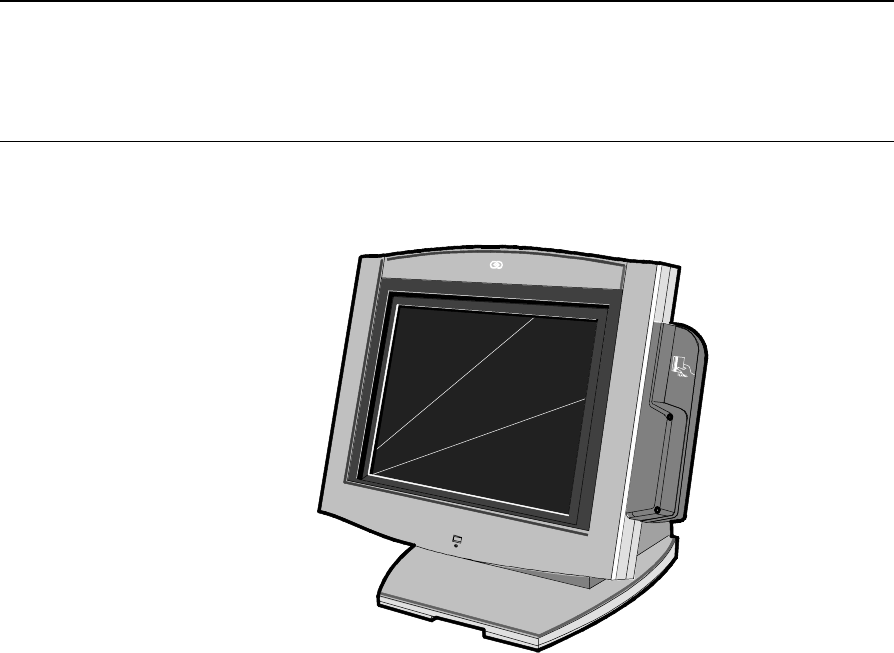
The major hardware features of the 7454 are a flat panel display with
touch screen input and LAN connectivity, plus optional magnetic
stripe reader, scanner, stereo audio, and wireless LAN.
The 7454 is Internet/Intranet ready. System loading can occur from a
network server, and software and data content are delivered from a
server through standard internet protocols.
1-2 Chapter 1: Product Overview
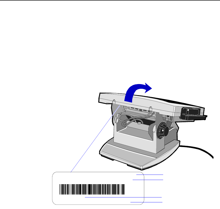
Serial Number/Model Number Label
The unit’s serial number, model number, tracer number, and date of
manufacture are included on a label on the back of the Core Module.
To view the label, tilt the Core Module and remove the cable cover.
Note: The serial number is repeated on the non-MSR side of the Core
Module.
NCR 7454-3504-M001
50-12345678
Mfg
Date: 11/15/01
F000,F017,F127,F503,F752,F009,F101,F601
Class/Model
Serial Number
Feature Number(s)
Date Manufactured
16394a

Chapter 1: Product Overview 1-3
Hardware Modules
Base Unit
• Processor Board
− Intel® Pentium® III or Celeron-class processor
− SVGA chipset
− MPEGII chipset
− 32 MB RAM on board (Celeron 600 MHz processor)
− 64 MB RAM on board (Celeron 700 MHz processor)
− 4 MB Video Memory
− 1 MB Flash BIOS (not CMOS)
− Four RS-232 ports (two optionally powered)
− 10/100BaseT Ethernet LAN chipset, Wake-on-LAN support,
and RJ-45 port
− PC Audio with an internal mono speaker
− Sound Blaster® 16-compatible audio chipset
− Two USB type A ports
− PS/2 keyboard port
− External VGA display port.
− External stereo speaker port
− Internal PS/2 mouse (dedicated to the touch screen)
− One SODIMM (Small Outline DIMM) RAM socket (32 MB)
− IDE support for a hard disk and an optional compact flash

1-4 Chapter 1: Product Overview
• POS Connector Board
− Cash drawer port (supports two drawers via a Y-cable)
− Internal parallel port (dedicated to the optional customer
display)
• 12.1-Inch Operator Display - capacitive or resistive touch LCD,
available in active matrix models
• 15-Inch Color TFT LCD Operator Display panel with capacitive
touch screen
• 2.5" hard disk
• Integrated Motion Sensor, capable of waking up the terminal from
a low power state
• Integrated Power Supply
• Reset switch which can be used to recover from a lock-up condition
• 3-meter Ethernet cable
• 85W Power Supply
• U.S. power cord
Hardware Options
• Intel Pentium III processor
• Intel Celeron (700 MHz) processor
• Integrated MSR (3-track ISO or JIS)
• Integrated Stereo Module
• Integrated Infrared Sensor
• Dual PCMCIA (for wireless LAN)
• Gray (G105) or Charcoal Gray (CG01) cabinet colors
• Mounting options: Table-top, Wall
• 7837 Hand-held Scanner

Chapter 1: Product Overview 1-5
• 7892 Bi-modal Presentation Scanner
• Customer displays
− No customer display
− Parallel
− Integrated 4x20 (low or high-post)
− Remote 2x20
− VGA (Dual Display)
− CRT (Kit)
− Analog LCD (Kit)
• 256 MB Compact Flash (IDE Bus)
• Cash drawers
− 2113 Cash Drawer (modular)
− 2189 Cash Drawer (modular)
− 2260 Cash Drawer (modular)
− Dual cash drawer cable
• 7454 Printers:
− 7158 Thermal Receipt/Impact Printer
− 7167 Thermal Receipt/Impact Printer
− 7194 Thermal Receipt Printer
− 7196 Thermal Receipt Printer
− 7197 Thermal Receipt Printer
− 2214 Thermal Fiscal Printer
− Remote printer cables
− Signal extenders for remote printers
• 2757 Kitchen Display System
• PC keyboard
− Keyboard Shelf

1-6 Chapter 1: Product Overview
• USB RS-232 Port Server
− USB Serial Converter
• CD-ROM Drive
Terminal Components not Supported
It is important to note that the terminal does not support the following
components.
Not supported Alternative implementation
CMOS for hard totals, logs, and
tallies Hard disk, compact flash, or server
storage
Removable media, e.g., a flex
disk LAN communication to an NT server
via standard protocols
SLP terminal loading Local storage, TCP/IP networking
and PXE loading
Keylock for security (X, L, R, S) Reset switch based security
ISA and PCI Expansion slots USB and LAN based devices (future)
DVD ROM
Internal UPS External UPS
Manual Video and audio
controls Software controlled
Windows® 3.1,
Windows NT® 3.51, OS/2 Windows NT 4.0, MS-DOS®,
Windows® CE, Windows® 95,
Windows® 98, Windows® 2000,
Windows® XPe
Intel 133 MHz, 166 MHz, and
266 MHz Pentium Processors
AMD 366 MHz and 400 MHz
Processors
Intel Pentium III 550 MHz
Intel Celeron® 600 MHz and 700 MHz
processors
Chapter 1: Product Overview 1-7
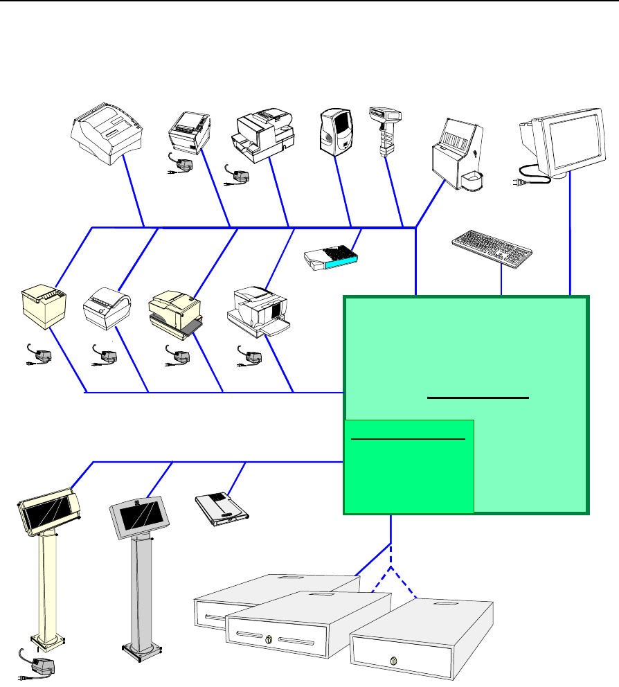
System Configuration Diagram
18470b
2260/2183/2189 2nd Cash Drawer
(Y-Cable)
5972/5973
PS/2 KBD VGA
POS Connector Bd.
USB
Audio
RS232 (4)
2 Optionally
Powered
Customer Display
(Parallel)
Cash Dwr
2336-K007
Ethernet
2336-K008
2113
7196 7166 2010 Coin
Dispenser
7892
2214
Processor Board
7837
5974
7194 7158
Note: 7158, 7167, 7194,
and 7197 are available in
both RS-232 and USB.
7167
7197

1-8 Chapter 1: Product Overview
Hardware Module Descriptions
Processor Board
Processor/Chip Set
The terminal uses an Intel architecture processor, which permits it to
leverage existing software drivers and applications, as well as provide
the greatest flexibility in choosing an operating system. This provides
several other advantages:
• Capable of SW MPEG-1 playback at 30 frames per second with 22
KHz stereo audio (may be limited by OS constraints)
• Sound Blaster-compatible audio capability
• Java Benchmark performance > 1000 Caffeinemarks, JIT compiled
• OS support to run Java
• Expansion capabilities for optional features and future
requirements (ISA/PCI bus and USB)
The following sections identify processors, system bus speed, and on-
board memory available on 7454 Release 2.x processor boards:
Release 2.0/2.1
• Intel 600 MHz µPGA2 Celeron Processor and 440BX chipset
consisting of the 82443BX (North Bridge) System Controller, also
called the MTXC, and the 82371EB (South Bridge) PCI ISA
accelerator, also called the PIIX4E.
• 100MHz system bus
• 32 MB memory with ability to add SODIMMS to increase the
memory capacity of the terminal
Release 2.2
• Intel 700 MHz Celeron Processor (BGA) on board, removing the
µPGA2 processor socket. Intel 440BX PC chipset same as in Release
2.0/2.1

Chapter 1: Product Overview 1-9
• 100MHz system bus
• 64 MB memory with ability to add SODIMMS to increase the
memory capacity of the terminal
Video Subsystem
The Release 2.x Motherboard uses the Silicon Motion (SMI) (LynxEM4
or LynxEM4+), with 4MB internal memory, 64 Bit memory bus, AGP
1x Support, 66MHz bus interface through AGP port, TFT panel support
up to 1280x1024.
The video subsystem supports the following LCD types:
• 12.1-Inch active matrix (TFT) 800x600 with 64 k colors
• 15-inch active matrix (TFT) 1024x768 with 262 k+ colors
Support for the LCD integrated display is provided internally. External
support for SVGA monitors (800x600) [or better] resolution and 64 K
[or better] colors) is provided by a CRT 15-pin D-shell connector.
The LCD brightness is software controlled. The terminal does not have
hardware controls for brightness or contrast.
The LCD back lighting is also software controlled. In addition to OFF
and ON modes, a dimmed mode is supported in the hardware to permit
increased tube life. If appropriate software drivers are loaded, full
brightness is restored when touched, motion detection (Motion Sensor
section), or an application request (i.e., to play promotional material on
a preset schedule).
Dual Displays
The Summa POS Motherboard is dual display (LCD and CRT) capable.
In a dual display environment the 7454 terminal supports 16-bit color
when both displays are connected to the motherboard. Both displays
must have the same maximum resolution capability. Refer to the
following information for details about the implementation of a dual
display configuration.

1-10 Chapter 1: Product Overview
• Lynx Family Control Panel Specification 1.2 on the NCR 74xx Base
System and Client Third party Drivers CD-ROM (Product ID:
D370-0111-0100) or in the video.exe self-extracting Video Drivers
file on the Retail Solutions Specific Third Party Products Drivers and
Patches web site at:
http://www.ncr..com/support/support_drivers_patches.asp?Class=retail_TPP.
• Retail Customer Information Display User’s Guide (BD20-1431-B) on
the NCR Information Products web site at:
http://www.info.ncr.com/eHome.cfm
Ethernet 10/100Base-T LAN Communications
The terminal contains a 10/100Base-T Ethernet PCI connection.
Ethernet 100Base-T is also known as Fast Ethernet. The Boot ROM for
diskless boot functionality is included in the 1 MB system ROM. The
hardware is compatible with the TCP/IP, DHCP, and TFTP protocols
required for remote boot of the platform. Appropriate software must
be used to enable each protocol used over the Ethernet link.
The terminal may be connected to either a 10 Mbps or 100 Mbps
Ethernet connection. The hardware automatically selects the correct
speed (if enabled by software to do so).
The LAN hardware supports wakeup packet capability as defined in
the Device Class Power Management Specification, Network Device
Class (available from the Microsoft® Web site).
When the platform is in the Soft OFF state (refer to Advanced Power
Management section that follows), receipt of a Wakeup Packet on the
LAN can return the system to the ON state, if this feature is enabled by
software.
Note: Due to limitations of the LAN controller and the OS, all features
described in the Network Device Class specification may not be
available.

Chapter 1: Product Overview 1-11
100Base-T is wired identically to 10Base-T, except that the twisted pair
cable must be Category 5 and the hubs must permit 100 or 10/100
Mbps operation. Although 10Base-T will operate on Category 3 twisted
pair, or NCR “747” cable, an upgrade to Category 5 is required for
100Base-T.
A customer desiring to use the terminal in an existing 10Base-T
environment can do so and simply run at 10 MB. In order to upgrade to
100Mbps, Category 5 cable and 100 or 10/100 hubs must be installed.
NCR strongly recommends the use of Category 5 for all new cabling,
even if the customer initially intends to run only 10Base-T.
LED Indicators for Link Integrity (verifies cable and hub connection are
good) and LAN speed is provided on the Processor Board near the row
of connectors at the bottom of the e-box. The LED is ON (yellow) when
the speed is running at 100 Mbps.
Link Integrity is provided to the PC chipset to permit boot-up software
to verify the presence of the LAN connection. Software must provide 2
seconds after power-up in order for the Link Integrity signal to become
valid.
Wireless LAN Communications
Where a wired Ethernet connection is not desired a wireless LAN
adapter may be installed in the PCMCIA socket. This requires that the
PCMCIA daughter-card feature be installed. A wireless LAN used in
the terminal must meet the following requirements:
• Integrated antenna that meets the requirements of PCMCIA (PC
Card) Extended Type 2 card definition (a maximum of 5-cm
additional length).
• Power consumption within the capabilities of the PCMCIA
daughter-card.
• Signaling requirements within the capabilities of the terminal
PCMCIA interface. The main restriction is that DMA transactions
are not supported over the PCMCIA interface.
• Device drivers for the targeted operating system must exist.

1-12 Chapter 1: Product Overview
• Appropriate infrastructure (server support, Base Stations, Ceiling
Antennas, etc) must be present in the installation site, and the
maximum RF range of the wireless system must not be exceeded.
Interoperability - While the 802.11 standard provides an interoperable
protocol definition, there are vendor-specific extensions to the protocol
that encourage users to stay with one supplier’s equipment. This also
applies to wireless infrastructure and access points, 802.11 does not
govern this operation. Mixing of RF suppliers on a site is not
recommended until the RF suppliers have demonstrated
interoperability.
The wireless networks operate at speeds of 1-11 Mbps with 2 percent
packet loss typical. The application developer must be aware of the
performance limitations and design applications that are acceptable to
the customer when run over the slower network.
Remote Wakeup over the wireless network is not possible because the
cards do not support it. An alternative is to use the system real-time
clock wake up at a scheduled time.
Depending on the OS environment, Remote Boot may be supported,
but due to the slow network speed a large boot image may take an
unacceptably long time to load. The application developer needs to
ensure that the load is of reasonable size.
The wired Ethernet connection is not certified for use in configurations
where a wireless adapter is installed.
Universal Serial Bus
The Summa POS Motherboard provides three ports, one of which is
reserved for integrated devices (not externally accessible). Only two of
the three USB ports on the Summa POS Motherboard can be active at
the same time. If the internal auxiliary USB port is enabled, one of the
two ports on the main connector row becomes disabled. This
functionality is controlled through the BIOS setup menu.
Note: USB peripherals require support from the operating system,
which is currently limited to Windows 98.

Chapter 1: Product Overview 1-13
Serial Ports
The Summa POS Motherboard provides two RS-232 ports (9-pin D-
shell connectors, Ports 1 and 2) directly on the Motherboard and
supports two additional RS-232 ports. Ports 3 and 4 require an optional
harness connection to the Motherboard. Ports 1 and 3 can be supplied
with +12 V DC on Pin 9 when properly set up in the BIOS. The total
power drawn by Ports 1 and/or 3 must be no greater than 1 amp at +12
V DC. Refer to the following table for RS-232 pinout information.
The BIOS provides flexibility in mapping resources. However, a fully-
loaded system (2 PCMCIA cards that require IRQs, four serial ports in
use, USB in use, parallel port in use, and MSR) may not have enough
available IRQs to support all serial ports. Use a USB serial port
expander to overcome this PC architecture limitation.
RS-232 DB-9 Male Connector Pinout
Pin Port A Port B
1DCD DCD
2RXD RXD
3TXD TXD
4DTR DTR
5GND GND
6DSR DSR
7RTS RTS
8CTS CTS
9RI or +12*
VDC
RI
* If Port 1 or 3 is powered, pin 9 will be +12 V.
Hardware Monitor
The hardware monitor generates an interrupt to the system whenever
any of the internal voltages used by the system processor goes above or
below the acceptable operating range. An interrupt is also generated
when the temperature of the Processor exceeds safe levels. Software
can use this indication to slow or stop the system and/or force a reset.

1-14 Chapter 1: Product Overview
PCI Expansion Header
A single expansion header is provided to support optional features,
such as the PCMCIA for Wireless LAN Board. This board supports two
Type 2 or one Type 3 PCMCIA type cards.
IDE Header
A standard IDE header is provided to support the 2.5" hard disk drive
or the 64 MB and 256 MB compact flash.
Audio
The base unit has Sound Blaster-compatible audio. Wave table
synthesis is not supported. FM synthesis and MIDI are supported in
the hardware, but requires software driver support to function.
Higher quality integrated stereo speakers may be added as an option to
the terminal. The amplifier is located on the Processor Board; the
speaker output is provided on a header that receives the harness from
the speaker module. In addition, a Line Out is provided on a 3.5mm
stereo jack that permits connection of external amplified speakers.
The integrated stereo speakers, or an amplifier connected to Line Out,
must be used in order to play Sound Blaster (audio subsystem) audio.
However, an internal EUI speaker provides PC speaker functionality
(beeps and tones) for all configurations.
The volume control can be set during system configuration.
The PC speaker sounds (such as beeps and touch clicks) are directed
into the audio subsystem and are audible if speakers are connected.
Magnetic Stripe Reader
A 3-track MSR head is available as an option. The ISO and JIS card
format is supported.
When card data is read, an interrupt is generated. A software device
driver for the MSR must be loaded to enable the application to process
the data.

Chapter 1: Product Overview 1-15
Touch Screen Controller
The MicroTouch® “Excalibur” chip is used to interface the touch panel.
This controller supports MicroTouch capacitive panels.
In order to save an RS-232 port, the touch data is delivered to the
system through the mouse interface. This requires a mouse-aware
touch device driver for the appropriate OS.
When the system is operating in the dimmed display mode, touch
activity can restore full brightness if instructed by software to do so.
When system is in low power mode, touch activity can generate the
mouse port interrupt (IRQ12).
The Summa POS Motherboard supports the following touch screen
LCDs;
• Sharp TFT LCD/capacitive touch screen (F002)
• Sharp TFT LCD/resistive touch screen (F004)\
• 15-inch LG TFT LCD/capacitive touch screen (F008)
Processor Board Connectors
All connectors are either keyed or impossible to plug incorrectly due to
mechanical design of the product.
External Connectors Internal Connectors
VGA CRT RGB 15-pin D Shell LCD
Ethernet RJ45 Back light Inverter
Dual USB Type A Integrated Speaker Module
External Stereo speaker
(3.5mm jack) MSR
Power supply Touch screen (PS/2)
RS-232 9-pin D shell (two, one
with +12 V power option)
PS/2 Keyboard Motion Sensor / Power Indicator
Customer Display PCI Expansion header

1-16 Chapter 1: Product Overview
External Connectors Internal Connectors
Cash Drawer IDE
20-pin high density RS-232
Conversion connector Parallel port (POS Board header)
Microphone Cash Drawer port (POS Board header)
S-Video
Compact Flash
The optional compact flash replaces the hard drive in the unit. The
64MB compact flash is large enough to support a Windows CE load.
The 256MB compact flash can be used in a Windows XP embedded
environment. When using the Windows XP embedded OS, an
additional 128MB SDRAM SODIMM is required to support the
necessary virtual memory requirements.
NCR Retail Specific Hardware
The Processor Board contains logic that provides support for the
custom retail interface. The logic controls the following features:
• Dual Cash Drawer Support
• Cash Drawer Diagnostic Support
• Magnetic Stripe Reader Interface
• Motion Detector
• Touch Screen Interface
An integrated retail specific feature of the processor is the cash drawer
circuitry. The onboard circuitry internal to the board provides the
control for two external cash drawers. A portion of the POS Board
header (J6) is provided on the board to interface to the dual cash
drawer connector. Header J6 only contains the control signals; it does
not provide power. Software controls the cash drawer(s) through I/O
port 00Exh. This means it can be I/O ports E0/E1h, E2/E3h, E4/E5h,
or EA/EBh depending on the configuration of the SMC I/O
controller’s GPIO port(s). Default setting is E0/E1h.

Chapter 1: Product Overview 1-17
Cash Drawer I/O Port Bit Definition:
Bit # Description Bit = 1 Bit = 0
7 Solenoid B Control Turns off solenoid
output Activates solenoid
output
6 Solenoid A Control Turns off solenoid
output Activates solenoid
output
5 Reserved Reserved Reserved
4 Reserved Reserved Reserved
3 Solenoid B Status Solenoid B output
active Solenoid B output
inactive
2 Solenoid A Status Solenoid A output
active Solenoid A output
inactive
1 Reserved Reserved Reserved
0 Cash Drawer(s) Status Drawer(s) open Drawer(s) closed
Note: Bits 2 and 3 are set to ‘1’ by each device reset.
The cash drawer interface can be diagnosed remotely. For security
reasons, the cash drawer diagnostics mode must first be activated by
pressing an external momentary switch (SW2). The intention is for
authorized personnel to be present when the cash drawer diagnostic
tests take place.
There is only one cash drawer status signal; therefore, bit 0 is the status
of either cash drawer or both cash drawers.
Power LED
The Processor Board provides support for an external power LED
through the onboard Motion/Power LED connector. This LED is
controlled through the SMC 37C935 GPIO pins. Once the SMC chip is
programmed to support the Power LED function on GPIO pin 13, the
LED is turned “on” anytime all power to the Processor Board is good.
The system’s power management software has the option to turn the
LED off indicating the system is in a power-managed mode.

1-18 Chapter 1: Product Overview
MSR
The MSR interface supports a maximum of 3 tracks of magnetic stripe
information for support of ISO or JIS format cards. Activate the MSR
interface by enabling it in BIOS Setup under IO Configuration. The
MSR interface controller is a memory-mapped device, which can reside
at system memory addresses CA000, CC000, or D0000. If MSR
capability is not desired, it may be disabled through BIOS Setup.
Board BIOS
The Processor Board uses a Phoenix BIOS, which is stored in Flash
ROM and easily upgraded through the network connection or serial
port. The Flash EEPROM also contains the Setup utility, Power-On Self
Tests (POST), and APM 1.2. The board also supports system BIOS
shadowing, which enables the BIOS to execute from onboard write-
protected DRAM.
The BIOS displays a sign-on message during POST identifying the type
of BIOS and a five-digit revision code.
FLASH memory Implementation
The Intel E28F800B5-T70 Flash component is organized onboard as
1024 K x 8 (1 MB). While a typical PC BIOS image including video and
LAN boot ROM code normally fits in 256 K on the Pentium Board and
512 K in the Pentium III/Celeron board, the boards support a 1 MB
flash ROM. The current Phoenix BIOS release only requires 256 K of
this 1 MB total. The Flash device contains the PC System BIOS along
with the Video BIOS and LAN boot ROM which compresses the ROM
images into a single binary image.
The Flash device is divided into four areas, as described below.
System Address FLASH Memory Area
F0000H FFFFFH 64 K Main BIOS
EE000H EFFFFH 8 K System BIOS Reserved during boot
ED000H EDFFFH 4 K Plug and Play ESCD Storage Area
E0000H ECFFFH 52 K System/VGA BIOS Reserved during boot

Chapter 1: Product Overview 1-19
BIOS Upgrades
Flash memory makes distributing BIOS upgrades easy. A new version
of the BIOS can be installed from the hard disk, network or through a
serial port.
The disk-based Flash upgrade utility, PHLASH.EXE, ensures the
upgrade BIOS extension matches the target system to prevent
accidentally installing a BIOS for a different type of system.
Setup Utility
The ROM-based Setup utility permits the system configuration to be
modified without opening the system for most basic changes. The
Setup utility is accessible only during the Power-On Self Test (POST)
by pressing the <F2> key after the POST memory test has begun and
before boot begins. A prompt may be enabled that informs users to
press the <F2> key to access Setup.
Note: An external alphanumeric keyboard is recommended for
running the BIOS CMOS Setup Utility. Otherwise, a Touch Screen can
be used.
Plug and Play
The Processor BIOS also has a setup option to support the Windows
runtime plug and play utilities. When this option is selected, only
devices critical to boot are assigned resources by the BIOS. Device
Node information is available for all devices to ensure compatibility
with Windows 95. System configuration information is stored in ESCD
format. The ESCD data is cleared upon loss of the CMOS voltage.
Advanced Power Management
The Processor BIOS has support for both 1.1 and 1.2 Advanced Power
Management (APM). The version of APM drivers loaded in the
operating system by the user determines what specification the BIOS
adheres too. In either case the energy saving Standby mode can be
initiated by a keyboard hot key sequence or a time-out period set by
the user.
1-20 Chapter 1: Product Overview
When in Stand-by mode, the Processor Board reduces power
consumption by utilizing the processor System Management Mode
(SMM) capabilities and also spinning down hard drives and turning off
VESA DPMS compliant monitors. During setup, the user may select
which DPMS mode (Stand By, Suspend, or Off) is sent to the monitor.
The ability to respond to external interrupts is fully maintained while
in Stand-by mode enabling the system to service requests such as in-
coming data or network messages while unattended. The user may
also select any keyboard or mouse activity to take the system out of the
energy saving Standby mode. When this occurs, the monitor and IDE
drives are turned back on immediately.
APM is disabled in BIOS by default; therefore, the user must enable
this feature. The system must be configured with an APM driver in
order for the system power saving features to take effect.
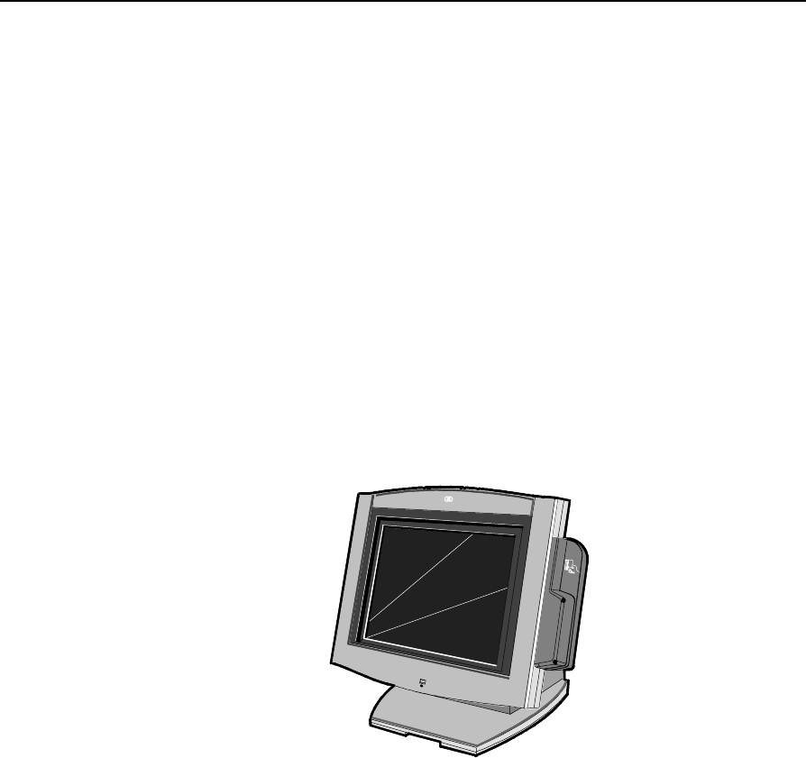
Operator Display
18004
NCR
The 7454 is available with two LCD types
• 12.1-Inch TFT (active matrix) 800x600 with 64K colors
• 15-inch TFT (active matrix) 1024 x 768 with 262K+ colors

Chapter 1: Product Overview 1-21
Contrast control is set by software, using a digital potentiometer on the
Processor Board. The terminal does not have a user-accessible contrast
adjustment. Software can set a default value after reading the Panel ID.
Display contrast changes with temperature.
LCD Adapter Board
The signals from the LCD header on the Processor Board are brought
to the LCD on a harness. Since there are multiple pin configurations
and connector types being used on the LCD, a small adapter board is
used to receive the LCD harness and map the signals into the correct
pinout for the LCD panel. This board has a connector that plugs
directly into the LCD panel.
LCD Backlight Inverter Module
An Inverter Board supplies power for the LCD Backlight, which is a
separate module in the terminal. The inverter has a connector that
receives power, ground, and a Backlight dimming signal from the
Processor Board. The inverter generates the high voltage necessary to
start and run dual CCFL Backlights.
A fuse located on the Inverter Board protects power to the inverter.
This fuse protects the system from damage in the event of a Backlight
or Inverter Board fault. The fuse is not field replaceable; if it blows, the
safety characteristics of one or more components on the Inverter Board
may have been compromised and the Inverter Board should be
replaced.
If one or both Backlight tubes become disconnected or otherwise open-
circuited, protection circuitry shuts down the inverter. This avoids
over-powering a single tube and also protects against high voltage
shorting.
1-22 Chapter 1: Product Overview
Touch Screen
The Touch Screen completely covers the LCD and is mounted directly
in front of the LCD, behind the front plastic bezel of the terminal. The
touch controller on the Processor Board supports capacitive and
resistive touch glass.
The touch glass has an integrated harness that is routed into the
Processor Board enclosure and is connected to a header on the
Processor Board. The touch glass has a glare-reducing texture that also
helps hide fingerprints.
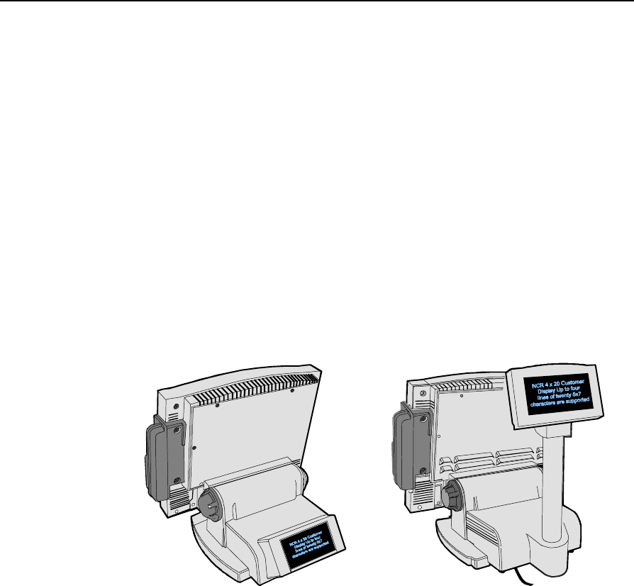
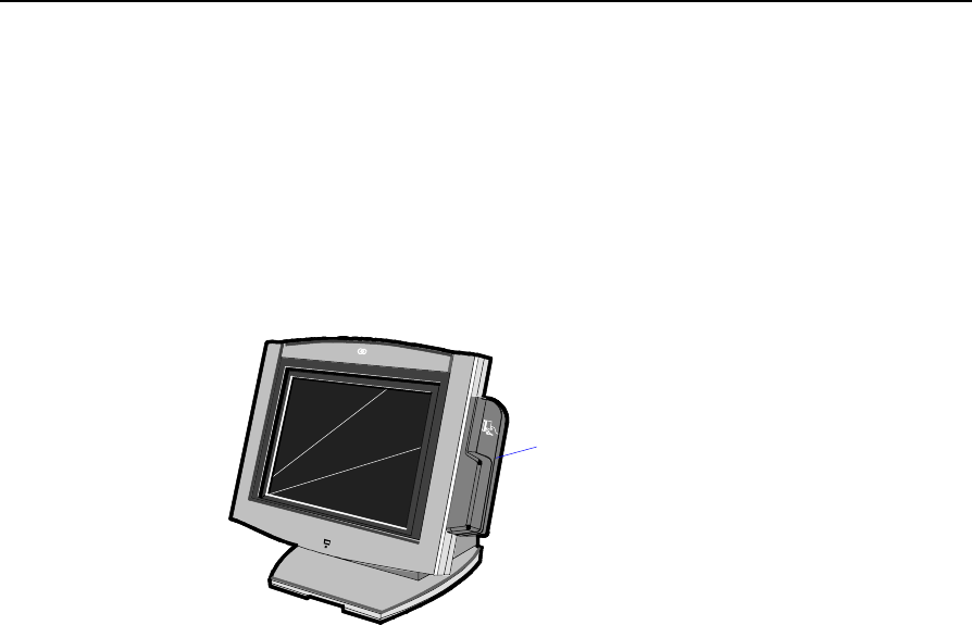
NCR 7454 Integrated Customer Display
The NCR 7454 Integrated Customer Display supports four lines of
twenty 5x7 characters. It is available in a low profile or high-post
model.
16949
The 7454 Retail Terminal also supports these remote customer
displays:
• NCR 7454 4x20 Customer Display. This display uses the same
display module as the 7454 Integrated Customer Display.
• NCR 5972-1100 Vacuum Fluorescent Display (VFD). This display
uses a parallel port.
Chapter 1: Product Overview 1-23
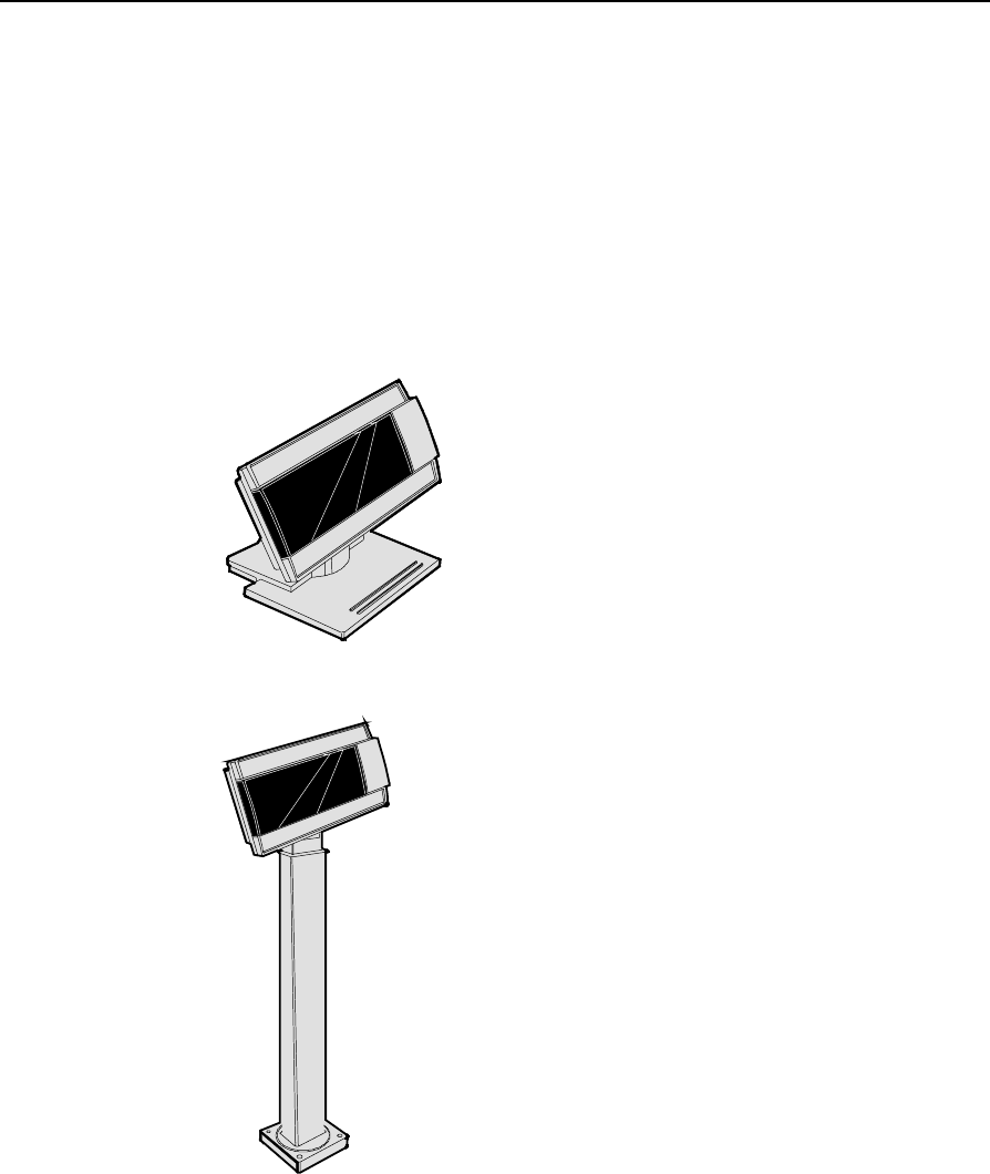
NCR 5973 International VFD Customer Display
The NCR 5973 VFD (Vacuum Fluorescent Display) is an optional
display device for the 7454 Retail Terminal. The VFD is available in
models that have a combination of:
• Dark gray cabinetry
• Mounting configurations
• System specific cables
Table Top Mount
12271
16" High Post Mount
17198
1-24 Chapter 1: Product Overview
Features
Magnetic Stripe Reader
A single 3-track analog Magnetic Stripe Reader (MSR) is available as a
feature, supporting ISO and JIS format cards. When the MSR is not
desired, a filler piece for the MSR section is included to make the unit
appear uniform.
18286
NCR
MSR
Chapter 1: Product Overview 1-25
Printer OptionsThe sections that follow provide an illustration and brief description of
the available printer options.
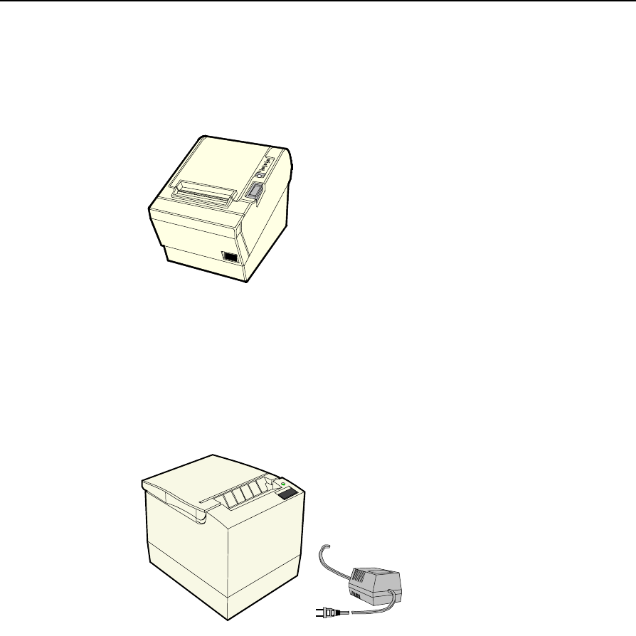
2214 Printer
The 2214 Printer is a thermal fiscal printer that can issue tickets and
produce a journal. Its power cord plugs into a 120 VAC power source
and the included RS-232 cable connects the printer’s serial connector to
the workstation.
18541
1-26 Chapter 1: Product Overview
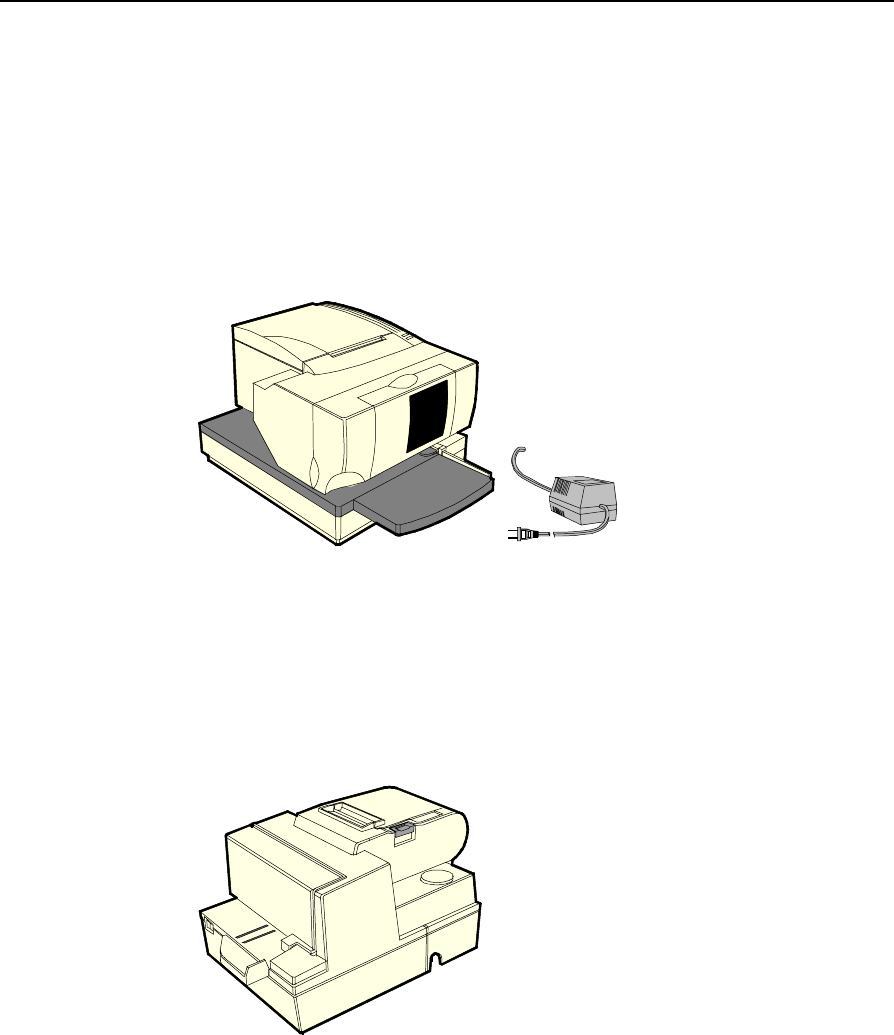
7158 Printer
The 7158 Printer is extremely fast, quiet, and reliable point-of-sale
device. It consists of two specialized printers in one compact package:
a thermal printer on top that prints receipts, and an impact slip printer
in front to print on forms and checks that you insert. It receives its
power from an external power supply, can be connected through a
USB or serial port, and has a connector for cash drawers.
17304c
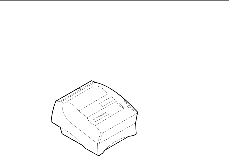
7166 Printer
The 7166 Printer is an extremely fast, quiet, and reliable point-of-sale
printer. It consists of two specialized printers in one compact package:
a thermal printer that prints receipts, and an impact slip printer. It
receives its power from an external power supply, has a serial interface
and a connector for cash drawers.
17303
Chapter 1: Product Overview 1-27
7167 Printer
The NCR 7167 Printer is a fast, quiet, relatively small and very reliable
multi-function printer. It prints receipts, validates and prints checks,
and prints on a variety of single or multiple part forms. There is no
journal as it is kept electronically by the host terminal. The printer
features a dual interface, so it can connect to the host terminal either
through a USB or RS-232 connector. It receives its power from an
external power supply, and has a connector for cash drawers.
19711e
7194 Printer
The 7194 Printer is a high speed, high-resolution printer, capable of
both text and graphics printing. It offers direct thermal printing in a
receipt station. It receives its power from an external power supply,
can be connected through a USB or serial connector, and has a
connector for cash drawers.
16437
1-28 Chapter 1: Product Overview
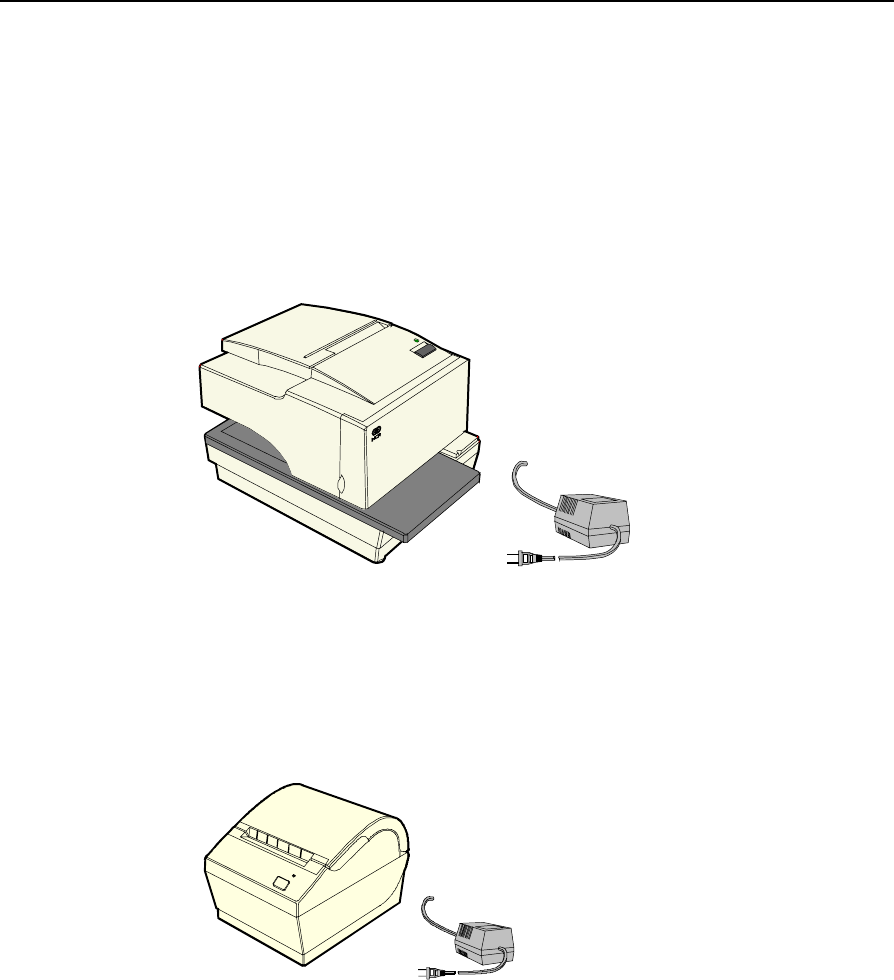
7196 Printer
The 7196 Printer is a high speed, high-resolution printer, capable of
both text and graphics printing. It receives its power from an external
power supply, has a serial interface and a connector for cash drawers.
17302
7197 Printer
The NCR 7197 Printer is a fast, quiet, relatively small and very reliable
multi-function printer. It prints receipts and two-color printing. The
printer features a dual interface, so it can connect to the host terminal
either through a USB or RS-232 connector. It receives its power from an
external power supply, and has a connector for cash drawers.
19712e
Chapter 1: Product Overview 1-29
Other Integrated Devices and Indicators
Hard Disk Drive
A 2.5" IDE hard disk is available. The drive is the standard type that is
used by notebook PCs.
Reset Switch
The Reset Switch is provided as a last resort to reboot the system if the
software reset port mechanisms fail. This switch is located on the row
of connectors that are located at the bottom of the enclosure. Although
not intended to be easily accessible, the reset switch can be operated
without removing covers or using any special tools.
16454
Reset Switch
Reset Procedure
1. Press the Reset Switch and hold it in for more than 4 seconds. The
screen goes blank.
2. Press the Reset Switch again. The system then reboots.
Internal Speaker
The Internal Speaker is connected to the PC speaker output of the
system chipset, not to the audio subsystem. It is connected to the
Processor Board via a harness and mounted inside the Processor Board
enclosure.
1-30 Chapter 1: Product Overview
POS Connector Board
The POS Connector Board is a small daughter board that mounts
directly on the Cash Drawer and Parallel Port header. Connectors on
the edge of this board form a second connector row above the
Processor Board connectors. Connectors are available for two cash
drawers, a customer display and a microphone.
Power for the cash drawers (24 V) and VFD customer display (5 V and
12 V) is supplied by the Enhanced Power Supply through the parallel
connector.
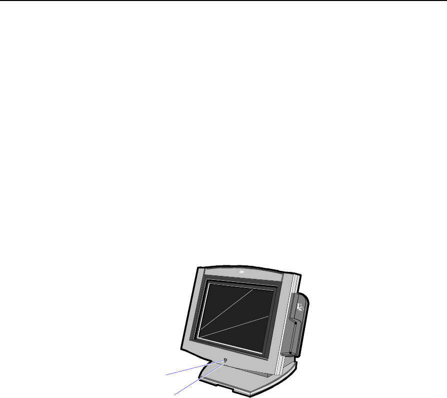
Motion Sensor
The terminal hardware can detect movement near the terminal and
enables software to prompt system operation from a low-power state.
Application software may also be able to make use of motion detection
when in the ON state if it is enabled by lower-level software.
18287
NCR
Motion Sensor
Power/Status LED
Motion is detected as a change in ambient light level that is greater
than a software-controlled threshold.
A photodiode mounted behind the front bezel of the unit senses
ambient light levels. The photodiode resides on a small circuit board
(the Motion Sensor Board). A harness connects the Motion Sensor
Board to the amplifier and motion sensing logic on the Processor
Board. The user Power/Status LED indicator shares this board.

Chapter 1: Product Overview 1-31
Power/Status LED
The LED power indicator indicates that power is present. The LED is
green when the processor and BIOS are operating properly. The LED is
mounted behind the front bezel on the same board as the motion
sensor.
Power OK LED
The Power OK LED is located behind the Cable Cover, between the
Customer Display and Cash Drawer connectors.
16453
Power OK LED
(5V and 24V)
LAN Status LEDs
16455
LAN Integrity
(Green)
LAN Speed:
Yellow = 100 MB
OFF = 10 MB

1-32 Chapter 1: Product Overview
Power Supply
The terminal uses an AC adapter for its power supply, concealed in the
terminal mounting. The supply is inaccessible when the terminal is in
the normal operation and mounting position to prevent tampering, and
sealed to help protect against spills or other environmental hazards.
Note: The power supply automatically senses the proper AC voltage;
therefore only normal servicing access is required.
All power required to operate the base unit, PCMCIA option and
PCMCIA cards, speaker option, scanner option, and bus-powered USB
peripherals is provided by the power supply.
The Processor Board serves as the hub to distribute power to all
terminal functions. Cash drawers, VFD customer display, PS/2
keyboard, PCMCIA daughter board and slots, scanner (through RS-232
port), USB, hard disk, and the LCD all receive power through their
respective Processor Board connectors.
Integrated Speaker Module (Optional)
The Integrated Speaker feature provides two stereo speakers that
attach to the bottom of the Core Module. The maximum output of the
speakers is approximately 6 watts per channel.
Chapter 1: Product Overview 1-33
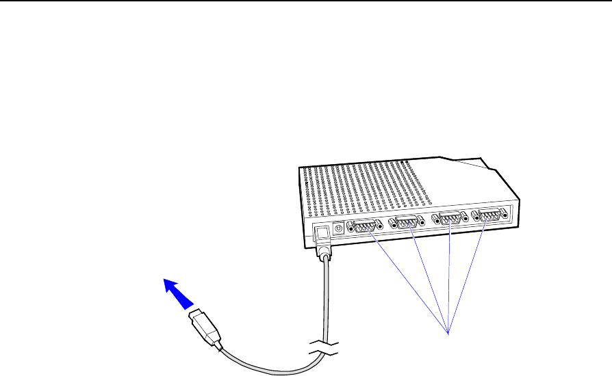
USB RS-232 Port Server
The USB RS-232 Port Server is an intelligent, stackable expansion
module that connects to the terminal Universal Serial Bus (USB) port,
providing high-speed RS-232 serial ports.
7454/7401
USB Port
RS-232 Ports
16944
1-34 Chapter 1: Product Overview
Additional Pentium III and Celeron Connectors
The Pentium III and Celeron board has an IRDA connector that is not
on the Pentium board. It is not used at this time.
A connector can be added on Pentium III and Celeron models to add
two additional RS-232 ports. To add the ports, install the Dual RS-232
Port Kit (7454-F072) as described in the Feature Kits appendix.
The following illustration shows the RS-232 Connector, which is part of
the Dual RS-232 Port Kit, installed on the Connector Row Bracket.
19106
IRDA
(Not used)
RS-232 Connector
(COM 3 and COM 4)
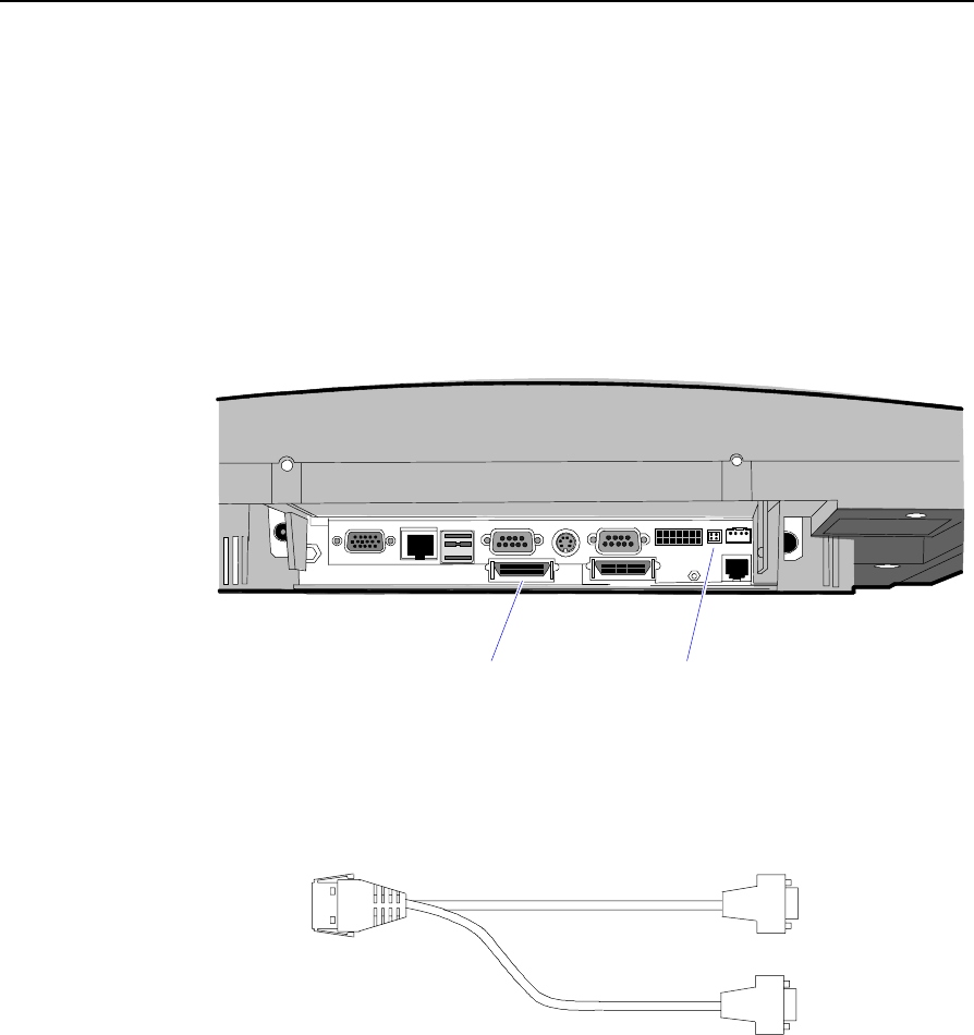
The Dual RS-232 Port Kit also includes the Dual RS-232 Cable. When
this cable is plugged into the Interface Cable Connector, the two
additional serial ports are available.
18002

Chapter 2: Hardware Installation
Introduction
The terminal is fully assembled at the factory. This chapter explains the
mounting options and how to connect optional hardware components
to the terminal.
Installation Summary
The terminal should be removed from the shipping packaging and
visual checks made to verify the correct hardware configuration. The
system is then configured and any communication cables are
connected.
Only after inspection should the power cord be attached to the system
and then connected to the AC power source. Power-up self-tests will
run to verify basic functionality.
ROM-based setup should be used to configure network options. Full
configuration depends upon the system server and the management
Web site.

2-2 Chapter 2: Hardware Installation
Installation Restrictions
• Before installing the terminal, read and follow the guidelines in the
NCR 7454 Retail Terminal Site Preparation Guide and the NCR
Workstation and Peripheral AC Wiring Guide.
• Install the terminal near an electrical outlet that is easily accessible.
Use the power cord as a power-disconnect device.
• Do not permit any object to rest on the power cord. Do not locate
the terminal where the power cord can be walked on.
• Use a grounding strap or touch a grounded metal object to
discharge any static electricity from your body before servicing the
terminal.
• If the power cord is replaced, it must be replaced with the same
type of cord with the protective shroud.
• Do not route the power cord through openings with sharp edges.
Caution: This unit contains hazardous voltages and should only be
serviced by qualified service personnel.
Caution: DO NOT connect or disconnect the transaction printer while
the terminal is connected to AC power. This can result in system or
printer damage.
Warning: The 7454 must be mounted securely to prevent a hazard. It
must be installed in accordance with local building codes. The post or
wall on which the unit is mounted should be able to withstand four
times the weight of the unit, which is approximately 20 lbs. (9 kg).
Chapter 2: Hardware Installation 2-3
Connecting the Cables
Tilt Mount cable connectors are located on the underside of the Core
Module, under a cable cover.
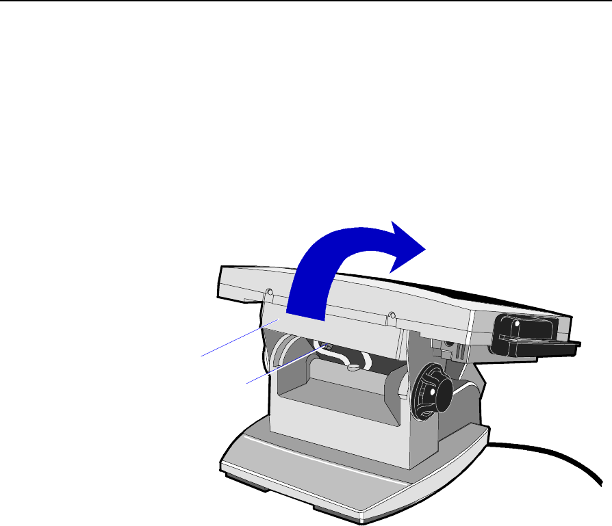
Accessing the Cable Connectors
1. Tilt the display to access the cable connectors.
Cable Cover
Thumb Screw
15968
2. Loosen the thumbscrew that secures the Cable Cover and remove
the cover.
2-4 Chapter 2: Hardware Installation
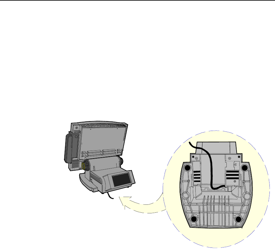
Routing the Cables
The 7454 has three places to secure cables to the base of the unit by
using a cable tie wrap. Remove the power supply cover or customer
display from the base of the unit, two thumb screws on bottom rear,
and use a tie wrap to secure the Ethernet cable to one of the provided
molded cable tie holders on the base. This should provide sufficient
strain relief to prevent the cable from becoming tight and damaging the
connector on the Processor Board.
The peripheral cables are routed down through the Mount Assembly
and out the rear of the unit.
16413a
Bottom View
Chapter 2: Hardware Installation 2-5
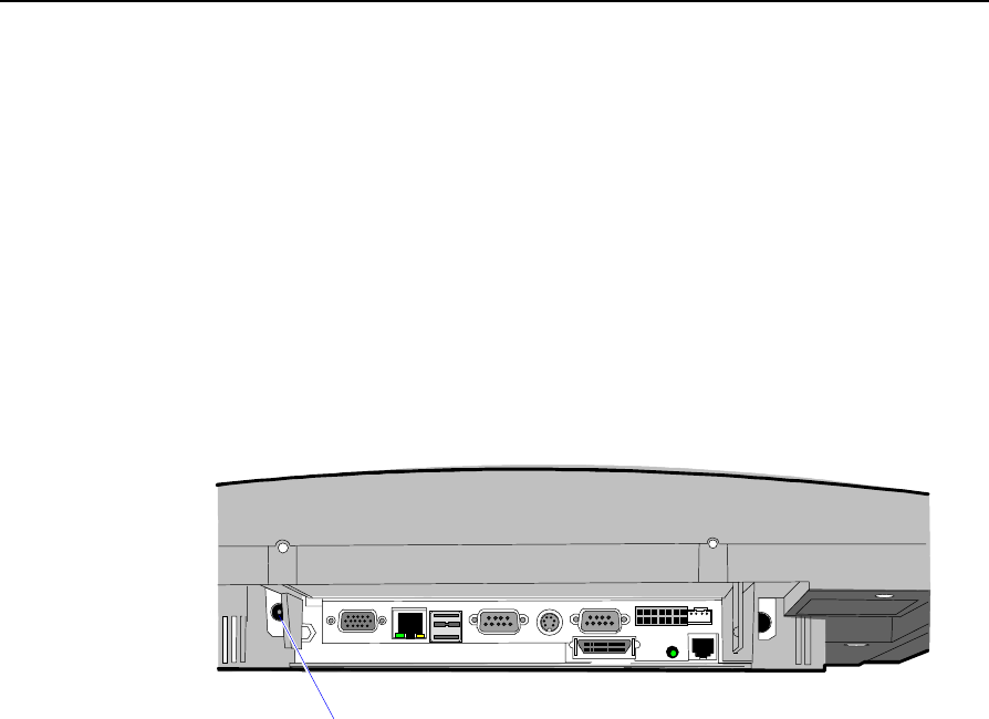
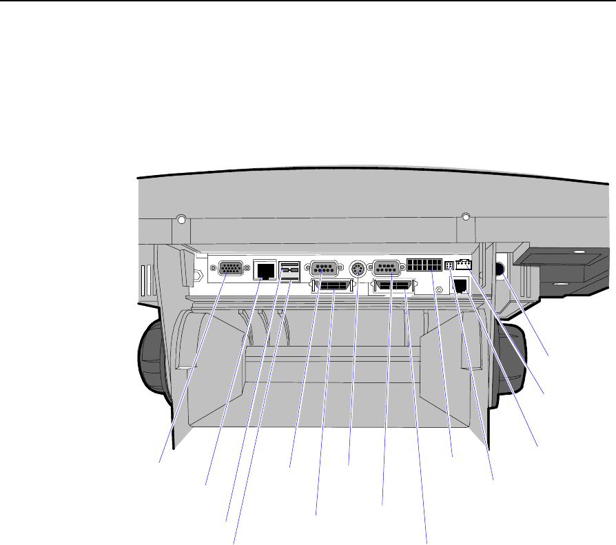
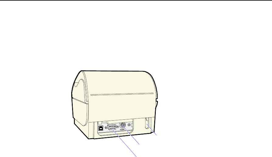
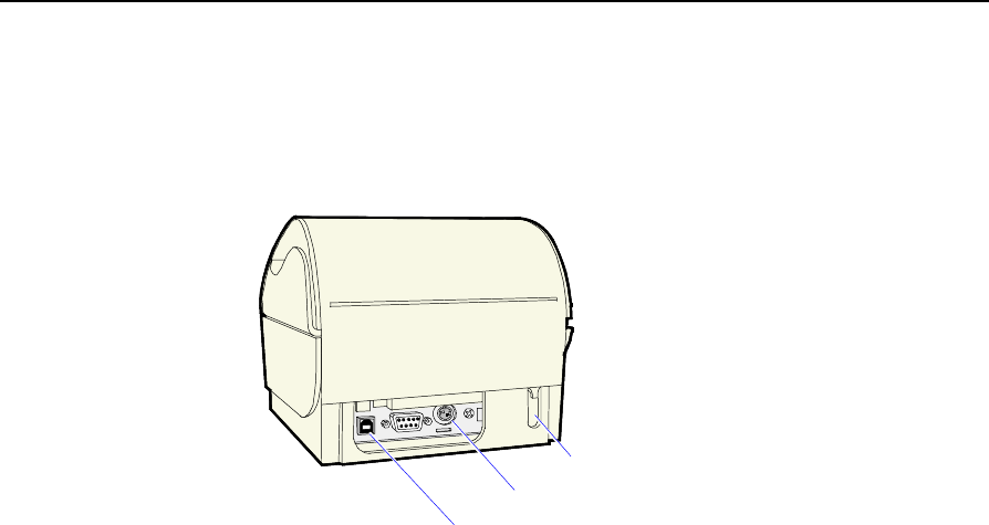
Identifying the Cable Connectors
The following illustration identifies each of the cable connectors. Refer
to the sections following the illustration for specific instructions on
installing each peripheral. After installing the peripheral and LAN
cables, replace the cable cover and tighten the thumbscrew.
19107
CRT
LAN
USB 1
COM 1
COM 2
Keyboard
PS/2
Parallel
Power
Audio Out
Cash Drawer
Speaker
RS-232
(COM 3 & 4)
IRDA (not used)
Microphone
(optional)
USB 2
Note: COM1 and COM3 are powered ports.
Note: The COM3 & COM4 RS-232 ports require the Dual RS-232 Port
Kit (7454-F072) feature

2-6 Chapter 2: Hardware Installation
Installing Peripherals
This section describes how to install transaction printers and other
peripherals on the 7454 terminal.
Installing a Transaction Printer
Transaction printers can connect through a non-powered RS-232 or
USB connector as defined in the table below. Each printer except the
2214 requires an external power supply. The illustrations show how to
connect to the 7194 printer. Connecting to the other printers is done in
the same manner. Refer to the corresponding printer owner’s manual
for illustrations of the connector locations.
Printer Type RS-232 USB
2214 Thermal Fiscal √
7158 Thermal Receipt/Impact Slip √√
7166 Thermal Receipt/Impact Slip √
7167 Thermal Receipt/Impact Slip √√
7194 Thermal Receipt √√
7196 Thermal Receipt √
7197 Thermal Receipt √√
Owner’s Manuals/Guides
• NCR 7158 Thermal Receipt/Impact Printer Owner’s Guide
(B005-0000-1112)
• NCR 7166 Multifunction Printer Setup & User’s Guide
(B005-0000-1002)
• NCR RealPOS 7167 Two-Station POS Printer Owner’s Manual
(B005-0000-1406)
• NCR 7194 Thermal Receipt Printer Owner’s Guide (B005-0000-1097)
• NCR 7196 Thermal Receipt Printer Operator Manual (B005-0000-1171)
• NCR RealPOS 7197 Receipt Printer Owner’s Manual (B005-0000-1409)
Chapter 2: Hardware Installation 2-7
RS-232 Installation
1. Connect the Printer Interface Cable to the RS-232 Connector on the
back or on the bottom of the printer.
16632a
RS-232 Connector
Power Connector
Cash Drawer Connector
2. Connect the other end of the printer cable to one of the RS-232
(non-powered) ports on the terminal.
3. Connect the external power supply cable to the Power Connector on
the printer.
4. Plug the external power supply AC cable into an AC outlet.
2-8 Chapter 2: Hardware Installation
USB Installation
1. Connect the Printer Interface Cable to the USB Connector on the
back or on the bottom of the printer.
16632b
USB Connector
Power Connector
Cash Drawer Connector
2. Connect the other end of the printer cable to one of the USB
connectors (USB 1 or USB 2) on the terminal.
3. Connect the external power supply cable to the Power Connector on
the printer.
4. Plug the external power supply AC cable into an AC outlet.
Chapter 2: Hardware Installation 2-9
2214 Printer
1. Connect the Printer Interface Cable to the RS-232 Connector on the
back of the printer.
18543
RS-232
Connector
Printer Interface
Cable
2. Connect the other end of the Printer Interface Cable to an RS-232
port (non-powered) on the terminal.
3. Plug the Power Cord into an AC outlet.
2-10 Chapter 2: Hardware Installation
Installing a Remote Customer Display
The terminal supports three high-post remote customer displays. The
mounting configuration is the same and appearance is similar:
• 5974 Remote Customer Display (4x20 characters, VFD)
• 5972-1000 Remote Customer Display (2x20 characters, VFD)
• 5973 International VFD Customer Display
5974 Remote Customer Display
16670
1. Place the Display Mount on the desired surface within or 4 meters
(13 feet) of the host terminal.
2. Determine if the cable should be routed down through the
mounting surface or if it should be run on top of the surface.
Chapter 2: Hardware Installation 2-11
3. Secure the Mounting Plate with 4 screws provided.
16671
Mounting Plate 4 Holes
0.40 mm
(0.16 in.)
Diameter
76 mm
(3 in.)
4. Connect the Display Cable to the Customer Display port on the
terminal.
15969b
Customer
Display

2-12 Chapter 2: Hardware Installation
5972-1100 Remote Customer Display
16257
1. Place the Display Mount on the desired surface within 4 meters (13
feet) of the host terminal.
2. Determine if the cable should be routed down through the
mounting surface or if it should be run on top of the surface.
3. Secure the Mounting Plate with 4 screws provided.
16258
Mounting Plate 4 Holes
0.40 mm
(0.16 in.)
Diameter
76 mm
(3 in.)
Chapter 2: Hardware Installation 2-13
4. Connect the 5972 Display Cable to the Parallel I/F Adapter Cable.
16291a
Customer
Display
5972 Display Cable
497-0405676 - 4 M
1416-C278-0040
Parallel I/F Adapter Cable
497-0411000 - 0.6 M
1416-C472-0006
7454 Cust.
Display Port
Power
Brick
5. Connect the Parallel I/F Adapter Cable to the Customer Display
port on the terminal.
15969b
Customer
Display
6. Connect the 5972 Display Cable Power Brick connector to the
Power Brick cable.
7. Plug the Power Brick into an AC outlet.
2-14 Chapter 2: Hardware Installation
5973 International VFD Customer Display
14528
(4) Screws
1. Place the Display Mount on the desired surface within 4 meters (13
feet) of the host terminal.
2. Determine if the cable should be routed down through the
mounting surface or if it should be run on top of the surface.
2. Secure the Mounting Plate with 4 screws provided.
16258
Mounting Plate 4 Holes
0.40 mm
(0.16 in.)
Diameter
76 mm
(3 in.)
Chapter 2: Hardware Installation 2-15
3. Connect the 5973 Parallel Cable to the Customer Display port on
the terminal.
15969b
Customer
Display
2-16 Chapter 2: Hardware Installation
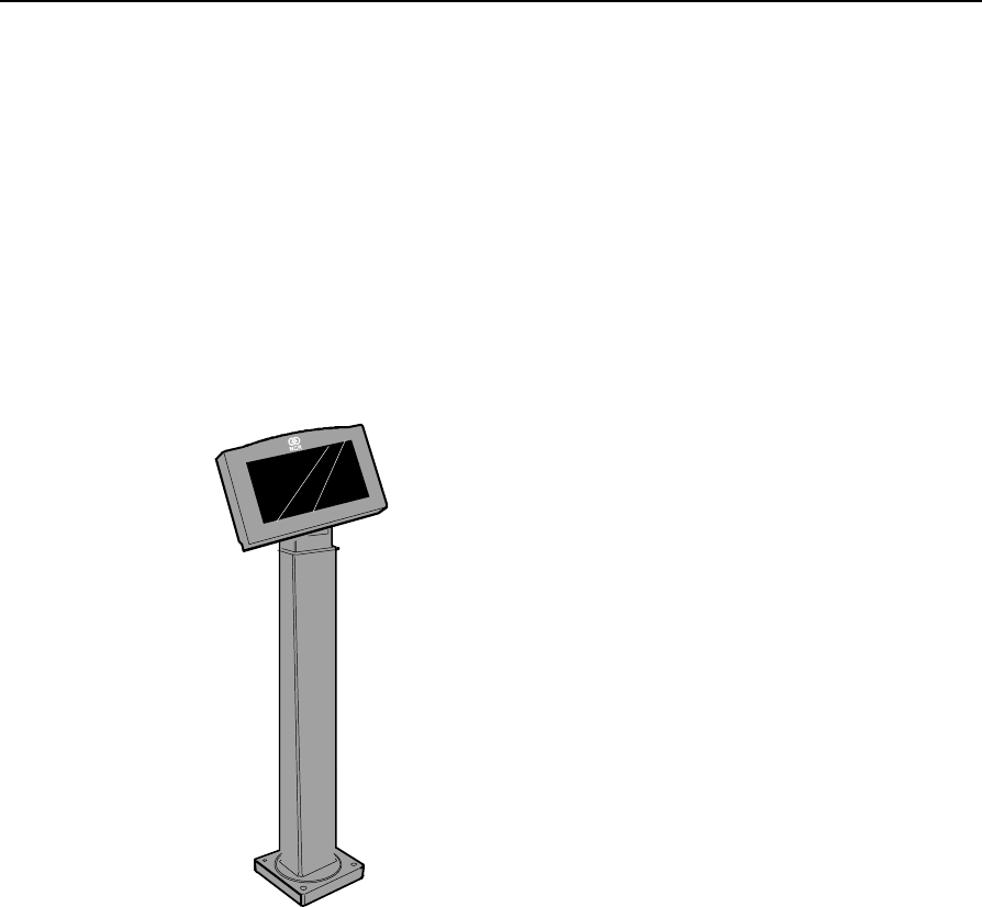
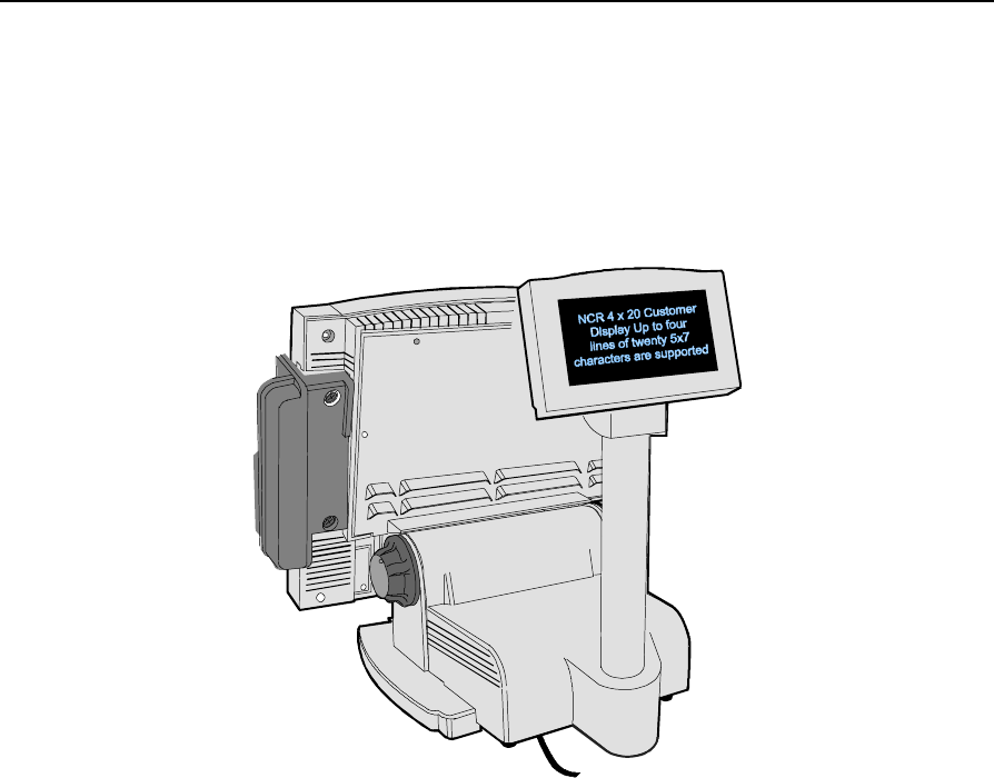
Installing a High-Post Integrated Customer Display
The 7454 Integrated Customer Display supports four lines of twenty
5x7 characters. This is the same display module that is used with the
low-profile integrated display.
16713
Chapter 2: Hardware Installation 2-17
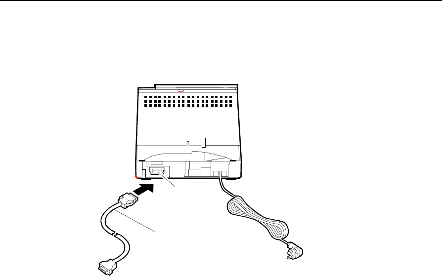
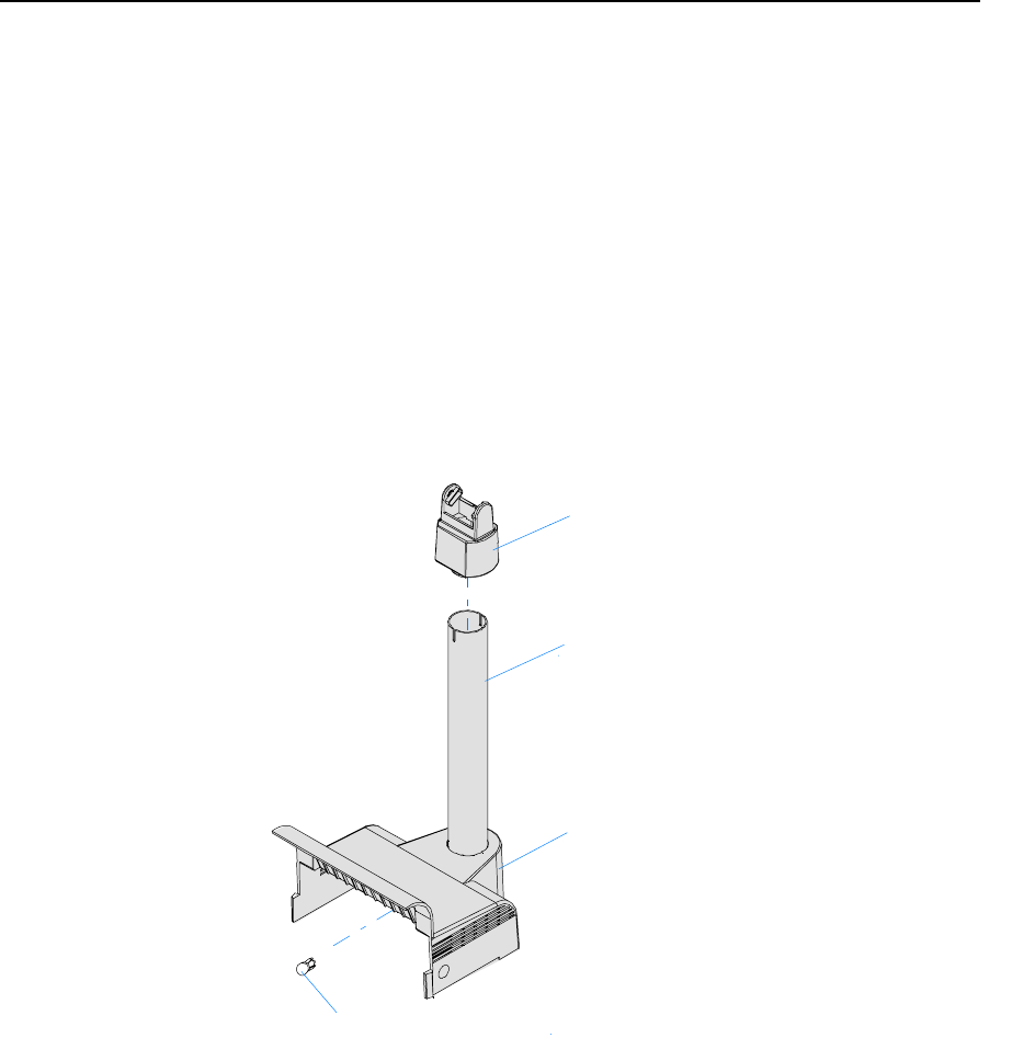
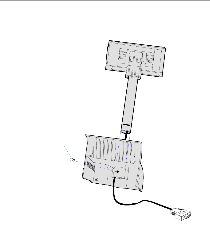
Installing an Integrated Customer Display
(5972-F039)
The standard Power Supply Cover on the 5953-F022 Remote Table Top
Mount does not support attachment of an integrated NCR 7454 4 x 20
Customer Display. In order to mount an integrated display you need to
install 5972-F039, which includes:
1. Power Supply Cover
2. 12-inch Integrated Display Post
3. Top Bracket.
4. Nylon Hole Plug
19726b
3
2
1
4
2-18 Chapter 2: Hardware Installation
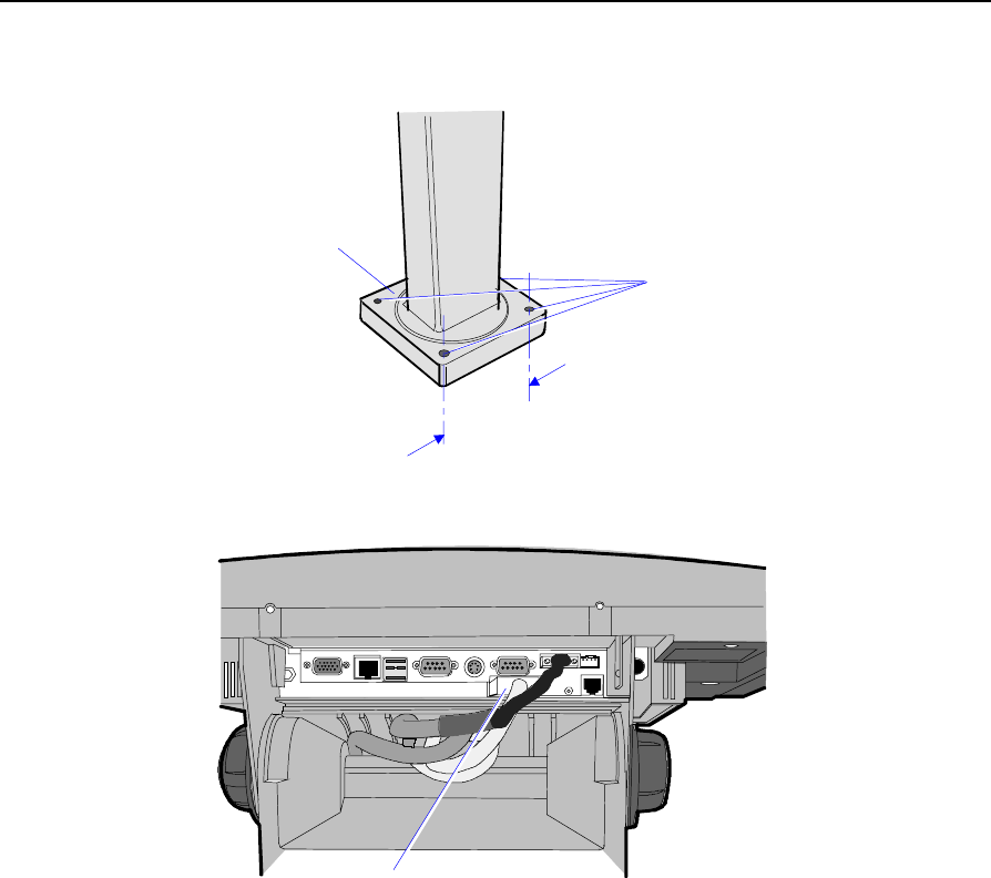
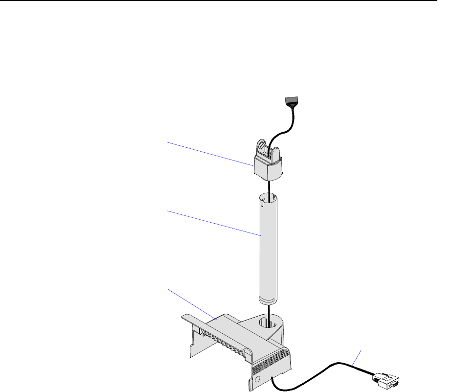
Installation Procedure
1. Route the cable (display connector end) up through the Power
Supply Cover, Display Post, and Top Bracket. This is a tight fit and
the connector has to be angled in order to make it though the
openings. Use care to not damage the wires.
19949a
Top Bracket
Display Post
Power Supply Cover
4 x 20 Integrated
High-Post Cable
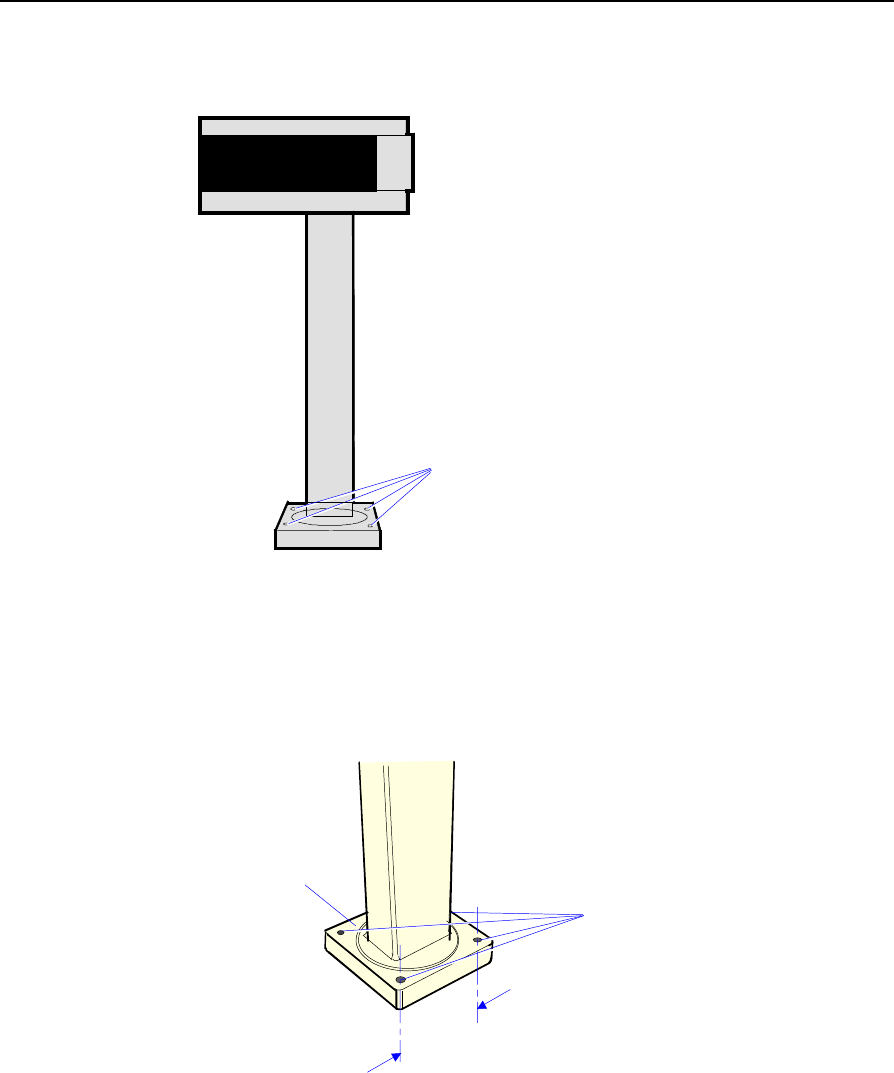
2. Insert the post into the hole on the top of the Power Supply Cover.
Note the orientation above. The slot on the bottom end of the post
should face the inside of the cover.
3. Install the Top Bracket onto the post.
Chapter 2: Hardware Installation 2-19
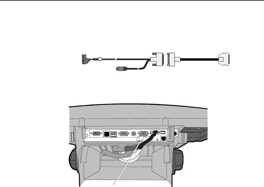
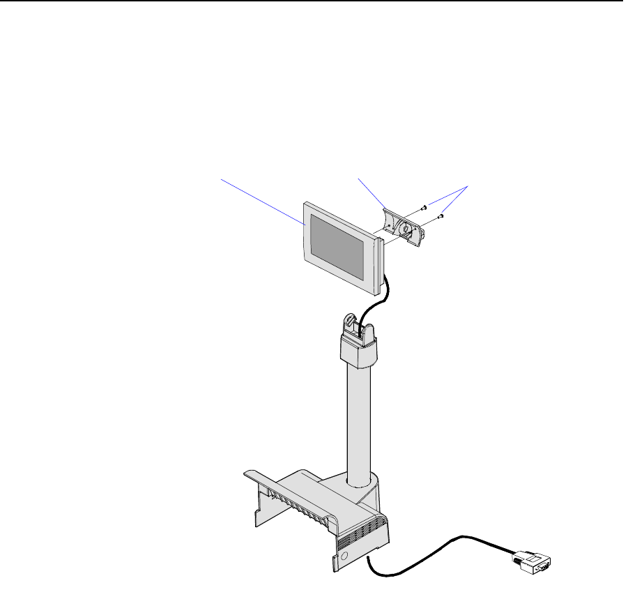
4. Connect the cable to the
a) Remove the Integrated Display Bracket (2 screws).
b) Connect the cable to the 2 x 20 VFD Assembly.
c) Replace the Integrated Display Bracket.
19948a
4 x 20 VFD Assembly Integrated Display Bracket Phillips PH Screw
(4-24 x 0.625)
5. Install the Display Assembly onto the Top Bracket.
2-20 Chapter 2: Hardware Installation
6. Install the Nylon Hole Plug in the Power Supply Cover, locking the
post in place. The slot permits the display to be rotated to personal
preference.
16948
7454 Customer
Display Connector
Nylon Hole Plug
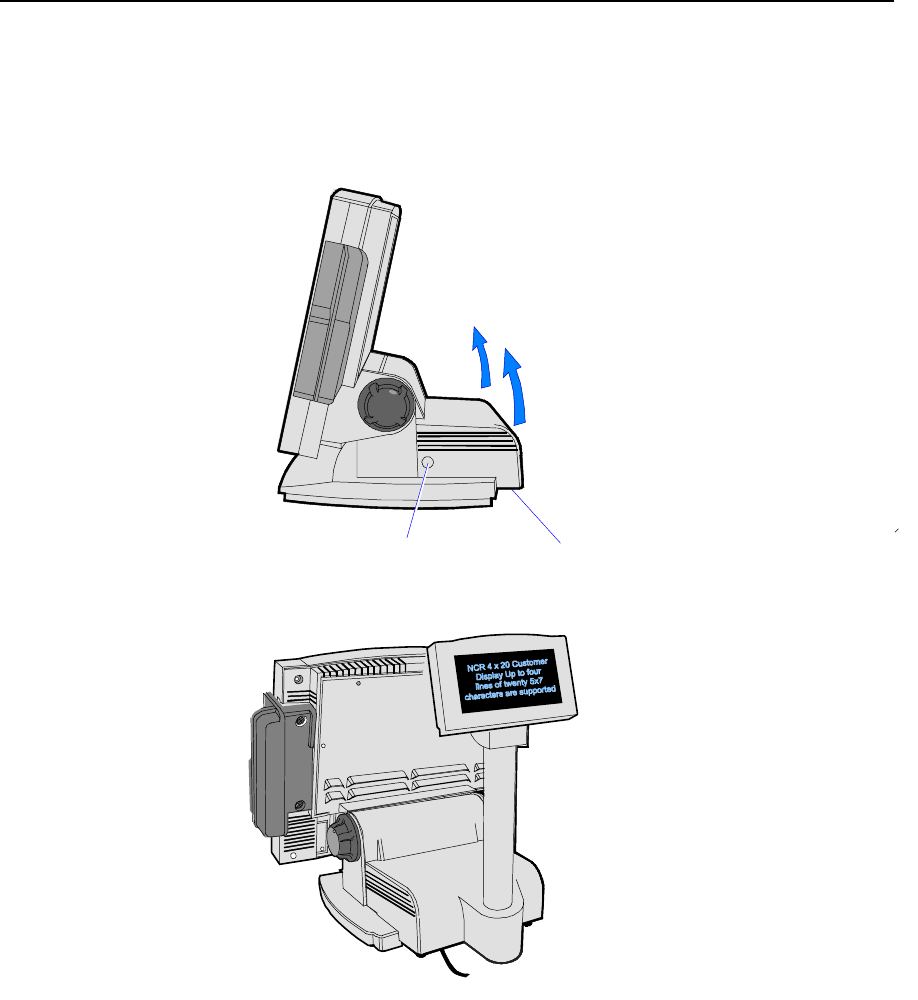
Chapter 2: Hardware Installation 2-21
7. Remove the Power Supply Cover from the 7454 unit.
a) Remove the screws (2) that secure the cover.
b) Press in on both sides of the cover and lift it up in the back to
remove it.
20049
Screws (2)
Press in on Both Sides
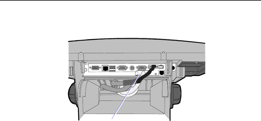
8. Install the Customer Display and Cover assembly onto the 7454
(2 screws).
16713
9. Connect the Display Cable to the Customer Display connector on
the terminal.
2-22 Chapter 2: Hardware Installation
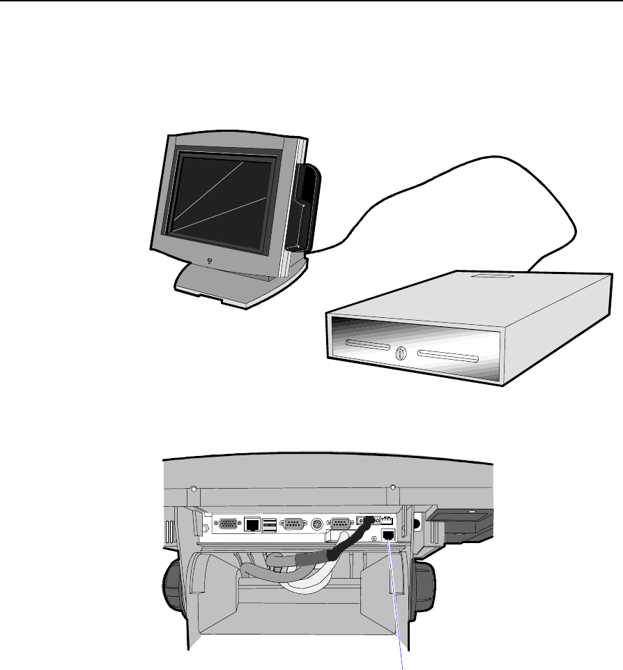
Installing a Cash Drawer
1. Place the cash drawer in the desired location, within cable length of
the terminal.
16269
2. Connect the cash drawer cable to the terminal cash drawer
connector.
15969c
Cash Drawer
Note: The Cash Drawer can optionally be connected to the printer.
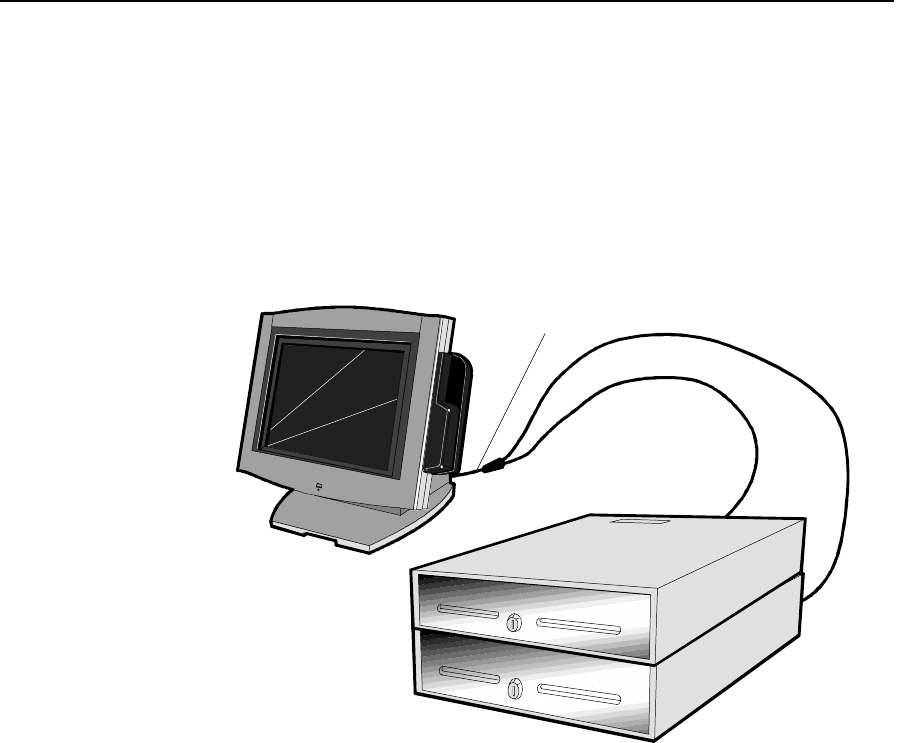
Chapter 2: Hardware Installation 2-23
Installing a Second Cash Drawer
The terminal supports a 2-drawer configuration with a Y-cable
(1416-C372-0006).
1. Place the cash drawer in the desired location, within cable length of
the terminal.
2. Connect the Y-cable to the terminal cash drawer connector.
16270
Dual Cash Drawer Y-Cable
1416-C372-0006
Note: The Y-cable can optionally be connected to the printer.
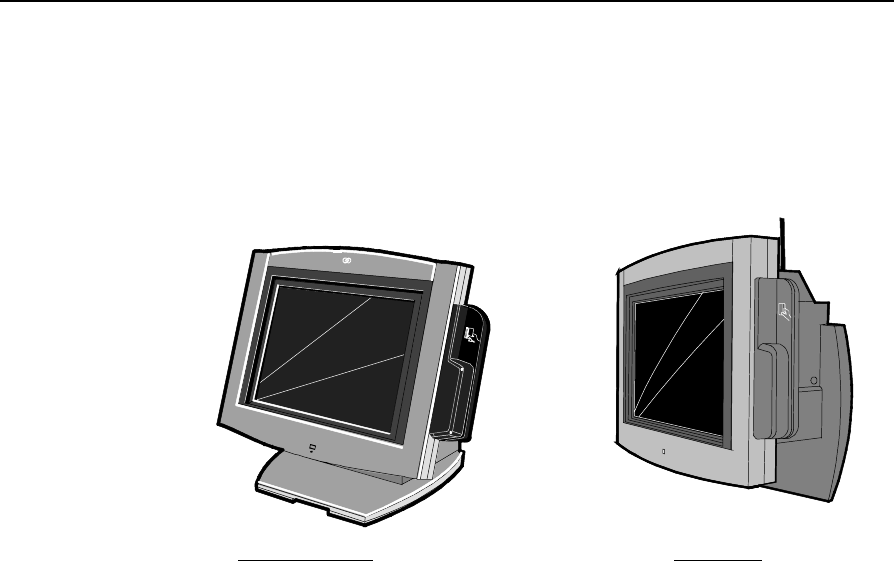
2-24 Chapter 2: Hardware Installation
Mounting the 7454
A Tilt Mount terminal can be installed on a flat horizontal surface or a
flat vertical surface.
16429
NCR
Wall MountTable-Top Mount
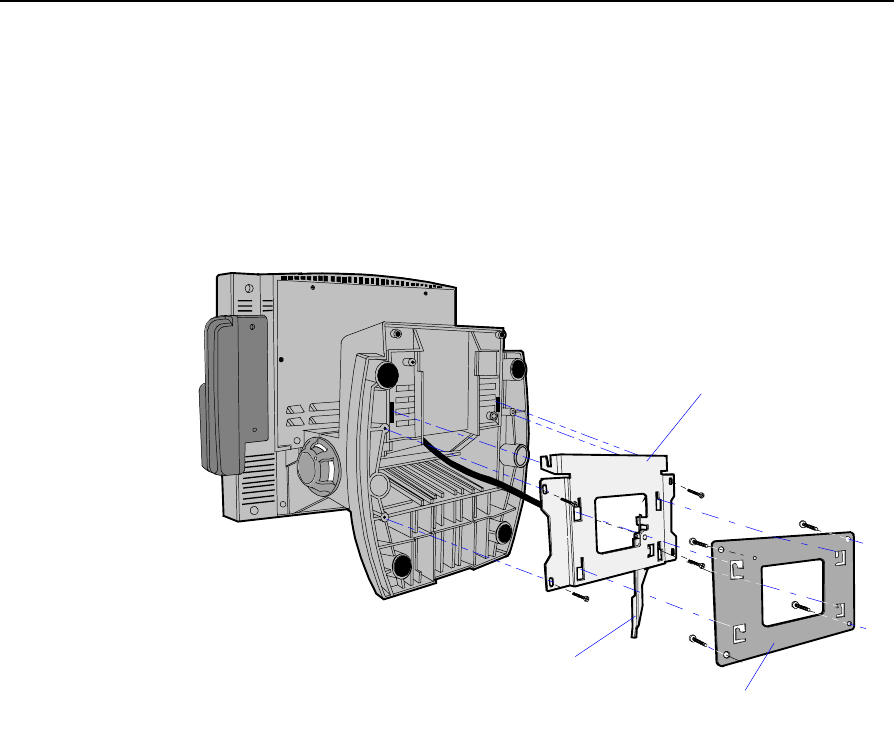
Chapter 2: Hardware Installation 2-25
Wall Mounting a Tilt Mount
To install the Tilt Mount on a flat vertical surface, use the K533 Wall
Mount Bracket Kit.
1. Secure the Wall Plate to the wall with lag screws (4) into the studs
or with hardware of similar strength. The recommended viewing
height for the terminal is 1.2 m (48") from the floor.
16400
Wall Plate
Wall Mount Adapter Plate
Release Lever
2. Install the Wall Mount Adapter Plate to the bottom of the terminal
with screws (4).
3. Install the terminal to the Wall Plate. The bottom of the Wall Mount
Adapter Plate has slots that mate to locking tabs on the Wall Plate.
4. Latch the Release Lever.

2-26 Chapter 2: Hardware Installation
Finalizing the Installation
After the hardware installation has been completed, the terminal can
be powered up to finalize the installation. The operating system, along
with platform modifications, is pre-installed. The following sections list
the steps involved to complete the system installation for each of the
Gold Disk operating systems.
Completing the OS Installation (Win2000)
The system automatically reboots when the image recovery is complete
and starts the software installation. This installation also installs most
of the additional software and drivers that are included in the disk
image. Complete the installation as follows.
1. After the terminal reboots, it will perform a disk check and then
continue with the Windows 2000 installation.
2. Enter the User Name and Organization.
3. Enter the Computer Name for the client.
4. Enter the Administrator’s Account Password (optional)
5. When prompted, press Finish to reboot the client.
6. Login when prompted.
7. Run the MicroTouch screen calibration from the Desktop icon.
Completing the OS Installation (WinXPe)
The system automatically reboots when the image recovery is complete
and starts the software installation. This installation also installs most
of the additional software and drivers that are included in the disk
image. Complete the installation as follows.
1. Click the Admin button to login as Administrator.
2. Read the EULA (End-User License Agreement) information in the
DOS window, then type EXIT and press Enter to close the DOS
window.

Chapter 2: Hardware Installation 2-27
3. Start the Network Setup Wizard.
4. Select options to identify the network information for the terminal
environment.
5. Enter the Computer Description.
6. Enter the Computer Name.
7. Enter the Workgroup Name.
8. When prompted, press Finish to reboot the terminal.
9. Log in when prompted.
1. Open the Control Panel or use the TouchWare Icon on the desktop
and run the MicroTouch screen calibration.
Completing the OS Installation (WinNT)
The system automatically reboots when the image recovery is complete
and starts the software installation. This installation also installs most
of the additional software and drivers that are included in the disk
image. Complete the installation as follows.
1. After the terminal reboots, press Next at the Windows Setup screen.
2. Accept the Microsoft license agreement.
3. Enter the User Name and Organization.
4. Enter the Computer Name for the client.
5. Enter the Administrator’s Account Password (optional).
6. When prompted, press Finish to reboot the client.
7. Log in when prompted.
8. Open the Control Panel and run the MicroTouch screen calibration.
Completing the OS Installation (Win98)
The system automatically reboots when the image recovery is complete
and starts the software installation. This installation also installs most
of the additional software and drivers that are included in the disk
image. Complete the installation as follows.

2-28 Chapter 2: Hardware Installation
1. When the terminal boots it enters the Windows setup routine.
Note: When installing Win98 on terminals with early Processor
Boards (7454-22xx) there are few differences in the procedure as
follows:
a) The terminal starts the Add New Hardware Wizard.
b) For each device found, permit Windows to search for new
drivers (take defaults).
c) After each driver is installed you are asked to reboot. Answer
No.
2. At the User Information screen, enter the User information. This can
be done using a keyboard or you can use the touch screen
keyboard. After entering the information, press Enter or touch OK.
3. Go into the Control Panel and set the terminal Date and Time.
4. In the Control Panel, run the MicroTouch screen calibration.
Completing the OS Installation (Win95)
The system automatically reboots when the image recovery is complete
and starts the software installation. This installation also installs most
of the additional software and drivers that are included in the disk
image. Complete the installation as follows.
1. After the terminal reboots, press Next at the Windows Setup screen.
2. At the User Information screen, enter the User information. This can
be done using a keyboard or you can use the touch screen
keyboard. After entering the information, press Enter or touch OK.
3. Run the MicroTouch screen calibration as described later in this
chapter.
Completing the OS Installation (DOS)
The system automatically reboots when the image recovery is complete
and opens at the DOS C: prompt.
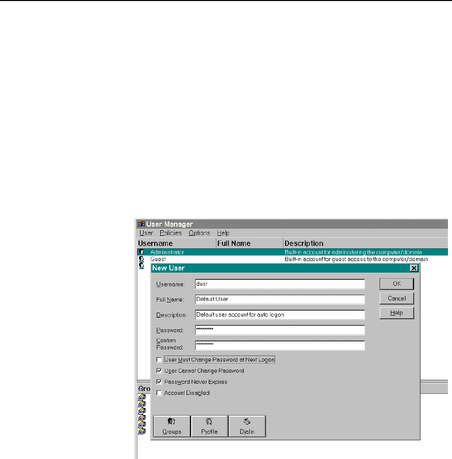
Chapter 2: Hardware Installation 2-29
Setting Auto-Logon (WinNT Terminal)
Since the client does not have a keyboard it is desirous to have it logon
automatically.
1. Create a default user account that you want to use to logon to the
client(s).
a) Open the User Manager. Select the Windows Start button, select
Programs, Administrative Tools (Common), and then Select User
Manager.
b) Select the User menu and then select New User. Give the
account a password (mandatory). As an extra precaution set the
password never expires and that the user can not change it.
c) Select Groups to modify the new user’s group memberships.
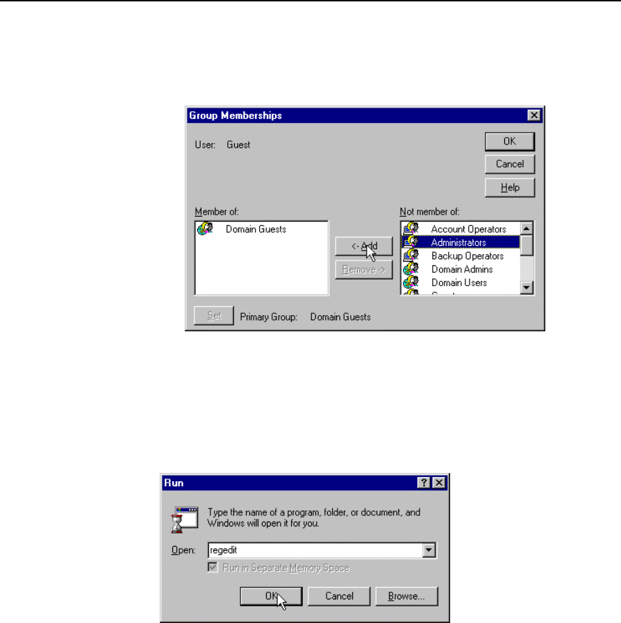
2-30 Chapter 2: Hardware Installation
d) Add the new user to the Administrators group. You need to do
this in order to be able to later turn off the auto-logon
function.
e) Select OK to close the Group Membership box.
f) Select OK to create the account.
2. Modify the Registry. Select the Windows Start button and select
Run.
3. Enter regedit and then select OK.
4. Open the following registry subkey:
HKEY_LOCAL_MACHINE\Software\Microsoft\WindowsNT\
CurrentVersion\Winlogon
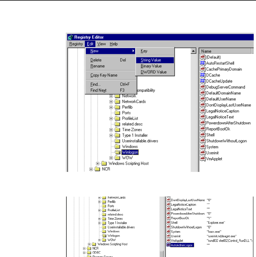
Chapter 2: Hardware Installation 2-31
5. Create a new string value to permit auto logon for the default user.
Select the Edit menu, select New and then select String Value.
6. Name the new entry AutoAdminLogon.
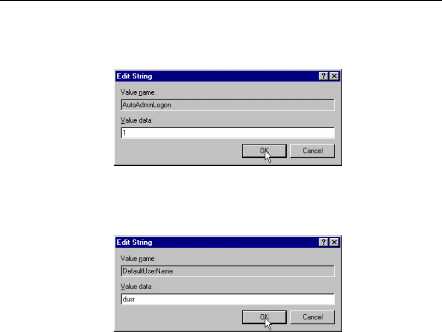
2-32 Chapter 2: Hardware Installation
7. Edit the string value. With the new entry selected, select the Edit
menu and then select Modify. Enter the value 1 for auto-logon. A
value of 0 sets it to no auto-logon.
8. Select OK to set the value.
9. Modify the DefaulUserName to contain the user ID that you want to
automatically logon. With the DefaulUserName selected, select the
Edit menu and then select Modify. Enter the user ID.
10. Select OK to set the value.
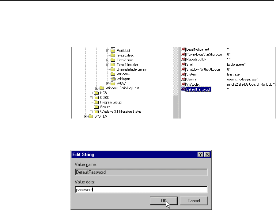
Chapter 2: Hardware Installation 2-33
11. Create a new string value to contain the password for the default
user. Select the Edit menu, select New and then select String Value.
12. Name the new entry DefaultPassword.
13. Edit the string value. With DefaultPassword selected, select the Edit
menu and then select Modify. Enter the value of the password of the
default user (from Step 1). The example below uses password.
14. Select OK to set the value.
This completes the client installation.
To bypass auto logon, and to log on as a different user, hold down the
SHIFT key after a logoff or after a Windows NT restart.

2-34 Chapter 2: Hardware Installation
Installing a Serial Mouse
Follow these steps to install a Serial Mouse on the terminal.
1. Edit the boot.ini file, which is located in the root of the C drive.
a. Open Windows NT Explorer
b. Go to the View menu and select Folder Options.
c. Select the View tab.
d. Scroll down until you see a folder that is labeled Hidden Files.
Make sure the button labeled Show All Files is selected and then
select OK.
e. Select the C drive root directory. Scroll down until you find the
file named boot.ini and select it.
f. Open the File menu and then select Properties.
g. Uncheck the box labeled Read Only and then select OK.
h. Open the boot.ini file with Notepad. It should have the
following entries:
[operating systems]
multi(0)disk(0)rdisk(0)partition(1)\WINNT="Windows
NT Workstation Version 4.00" /NoSerialMice
multi(0)disk(0)rdisk(0)partition(1)\WINNT="Windows
NT Workstation Version 4.00 [VGA mode]" /basevideo
/sos
2. Delete the text /NoSerialMice. The file should now look like:
3. Save the file and then restart the terminal with the serial mouse
connected.
After the terminal restarts it recognizes the mouse and installs the
supporting drivers. The drivers are located on the hard drive at
C:\install\i386. If for some reason they are not on the hard drive,
connect the terminal to a network and share a CD-ROM drive with the
NT Operating System disk installed, or copy the files needed to the
network.

Chapter 2: Hardware Installation 2-35
Guidelines for Calibrating the Touch Screen
The following guidelines should be observed for calibrating the touch
screen.
• Calibration should be done at time of installation
• Recalibrate the touch screen when the system is installed at its final
location.
• Recalibrate whenever the terminal is moved to a new location.
• Recalibrate the touch screen anytime the system has been
disassembled for servicing.
• Only use the Microcal (DOS) program, the Touchware Control
Panel (Windows), or Touchware icon on the Desktop (XPe) to
calibrate the touch screen.
Microcal:
a. Set the video resolution. Go to the Tools menu, Video. Select 800
x 600 256 colors.
b. Go to the Tools menu, select Calibrate.
Touchware Control Panel:
a. Go to the Calibrate tab and press Calibrate.
Calibration Procedure
The calibration program looks at where your finger is when you lift it
off the screen, not where you touch it. Therefore, calibrate the screen as
follows:
1. Touch the screen near the calibration target.
2. Keep your finger on the screen and slide it to the center of the
target.
3. Hold your finger firmly on the target for two seconds, then lift it off
quickly.

2-36 Chapter 2: Hardware Installation
4. Verify that the calibration was set accurately before making a
service call. Perform the calibration again if necessary.
• If cursor is not stable, or false touches are suspected, run the Noise
Check Utility from the Touchware Control Panel (Windows) or
from the Microcal (DOS) program. Choose the recommended
frequency (the one with the lowest noise level). This should also be
done if the touch screen is still not calibrated after one attempt to
recalibrate it.
Microcal:
a. Set the video resolution. Go to the Tools menu, Video. Select
800 x 600 256 colors.
b. Go to the Tools menu, select Noise Check.
c. Follow the instruction prompts. Choose the frequency with the
lowest noise level.
Touchware Control Panel:
a. Go to the Cursor tab and press Stabilize Cursor.
b. Choose the recommended frequency.
• The Edge Adjust should be turned off if using Windows.
Touchware Control Panel:
a. Go to the Cursor tab. Edge Adjustment should be turned off.
Application software can possibly generate a dialog box from the
Touch Driver, with the message that the touch screen needs to be re-
calibrated. If the screen appears to be working normally, then this
message can be ignored. There is a check box labeled, Do not show
this message again. Make sure this box is checked.

Chapter 2: Hardware Installation 2-37
Summary If there is a touch screen calibration issue during or after installation,
take the following actions in the order listed:
1. Recalibrate.
2. If re-calibration is unsuccessful after two attempts, then run the
Noise check to change the frequency.
3. If you are still not able to calibrate, change the touch screen glass.
4. The final step is to replace the Processor Board. If this corrects the
problem, then the old glass is probably OK to reuse.
Out-of-Box Failures
The RSG-Atlanta Customer Satisfaction Hotline will replace out-of-box
failed hard disks with identical, preloaded drives. Once a system is
successfully installed, all disk contents are the responsibility of the
customer. The customer is responsible for restoring operating system
software and/or customer-specific data onto replacement disks sent to
repair a failed or damaged disk in the field. NCR provides recovery
tools for the operating system and platform software.

Chapter 3: Setup
IntroductionThis chapter describes how to configure the BIOS CMOS options.
Following this Introduction, there are sections specific to Pentium
terminals and sections specific to Pentium III/Celeron terminals.
Note: An external alphanumeric keyboard is not required to run the
BIOS CMOS Setup Utility, but a keyboard makes the setup easier.
BIOS Versions The Setup Menus in this chapter reference NCR 7401/7454 BIOS
Version 1.5.0.4 (Pentium) and NCR 7401/7452/7453/7454/7455 BIOS
Version 2.1.2.x (Pentium III).
Entering Setup Without a Keyboard
1. Apply power to the terminal.
2. Calibrate the touch screen.
a) When the screen prompt that says Touch the screen two times to
enter Setup appears, touch the screen three times. This causes
the system to bypass the BIOS Setup and go directly to the
Touch Screen Calibration Setup.
Note: Setup can also be entered from the Boot Menu that is
displayed when you press ESC during POST.
b) As instructed on the screen, touch the circle near the lower-left
corner of the screen. For best results, press the screen near the
circle and then slide your finger onto the circle without raising
your finger from the screen.

3-2 Chapter 3: Setup
c) Using the same method as above, touch the circle near the
upper-right corner of the screen.
You should receive a Successful Calibration message and then the
PhoenixBIOS Setup Utility should come up.
d) Select the setup parameters by touching the controls at the
bottom of the screen.
Entering Setup Using a Keyboard
1. Apply power to the terminal.
2. Press the F2 key when the message at the bottom of the screen
prompts you to do so.
Note: Setup can also be entered from the Boot Menu that is
displayed when you press ESC during POST.
How to Select Menu Options
The following keyboard controls are used to select the various menu
options and to make changes to their values.
• Use the arrow keys to select (highlight) options and menu screens.
• Use the + and - (or F5 and F6) keys to change field values.
• To view help information on the possible selections for the
highlighted item, press F1.
• To save the changes, move the cursor to the Exit Menu, select either
Save Changes & Exit or Save Changes, and press Enter.
Note: If you are not using an external keyboard, you can touch the
menu controls at the bottom of the screen. If you encounter difficulty
doing this, recalibrate the screen.

Chapter 3: Setup 3-3
Restoring Factory Settings
To automatically reset all values to their default settings for the current
screen, press F9. The terminal will automatically load BIOS default
CMOS values for boot up.
To reset all BIOS settings to their default settings go to the Exit menu,
press F9, select either Save Changes & Exit or Save Changes, and press
Enter.
Refer to the BIOS Default CMOS Values section later in this chapter for
the pre-installed Setup defaults.

3-4 Chapter 3: Setup
BIOS Default CMOS Values (Pentium)
The following are the BIOS default CMOS values for the terminal.
Note: When installing a new BIOS from the CD, the Processor Board
type is automatically detected and the correct BIOS is automatically
installed.
Main Values
System Time (variable)
System Date (variable)
Legacy Diskette A: 144 MV/1.25 MV, 3 ½"
Legacy Diskette B: Disabled
IDE Primary Master
Type [Auto]
Cylinders 4191
Heads 16
Sectors/Track 63
Maximum Capacity 2163 MB
Multi-Sector Transfers 16 Sectors
LBA Mode Control Enabled
32 Bit I/O Disabled
Transfer Mode Fast PIO 4
Ultra DMA Mode Disabled
IDE Primary Slave
Type None

Chapter 3: Setup 3-5
IDE Secondary Master
Type None
IDE Secondary Slave
Type None
Memory Cache Enabled
Cache System BIOS area Enabled
Cache Video BIOS area Disabled
System Memory 640 K
Extended Memory 31744 K
Power Savings Disabled
Standby Timeout Off
Auto Suspend Timeout Off
Fixed Disk Disabled
Video Disabled
IDE Drive 0 Monitoring Disabled
IDE Drive 1 Monitoring Disabled
IDE Drive 2 Monitoring Disabled
IDE Drive 3 Monitoring Disabled

3-6 Chapter 3: Setup
PCI Bus Monitoring Disabled
Boot sequence
1. LANDesk® Service
Agent II
2. Hard Drive
Continuous POST Disabled
Advanced Values
I/O Device Configuration
Local Bus IDE adapter Primary
Serial port A Auto
Serial port B Auto
Mode Normal
Parallel port Auto
Mode Bi-directional
Floppy disk controller Disabled
Disk-On-Chip Address Disabled
MSR Address Disabled
Plug and Play No
Reset Configuration Data No
PS/2 Mouse Auto
Large Disk Access Mode DOS

Chapter 3: Setup 3-7
Secured Setup Configurations No
PCI Configuration
ISA Graphics Device Installed No
PCI/PNP ISA UMB Region Exclusion Available (all)

3-8 Chapter 3: Setup
Interrupts (Pentium)
The following table lists the default settings.
IRQ System Resource
NMI I/O Channel Check
0 Reserved, Interval Timer
1 Reserved, Keyboard buffer full
2 Reserved, Cascade interrupt
3 Serial Port 2
4 Serial Port 1
5 User available
6 Reserved, Floppy
7 Parallel Port 1
8Real Time Clock
9 NCR Motion, Thermal interrupt
10 LAN
11 Windows Sound System/USB
12 Touch Screen
13 Reserved, Math coprocessor
14 On-board IDE (available if IDE is disabled)
15 MSR

Chapter 3: Setup 3-9
Memory Map (Pentium)
The following table details the memory map for the Pentium processor.
The ESCD area from ED000-EDFFF is not available for use as an Upper
Memory Block (UMB) by memory managers. The area from E0000-
EBFFF is currently not used by the BIOS and is available for use as
UMB by memory managers. Parts of this area may be used by future
versions of the BIOS to add increased functionality.
Address Range (hex) Size Description
FECFF000-FECFF01B 27 LAN PXE ROM
100000-10000000 255 MB Extended memory
F0000-FFFFF 64 K System BIOS
EE000-EFFFF 8 K Main BIOS (available as UMB)
ED000-EDFFF 4 K ESCD (plug and play configuration
area)
EC000-ECFFF 4 K OEM (available as UMB)
E0000-EBFFF 48 K BIOS Reserved (currently available
as UMB)
D0000-DFFFF 64 K Available HI DOS memory
CE000-CFFFF 8 K Flash Disk (optional)
CC000-CDFFF 8 K NCR Trigantor MSR (optional)
C0000-CBFFF 48 K Onboard video BIOS
A0000-BFFFF 128 K Reserved for video memory
9FC00-9FFFF 1 K Extended BIOS Data (moveable by
QEMM, 386MAX)
80000-9FBFF 127 K Extended conventional
00000-7FFFF 512 K Conventional

3-10 Chapter 3: Setup
BIOS Default CMOS Values (Pentium III/Celeron)
The following are the BIOS default CMOS values for the workstation.
Note: When installing a new BIOS from the CD, the Processor Board
type is automatically detected and the correct BIOS is automatically
installed.
Main Values
Note: An asterisk (*) indicates a variable value based on system
specification, etc. .
System Time *
System Date *
Legacy Diskette A: Disabled
Legacy Diskette B: Disabled
Primary Master 2168 MB
Type Auto
Cylinders 4200
Heads 16
Sectors 63
Maximum Capacity 2168 MB
Total Sectors 4233600
Maximum Capacity 2168MB
Multi-Sector Transfers 16 Sectors
LBA Mode Control Enabled
32 Bit I/O Disabled
Transfer Mode FPI0 4/DMA 2
Ultra DMA Mode Mode 2
Primary Slave None
Type Auto

Chapter 3: Setup 3-11
Multi-Sector Transfers Disabled
LBA Mode Control Disabled
32 Bit I/O Disabled
Transfer Mode Standard
Ultra DMA Mode Disabled
Secondary Master None
Type Auto
Multi-Sector Transfers Disabled
LBA Mode Control Disabled
32 Bit I/O Disabled
Transfer Mode Standard
Ultra DMA Mode Disabled
Secondary Slave None
Type Auto
Multi-Sector Transfers Disabled
LBA Mode Control Disabled
32 Bit I/O Disabled
Transfer Mode Standard
Ultra DMA Mode Disabled
System Memory 640 K
Extended Memory 64512 K
Advanced Values
Installed O/S Other
Secured Setup Configuration No
Reset Confirmation Data No
Cache Memory

3-12 Chapter 3: Setup
Memory Cache Enabled
Cache System BIOS Write Protect
Cache Video BIOS Write Protect
Cache Base 0-512 K Write Back
Cache Base 512K-640 K Write Back
Cache Extended Memory Write Back
Cache A000-AFFF Disabled
Cache B000-BFFF Disabled
Cache C800-CBFF Disabled
Cache CC00-CFFF Disabled
Cache D000-D3FF Disabled
Cache D400-D7FF Disabled
Cache D800-DBFF Disabled
Cache DC00-DFFF Disabled
Cache E000-E3FF Write Protect
Cache E400-E7FF Write Protect
Cache E400-E7FF Write Protect
Cache EC00-EFFF Write Protect
PS/2 Port Touchscreen
USB Port 2 Primary
I/O Device Configuration
Serial Port A Auto
Powered Port Auto
Serial Port B Auto
Parallel Port Auto
Mode ECP
Fdc on Lpt Disabled

Chapter 3: Setup 3-13
Floppy Diskette Controller Enabled
Serial Port C Enabled
Mode Normal
Base I/O Address 3E8
Interrupt IRQ 5
Powered Auto
Serial Port D Enabled
Base I/O Address 2E8
Interrupt IRQ 11
Mode RS-232
Disk-On-Chip Address CE00 - CFFF
MSR Address CC00 - CDFF
MSR Interrupt 6
System Monitors
+12 V Status *
+ 2.5 V Status *
+ 5 V Status *
CPU Temperature *
System Temperature *
Vcc Status *
Vcore Status *
Vio Status *
Vlcd Status *
Vtt Status *
Multiple ROM Menu

3-14 Chapter 3: Setup
On-board Intel LAN Enabled
Parallel CD-ROM Boot Disabled
On-board Intel PXE Enabled
Lucent WaveLAN ROM Disabled
WaveLAN PXE ROM Disabled
Selectable ROM 7 Disabled
Selectable ROM 8 Disabled
Selectable ROM 9 Disabled
Selectable ROM 10 Disabled
Selectable ROM 11 Disabled
Selectable ROM 12 Disabled
Selectable ROM 13 Disabled
Selectable ROM 14 Disabled
Selectable ROM 15 Disabled
Selectable ROM 16 Disabled
Beep Error Codes Off
Large Disk Access Mode DOS
Local Bus IDE Adapter Both
Advanced Chipset Control
Graphics Aperture 64 MB
Enable memory gap Disabled
ECC Config Disabled
SERR Signal condition Multiple bit
Default Primary Video Adapter AGP
PCI/PNP UMB Resource Exclusion
C800 - CBFF Available

Chapter 3: Setup 3-15
CC00 – CFFF Available
D000 – D3FF Available
D400 – D7FF Available
D800 – DBFF Available
DC00 - DFFF Available
PCI/PNP IRQ Resource Exclusion
IRQ 3 Available
IRQ 4 Available
IRQ 5 Available
IRQ 7 Available
IRQ 9 Reserved
IRQ 10 Available
IRQ 11 Available
PCI IRQ line 1: Auto Select
PCI IRQ line 2: Auto Select
PCI IRQ line 3: Auto Select
PCI IRQ line 4: Auto Select
Boot-Time Diagnostic Screen Disabled
QuickBoot Mode Enabled
Continuous POST Disabled
Boot menu retry Keyboard
Allow warm boot Disabled
Security Values
Supervisor Password Is Clear

3-16 Chapter 3: Setup
User Password Is Clear
Set Supervisor Password Press ENTER
Set User Password Press ENTER
Diskette Access Supervisor
Fixed Disk Boot Sector Normal
Password on Boot Disabled
Power Values
Power Savings Disabled
Standby Timeout Off
Auto Suspend Timeout Off
IDE Drive 0 Monitoring Disabled
IDE Drive 1 Monitoring Disabled
IDE Drive 2 Monitoring Disabled
IDE Drive 3 Monitoring Disabled
PCI Bus Monitoring Disabled
Video Power State Control Auto
Boot Values
Intel ( R ) Boot Agent Version 4.0.17
Hard Drive
ATAPI CD-ROM Drive
Removable Devices
Exit Values
Exit Saving Changes Press ENTER

Chapter 3: Setup 3-17
Exit Discarding Changes Press ENTER
Load Setup Defaults Press ENTER
Discard Changes Press ENTER
Save Changes Press ENTER
Interrupts (Pentium III/Celeron)
The following table lists the default settings.
IRQ System Resource
NMI I/O Channel Check
0 Reserved, Interval Timer
1 Reserved, Keyboard buffer full
2 Reserved, Cascade interrupt
3 Serial Port 2
4 Serial Port 1
5 Serial Ports 3 and 4
6 Reserved, Floppy
7 Parallel Port 1
8Real Time Clock
9 NCR Thermal interrupt/PII4 SMBus
10 Audio
11 LAN
12 Mouse (available if disabled)
13 Reserved, Math coprocessor
14 On-board IDE (available if IDE is disabled)
15 On-board IDE (available for MSR if IDE is disabled)

3-18 Chapter 3: Setup

Chapter 3: Setup 3-19
Memory Map (Pentium III/Celeron)
The following table details the memory map for the Pentium III/Celeron
processors. The ESCD area from ED000-EDFFF is not available for use as
an Upper Memory Block (UMB) by memory managers. The area from
E0000-EBFFF is currently not used by the BIOS and is available for use as
UMB by memory managers. Parts of this area may be used by future
versions of the BIOS to add increased functionality.
Address Range (hex) Size Description
FECFF000-FECFF01B 27 LAN PXE ROM
100000-10000000 255 MB Extended memory
F0000-FFFFF 64 K System BIOS
EE000-EFFFF 8 K Main BIOS (available as UMB)
ED000-EDFFF 4 K ESCD (plug and play configuration
area)
EC000-ECFFF 4 K OEM (available as UMB)
E0000-EBFFF 48 K BIOS Reserved (currently available
as UMB)
D0000-DFFFF 64 K Available HI DOS memory
CE000-CFFFF 8 K Flash Disk (optional)
CC000-CDFFF 8 K NCR Trigantor MSR (optional)
C0000-CAFFF 42 K Onboard video BIOS
A0000-BFFFF 128 K Reserved for video memory
9FC00-9FFFF 1 K Extended BIOS Data (moveable by
QEMM, 386MAX)
80000-9FBFF 127 K Extended conventional
00000-7FFFF 512 K Conventional

Chapter 4: Operating System Recovery
Introduction
This chapter discusses procedures how to recover the Operating
System by using the parallel CD-ROM drive. The software is
distributed on bootable CD-ROM media. The drivers that are necessary
to run the CD-ROM are temporarily installed during boot.
It is also possible to perform a BIOS update using a network
connection. Refer to the NCR FitClient Software User's Guide for
information about that procedure.
Prerequisites
The following are required on the 7454 in order to perform an OS
recovery using a CD.
• Bootable CD-ROM drive
• External 2336-K007 (Parallel CD-ROM – Series 5 or Series 6)
• The terminal BIOS must be 1.02.00.00 or greater.
• MicroSolutions BackPack CD-ROM Series 6 requires BIOS
2.1.1.1 or greater
• Keyboard
Caution: When performing an OS recovery from a larger source
image (larger disk) to a smaller destination disk you must use the
special procedure described in the OS Recovery from a Larger Disk Image
section that follows.
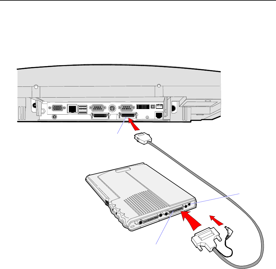
4-2 Chapter 4: Operating System Recovery
Updating Procedures
1. Connect the external CD-ROM (2336-K007) drive to the parallel
port on the terminal.
2. Connect the power connector to the CD-ROM drive.
18250
Parallel Connector
Parallel Connector
Power
Connector
Note: The parallel port on the 7454 is the Customer Display port.
Therefore, if your terminal is configured with a Customer Display,
you must temporarily disconnect it in order to use the CD-ROM
drive.

Chapter 4: Operating System Recovery 4-3
3. Apply power to the terminal so the CD-ROM drive can be opened.
4. Insert the CD that contains the operating system image.
7454
Model Software CD LPINs
Win2000 WinXPe WinNT Win98 Win95 DOS
*22xx D370-0489-0100 Not Supported D370-0433-0100 D370-0444-0100 D370-0442-0100 D370-0445-0100
32xx D370-0516-0100 D370-0565-0100 D370-0501-0100 D370-0500-0100 D370-0503-0100
**Controlled D370-0445-0100
34xx,
35xx,
36xx,
37xx
D370-0516-0100 D370-0565-0100 D370-0501-0100 D370-0500-0100 **Discontinued D370-0445-0100
Note: * The 22xx models have been discontinued. Contact NCR
Product Manager for LPIN availability.
** Contact Product Manager for Controlled Delivery support of
Windows 95 LPIN for 32xx model.
5. Boot the terminal.
6. Press F2 at the screen prompt to enter Setup.
7. Press F9 to set BIOS System defaults.
8. In the Advanced menu, select I/O Device Configuration.
9. Verify that the LPT 1 Mode is set to ECP.
10. Go back to the Advanced menu, select Multiple ROM Menu.
11. Set the Parallel CD-ROM Boot to Enabled.
12. Set all other Boot options to Disabled.
13. Exit Setup and Save Changes.
As the terminal reboots, you should see a message during boot
indicating that the CD-ROM has been recognized:
Micro Solutions BACKPACK CD-ROM v0.3
. . .
Booting from BACKPACK CD
Starting MS-DOS

4-4 Chapter 4: Operating System Recovery
14. Follow the DOS screen prompts. After each entry you are asked to
confirm your input. You can use 1 or y for Yes, 2 or n for No.
15. Enter whether or not you want to perform Disk verification.
(Answering Yes takes twice as long, but is recommended.)
If Yes is selected:
• The Ghost® software verifies write operations and handles bad
FAT clusters.
• The Ghost error file (GHOST.ERR) is displayed before
rebooting
If No is selected:
• The Ghost error file is displayed before rebooting only if Ghost
aborts.
Caution: If the error file is displayed, the batch file pauses for
user input before rebooting. You may use Ctrl-C to cancel out of
the batch file if you want to see the error file again, but nothing
should be done that writes to the hard disk before rebooting.
GHOST.ERR is on the RAM disk and is lost on reboot.
16. Select which type of recovery you want to perform from the next
menu (normally option #1).
1) Redo entire disk with the first partition the same size.
2) Redo the first OS partition.
3) Redo the second OS partition.
The Ghost software then begins the disk recovery from the CD. It
displays a progress bar and gives you an estimate how long the
process should take.
When the recovery process is completed, the client hard disk is
restored to its preinstalled condition, as originally received from
the factory.
17. At the completion of the recovery process remove the CD and press
ENTER to reboot the terminal.

Chapter 4: Operating System Recovery 4-5
18. Remove the CD during reboot for the OS to begin. When system is
restored, reset the BIOS to normal defaults.
Completing the OS Installation (Win2000)
The system automatically reboots when the image recovery is complete
and starts the software installation. This installation also installs most
of the additional software and drivers that are included in the disk
image. Complete the installation as follows.
1. After the terminal reboots, it will perform a disk check and then
continue with the Windows 2000 installation.
2. Enter the User Name and Organization.
3. Enter the Computer Name for the client.
4. Enter the Administrator’s Account Password (optional)
5. When prompted, press Finish to reboot the client.
6. Login when prompted.
7. Run the MicroTouch screen calibration from the Desktop icon.
Completing the OS Installation (WinXPe)
The system automatically reboots when the image recovery is complete
and starts the software installation. This installation also installs most
of the additional software and drivers that are included in the disk
image. Complete the installation as follows.
1. Click the Admin button to login as Administrator.
2. Read the EULA (End-User License Agreement) information in the
DOS window, then type EXIT and press Enter to close the DOS
window.
3. Start the Network Setup Wizard.
4. Select options to identify the network information for the terminal
environment.
5. Enter the Computer Description.
6. Enter the Computer Name.

4-6 Chapter 4: Operating System Recovery
7. Enter the Workgroup Name.
8. When prompted, press Finish to reboot the terminal.
9. Log in when prompted.
10. Open the Control Panel or use the TouchWare Icon on the desktop
and run the MicroTouch screen calibration.
Completing the OS Installation (WinNT)
The system automatically reboots when the image recovery is complete
and starts the software installation. This installation also installs most
of the additional software and drivers that are included in the disk
image. Complete the installation as follows.
1. After the terminal reboots, press Next at the Windows Setup screen.
2. Accept the Microsoft license agreement.
3. Enter the User Name and Organization.
4. Enter the Computer Name for the client.
5. Enter the Administrator’s Account Password (optional).
6. When prompted, press Finish to reboot the client.
7. Log in when prompted.
8. Open the Control Panel and run the MicroTouch screen calibration.
Completing the OS Installation (Win98)
The system automatically reboots when the image recovery is complete
and starts the software installation. This installation also installs most
of the additional software and drivers that are included in the disk
image. Complete the installation as follows.
1. When the terminal boots it enters the Windows setup routine.
Note: When installing Win98 on terminals with early Processor
Boards (7454-22xx) there are few differences in the procedure as
follows:
a) The terminal starts the Add New Hardware Wizard.

Chapter 4: Operating System Recovery 4-7
b) For each device found, permit Windows to search for new
drivers (take defaults).
c) After each driver is installed you are asked to reboot. Answer
No.
2. At the User Information screen, enter the User information. This
can be done using a keyboard or you can use the touch screen
keyboard. After entering the information, press Enter or touch OK.
3. Go into the Control Panel and set the terminal Date and Time.
4. In the Control Panel, run the MicroTouch screen calibration.
Completing the OS Installation (Win95)
The system automatically reboots when the image recovery is complete
and starts the software installation. This installation also installs most
of the additional software and drivers that are included in the disk
image. Complete the installation as follows.
1. After the terminal reboots, press Next at the Windows Setup screen.
2. At the User Information screen, enter the User information. This
can be done using a keyboard or you can use the touch screen
keyboard. After entering the information, press Enter or touch OK.
3. Open the Control Panel and run the MicroTouch screen calibration.
Completing the OS Installation (DOS)
The system automatically reboots when the image recovery is complete
and opens at the DOS C: prompt.

4-8 Chapter 4: Operating System Recovery
Gold Disk Contents
This section describes the contents of each of the Gold Disk Images,
including all the additions and changes that were made on top of the
generic operating system.
Important: For each operating system, NCR strongly recommends
that the drivers placed in the c:\install directory be left there for
the purposes of servicing and maintaining the system. If you are using
the information in this section to build your own operating system
image and not using NCR’s provided OS Recovery image as a base
image, then we recommend that all installed drivers be placed in a
similar c:\install directory for support.
Microsoft Operating System License Agreements
When purchasing a workstation or kiosk preloaded with a Microsoft
operating system, the application provider must follow certain license
agreement guidelines. Listed below are some of the major points of
Microsoft’s “Embedded Software” agreement, which currently covers
DOS, Win 3.11, Windows 95, Windows 98, Windows NT, Windows
2000, and Windows XPe.
• The end user application should not permit the user (typically a
cashier) to exit the application so that they may be able to browse
the operating system desktop, explorer, or other Microsoft
operating system user interface elements. This does not apply to
servicing, upgrading, or diagnosing problems for the workstation
by services or field engineers. This restriction is meant to ensure
that the end user is only permitted to navigate within the confines
of the end user’s application under normal operating conditions.
• The NCR OS Recovery image can only be used to recover or update
systems with licenses procured from NCR.

Chapter 4: Operating System Recovery 4-9
Operating System Restrictions
The following section describes restrictions for operating systems used
with the 7454 terminal.
Standby and Hibernate Mode Restriction
When using a 7454 terminal without a keyboard or mouse, the
Windows 2000, Windows XP PRO, and Windows XP Embedded OS
Standby Mode and Hibernate Mode should be avoided. These two modes
place the hardware in a low power state which requires an interrupt to
restart the processor.
The Windows 2000 and Windows XP Embedded Gold Disk Images
disable Hibernate Mode and Standby Mode on the 7454 terminal. These
two modes should not be used without a keyboard or mouse.

4-10 Chapter 4: Operating System Recovery
NCR 7454-32xx Win2000 Operating System Recovery Software
(Version 02.02.00.02)
(LPIN: D370-0516-0100)
Note: This product should only be used on 7454 terminals with a
Microsoft Windows 2000 license
7454-32xx Windows 2000 Operating System Recovery Software
provides the means of restoring the operating system to the hard disk
of a 7454 POS terminal. The bootstrap program (di_intel.bsd) and disk
recovery boot image (di_intel.bid) are downloaded to the target
terminal over the network and restore the hard disk to the preinstalled
state as shipped from the factory. This enables installation of the
following software:
• Microsoft Windows 2000 Professional w/ SP2
• Microsoft Internet Explorer 6.0 (6.0.2600.0000)
• Internet Explorer SP1
• SMI Lynx EM/EM+ Video driver (5.0.2195.178)
• SoundFusion Audio driver (5.12.01.3041)
• Intel 82559 Ethernet LAN drivers (5.0.67.0)
• NCRSYSM driver (3.0.1.9)
• Windows Installer (2.0)
• MicroTouch drivers (5.63)
The following drivers are not installed automatically, but can be
installed from their respective locations (Readme files exist in these
locations, as well):
• Backpack CD-ROM (3.02) C:\Install\Drivers\CDRom
• Edgeport USB (1.16.9) C:\Install\Drivers\USB

Chapter 4: Operating System Recovery 4-11
Furthermore, the following settings/revisions have been configured:
• Preinstalled W2K to include the Product ID Number (PID)
• Placed the Gold Drive Part Number, Date Created, LPIN, and
Release in Registry under:
HKey-Local_Machine\Software\NCR\Gold Drive
• Ran Sysprep, using sysprep.inf and sysprep.bat, so that the mini
installation will run on initial boot with the following parameters:
- Automatically include PID
• Established a FAT32 primary system partition that fills the entire
drive
• Included necessary OS cab files in C:\Install
• Installed SP2
• Exposed to both EM and EM+ video chipsets
• Exposed to a mouse so MicroTouch will install properly
• Installed SMI Control Panel (4.3.5)
• Installed Intel Proset utility
• Set virtual memory to 192-394
• Enabled APM
• Set ‘APM monitor shutoff’ to ‘Never’
• ‘Enable PME’ (in Intel Proset utility) set to ‘Hardware Default’
• Disabled game port
• Enabled DMA
• Set color to 16 bit
• Added SetResolution.exe to RunOnce registry.
• Added TerminalCheck.exe to Run registry.
• Added NCR-specific EULA.
• Added '/noguiboot' parameter to boot.ini to hide splash at startup.

4-12 Chapter 4: Operating System Recovery
NCR 7454-3xxx WinXPe Operating System Recovery Software
(Version 02.02.00.01)
(LPIN: D370-0565-0100)
Note: This product should only be used on 7454 terminals with a
Microsoft Windows XPe license.
7454-3xxx Windows XPe Operating System Recovery Software
provides the means of restoring the operating system to the hard disk
of a 7454 POS terminal. The bootstrap program (di_intel.bsd) and disk
recovery boot image (di_intel.bid) are downloaded to the target
terminal over the network and restore the hard disk to the preinstalled
state as shipped from the factory. This enables installation of the
following software:
• Microsoft Windows XPe w/ SP1
• SMI Lynx EM/EM+ Video driver (6.13.10.228)
• Intel 82559 Ethernet LAN drivers (6.01.03.0000)
• NCRSYSM driver (3.0.4.12)
• MicroTouch drivers (5.64)
The following drivers are not installed automatically, but can be
installed from their respective locations (Readme files exist in these
locations, as well):
• Backpack CD-ROM (4.0.100.1190) C:\Install\Drivers\CDRom
• Edgeport USB (2.20) C:\Install\Drivers\USB
• Inside Out Networks
Watchport/V Camera (2.20) C:\Install\Drivers\Camera

Chapter 4: Operating System Recovery 4-13
Furthermore, the following settings/revisions have been configured:
• Preinstalled XPe to include the Product ID Number (PID)
• Placed the Gold Drive Part Number, Date Created, LPIN, and
Release in Registry under:
HKey-Local_Machine\Software\NCR\Gold Drive
• Established a NFTS primary system partition that fills the entire
drive
• Included necessary OS cab files in C:\Install
• Installed SMI Control Panel (4.2.2)
• Installed Intel Proset utility
• Set virtual memory to 128
• Enabled APM
• Set ‘APM monitor shutoff’ to ‘Never’
• Set ‘Enable PME’ (in Intel Proset utility) to ‘Hardware Default’
• Set color to 24 bit
• Added SetResolution.exe to RunOnce registry.
• Added NCR-specific EULA.
NCR 7454-22xx Win2000 Operating System Recovery Software
(Version 01.01.00.00
(LPIN: D370-0489-0100)
Installs the following software:
• Microsoft Windows 2000 Professional with Service Pack 1
• Microsoft Internet Explorer 5.0 (5.00.3103.1000)
• Chips and Technologies 69000 Assailant Video driver (2.46 Beta)
• Crystal Audio Codec driver (5.0.2184.1)
• Intel(R) 82559 Fast Ethernet LAN driver (5.0.67.0)

4-14 Chapter 4: Operating System Recovery
• MicroTouch Touchware (5.6C2)
• Backpack CD-Rom drivers available (version 3.02)
Configures the following settings/revisions:
• Sysprep.inf answer file and sysprep.bat batch file created to:
− Skip EULA
− Preinstall the Product ID Number (PID)
• Placed the Gold Drive Part Number, Date Created, LPIN, and
Release in Registry under:
HKey-Local_Machine\Software\NCR\Gold Drive
• Windows Installer (Version 1.1) installed

Chapter 4: Operating System Recovery 4-15
NCR 7454-32xx NT Operating System Recovery Software
(Version 02.02.00.01
(LPIN: D370-0501-0100)
Note: This product should only be used on 7454 terminals with a
Microsoft Windows NT license.
7454-32xx NT Operating System Recovery Software provides the
means of restoring the operating system to the hard disk of a 7454 POS
terminal. The bootstrap program (di_intel.bsd) and disk recovery boot
image (di_intel.bid) are downloaded to the target terminal over the
network and restore the hard disk to the preinstalled state as shipped
from the factory. This permits installation of the following software:
• Microsoft Windows NT with SP6a
• Microsoft Internet Explorer 6.0 (6.0.2600.0000)
• Internet Security Update (Q323759.exe)
• SMI Lynx 3DM Video driver (4.00.1381.0178)
• SoundFusion Audio driver (4.01.2086)
• Intel 82559 Ethernet LAN drivers (5.00.66.0000)
• NCRSYSM driver (3.0.1.9)
• Windows Installer (2.0)
• MicroTouch drivers (5.63 SR3)
The following drivers are not installed automatically, but can be
installed from their respective locations (Readme files exist in these
locations, as well):
• Backpack CD-ROM (2.04) C:\Install\Drivers\CDRom
• Edgeport USB (2.13) C:\Install\Drivers\USB

4-16 Chapter 4: Operating System Recovery
Furthermore, the following settings/revisions have been configured:
• Preinstalled NT to include the Product ID Number (PID)
• Placed the Gold Drive Part Number, Date Created, LPIN, and
Release in Registry under:
HKey-Local_Machine\Software\NCR\Gold Drive
• Ran Sysprep (so that the mini installation will run on initial boot)
with the following parameters:
- Automatically include PID
• Host.cmd set in RunOnce to update the registry
• Established a 2gb FAT16 primary system partition
• Established a secondary NTFS partition that fills the remainder of
the drive
• Included necessary OS cab files in C:\Install
• Made SP6a folder available in C:\Install (installed)
• Exposed to both EM and EM+ video chipsets
• Installed SMI Control Panel (4.3.5)
• Installed Intel Proset utility
• 'Enable PME' (in Intel Proset utility) set to 'Hardware Default'
• Enabled DMA
• Muted Volume Line-In
• Added SetResolution.exe to RunOnce registry.
• Added TerminalCheck.exe to Run registry.
• Added NCR-specific EULA.
• Added '/noguiboot' parameter to boot.ini to hide splash at startup.

Chapter 4: Operating System Recovery 4-17
NCR 7454-22xx NT Operating System Recovery Software
(Version 01.04.01.00
(LPIN: D370-0433-0100)
Installs the following software:
• Microsoft Windows NT Workstation 4.0 with Service Pack 4a.
Service Pack 6 included (but not installed) on the disk
• Microsoft Internet Explorer 5.0
• MicroTouch TouchWare Version 5.4 for Mouse Port software
• Chips & Technologies 69000 Video driver
• CrystalWare Audio driver
• Intel EtherExpress software
• Intel PIIX Bus Master IDE drivers
• M-Systems DiskOnChip 2000 driver (not installed) available
• Backpack CD-ROM drivers (not installed) available
Configures the following settings/revisions:
• Enables the NT Dump settings to:
− send an administrative alert
− write dump to file
− overwrite existing file
− auto reboot after dump
• Mutes the Volume Line-In
• Changes event log to overwrite events as needed for the
Application Type event logs
• Changes the Windows Scroll Bar Size from 16 to 18 pixels for easier
Touch response

4-18 Chapter 4: Operating System Recovery
• Sysprep.inf answer file created to:
− Skip EULA
− Preinstall the Product ID Number (PID)
• Places the Gold Drive Part Number, Date Created, LPIN, and
Version in Registry under:
HKey-Local_Machine\Software\NCR\Gold Drive
• Windows Installer (Version 1.1) installed
• Removes the following key from the registry (as a current COM9
issue workaround):
Hkey_Local_Machine\System\CurrentControlSet\Servi
ces\Serial\Parameters\ Serial 10999
• Changes page file size to 139-256

Chapter 4: Operating System Recovery 4-19
NCR 7454-32xx Win98 Operating System Recovery Software
(Version 02.02.00.01)
(LPIN: D370-0500-0100)
Note: This product should only be used on 7454 terminals with a
Microsoft Windows 98 license.
7454-32xx Win98 Operating System Recovery Software provides the
means of restoring the operating system to the hard disk of a 7454 POS
terminal. The bootstrap program (di_intel.bsd) and disk recovery boot
image (di_intel.bid) are downloaded to the target terminal over the
network and restore the hard disk to the preinstalled state as shipped
from the factory. This permits installation of the following software:
• Microsoft Windows 98SE
• Microsoft Internet Explorer 6.0 (6.0.2600.0000)
• Internet Explorer Security Update (Q323759.exe)
• SMI Lynx 3DM Video driver(4.12.01.0034)
• SoundFusion Audio driver (4.12.2885)
• Intel 82559 Ethernet LAN drivers (5.00.67.0000)
• NCRSYSM driver (3.0.1.8)
• Windows Installer (2.0)
• MicroTouch drivers (5.63 SR3)
The following drivers are not installed automatically, but can be
installed from their respective locations (Readme files exist in these
locations, as well):
• Backpack CD-ROM (2.04) C:\Install\Drivers\CDRom
• Edgeport USB (1.16.9) C:\Install\Drivers\USB

4-20 Chapter 4: Operating System Recovery
Furthermore, the following settings/revisions have been configured:
• Preinstalled Win98 to include the Product ID Number (PID)
• Placed the Gold Drive Part Number, Date Created, LPIN, and
Release in Registry under:
HKey-Local_Machine\Software\NCR\Gold Drive
• Added Userinfo.exe to Start Menu to capture User Name, User
Organization, Computer Name, and Workgroup (once the user has
entered this information, userinfo will remove itself from the Start
Menu)
• Established a FAT32 primary system partition that fills the entire
drive
• Included necessary OS cab files in C:\Install
• Exposed to both EM and EM+ video chipsets
• Installed Intel Proset Utility
• Applied a Microsoft hotfix to replace usbhub.sys version 4.10.2222
with 4.10.2223; this executable has been placed in
C:\Install\Drivers\USB\Hotfix
• Enabled DMA
• Disabled DSound Acceleration and Sensaura/EAX in the
SoundFusion control panel
• Disabled game device and joystick
• Set to High Color
• ‘Enable PME’ (in Intel Proset utility) set to ‘Hardware Default’
• Muted the Volume Line-In
• Added SetResolution.exe to RunOnce registry.
• Added TerminalCheck.exe to Run registry.
• Added NCR-specific EULA.
• Added '/noguiboot' parameter to boot.ini to hide splash at startup.

Chapter 4: Operating System Recovery 4-21
NCR 7454-22xx Win98 Operating System Recovery Software
(Version 01.01.00.00)
(LPIN: D370-0444-0100)
Installs the following software:
• Microsoft Windows 98 Second Edition
• Microsoft Internet Explorer 5.0
• MicroTouch TouchWare Version 5.4 for Mouse Port software
• Chips & Technologies 69000 Video driver
• Crystal Audio driver
• Intel 8255x-based PCI Ethernet Adapter
• Intel PIIX Bus Master IDE drivers
• Backpack CD-ROM drivers (not installed) available
Configures the following settings/revisions:
• Mutes the Volume Line-In
• Places the Gold Drive Part Number, Date Created, LPIN, and
Version in Registry under:
HKey-Local_Machine\Software\NCR\Gold Drive
• Windows Installer (Version 1.1) installed

4-22 Chapter 4: Operating System Recovery
NCR 7454-32xx Win95 Operating System Recovery Software
(Version 02.01.00.01)
(LPIN: D370-0503-0000)
Note: This product should only be used on 7454 terminals with a
Microsoft Windows 95 license.
7454-32xx Windows 95 Operating System Recovery Software provides
the means of restoring the operating system to the hard disk of a 7454
POS terminal. The bootstrap program (di_intel.bsd) and disk recovery
boot image (di_intel.bid) are downloaded to the target terminal over
the network and restore the hard disk to the preinstalled state as
shipped from the factory. This permits installation of the following
software:
• Microsoft Windows 95 OSR2
• Microsoft Internet Explorer 5.5 (5.50.4134.0600)
• SMI Lynx 3DM Video driver (4.12.01.0034)
• SoundFusion Audio driver (4.12.2885)
• Intel 82559 Ethernet LAN drivers (5.00.66.0000)
• PIIX IDE BusMaster drivers (3.3.0.2)
• NCRSYSM driver (2.01.01.004)
• Windows Installer (1.1)
• MicroTouch drivers (5.62)
The following drivers are not installed automatically, but can be
installed from their respective locations (Readme files exist in these
locations, as well):
• Backpack CD-ROM (2.04) C:\Install\Drivers\CDRom
• M-Systems DiskOnChip (4.2) C:\Install\Drivers\DskonChp
• Edgeport USB (1.15.2) C:\Install\Drivers\USB

Chapter 4: Operating System Recovery 4-23
Furthermore, the following settings/revisions have been configured:
• Preinstalled Win95 to include the Product ID Number (PID)
• Placed the Gold Drive Part Number, Date Created, LPIN, and
Release in Registry under:
HKey-Local_Machine\Software\NCR\Gold Drive
• Added Userinfo.exe to Start Menu to capture User Name, User
Organization, Computer Name, and Workgroup (once the user has
entered this information, userinfo will remove itself from the Start
Menu)
• Established a 2gb FAT16 primary system partition
• Established a secondary FAT32 partition that fills the remainder of
the drive
• Included necessary OS cab files in C:\Install
• Exposed to both EM and EM+ video chipsets
• Installed Intel Proset Utility
• Disabled game device and joystick
• Set color to 256

4-24 Chapter 4: Operating System Recovery
NCR 7454-22xx Win95 Operating System Recovery Software
(Version 01.02.00.00)
(LPIN: D370-0442-0000)
Installs the following software:
• Win95 w/PID
• Msdos.sys file edited to include the following parameter:
Autoscan = 2
• IE5
• MicroTouch version 5.4
• Volume Line-in set to 0
• Scroll Bar Size set to 18
• PCMCIA files updated:
− Cbss.vxd
− Pci.vxd
− Pccard.vxd
− Pcmcia.inf
• Userinfo.exe added (User info input)
• Windows Installer
• Amdk6upd.exe
• Version control added to Registry to track Gold Disk version info:
Hkey_Local_Machine\Software\NCR\FitSock\Gold Drive

Chapter 4: Operating System Recovery 4-25
OS Recovery from a Larger Disk Image
The following procedure should be used to restore an Operating
System when the destination disk is smaller than the source image (i.e.,
OS Recovery was made on a 10 GB source disk, but is being recovered
on a 4.3 GB drive).
1. Boot the system.
You should see a message during boot indicating that the CD-ROM
has been recognized:
Micro Solutions BACKPACK CD-ROM v0.3
. . .
Booting from BACKPACK CD
Starting MS-DOS
2. Follow the DOS screen prompts. After each entry, you are asked to
confirm your input. You can use 1 or y for Yes, 2 or n for No.
3. Enter No at the Disk verification question.
4. Select which type of recovery you want to perform from the next
menu (normally option #1).
1) Redo entire disk with the first partition the same size.
2) Redo the first OS partition.
3) Redo the second OS partition.
5. At the Press any key to continue dialog box, press [CTRL]-C to abort
the process. When asked Terminate batch job?
Answer Y.
6. From the command prompt, change to drive Z, which is the
location of the Ghost software (CD-ROM drive).
7. Run the Ghost command.
Ghost.exe
8. Press Enter.
9. Select Local → Disk → From Image and press Enter.

4-26 Chapter 4: Operating System Recovery
10. The directory that Ghost is now looking in should be Z: (if not,
switch to Z). Select the File name to load image from file
(nnnnnnn.gho) and press Enter.
11. Select the Local destination drive and press Enter.
12. Set the sizes of the primary and secondary partitions as follows.
O/S Primary Partition/ Format Secondary Partition Size
DOS 2 GB/FAT16 2 GB/FAT16
Win95 2 GB/FAT16 Fill remainder as FAT 32
WinNT 2 GB/FAT16 Fill remainder as NTFS
Win98 Single FAT 32 partition N/A
Win2000 Single FAT 32 partition N/A
WinXPe Single NTFS partition N/A
Note: In order to do this you may need to clear the amount from
the second partition.
13. Press Enter.
14. If you are recovering from Win9x, it is likely that the second
partition will be too small for FAT32. If so, a dialog is displayed
Converting partition from FAT32 to FAT, proceed?
Choose Yes.
15. At the next dialog box,
Proceed with disk load? Destination drive will be
permanently overwritten,
Choose Yes to start the recovery process.

Chapter 5: BIOS Updating Procedures
Introduction
The terminal’s BIOS can be updated using a parallel CD-ROM drive
and software available on bootable CD-ROM media. The drivers
necessary to run the CD-ROM are temporarily installed during boot.
This chapter describes this procedure.
It is also possible to perform a BIOS update using a network
connection. Refer to the NCR FitClient Software User's Guide for
information about that procedure.
Crisis Recovery
In the event the BIOS becomes corrupt, such as the result of a power
failure during the BIOS Update procedure, you can use the method
discussed later in this chapter in the BIOS Crisis Recovery section to
recover the BIOS.
Prerequisites The following are required on the 7454 in order to perform a BIOS
update using a CD.
• Bootable CD-ROM drive
• External 2336-K007 (Parallel CD-ROM – Series 5 or Series 6)
• The terminal BIOS must be 1.02.00.00 or greater.
• MicroSolutions backpack CD-ROM Series 6 requires BIOS
2.1.1.1 or greater
• Keyboard
• NCR BIOS and BIOS Update Software
(LPIN: A370-0022-0100)
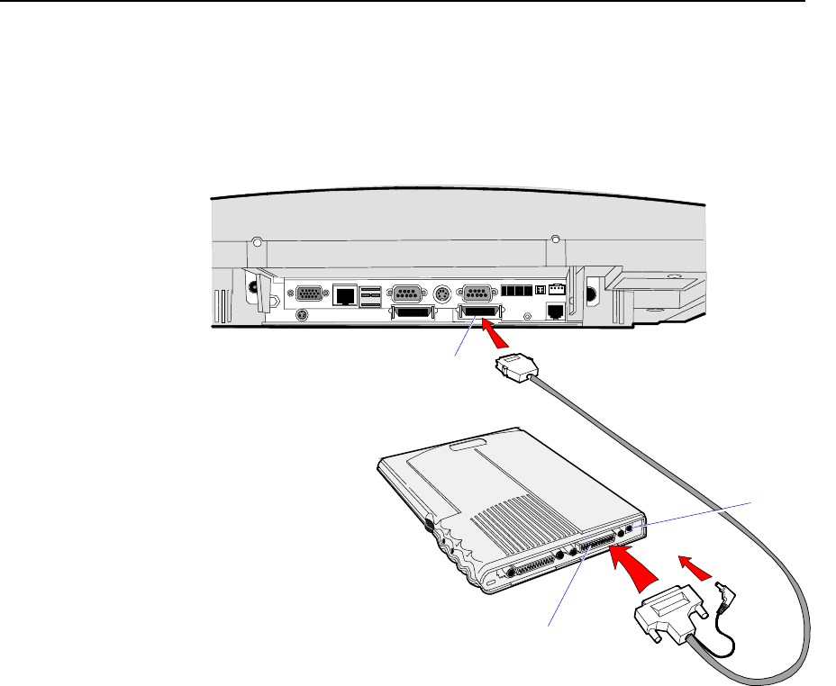
5-2 Chapter 5: BIOS Updating Procedures
Updating Procedures
1. Connect the external CD-ROM (2336-K007) drive to the parallel
port on the terminal.
2. Connect the power connector to the CD-ROM drive.
18250
Parallel Connector
Parallel Connector
Power
Connector
Note: The parallel port on the 7454 is the Customer Display port.
Therefore, if your terminal is configured with a Customer Display, you
must temporarily disconnect it in order to use the CD-ROM drive.
3. Apply power to the terminal so the CD-ROM drive can be opened.
4. Insert the BIOS update CD.
NCR BIOS and BIOS Update Software
LPIN: A370-0022-0100
5. Boot the terminal.

Chapter 5: BIOS Updating Procedures 5-3
6. Press F2 at the screen prompt to enter the Setup Utility.
7. In the Advanced menu, select I/O Device Configuration.
8. Verify that the LPT 1 Mode is set to ECP.
9. Go back to the Advanced menu, select Multiple ROM Menu.
10. Set the Parallel CD-ROM Boot to Enabled.
11. Exit Setup and Save Changes.
As the terminal reboots, you should see a message during boot
indicating that the CD-ROM has been recognized:
Micro Solutions BACKPACK CD-ROM v0.3
. . .
Booting from BACKPACK CD
Starting MS-DOS
12. Follow the screen prompts on the client to update the BIOS. You
can select two methods to run the update program.
• Automatic BIOS Update – update process runs unattended
Note: You see a prompt for terminal model and serial number
information. If the program detects invalid information in the
current BIOS, or if you are replacing the Processor Board, there
is not model/serial number information in the BIOS.
Important: Model/Serial Number is mandatory for FitClient
operation.
• Interactive BIOS Update – permits you to input/replace the
model/serial number information that is stored in the BIOS.
Note: Model/Serial number data that is currently stored in the
BIOS is displayed during power up.
13. When you get the green window, this indicates a successful update.
14. Remove the CD and then press any key to reboot.
13. When the system reboots, press F2 at the screen prompt to enter
Setup.
14. In the Exit menu, select Load Setup Defaults.
15. Exit Setup and Save Changes.

5-4 Chapter 5: BIOS Updating Procedures
BIOS Crisis Recovery
The procedures below provide a way to restore the BIOS resulting
from a non-recoverable condition.
Note: Use this BIOS crisis recovery procedure only for a
NON-RECOVERABLE BIOS failure. A non-recoverable BIOS state
typically results from power loss during a flash BIOS update process.
This is a rare occurrence and should not be confused with other
hardware errors that cause a no video state. This procedure is not
intended to be used for changing or upgrading an operational BIOS.
Required Hardware
Part Number Part Name Use
PC with at serial port Download BIOS
497-0408349 Cable, 9-Pin Female to 9-Pin
Female RS232 PC to terminal
connection
497-0411000 Cable, Parallel Interface 7454 parallel port to
Dongle connection
497-0413418 Parallel Dongle Forces BIOS recovery
497-0414184 POS Connector Board 7454 parallel port
(not required if
already present)
Required Software
Acquire the following software from NCR.
NCR 74xx BIOS and BIOS Update Software
LPIN: A370-0022-0100, Release 3.0 or later
P/N: 497-0424310
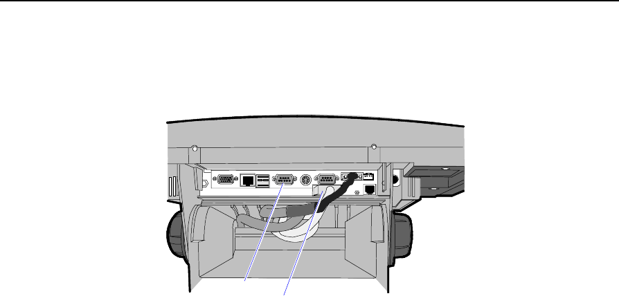
Chapter 5: BIOS Updating Procedures 5-5
Recovery Procedures
1. Connect the Parallel I/F Cable to the parallel (Customer Display)
connector on the terminal.
16993
Customer
Display
RS-232
(Com 1)
Note: The parallel connector on the 7454 terminal is used for the
Customer Display. If the terminal is equipped with a Customer
Display you must temporarily disconnect the display cable. If the
terminal is not equipped with a Customer Display then it is likely
that the terminal does not have a parallel connector and you will
have to install the POS Connector Board.
See the NCR 7454 Retail Terminal Hardware Service Guide
(B005-0000-1342) for information how to open the terminal and
install the POS Connector Board.
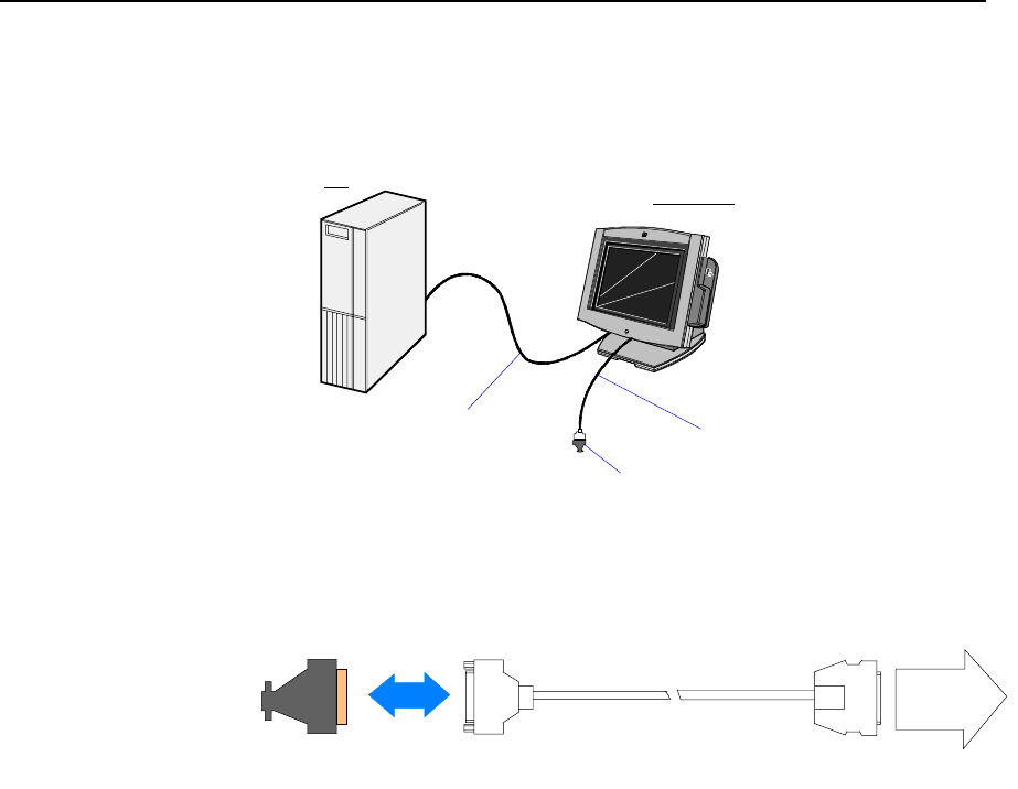
5-6 Chapter 5: BIOS Updating Procedures
2. Connect the two machines with the RS-232 cable. Use COM Port 1
on both machines (COM1 is next to the USB ports on the 7454).
16991
NCR 7454
PC
Parallel Dongle
Parallel I/F Cable
RS-232 Cable
3. Connect the Parallel Dongle to the Parallel I/F Cable.
16992
497-0411000
25-pin
D-Shell
Receptacle
28-pin
Sub-Miniature
D-Plug
Parallel
Port
Parallel
Dongle
4. Boot the PC in the DOS mode with CD-ROM support.
Note: The PC must be running in the DOS mode (not in a Windows
DOS box) for the software to operate correctly.
5. Insert the BIOS update CD into the PC.
NCR BIOS and BIOS Update Software
LPIN: A370-0022-0100
6. Apply power to the terminal.
7. On the PC, change directory to the CD-ROM drive.
E: [Enter]

Chapter 5: BIOS Updating Procedures 5-7
8. Enter the update command:
EMBflash [Enter]
9. Select the number for the 7454 terminal from the menu list:
1) 7454
2) 7401
3) 7452
4) 7453
5) 7455
6) 7460
7) 7451
8) 7456
1 [Enter]
A blue screen displays as the program runs, showing the program
progress, followed by a green screen, indicating a successful load.
PhoenixPhlash Status
PRESS ANY KEY TO EXIT
Flash memory has been successfully programmed
19502
The Class/Model/Serial # information is deleted using the Crisis
Recovery procedure. Use the normal BIOS update procedures, as
discussed earlier in this chapter, to restore the information.
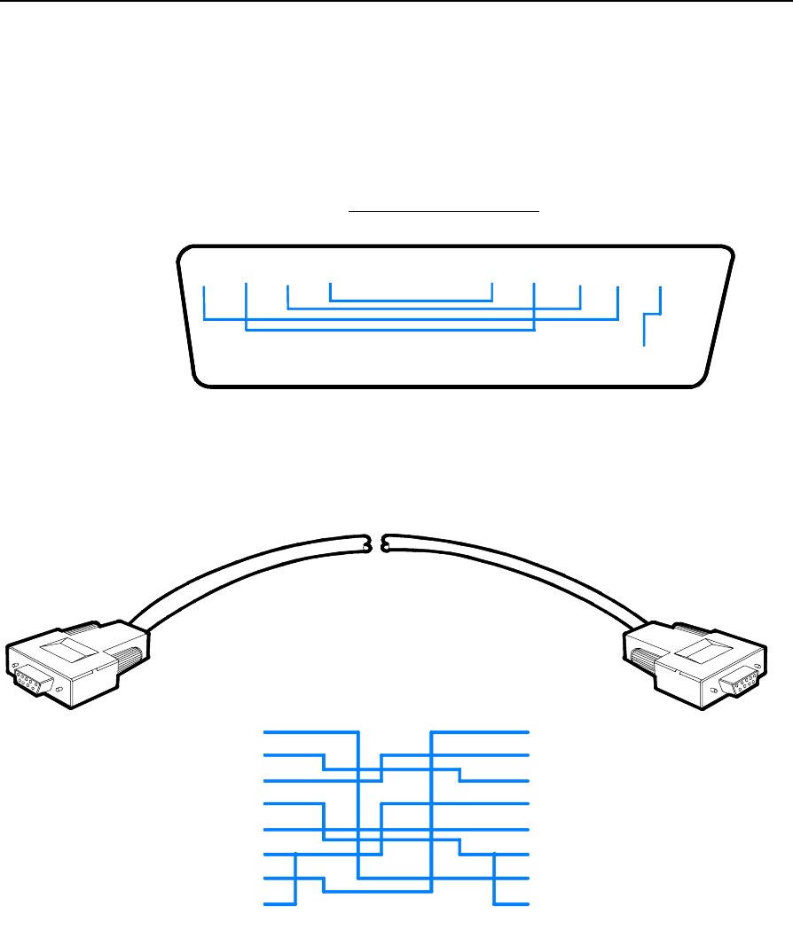
5-8 Chapter 5: BIOS Updating Procedures
Cable/Connector Pin-Out Information
Parallel Dongle
19513
25-Pin D-shell Receptacle
(Viewed from wiring side)
25 24 23 22 21 20 19 18 17 16 15 14
13 12 11 10 9 8 7 5 4 3 2 16
RS-232 Cable
19512
1
2
3
4
5
6
7
8
1
2
3
4
5
6
7
8
P1 P2
9-Pin
D-shell
Receptacle
1
6
5
9
P1 P2
1
6
5
9
9-Pin
D-shell
Receptacle

Chapter 5: BIOS Updating Procedures 5-9
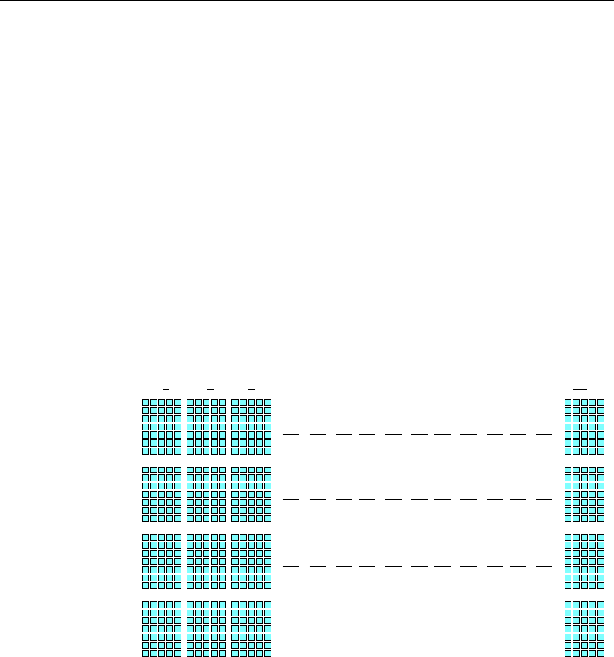
Chapter 6: NCR 7454 4x20 Customer Display
Introduction
This chapter defines the character sets and supported commands. The
NCR 7454 4x20 Customer Display is IEEE 1284 Compatible and
supports Extended Capability Parallel (ECP).
Viewing Area The characters are arranged in 4 rows of 20 characters. Each character
is a 5x7 dot matrix.
16674
1 2 3 20

6-2 Chapter 6: NCR 7454 4x20 Customer Display
Diagnostics Power-Up Diagnostics occur soon after the hardware reset circuitry is
released, or when a Reset Display command is received from the host
software. When the hardware is powered down, all registers and
memory are lost. The display is not capable of any kind of power
recovery back to a previous state. As a part of the Power-Up
Diagnostics, the working registers and variables are initialized (set to
zero).
The self-diagnostics include:
1. Micro-controller Test
The Busy line is set active at the beginning of the test. The first test
is Exclusive-ORing all internal program memory locations and the
result of the test is zero. Any unused bytes in the summed page are
always programmed with null values so that they do not have an
impact on the execution of the test. An internal RAM test writes a
varying numerical value to each RAM location. The pattern must
show that all RAM locations can be uniquely addressed. All RAM
will be written. After the write phase is complete, a read phase
begins to ensure the writes held. If an error is discovered, testing
halts and the firmware begins executing a forever do nothing loop.
2. Display Test
The display will run an extra test that turns on all pixels on the
display (character cells) for about two seconds and then displays
the part number and the firmware version “008-0221552, V1.00.01”
for another two seconds. This permits a user to examine the display
for any pixel failure. The unit does not have the capability to
determine if the Display Test passed. Once diagnostic testing is
completed, the line states will be returned to normal and the
firmware branches to its idle routine.
Note: When the I/F receives a Reset command, only Step 1 is
executed. The Display Test is not executed.
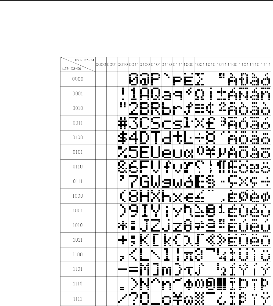
Chapter 6: NCR 7454 4x20 Customer Display 6-3
Character Set
Page 1 – International
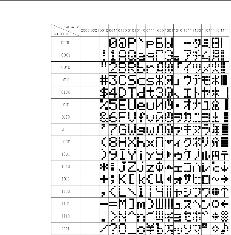
6-4 Chapter 6: NCR 7454 4x20 Customer Display
Page 2 – Japanese
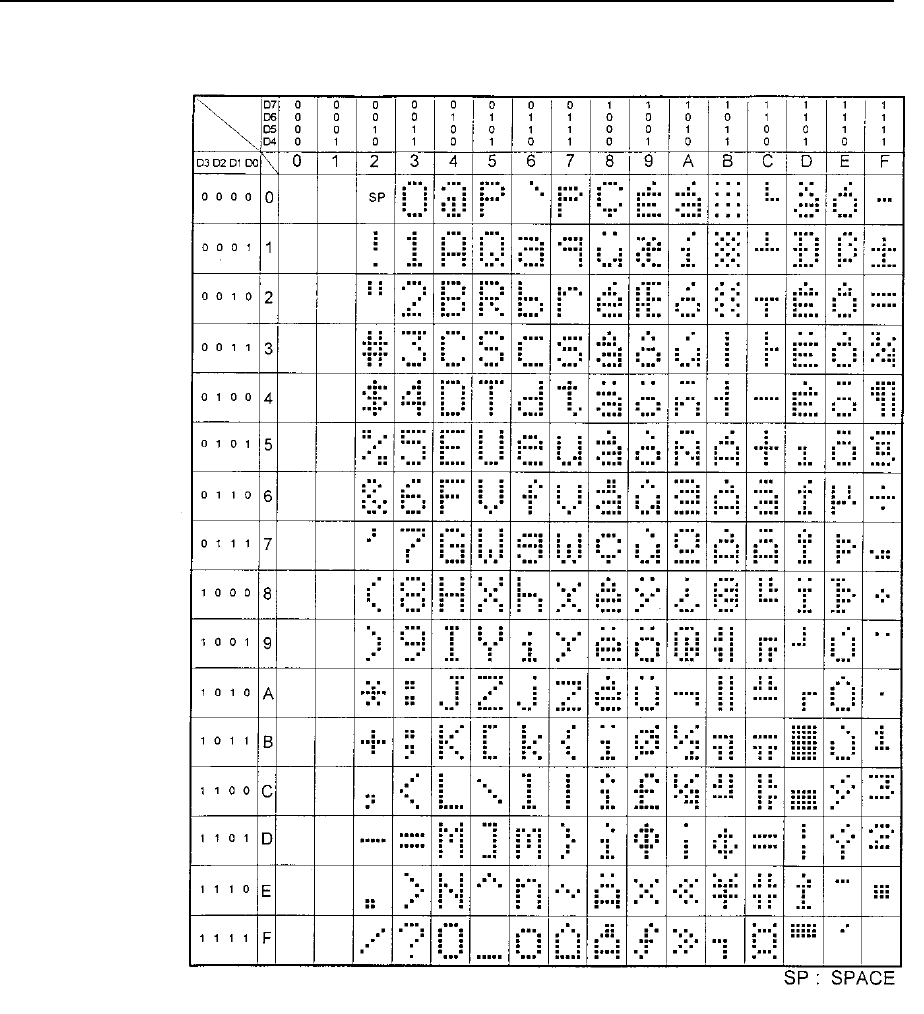
Chapter 6: NCR 7454 4x20 Customer Display 6-5
Page 3 – Code Page 850

6-6 Chapter 6: NCR 7454 4x20 Customer Display
Command Descriptions
Structure/Logic Description
The Retail VFD firmware is comprised of operating system type
services such as common subroutines, interrupt service routines, and
data processing routines. Normally, the firmware is always active
refreshing the Retail VFD to keep display data visible. The firmware
will also act on interrupts due to host parallel communication. This
communication is in the form of commands from the host to the Retail
VFD that require the Retail VFD to modify the display appearance.
The Retail VFD firmware uses a micro-controller and interfaces to
parallel links.
Host/Retail VFD Command Interface
The Retail VFD accepts two types of data; display data and command
data. If a byte received from the host is any character except ESC (0x1B)
character, it is processed as a character and displayed on the Retail
VFD. If an ESC character (0x1B) is received, the subsequent byte(s) is
processed as a command. If the subsequent byte is an invalid
command it will be ignored. If an ESC is received, but no subsequent
byte is received within ten seconds, the firmware will ignore it.
Note that each command consists of at least two bytes. The first byte
(0x1B) is a command identifier indicating the next byte(s) is a
command byte. The command byte may be followed by parameter or
data bytes depending on the command. It is only valid to receive an
ESC (0x1B) as a command identifier.
The following table describes the supported Retail VFD commands.

Chapter 6: NCR 7454 4x20 Customer Display 6-7
Command Function Return Status/String
1B 01 Reset Display No
1B 02 Erase Display No
1B 03 Invalid Command No
1B 04 Set Diagnostic State No
1B 05 Set Display State On No
1B 06 Set Low Power State On (Default) No
1B 07 Enable Cursor No
1B 08 Disable Cursor (Default) No
1B 09 Set Screen Save Blank (Default) No
1B 0A Set Screen Save Walk No
1B 0B Turn On Screen Save No
1B 0C Disable Screen Save Feature No
1B 0D Enable Character Blink No
1B 0E Disable Character Blink (Default) No
1B 0F Move Cursor Left No
1B 10 Move Cursor Right No
1B 11 Move Cursor Up No
1B 12 Move Cursor Down No
1B 13 Set Cursor Position No
1B 17 Brightness Adjustment (Default = 5) No
1B 18 Read Display ID Yes
1B 19 Read Display ID String Yes
1B 20 Select Character Set 1 (Default) No
1B 21 Select Character Set 2 No
1B 22-32 Reserved No
1B 38 Read Display Data String Yes

6-8 Chapter 6: NCR 7454 4x20 Customer Display
Reset Display
Format: 1B 01
Description: This command executes the power-down power-up diagnostic
sequence. The BUSY line is set to active condition. The micro-controller
test consists of a sum-check test on the ROM and a write/read test on
the RAM. After executing the command, the display screen is cleared,
the cursor moves to the 0 position, the BUSY line is set to inactive
conditions, and all registers and variables are initialized. Note that the
screen is cleared during this command. If a host needs previous data
redisplayed, the host must resend the previous data after this
command has completed.
Erase Display
Format: 1B 02
Description: This command clears all of the displayed characters by writing a space
to each display position. A space is defined as character 0x20 of the
current character set. The cursor moves to the 0 position.
Invalid Command
Format: 1B 03
Description: This in now an invalid command.

Chapter 6: NCR 7454 4x20 Customer Display 6-9
Set Diagnostic State
Format: 1B 04
Description: This state is exclusive from the On and Low Power states. This
command causes the firmware to display the current NCR part number
and firmware version of the device. For example, the current part
number and firmware version of the device are 008-0221537 and
V1.00.01) for two seconds and then step through each installed 256-
character set (default and user defined) displaying one character at a
time on all 40 display positions at a rate of about one character per
second. Start with the currently selected character set and then display
all of the characters from the other sets the same way. This continues
until one of the other state commands is performed. Prior display data
is saved and can be restored be sending the Turn On (state 3) com-
mand.
Set Display State On
Format: 1B 05
Description: This state is used for normal run-time conditions. This operation
instructs the firmware to leave one of the other states and begin
performing normal refresh operations. There may be a slight delay
before the VFD reaches the specified brightness setting when exiting
the Low Power State. This delay should not exceed 1 second from the
time the command is received until the time the VFD reaches the
specified brightness.
Highest priority is given to refresh operations and a lower priority is
given to host communications. Host communications still work, but if a
large amount of data is to be programmed in a very short time frame, it
would work faster if the Blank State was programmed prior to the
information transfer.
The Screen Save feature may be in force during the Display On state.
This means that after about five minutes of no new display activity, the
Screen Save feature could take over and cause the display to go blank
or begin walking from right to left.

6-10 Chapter 6: NCR 7454 4x20 Customer Display
Set Low Power State On
Format: 1B 06
Description: This state is used to reduce Retail VFD power consumption and extend
the life of the Retail VFD. Power is only removed from the VFD and the
display will not be refreshed. The Retail VFD controller is still fully
operational and will continue to accept commands. This command
causes the firmware to blank or turn off the Retail VFD. Display data
can be processed while the display is in the Low Power state, but it will
not appear until the Low Power state is changed. The displayed
character(s) states is preserved so that upon leaving the Low Power
State the display is restored. To leave the Low Power State, one of the
other state commands must be received. This is the default state for the
Retail VFD after power-up.
Enable Cursor
Format: 1B 07
Description: This command causes a flashing cursor to be used whenever the
Display On state is in force. When the cursor is enabled, the firmware
will show a visible flashing cursor at the current cursor position. The
flashing cursor should be visible for one second and then the character
at the cursor position should be visible for one second. The effect is to
alternate between the character and the cursor. The cursor is defined as
character 5FH of whatever character set is currently chosen. For the
two supported character sets, the cursor is the bottom row of pixels
turned on. For a user defined character set, the cursor will be whatever
is defined as character 5FH of the character set. When the cursor is
enabled, it overwrites the character at the cursor position. If the cursor
is disabled, the character at the cursor position is left visible.
Disable Cursor
Format: 1B 08
Description: This command causes the cursor to be turned off. This is the default
state for the cursor after power-up. A disabled cursor does not
overwrite a displayed character.

Chapter 6: NCR 7454 4x20 Customer Display 6-11
Set Screen Save Blank
Format: 1B 09
Description: This command is intended to preserve the life of the display hardware
unit. The firmware maintains a five-minute timer that triggers this
feature. The Screen Save feature can be disabled through a command
from the host software. When the feature is not disabled, two specific
options exist. The Set Screen Save Blank operation causes the display to
go blank when the timer expires. When the firmware receives the
command code, the Screen Save mode is canceled and the five-minute
timer is established. Screen Save Blank removes power from the Retail
VFD and does not refresh the display in the same manner as the Set
Low Power On command. At power up, the timer is established at five
minutes and Screen Save Blank is established as a default. The five
minute timer is not reset by any invalid or incorrect command.
Set Screen Save Walk
Format: 1B 0A
Description: This command causes the visible display to walk right to left when the
Screen Save timer expires (five minutes). The characters on the display
will appear to walk across the corresponding display row from right to
left. The four lines in the 4x20 Display will walk in parallel completely
off the left side of the display and then the four lines will appear to
come back from the right. If the display is space filled, then no effect is
perceived even though the walking is taking place. The Screen Save
Blank mode is the default mode after power up.
Turn On Screen Save
Format: 1B 0B
Description: This command causes the one of the screen save functions (Set Screen
Save Blank or Set Screen Save Walk) to activate immediately rather
than waiting for the screen save timer to expire. If the Disable Screen
Save Option command is in effect when this command is issued, it is
canceled and the screen saver is enabled and activated immediately.

6-12 Chapter 6: NCR 7454 4x20 Customer Display
Disable Screen Save Option
Format: 1B 0C
Description: The firmware will cease to keep time for the screen save activity from
the host software and the display will neither go blank nor begin to
walk due to inactivity from the host. This command can be canceled by
the Turn On Screen Save, Set Screen Save Blank, and Set Screen Save
Walk commands.
Enable Character Blink
Format: 1B 0D
Description: The blink attribute is the only modifier that is supported for the display
character positions. The attribute itself is not necessarily programmed
with each new character code. Rather, each time a new character is
received, the current setting of the character blink operator is adopted
as the working attribute for the new character. If a new character is
received while character blink is enabled, the new character will blink.
This makes it possible to have a display with both blinking and non-
blinking characters. The blink period is one second on and one second
off. All characters that are blink enabled, blink at the same time. The
only way to cause an existing character to start or stop blinking is to set
up the character blink operator, locate the cursor to the correct
character, and resend the individual character code.
Disable Character Blink
Format: 1B 0E
Description: This command counteracts the Enable Character Blink. The firmware
will implement all new character codes with an on and holding
character presentation. On power up, the character blink modifier is
defaulted to disabled.

Chapter 6: NCR 7454 4x20 Customer Display 6-13
Move Cursor Left
Format: 1B 0F
Description: Moves the cursor one position to the left. When the cursor is at the left
end of the rows 2-4, it moves to the right end of the row above it. When
the cursor is at the left end of the row 1, it moves to the right end of the
row 4. The cursor location always indicates the position of the next
character to be displayed, whether the cursor is enabled and blinking
or not. After each character is displayed, the firmware performs a
logical Move Cursor Right command.
Move Cursor Right
Format: 1B 10
Description: Moves the cursor one position to the right. When the cursor is at the
right end of the row 1-3, it moves to the left end of the next row. When
the cursor is at the right end of the row 4, it moves to the left end of the
row 1. The cursor location always indicates the position of the next
character to be displayed, whether the cursor is enabled and blinking
or not. After each character is displayed, the firmware performs a
logical Move Cursor Right command. When the cursor is at the right
end of the row 4, it moves to the left end of the row 1 and operates in
an Overwrite Mode. (i.e., The next character sent to the display will
overwrite the character in the left end of the row 1.)
Move Cursor Up
Format: 1B 11
Description: Moves the cursor up one line. When the cursor is on the row 2-4, the
cursor is moved to the same column on the row above it. When the
cursor is on the row 1, the cursor is moved to the same column on the
row 4. The cursor location always indicates the position of the next
character to be displayed, whether the cursor is enabled and blinking
or not. After each character is displayed, the firmware performs a
logical Move Cursor Right command.
6-14 Chapter 6: NCR 7454 4x20 Customer Display
Move Cursor Down
Format: 1B 12
Description: Moves the cursor down one line. When the cursor is on the 1-3, the
cursor is moved to the same column on the next row. When the cursor
is on the row 4, the cursor is moved to the same column on the row 1.
The cursor location always indicates the position of the next character
to be displayed, whether the cursor is enabled and blinking or not.
After each character is displayed, the firmware performs a logical
Move Cursor Right command.
Move Cursor To Specified Position
Format: 1B 13 nn
Range: 00 ≤ nn ≤ 4F (hex)
Description: Moves the cursor to the specified position. Position 0 is the upper
leftmost position and position 4F is the lower rightmost position. Any
value outside this range will be discarded, the command will be
ignored, and the cursor will not be moved. The cursor location always
indicates the position of the next character to be displayed, whether the
cursor is enabled and blinking or not. After each character is displayed,
the firmware performs a logical Move Cursor Right command. The
character positions are shown below.
16675
123 4567890A0B0C0D0E0F10111213
15 16 17 18 1914
0
1A 1B 1C 1D 1E 1F 20 21 22 23 24 25 26 27
28 29 2A 2B 2C 2D 2E 2F 30 31 32 33 34 35 36 37 38 39 3A 3B
3C 3D 3E 3F 40 41 42 43 44 45 46 47 48 49 4A 4B 4C 4D 4E 4F

Chapter 6: NCR 7454 4x20 Customer Display 6-15
Brightness Adjustment
Format: 1B 17 nn
Range: 01 ≤ nn ≤ 05
Description: Adjusts the brightness of the entire display. Individual characters or display
positions will not be adjusted. On power up, the default brightness setting is 5
(100%).
Nn Brightness
01 0%
02 25%
03 50%
04 75%
05 100%
Read Display ID Byte
Format: 1B 18
Returns: 0x8E
Description: This command is a request for the Retail VFD to return a identifier. The
Retail VFD returns one byte (0x8E) that identifies the Retail VFD as a
4x20 with 5x7 dot matrix.
Read Display ID String
Format: 1B 19
Returns: 0x1D, "NCR_008-0221552,_F/W_V1.00.01"
Where 0x1D is a 1 byte string length indicator which indicates the
length of the string that follows the string length indicator. For
example, 1DH characters are sent after the string length indicator.
Note: “_”indicates a space character (20H). The quotation marks “” are
not part of the string and are not returned.
Description: This command is a request for the Retail VFD to return an ASCII string
with detailed product information.

6-16 Chapter 6: NCR 7454 4x20 Customer Display
Display ESC Character
(Not a supported command)
Format: 1B 1B
Description: This command is a request for the ESC character to be displayed to the
current cursor position.
Select Character Set n
Format: 1B 20 - 1B 21
Description: This set of command chooses one of the two supported internal
character sets. Character set 1 is defined as Page 1(International),
character set 2 is defined as Page 2(Japanese). Character set selection is
dynamic. Host software can switch between character sets at any time.
Switching between sets does not erase or change the display. This
means characters from multiple character sets may be on a display. The
default character set is Page 1(International).
Read Display Data String
Format: 1B 38
Returns: 0x50, "xxx---------xxxxx"
Where 0x50 is a 1 byte string length indicator which indicates the length
of the string that follows the string length indicator. For example, 50H
characters are sent after the string length indicator. Note: The quotation
marks “” are not part of the string and are not returned.
Description: This command is a request for the Retail VFD to return an ASCII string
which are being displayed on the Retail VFD.

Appendix A: Cables
Cable Index
Corporate ID Part Number Description
1416-C041-0030 497-0008623 Ethernet 10/100BaseT
1416-C262-0040 497-0404832 2010 coin dispenser
1416-C266-0040 497-0407943 9-pin female to 9-pin female
RS-232
1416-C266-0152 497-0409379 7193 RS-232 50' 9-pin female to 9-
pin female
1416-C320-0030 006-8601011 Cord set – SEV plug with straight
“BM” power
1416-C321-0030 006-8601012 Cord set – United Kingdom plug
with straight “BM” power
1416-C322-0030 006-8601019 Cord set – Australian cable with
straight “BM” power
1416-C323-0030 006-8601010 Cord set – International plug
with straight “BM” power
1416-C325-0030 006-1009037 Cord set – Power, US
1416-C337-0010 497-0407427 RS-232 interface, integrated
1416-C337-0040 497-0407429 RS-232 interface, remote
1416-C337-0152 497-0407430 RS-232 interface 50'
1416-C359-0007 497-0408349 RS-232 (27") 9-pin female to 9-pin
female
1416-C372-0006 497-0409394 Dual cash drawer (Y-cable)
1416-C373-0080 497-0409432 25' cable

A-2 Appendix A: Cables
Corporate ID Part Number Description
1416-C374-0040 497-0409433 14' cable
1416-C408-0030 230-0113955 Power, SEV
1416-C409-0030 230-0113956 Power, UK rectangular
1416-C411-0030 006-1012224 Power, international
1416-C417-0040 497-0411815 Printer extender, 9-pin female to
25-pin female
1416-C418-0040 497-0411816 Printer extender, 25-pin male to
25-pin female
1416-C419-0030 250-0023191 Power, 120V twist lock
1416-C420-0030 008-0218043 Power – Japan w/ lock plug
1416-C422-0030 006-1002021 Power – US
1416-C464-0006 497-0413011 Backpack CD-ROM, Parallel
1416-C472-0006 497-0411000 Parallel interface
1416-C528-0010 497-0415949 USB, 1 meter
1416-C528-0040 497-0415950 USB, 4 meter

Appendix B: Feature Kits
7454 Kits Below is a comprehensive list of the optional hardware Feature Kits
that can be installed in the customer environment. Kit installation
instructions (for those requiring instruction) are available on the
Information Products web sites.
• NCR Intranet: http://inforetail.atlantaga.ncr.com
• Internet: http://www.info.ncr.com
To locate the installation guides on these sites:
1. Select General Search.
2. Select the Kit Instructions icon.
3. In the Kit Title field, enter the Kit Title.
Example: Flash
or
In the Kit Number field, enter the Kit Number.
Example: 7454-K040
4. Select Search
The file can be viewed online by left-mouse clicking on the pub
title, or if you prefer to download the entire file you can right-
mouse click on the title then select the Save Target as... option.
If you aren’t sure of the title of number you can display all kits
associated with a terminal product class by:
1. In the Class drop-down list, select the Class of the terminal.
Example: 7454
2. Select Search.

B-2 Appendix B: Feature Kits
Kit Index
Kit Number Part Number Description
2010-K020-V001 497-0414206 Coin tray
2126-K161-V001 603-6211364 C-3 till
2126-K302-V001 603-6211312 C-3 till, lid with lock
(2188-K202-V001)
2189-K052-V002 497-0009697 Slip tray (7450 G13)
2189-K053-V002 497-0009695 Coin tray (7450 G13)
2189-K060-V001 497-0009209 Till 2 ½
2189-K061-V001 497-0009210 Lid 2 ½
2330-K340-V001 497-0416464 WaveLAN II Turbo 11 Mbs PCMCIA
card for USA & Canada
2330-K341-V001 497-0416466 WaveLAN II Turbo 11 Mbs PCMCIA
card for Japan
2330-K350-V001 497-0412349 Range extender antenna
2336-K001-V001 497-0411988 Ethernet to RS-232 port server
2336-K007-V002 497-0421213 Informa CD-ROM
2336-K008-V001 497-0413014 USB to RS-232 port server
2336-K012-V001 497-0413710 USB to RS-232 2 port server
2336-K016-V001 230-0145388 Hand-held scanner (12 V power)
2336-K019-V001 497-0417069 Mouse, RS-232
2336-K022-V001 497-0417043 Teleqip coin dispenser base unit &
RS-232 cable (100V)
2336-K030-V001 497-0417048 Coin cartridge – US 340403

Appendix B: Feature Kits B-3
Kit Number Part Number Description
2336-K031-V001 497-0417051 Coin cartridge – 1 dollar coin, US
standard 340406
2336-K032-V001 497-0417053 Coin cartridge – Canadian 340405
2336-K033-V001 497-0417357 56 K modem, PCMCIA
2336-K455-V001 008-0221553 Remote 256x64 graphic VFD
2336-K600-V001 497-0414963 30 lb POS scale, USA
2336-K610-V001 497-0414964 15 kg POS scale, Canada
2756-K121-V001 497-0409421 Domestic power supply
2756-K122-V001 497-0409434 Y-cable adapter (mouse/keypad)
2756-K124-V001 497-0409422 International power supply
2756-K145-V001 497-0409666 Wall mount bracket for bump bar
2756-K152-V002 497-0409426 KDS cable
2756-K410-V001 497-0413066 SV 2000 CRT video controller
2756-K420-V001 497-0413064 KDS video add-on kit, domestic
2756-K421-V001 497-0413065 KDS video add-on kit, international
2756-K500-V001 497-0413062 KDS base kit, domestic
2756-K501-V001 497-0413063 KDS base kit, international
2756-K523-V001 497-0413067 RS-232 KDS controller
2756-K524-V001 497-0413068 RS-232 KDS controller, international
2756-K800-V001 497-0411009 Wall mount
2756-K801-V001 497-0411008 Ceiling mount
2757-K100-V001 497-0414898 Oasys KDS base kit
2757-K144-V001 497-0417729 Bump bar
2757-K145-V001 497-0414899 OAsys bump bar mounting bracket

B-4 Appendix B: Feature Kits
Kit Number Part Number Description
2757-K150-V001 497-0423521 OAsys KDS base kit with AV1000
card
2757-K200-V001 497-0414900 OAsys video add-on kit
2757-K250-V001 497-0423522 OAsys KDS add-on kit with AV1000
card
2757-K300-V001 497-0414901 10 MB Ethernet card with software
license
5945-K010-V002 497-0414162 Cable – 4 M RS-232 (9-pin D shell)
5945-K012-V001 497-0414163 Cable – 8 M RS-232 (9-pin D shell)
5945-K020-V001 497-0412046 Power supply (120 V, 60 Hz, US/Can)
5945-K025-V001 497-0412800 Power supply (220-240 V, 50 Hz)
5945-K030-V001 497-0412047 Generic keyboard overlay
5945-K150-V001 497-0416018 Electronic payment terminal with
2-track MSR
5945-K350-V002 497-0419112 Electronic payment terminal with
3-track MSR
5992-K095-V002 497-0421692 Stylus
5992-K150-V005 497-0423889 Signature capture plus with 2-track
MSR
7156-K270-V001 497-0408657 Switch button (20 pieces)
7156-K280-V001 497-0408653 Slip table
7158-K301-V001 497-0411975 Power supply (55 W)
7401-K021-V001 497-0422274 32 MB SDRAM service kit
7401-K024-V001 497-0414201 64 MB SDRAM service kit
7401-K025-V001 497-0414202 128 MB SDRAM service kit
7401-K051-V001 497-0413160 Large capacity hard drive

Appendix B: Feature Kits B-5
Kit Number Part Number Description
7401-K060-V001 497-0412202 Dual PCMCIA port
7401-K070-V001 497-0416029 Dual RS-232
7401-K200-V001 497-0412200 High fidelity speaker module
7401-K533-V001 497-0411713 Wall mount bracket (tilt mount)
7452-K183-V001 497-0415241 32 MB flash disk
7453-K002-V001 497-0407633 Modular cash drawer – 2260
7453-K007-V001 497-0414767 Till with lid and lock
7453-K641-V003 497-0413391 Serial modems for 7161 and 7193
printers
7454-K005-V001 497-0424210 Modular cash drawer – midrange,
gray 105, with anti-temper drawer
flange
7454-K040-V001 497-0411474 8 MB flash disk
7454-K101-V002 497-0412005 MSR 3 track ISO
7454-K102-V001 497-0412299 MSR JIS 2 track
7454-K104-V001 497-0427614 3-Track ISO MSR in Black
7454-K451-V003 497-0412278 4x20 low post integrated customer
display in gray (G105)
7454-K452-V001 497-0413077 4x20 high post integrated customer
display in gray (G105)
7454-K453-V001 497-0412209 Remote post 4x20 customer display
(bi-directional) in gray (G105)
7454-K454-V001 497-0427548 4x20 high post integrated customer
display in charcoal gray (CG01)
7454-K455-V401 497-0427547 4x20 low post integrated customer
display in charcoal gray (CG01)

B-6 Appendix B: Feature Kits
Kit Number Part Number Description
7454-K456-V001 497-0414192 4x20 low post remote customer
display in gray (G105)
7454-K457-V001 497-0427615 4x20 high post external customer
display in charcoal gray (CGT01)

Index
—7—
7454 Kits, B-1
—A—
Advanced power management, 1-19
Audio, 1-14
Auto-Logon
Setting, 2-29
—B—
BIOS crisis recovery, 5-4
BIOS default CMOS values, 3-4
BIOS Recovery
crisis recovery procedures, 5-4
using CD-ROM, 5-1
BIOS values
Celeron processor, 3-4, 3-10
Pentium III processor, 3-10
BIOS Versions, 3-1
—C—
Cash drawer
Installation, 2-22, 2-23
CMOS values
Celeron processor, 3-4, 3-10
Pentium III processor, 3-10
Compact Flash, 1-16
Completing the OS Installation (DOS),
2-28, 4-7
Completing the OS Installation
(Win2000), 2-26, 4-5
Completing the OS Installation (Win95),
2-28, 4-7
Completing the OS Installation (Win98),
2-27, 4-6
Completing the OS Installation (WinNT),
2-27, 4-6
Completing the OS Installation (WinXPe),
2-26, 4-5
Configuration diagram, 1-7
Customer Display (4x20), 6-1
Character sets, 6-3
Command descriptions, 6-6
Diagnostics, 6-2
Customer Display Command
Descriptions
Brightness Adjustment, 6-15
Disable Character Blink, 6-12
Disable Cursor, 6-10
Disable Screen Save Option, 6-12
Display ESC Character, 6-16
Enable Character Blink, 6-12
Enable Cursor, 6-10
Erase Display, 6-8
Invalid Command, 6-8
Move Cursor Down, 6-14

Index-2
Move Cursor Left, 6-13
Move Cursor Right, 6-13
Move Cursor to Specified Position, 6-14
Move Cursor Up, 6-13
Read Display Data String, 6-16
Read Display ID Byte, 6-15
Read Display ID String, 6-16
Reset Display, 6-8
Select Character Set n, 6-16
Set Diagnostic State, 6-9
Set Display State On, 6-9
Set Low Power State On, 6-10
Set Screen Save Blank, 6-11
Set Screen Save Walk, 6-11
Turn On Screen Save, 6-11
—D—
dual display implementation, 1-9
—E—
Ethernet 10/100Base-T, 1-10
—F—
Finalizing the Installation after hardware
installation, 2-26
FLASH memory implementation, 1-18
—G—
Gold disk contents, 4-8
—H—
Hard disk drive, 1-29
Hardware monitor, 1-13
Hardware options, 1-4
Features not supported, 1-6
—I—
Installing the Integrated Customer
Display, 2-17
Integrated customer display
Description, 1-22
Internal speaker, 1-29
Interrupts, 3-8, 3-9, 3-17, 3-19
—L—
LAN status LEDs, 1-31
LCD adapter board, 1-21
LCD backlight inverter module, 1-21
—M—
Magnetic stripe reader, 1-14, 1-18
Model number, 1-2
Motion sensor, 1-30
Mounting the terminal
Pedestal-mount, 2-24
MSR, 1-14, 1-18
—O—
Operating System Recovery
Using CD-ROM, 4-1
Operating System Restrictions, 4-9
Operator display
Description, 1-20

Index-3
—P—
PCI expansion header, 1-14
Pentium III connectors, 1-34
Plug and Play, 1-19
POS connector board, 1-30
Features, 1-4
Power LED, 1-17
Power OK LED, 1-31
Power supply
Description, 1-32
Power/status LED, 1-31
Printer Installation, 2-6
Printers, 1-25
Processor board
Connector descriptions, 1-15
Description, 1-8
Features, 1-3
Processor/chip set, 1-8
—R—
Remote customer display
Installation, 2-10, 2-16
Reset switch, 1-29
—S—
Serial mouse
Installation, 2-34
Serial number, 1-2
Serial ports, 1-13
Setup
Default factory settings, 3-3
Eentering with a keyboard, 3-2
Entering without a keyboard, 3-1
Setup utility, 1-19
Speaker module, 1-32
Standby and Hibernate Mode Restriction,
4-9
—T—
Touch screen controller, 1-15
—U—
Universal serial bus, 1-12
USB RS-232 port server, 1-33
—V—
Video subsystem, 1-9
—W—
Wireless LAN communications, 1-11

B005-0000-1256 Dec 2002 Printed on recycled paper
