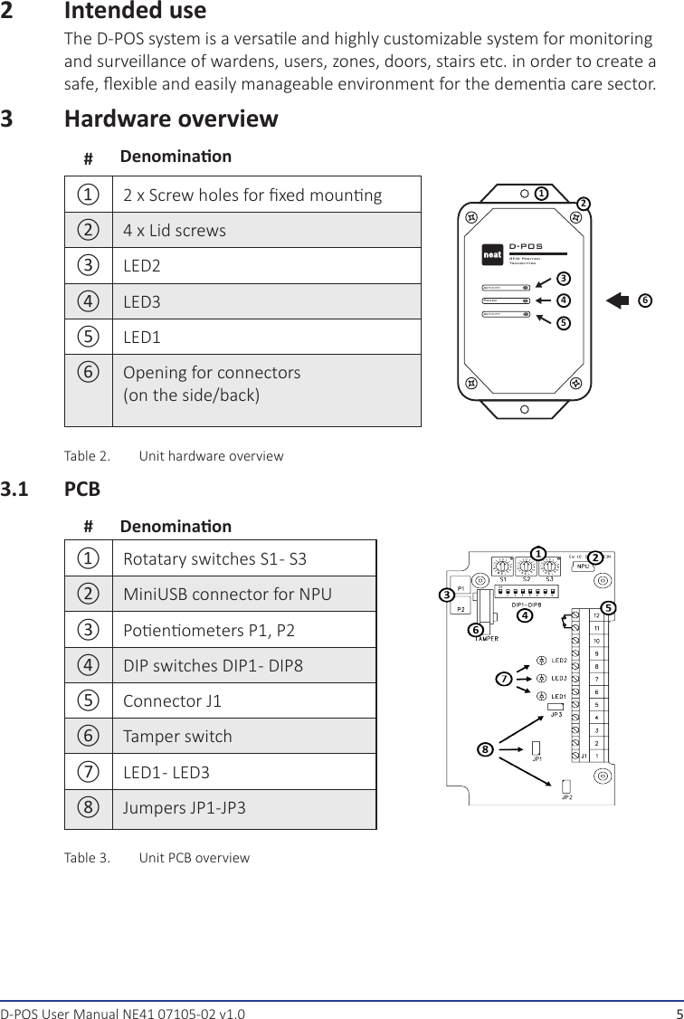
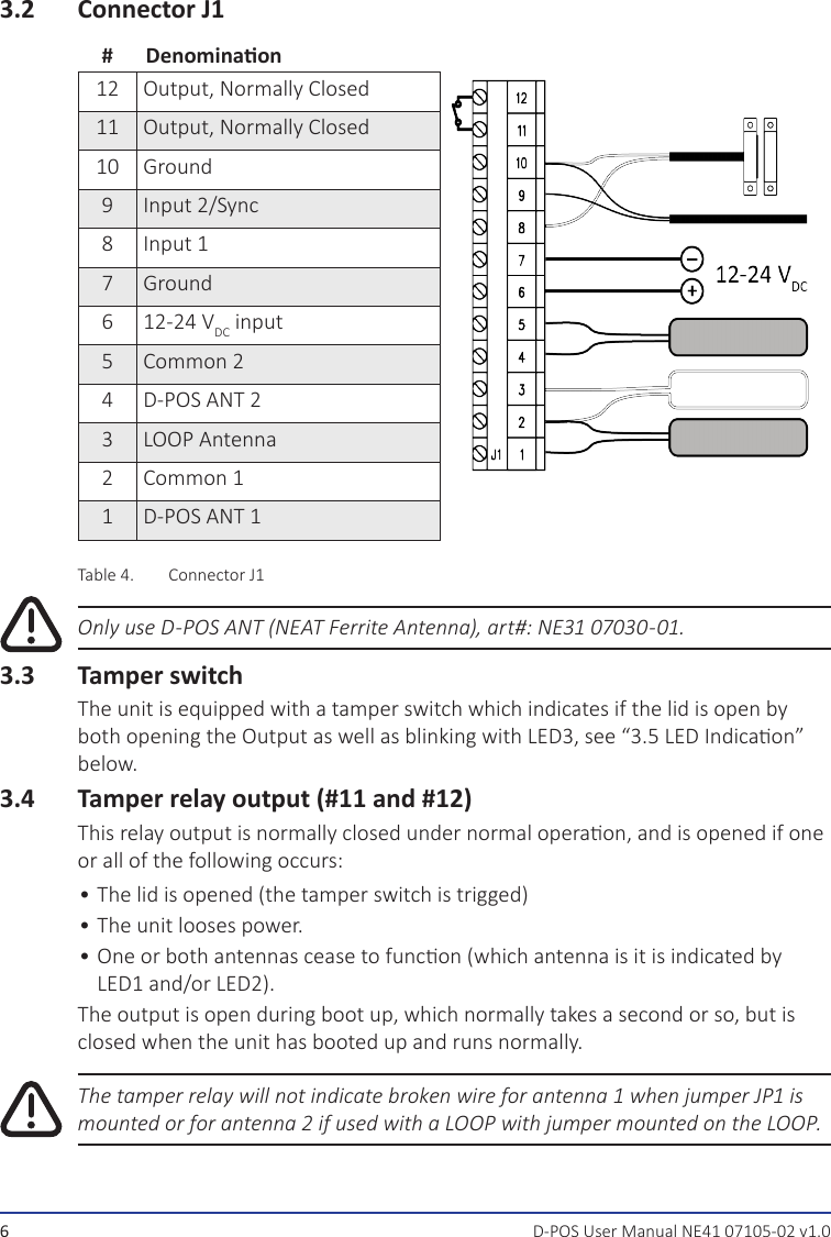
NEAT Electronics 0702901 Magnetic field generator for positioning system User Manual D POS

NEAT Electronics AB Magnetic field generator for positioning system D POS

User manual

D-POSUser ManualNE41 07105-02 v1.0
D-POS User Manual NE41 07105-02 v1.0US NotesFCC ID: 2AGLF0702901Changes or modicaons not expressly approved by the party responsible for compliance could void the user’s authority to operate the equipment.This device complies with part 15 of the FCC Rules. Operaon is subject to the following two condions: (1) This device may not cause harmful interference, and (2) this device must accept any interference received, including interference that may cause undesired operaon.NOTE: This equipment has been tested and found to comply with the limits for a Class B digital device, pursuant to part 15 of the FCC Rules. These limits are designed to provide reasonable protecon against harmful interference in a residenal installaon. This equipment generates, uses and can radiate radio frequency energy and, if not installed and used in accordance with the instrucons, may cause harmful interference to radio communicaons. However, there is no guarantee that interference will not occur in a parcular installaon. If this equipment does cause harmful interference to radio or television recepon, which can be determined by turning the equipment o and on, the user is encouraged to try to correct the interference by one or more of the following measures:• Reorient or relocate the receiving antenna.• Increase the separaon between the equipment and receiver.• Connect the equipment into an outlet on a circuit dierent from that to which the receiver is connected.• Consult the dealer or an experienced radio/TV technician for help.Ulrik Lundberg CEOInformaon in this User manual is subject to change without noce. NEAT Electronics AB reserves the right to change or improve their products and to make changes to the content without obligaon to nofy any person or organizaon of such changes or improvements.NEAT Electronics AB is not responsible for any loss of data, income or any consequenal damage whatso-ever caused.For more informaon, details and descripons, visit our web site:www. neat-group.com/se/en© NEAT Electronics AB 2015All rights reserved.Document number: NE41 07105-02 v1.0Revision date: 2016-11-08ContactNEAT Electronics AB Varuvägen 2 SE-24642 Löddeköpinge SwedenPhone: +46 (0)46 707065Fax: +46 (0)46 707087www.neat-group.com/se/eninfosweden@neat-group.com2
1  Parts in the package2  Intended use3  Hardware overview3.1  PCB3.2  Connector J13.3  Tamper switch3.4  Tamper relay output (#11 and #12)3.5  LED Indicaon3.6  LOOP Antenna4 Installaon5 Sengs5.1  NPU Conguraon5.2  Antenna 2 acvaon5.3  External control5.4  Idencaon Code5.5  Zone Number6  Walk Test Mode7 Important7.1  Safety Notes7.2 Use7.3 Cleaning7.4  Disposal8  Technical dataContentsD-POS User Manual NE41 07105-02 v1.0 3
D-POS User Manual NE41 07105-02 v1.01  Parts in the package#Denominaon①1 x D-POS unit②1 x AC (NE31 07006-22 (12VDC, 1.6A US plug))③1 x Plasc bag with 4 lid screws④1 x This user manualTable 1.  D-POS Kit partsD-POS and its corresponding parts must be installed by a professional er.①②③④4
D-POS User Manual NE41 07105-02 v1.02  Intended useThe D-POS system is a versale and highly customizable system for monitoring and surveillance of wardens, users, zones, doors, stairs etc. in order to create a safe, exible and easily manageable environment for the demena care sector.3  Hardware overview#Denominaon①2 x Screw holes for xed mounngActivityD-POSRFID PositionTransmitterActivityPower123456②4 x Lid screws③LED2④LED3⑤LED1⑥Opening for connectors (on the side/back)Table 2.  Unit hardware overview3.1  PCB#Denominaon①Rotatary switches S1 - S3②MiniUSB connector for NPU③Poenometers P1, P2④DIP switches DIP1 - DIP8⑤Connector J1⑥Tamper switch⑦LED1 -  LED3⑧Jumpers JP1-JP3Table 3.  Unit PCB overview5
D-POS User Manual NE41 07105-02 v1.03.2  Connector J1#Denominaon12 Output, Normally Closed11 Output, Normally Closed10 Ground9Input 2/Sync8Input 17 Ground612-24 VDC input5 Common 24 D-POS ANT 23LOOP Antenna2 Common 11 D-POS ANT 1Table 4.  Connector J1Only use D-POS ANT (NEAT Ferrite Antenna), art#: NE31 07030-01.3.3  Tamper switchThe unit is equipped with a tamper switch which indicates if the lid is open by both opening the Output as well as blinking with LED3, see “3.5 LED Indicaon” below.3.4  Tamper relay output (#11 and #12)This relay output is normally closed under normal operaon, and is opened if one or all of the following occurs:• The lid is opened (the tamper switch is trigged)• The unit looses power.• One or both antennas cease to funcon (which antenna is it is indicated by LED1 and/or LED2).The output is open during boot up, which normally takes a second or so, but is closed when the unit has booted up and runs normally.The tamper relay will not indicate broken wire for antenna 1 when jumper JP1 is mounted or for antenna 2 if used with a LOOP with jumper mounted on the LOOP.6
D-POS User Manual NE41 07105-02 v1.03.5  LED IndicaonThere are three light eming diodes (LED) in D-POS. The acvity LEDs - LED1 and LED2 - are red. The power LED - LED3 - is green. When the D-POS unit is powered on, all three LEDs light up for one second. LED3 burns with a steady green light as long as the power supply is OK and the D-POS unit is working without problems.When the unit is working correctly, LED1 is blinking when antenna 1 is transmit-ng and LED2 is blinking when antenna 2 is transming.If LED3 is blinking with a green light, an error has been detected with the power supply or the antennas, or the D-POS unit is broken or the lid is open (tamper switch is open).If LED1 is blinking with a red light and LED3 is blinking with a green light, there is a problem with antenna 1. If LED2 is blinking with a red light and LED3 is blinking with a green light, there is a problem with antenna 2.3.6  LOOP AntennaA LOOP Antenna is an electrical cable in a loop creang an electrical eld. Max cable length <10 meters and cable area >0.4 mm2 (AWG 21).4  Installaon1.  To change the conguraon of D-POS, remove the lid and make sure the  AC/DC adapter is unplugged. Change the sengs of rotary switches, DIP switches and jumpers as described on page 6 in this manual.2.  Connect a D-POS ANT to screw terminals 1 & 2 OR a LOOP antenna to screw terminals 2 & 3.To use both D-POS ANT and a LOOP Antenna connect D-POS ANT to screw  terminals 4 & 5 and then the LOOP Antenna to screw terminals 2 & 3.3.  If a magnec contact switch is used, connect it to screw terminals 8 & 10.4.  If the RFID eld from two D-POS units overlap, connect a synchronizaon cable to screw terminals 9 & 10 on both D-POS units.5.  Connect the AC/DC adaptor to screw terminals 6 & 7.Only use AC/DC adaptor provided by NEAT or use 12-24 VDC as central  power supply.6.  Close and fasten the lid using the screws supplied.7.  Plug in the AC/DC adaptor in a mains outlet in the apartment.8.  The power LED lights up with a steady green light to indicate power is on.To adjust the rotary switches we recommend a at screwdriver with a 2.4 x 0.5 mm blade. Use max. 10 meters of cable with cable area 0.4 mm2 or more (AWG 21) for ferrite and loop antennas.7
D-POS User Manual NE41 07105-02 v1.05  SengsD-POS is congured with rotary switches S1-S3, DIP switches 1-8 and jumpers JP1-JP3 as shown in 3.1. Basic conguraon of D-POS using switches and jumpers is explained on the next pages.5.1  NPU ConguraonIn some applicaons there may be need for a conguraon that cannot be set up with D-POS on-board switches. One example is when two magnec switches are needed to control one antenna each. In this case a computer with the D-POS Programmer soware and the NEAT USB interface (NPU) must be used.To use computer conguraon, set DIP switch 1 to ON. In this operang mode, sengs made with rotary switches S1-S3 while DIP switches 2-8 are ignored.For more details on how to use D-POS programmer see D-POS and D-ATOM Tech-nical Handbook, document number NE41 08001-02.DIP1 ConguraonON Computer conguraonOFF On-board switchesTable 5.  DIP1 - Conguraon sengs5.2  Antenna 2 acvaonAntenna 2 can be used to extend the coverage area or for a second separate door up to 10 meters away from D-POS. When a second antenna is connected to screw terminals 4 and 5, set DIP switch 4 to ON, otherwise OFF.DIP4 Antenna 2ON AcveOFF Not acveTable 6.  Acvate antenna 28
D-POS User Manual NE41 07105-02 v1.05.3  External controlD-POS has two external inputs which can be connected to closing switches to control RFID transmission. Input 2 can only be used if D-POS is congured with a computer, see “5.1 NPU Conguraon” on page 8.To use input 1 to control RFID transmission (antennas 1 and 2) set DIP switch 2 to ON. DIP switch 3 determines whether RFID transmission shall be acve when the input is open or closed.DIP2 Antennas 1 and 2ON Antennas are controlled by input 1OFF Antennas are always acveTable 7.  DIP2 - congure antenna 1 and 2 posion signalsDIP3 Input 1 modeON Normally open — antennas acve when input closedOFF Normally closed — antennas acve when input openTable 8.  DIP3 - Congure input acvaon state5.4  Idencaon CodeEach D-POS unit must to be idened with a unique code. With the on-board rotary switches S1-S2 and DIP switches 5 and 6 it is possible to select one of 256 dierent idencaon codes.When a computer is used to congure D-POS it is possible to choose one of 65000 dierent idencaon codes.The ID code consists of four hexadeximal digits. The table below shows which code will be transmied by antenna 1 and antenna 2 depending on the values of rotary switch S1-S2 and DIP switch 5 and 6.DIP5 DIP6 Antenna 1 ID code Antenna 2 ID codeOFF OFF S1 S2 0 1 S1 S2 0 1ON OFF S1 S2 0 1 S1 S2 0 2OFF ON S1 0 0 1 S1 0 0 1ON ON S1 0 0 1 S2 0 0 2Table 9.  DIP5 and 6 - antenna posion codes5.5  Zone NumberEach D-POS unit can be congured to belong to one of 16 zones: 0-9, A-F. The zone is selected with rotary switch S3. The zone number is used by D-ATOM to determine if it shall send an alarm or not.The selected zone number will be used for both antenna 1 and antenna 2.9
D-POS User Manual NE41 07105-02 v1.06  Walk Test ModeTo verify the size of the RFID eld, a walk test mode can be acvated with DIP switch 8.When a D-ATOM is inside the RFID eld, its LED will blink once per second. The color of the D-ATOM LED indicates if it is congured to send an alarm when pass-ing an RFID eld with the ID code and zone number transmied by D-POS: red for alarm, green for no alarm.During walk test mode D-ATOM will not make any transmission to D-DOOR, NEO or TREX etc, so do not forget to return DIP switch 8 to OFF posion when RFID eld check is done.DIP 8 Walk Test ModeON AcveOFF Not acveTable 10.  DIP 8 - Congure Walk Test Mode10
D-POS User Manual NE41 07105-02 v1.07  Important7.1  Safety Notes•  Read instrucons prior to use•  Always test the system per instrucons prior to use and always check the  funcon of the product aer making adjustments• This product may not be suitable for all persons.•  This product should not be a substute for the roune visual monitoring  protocol by caregiver and must not be used in situaons where a delay in the arrival of appropriate medical care, could lead to a potenally life-threatening situaon.• Our units are NOT intended for any life support device, thus intending a device whose malfuncon may result in damage to a life.•  Check the device regularly and replace when necessary.•  Do not integrate to other systems other than those specied in this document.• The product will not cause electromagnec disturbances under normal working  condions.•  The product can be placed near other products or devices as long as  mechanical vibraon is not present.7.2  Use• Use only original parts.• Keep away from dust, moist and dirt.• Do not drop, knock, twist or shake the device.• Do not warm up the device or use it near re.• The product may not be painted.• For repairs, contact a NEAT dealer.7.3  Cleaning• All parts in the product kit can be cleaned with a mild soap soluon and a damp cloth. Dry with a dry cloth.• Strong chemicals, alcohol, grease and other harsh substances must not be used when cleaning or handling the parts in the product kit.• The product must be disconnected from the power socket before cleaning.• Aer cleaning, control that the product works properly by sending a test alarm to the alarm receiver/central.7.4  DisposalAt the end of the product’s use life, please dispose of it at appropriate collecon points provided in your country. For disposal or recycling informaon, please contact your local authories or the Electronic Industries Alliance (EIA, www.eiae.org). In the European Union, the bin label indicates that this product should not be disposed of with household waste. It should be deposited at an appropriate facility to enable recovery and recycling or returned to NEAT Electronics.11
8  Technical dataDenominaon DataCurrent 12-24 VDC 1,5AMeasures  130 x 73 x 25 mmWeight  129 gOutput #11, #12Resistancemax (Closed) 16 ΩBlocking voltagemax 60 VDCLoad currentmax 100 mALeakage currentmax (Open) 1 µAIsolaon voltage 1500V

Navigation menu