NEAT Electronics 0702901 Magnetic field generator for positioning system User Manual D POS
NEAT Electronics AB Magnetic field generator for positioning system D POS
User manual
D-POS
User Manual
NE41 07105-02 v1.0

D-POS User Manual NE41 07105-02 v1.0
US Notes
FCC ID: 2AGLF0702901
Changes or modicaons not expressly approved by
the party responsible for compliance could void the
user’s authority to operate the equipment.
This device complies with part 15 of the FCC Rules.
Operaon is subject to the following two condions:
(1) This device may not cause harmful interference,
and (2) this device must accept any interference
received, including interference that may cause
undesired operaon.
NOTE: This equipment has been tested and found to
comply with the limits for a Class B digital device,
pursuant to part 15 of the FCC Rules. These limits are
designed to provide reasonable protecon against
harmful interference in a residenal installaon. This
equipment generates, uses and can radiate radio
frequency energy and, if not installed and used in
accordance with the instrucons, may cause harmful
interference to radio communicaons. However,
there is no guarantee that interference will not occur
in a parcular installaon. If this equipment does
cause harmful interference to radio or television
recepon, which can be determined by turning the
equipment o and on, the user is encouraged to try
to correct the interference by one or more of the
following measures:
• Reorient or relocate the receiving antenna.
• Increase the separaon between the
equipment and receiver.
• Connect the equipment into an outlet on
a circuit dierent from that to which the receiver is
connected.
• Consult the dealer or an experienced radio/TV
technician for help.
Ulrik Lundberg
CEO
Informaon in this User manual is subject to change
without noce. NEAT Electronics AB reserves the
right to change or improve their products and to
make changes to the content without obligaon to
nofy any person or organizaon of such changes or
improvements.
NEAT Electronics AB is not responsible for any loss of
data, income or any consequenal damage whatso-
ever caused.
For more informaon, details and descripons, visit
our web site:
www. neat-group.com/se/en
© NEAT Electronics AB 2015
All rights reserved.
Document number: NE41 07105-02 v1.0
Revision date: 2016-11-08
Contact
NEAT Electronics AB
Varuvägen 2
SE-24642 Löddeköpinge
Sweden
Phone: +46 (0)46 707065
Fax: +46 (0)46 707087
www.neat-group.com/se/en
infosweden@neat-group.com
2

1 Parts in the package
2 Intended use
3 Hardware overview
3.1 PCB
3.2 Connector J1
3.3 Tamper switch
3.4 Tamper relay output (#11 and #12)
3.5 LED Indicaon
3.6 LOOP Antenna
4 Installaon
5 Sengs
5.1 NPU Conguraon
5.2 Antenna 2 acvaon
5.3 External control
5.4 Idencaon Code
5.5 Zone Number
6 Walk Test Mode
7 Important
7.1 Safety Notes
7.2 Use
7.3 Cleaning
7.4 Disposal
8 Technical data
Contents
D-POS User Manual NE41 07105-02 v1.0 3
D-POS User Manual NE41 07105-02 v1.0
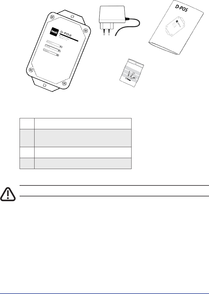
1 Parts in the package
#Denominaon
①1 x D-POS unit
②1 x AC
(NE31 07006-22 (12VDC, 1.6A US plug))
③1 x Plasc bag with 4 lid screws
④1 x This user manual
Table 1. D-POS Kit parts
D-POS and its corresponding parts must be installed by a professional er.
①
②
③
④
4
D-POS User Manual NE41 07105-02 v1.0
2 Intended use
The D-POS system is a versale and highly customizable system for monitoring
and surveillance of wardens, users, zones, doors, stairs etc. in order to create a
safe, exible and easily manageable environment for the demena care sector.
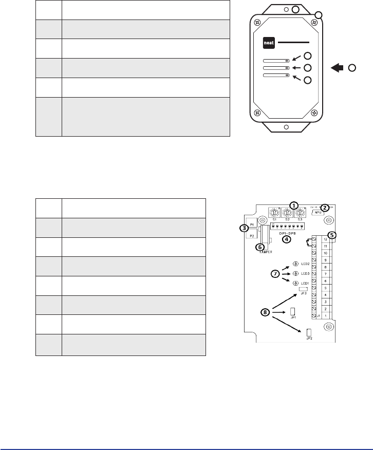
3 Hardware overview
#Denominaon
①2 x Screw holes for xed mounng
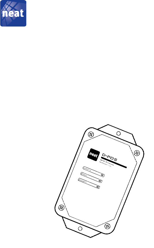
Activity
D-POS
RFID Position
Transmitter
Activity
Power
1
2
3
4
5
6
②4 x Lid screws
③LED2
④LED3
⑤LED1
⑥Opening for connectors
(on the side/back)
Table 2. Unit hardware overview
3.1 PCB
#Denominaon
①Rotatary switches S1 - S3
②MiniUSB connector for NPU
③Poenometers P1, P2
④DIP switches DIP1 - DIP8
⑤Connector J1
⑥Tamper switch
⑦LED1 - LED3
⑧Jumpers JP1-JP3
Table 3. Unit PCB overview
5
D-POS User Manual NE41 07105-02 v1.0
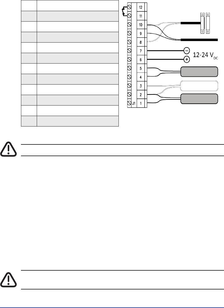
3.2 Connector J1
#Denominaon
12 Output, Normally Closed
11 Output, Normally Closed
10 Ground
9Input 2/Sync
8Input 1
7 Ground
612-24 VDC input
5 Common 2
4 D-POS ANT 2
3LOOP Antenna
2 Common 1
1 D-POS ANT 1
Table 4. Connector J1
Only use D-POS ANT (NEAT Ferrite Antenna), art#: NE31 07030-01.
3.3 Tamper switch
The unit is equipped with a tamper switch which indicates if the lid is open by
both opening the Output as well as blinking with LED3, see “3.5 LED Indicaon”
below.
3.4 Tamper relay output (#11 and #12)
This relay output is normally closed under normal operaon, and is opened if one
or all of the following occurs:
• The lid is opened (the tamper switch is trigged)
• The unit looses power.
• One or both antennas cease to funcon (which antenna is it is indicated by
LED1 and/or LED2).
The output is open during boot up, which normally takes a second or so, but is
closed when the unit has booted up and runs normally.
The tamper relay will not indicate broken wire for antenna 1 when jumper JP1 is
mounted or for antenna 2 if used with a LOOP with jumper mounted on the LOOP.
6

D-POS User Manual NE41 07105-02 v1.0
3.5 LED Indicaon
There are three light eming diodes (LED) in D-POS. The acvity LEDs - LED1 and
LED2 - are red. The power LED - LED3 - is green. When the D-POS unit is powered
on, all three LEDs light up for one second. LED3 burns with a steady green light as
long as the power supply is OK and the D-POS unit is working without problems.
When the unit is working correctly, LED1 is blinking when antenna 1 is transmit-
ng and LED2 is blinking when antenna 2 is transming.
If LED3 is blinking with a green light, an error has been detected with the power
supply or the antennas, or the D-POS unit is broken or the lid is open (tamper
switch is open).
If LED1 is blinking with a red light and LED3 is blinking with a green light, there is
a problem with antenna 1. If LED2 is blinking with a red light and LED3 is blinking
with a green light, there is a problem with antenna 2.
3.6 LOOP Antenna
A LOOP Antenna is an electrical cable in a loop creang an electrical eld. Max
cable length <10 meters and cable area >0.4 mm2 (AWG 21).
4 Installaon
1. To change the conguraon of D-POS, remove the lid and make sure the
AC/DC adapter is unplugged. Change the sengs of rotary switches, DIP
switches and jumpers as described on page 6 in this manual.
2. Connect a D-POS ANT to screw terminals 1 & 2 OR a LOOP antenna to screw
terminals 2 & 3.
To use both D-POS ANT and a LOOP Antenna connect D-POS ANT to screw
terminals 4 & 5 and then the LOOP Antenna to screw terminals 2 & 3.
3. If a magnec contact switch is used, connect it to screw terminals 8 & 10.
4. If the RFID eld from two D-POS units overlap, connect a synchronizaon cable
to screw terminals 9 & 10 on both D-POS units.
5. Connect the AC/DC adaptor to screw terminals 6 & 7.
Only use AC/DC adaptor provided by NEAT or use 12-24 VDC as central
power supply.
6. Close and fasten the lid using the screws supplied.
7. Plug in the AC/DC adaptor in a mains outlet in the apartment.
8. The power LED lights up with a steady green light to indicate power is on.
To adjust the rotary switches we recommend a at screwdriver with a 2.4 x 0.5
mm blade. Use max. 10 meters of cable with cable area 0.4 mm2 or more (AWG
21) for ferrite and loop antennas.
7
D-POS User Manual NE41 07105-02 v1.0
5 Sengs
D-POS is congured with rotary switches S1-S3, DIP switches 1-8 and jumpers
JP1-JP3 as shown in 3.1. Basic conguraon of D-POS using switches and jumpers
is explained on the next pages.
5.1 NPU Conguraon
In some applicaons there may be need for a conguraon that cannot be set
up with D-POS on-board switches. One example is when two magnec switches
are needed to control one antenna each. In this case a computer with the D-POS
Programmer soware and the NEAT USB interface (NPU) must be used.
To use computer conguraon, set DIP switch 1 to ON. In this operang mode,
sengs made with rotary switches S1-S3 while DIP switches 2-8 are ignored.
For more details on how to use D-POS programmer see D-POS and D-ATOM Tech-
nical Handbook, document number NE41 08001-02.
DIP1 Conguraon
ON Computer conguraon
OFF On-board switches
Table 5. DIP1 - Conguraon sengs
5.2 Antenna 2 acvaon
Antenna 2 can be used to extend the coverage area or for a second separate door
up to 10 meters away from D-POS. When a second antenna is connected to screw
terminals 4 and 5, set DIP switch 4 to ON, otherwise OFF.
DIP4 Antenna 2
ON Acve
OFF Not acve
Table 6. Acvate antenna 2
8
D-POS User Manual NE41 07105-02 v1.0
5.3 External control
D-POS has two external inputs which can be connected to closing switches to
control RFID transmission. Input 2 can only be used if D-POS is congured with a
computer, see “5.1 NPU Conguraon” on page 8.
To use input 1 to control RFID transmission (antennas 1 and 2) set DIP switch 2 to
ON. DIP switch 3 determines whether RFID transmission shall be acve when the
input is open or closed.
DIP2 Antennas 1 and 2
ON Antennas are controlled by input 1
OFF Antennas are always acve
Table 7. DIP2 - congure antenna 1 and 2 posion signals
DIP3 Input 1 mode
ON Normally open — antennas acve when input closed
OFF Normally closed — antennas acve when input open
Table 8. DIP3 - Congure input acvaon state
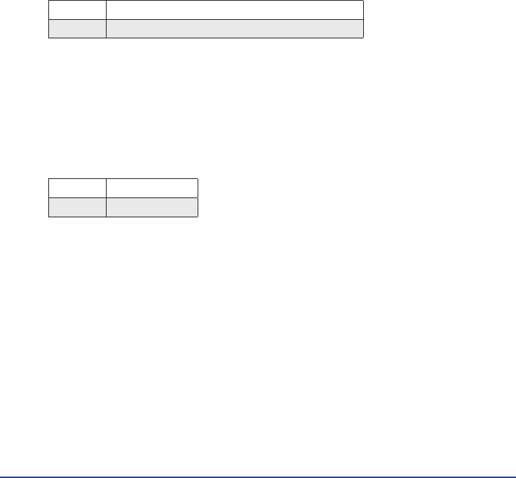
5.4 Idencaon Code
Each D-POS unit must to be idened with a unique code. With the on-board
rotary switches S1-S2 and DIP switches 5 and 6 it is possible to select one of 256
dierent idencaon codes.
When a computer is used to congure D-POS it is possible to choose one of 65000
dierent idencaon codes.
The ID code consists of four hexadeximal digits. The table below shows which
code will be transmied by antenna 1 and antenna 2 depending on the values of
rotary switch S1-S2 and DIP switch 5 and 6.
DIP5 DIP6 Antenna 1 ID code Antenna 2 ID code
OFF OFF S1 S2 0 1 S1 S2 0 1
ON OFF S1 S2 0 1 S1 S2 0 2
OFF ON S1 0 0 1 S1 0 0 1
ON ON S1 0 0 1 S2 0 0 2
Table 9. DIP5 and 6 - antenna posion codes
5.5 Zone Number
Each D-POS unit can be congured to belong to one of 16 zones: 0-9, A-F. The
zone is selected with rotary switch S3. The zone number is used by D-ATOM to
determine if it shall send an alarm or not.
The selected zone number will be used for both antenna 1 and antenna 2.
9

D-POS User Manual NE41 07105-02 v1.0
6 Walk Test Mode
To verify the size of the RFID eld, a walk test mode can be acvated with DIP
switch 8.
When a D-ATOM is inside the RFID eld, its LED will blink once per second. The
color of the D-ATOM LED indicates if it is congured to send an alarm when pass-
ing an RFID eld with the ID code and zone number transmied by D-POS: red for
alarm, green for no alarm.
During walk test mode D-ATOM will not make any transmission to D-DOOR, NEO
or TREX etc, so do not forget to return DIP switch 8 to OFF posion when RFID
eld check is done.
DIP 8 Walk Test Mode
ON Acve
OFF Not acve
Table 10. DIP 8 - Congure Walk Test Mode
10

D-POS User Manual NE41 07105-02 v1.0
7 Important
7.1 Safety Notes
• Read instrucons prior to use
• Always test the system per instrucons prior to use and always check the
funcon of the product aer making adjustments
• This product may not be suitable for all persons.
• This product should not be a substute for the roune visual monitoring
protocol by caregiver and must not be used in situaons where a delay in the
arrival of appropriate medical care, could lead to a potenally life-threatening
situaon.
• Our units are NOT intended for any life support device, thus intending a device
whose malfuncon may result in damage to a life.
• Check the device regularly and replace when necessary.
• Do not integrate to other systems other than those specied in this document.
• The product will not cause electromagnec disturbances under normal working
condions.
• The product can be placed near other products or devices as long as
mechanical vibraon is not present.
7.2 Use
• Use only original parts.
• Keep away from dust, moist and dirt.
• Do not drop, knock, twist or shake the device.
• Do not warm up the device or use it near re.
• The product may not be painted.
• For repairs, contact a NEAT dealer.
7.3 Cleaning
• All parts in the product kit can be cleaned with a mild soap soluon and a damp
cloth. Dry with a dry cloth.
• Strong chemicals, alcohol, grease and other harsh substances must not be used
when cleaning or handling the parts in the product kit.
• The product must be disconnected from the power socket before cleaning.
• Aer cleaning, control that the product works properly by sending a test alarm
to the alarm receiver/central.
7.4 Disposal
At the end of the product’s use life, please dispose of it at appropriate collecon
points provided in your country. For disposal or recycling informaon, please
contact your local authories or the Electronic Industries Alliance (EIA, www.eiae.
org). In the European Union, the bin label indicates that this product should not
be disposed of with household waste. It should be deposited at an appropriate
facility to enable recovery and recycling or returned to NEAT Electronics.
11

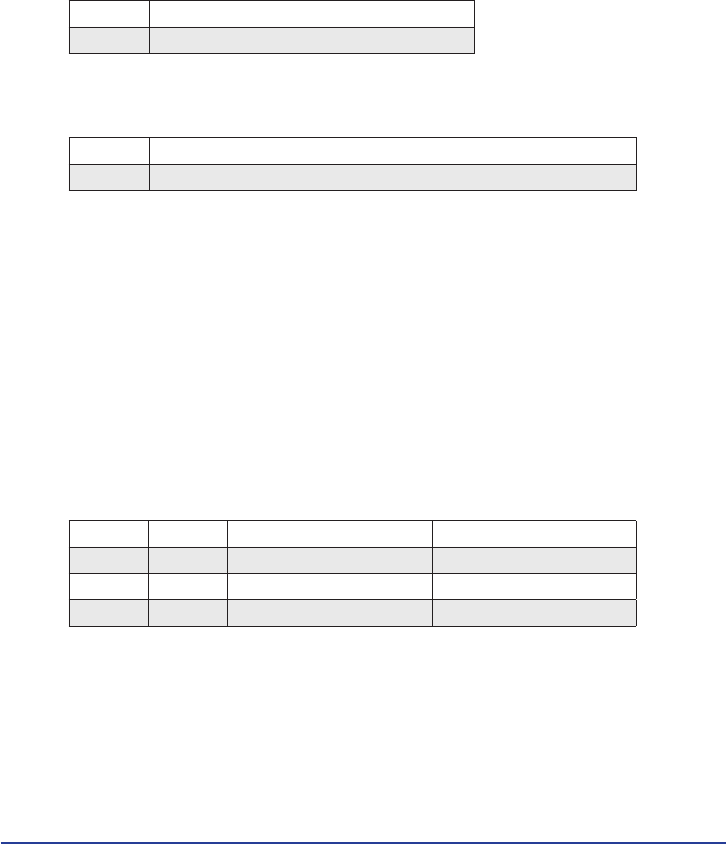
8 Technical data
Denominaon Data
Current 12-24 VDC 1,5A
Measures 130 x 73 x 25 mm
Weight 129 g
Output #11, #12
Resistancemax (Closed) 16 Ω
Blocking voltagemax 60 VDC
Load currentmax 100 mA
Leakage currentmax (Open) 1 µA
Isolaon voltage 1500V