NEC 915MSG 915MHz Wireless Transceiver Module User Manual 915M SG DataSheet
NEC Corporation 915MHz Wireless Transceiver Module 915M SG DataSheet
NEC >
User Manual
Document Number IT471-0013-X701
February 2011 (rev.1.0)
S
SS
Small size
mall size mall size
mall size 915M
915M915M
915MHz
HzHz
Hz
wireless
wireless wireless
wireless t
tt
transceiver
ransceiverransceiver
ransceiver module
module module
module
「
「「
「915M
915M915M
915M_
__
_SG
SGSG
SG」
」」
」
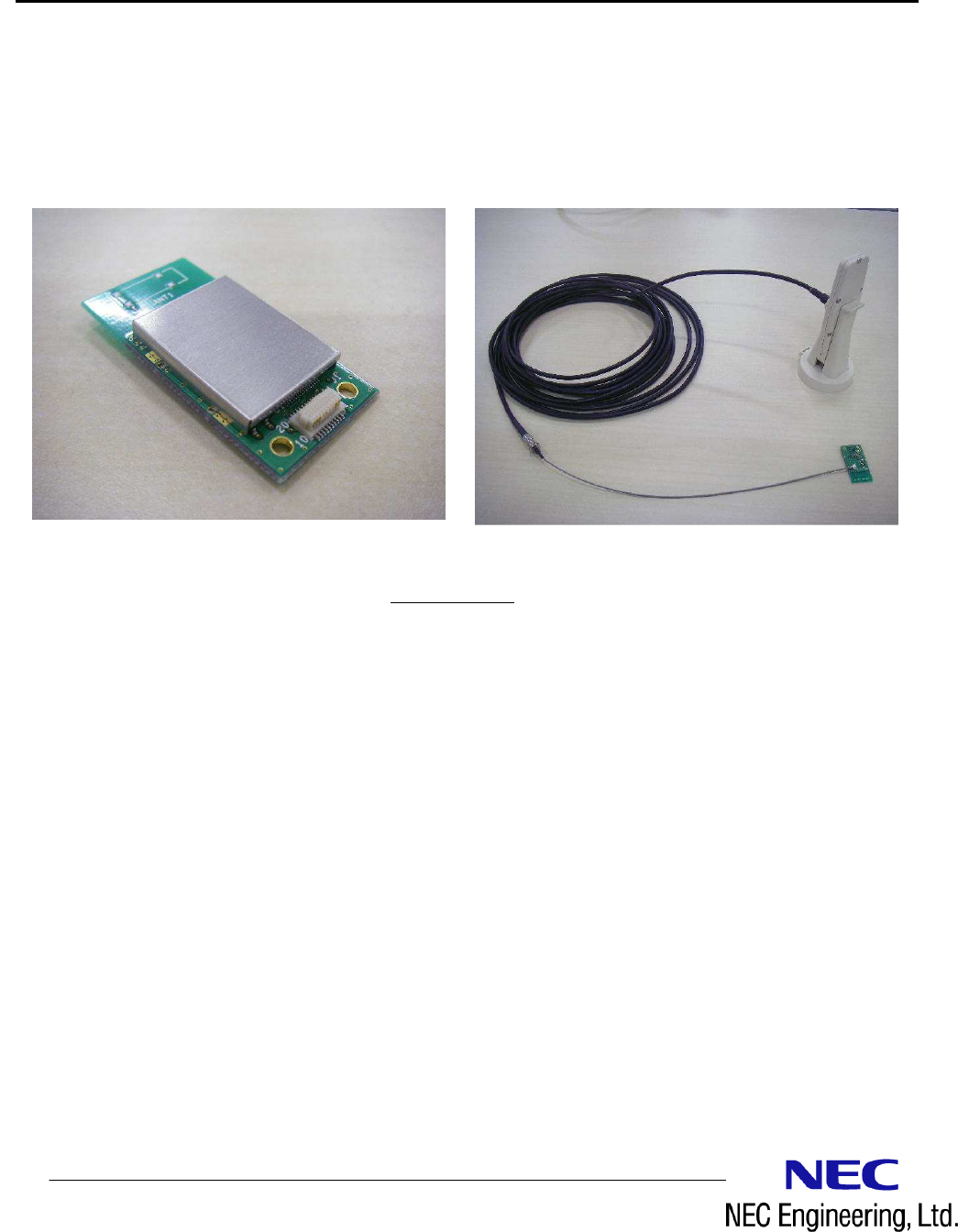
The 915M-SG is a 915MHz Low power wireless transceiver module.
Product Photo
Product PhotoProduct Photo
Product Photo
<
<<
<
Feature
FeatureFeature
Features
ss
s>
>>
>
・ Integrated by MCU, RF circuits, antenna
・ Communicated by the functions of device detect and data transmission
・ 1:1,1:N, and N:N communication style
・ Controlled by UART I/F
・ Low power sleep mode
・ DC3.0V supply voltage
・ FCC certification
Document Number IT471-0013-X701
February 2011 (rev.1.0)
<
<<
<Specification
SpecificationSpecification
Specifications
ss
s>
>>
>
Product name 915M_SG
Carrier frequency 903.5MHz~926.5MHz (24 channel)
Communication protocol Proprietary protocol
Modulation GFSK
Wireless bit rate 9.6kbps/100kbps
Transmit Power Maximum 8dBm (At the feeding point of the antenna)
Effective range About 250m (Reference value)
Interface ・UART serial communication
Data length: 8bit
Baud rate : 9.6kbs,19.2kbps,38.4kbps,57.6kbps,115.2kbps
Data length: 8bit
Parity: no parity
Stop: 1stop bit
Flow control: none
Supply Voltage ・DC +3.0±0.3V
Current Consumption ・TX: Typ. 34mA
・RX: Typ. 23mA
・Sleep Mode : Typ. 3uA
(power-supply voltage DC 3.0V)
Operating conditions ・Operating temperature range:-20℃~+75℃
・Operating humidity range:85%RH or less (No do be dewy)
Weight About 3g
Dimensions 37.3mm×18.8mm×5.2mm (D×W×H)
Restrictions
RoHS-Compliant (Pb free)
Reguration FCC certification

Document Number IT471-0013-X701
February 2011 (rev.1.0)
<
<<
<FCC statement
FCC statementFCC statement
FCC statement>
>>
>
This device complies with Part 15 of the FCC Rules. Operation is subject to the following two
conditions: (1) this device may not cause harmful interference, and (2) this device must accept any
interference received, including interference that may cause undesired operation.
Modifications not expressly approved by NEC Engineering, Ltd. could void the user's authority to
operate the equipment.
This equipment has been tested and found to comply with the limits for a Class B digital device,
pursuant to Part 15 of the FCC Rules. These limits are designed to provide reasonable protection
against harmful interference in a residential installation. This equipment generates, uses and can
radiate radio frequency energy and, if not installed and used in accordance with the instructions,
may cause harmful interference to radio communications. However, there is no guarantee that
interference will not occur in a particular installation. If this equipment does cause harmful
interference to radio or television reception, which can be determined by turning the equipment off
and on, the user is encouraged to try to correct the interference by one or more of the following
measures:
-- Reorient or relocate the receiving antenna.
-- Increase the separation between the equipment and receiver.
-- Connect the equipment into an outlet on a circuit different from that to which the receiver is
connected.
-- Consult the dealer or an experienced radio/TV technician for help.
Radiofrequency radiation exposure Information:
The radiated output power of the device is far below the FCC radio frequency exposure limits.
Nevertheless, the device shall be used in such a manner that the potential for human contact during
normal operation is minimized.

Document Number IT471-0013-X701
February 2011 (rev.1.0)
<
<<
<output
output output
output I/F
I/FI/F
I/F connector
connector connector
connector>
>>
>
connector type : Stacking connector 20pin 0.5mm pitch
product name : JST 20R-JMCS-G-TF(NSA) Receptacle
Signal level : CMOS
Customer : Recommended connector
JST 20P3.0-JMCS-G-TF(N) Plug
Stacking height 3mm
・
・・
・M
MM
Module pin definitions
odule pin definitionsodule pin definitions
odule pin definitions
P
PP
Pin
in in
in
No.
No.No.
No.
P
PP
Pin name
in namein name
in name
T
TT
Type
ypeype
ype
Definition
DefinitionDefinition
Definition
State of
State of State of
State of
reset
resetreset
reset
D
DD
Detail
etailetail
etail
1 VCC power
Power - DC3.0V(Recommended power supply voltage)
2 GND GND GND -
3 TxD OUT UART data transmit HiZ
4 RxD IN UART data receive HiZ
5 WAKEUP
IN WAKEUP input HiZ Sleep mode enable = High /disable = Low input
Internal Pullup
6 RESET IN RESET input HiZ RESET Low input
Internal Pullup
7 GPIO1 - Reserve - n.c
8 TSI IN TSI input HiZ internal Pullup
9 TSO OUT TSO output HiZ
10
GPIO4 - Reserve - n.c
11
VCC power
power - DC3.0V(Recommend power supply voltage)
12
GND GND GND -
13
GND GND GND -
14
CTS - Reserve n.c
15
P_STATE
OUT Mode output Normal mode = Low / sleep mode =High output
16
FLMD0 - TEST Pin - n.c
17
TOOL0 - TEST Pin - n.c
18
TOOL1 - TEST Pin - n.c
19
RTS - Reserve n.c
20
GND GND GND -
Document Number IT471-0013-X701
February 2011 (rev.1.0)
<
<<
<RF
RFRF
RF connector
connector connector
connector>
>>
>
RF Connector connects with antenna through cable.
connector type : Ultra small surface mount coaxial connector
product name : Hirose Electronic U.FL-R-SMT-1
impedance : 50Ω
<
<<
<a
aa
antenna
ntennantenna
ntenna and cable for antenna connection
and cable for antenna connection and cable for antenna connection
and cable for antenna connection>
>>
>
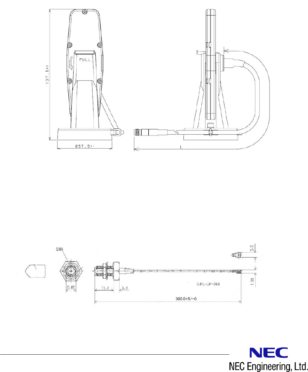
・antenna
product name : MIDORI ANZEN NMA-01
impedance : 50Ω
antenna gain : less than 3dBi
Unit:mm
・cable for antenna connection
product name : Hirose Electronic HRMBPJ-U.FL-04N1-A-100RS
impedance : 50Ω
cable length : 300mm
Unit:mm
Document Number IT471-0013-X701
February 2011 (rev.1.0)
<
<<
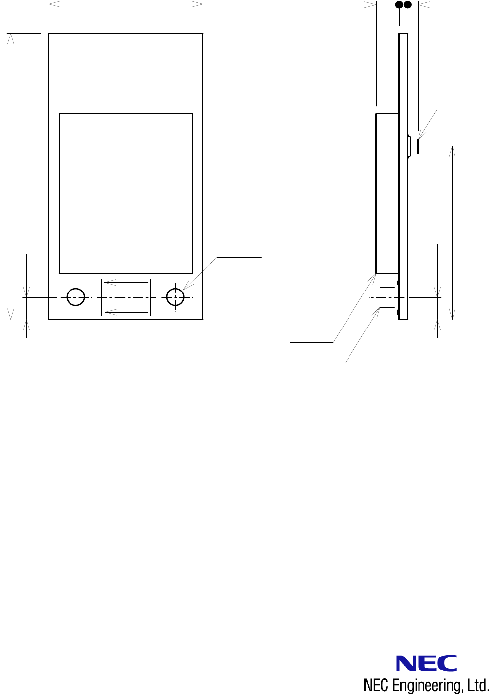
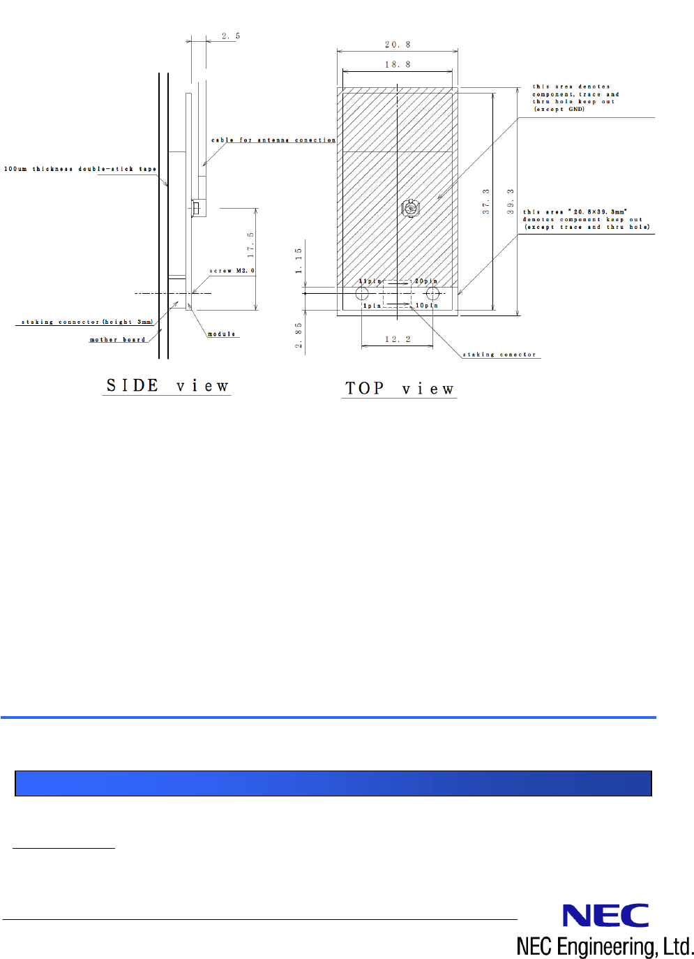
<Dimensions
DimensionsDimensions
Dimensions>
>>
>
unit:mm
Side view Top view
Staking hight 3mm
20pin Staking connector
cap
RF connector
Document Number IT471-0013-X701
February 2011 (rev.1.0)
<
<<
<Installation
InstallationInstallation
Installation>
>>
>
NEC Engineering,Ltd.
General inquiries
Sales&Marketing Division
4-10-27 Higashishinagawa Shinagawa-ku Tokyo 140-0002 Japan
TEL:
+81 3 6713 1200 URL http://www.nec-eng.com/
Contact