NEC FC-N21S Computer FC-NOTE Series User Manual FC N21S
NEC Corporation Computer FC-NOTE Series FC N21S
UserManual.wiki
>
NEC
>
FC-N21S User Manual
>
User Manual 1
Contents
1.
User Manual 1
2.
User Manual 2
3.
User Manual 3
User Manual 1
Navigation menu
Upload a User Manual
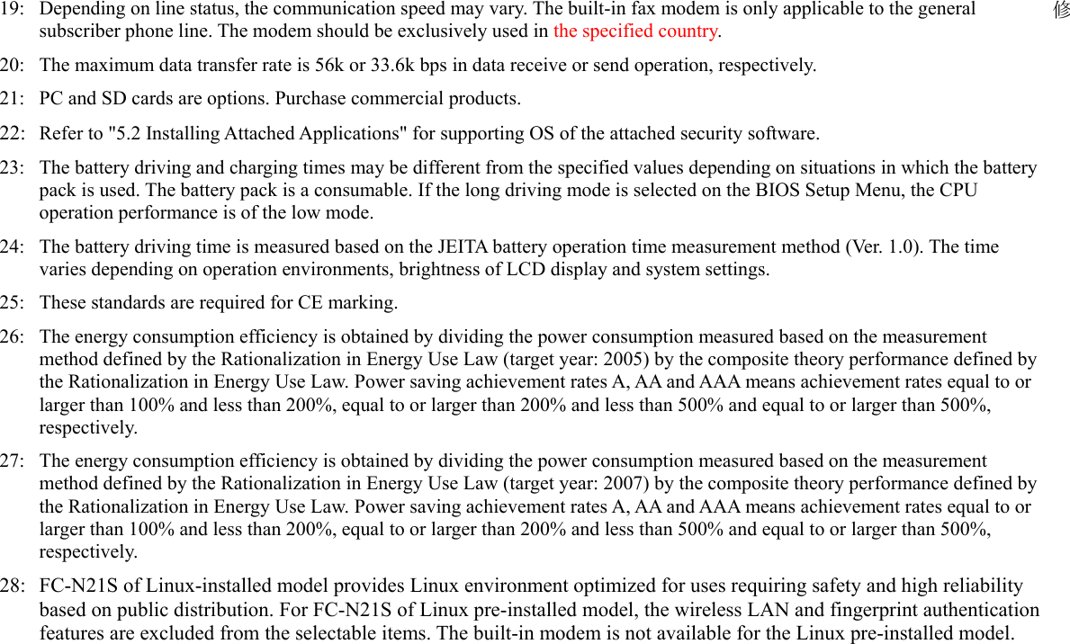
Namespaces
Wiki Guide
HTML
PDF
Info
Views
User Manual
Discussion / Help
Navigation

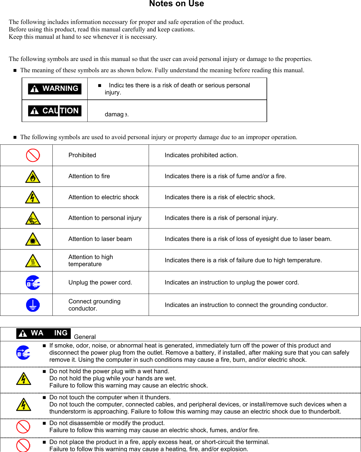

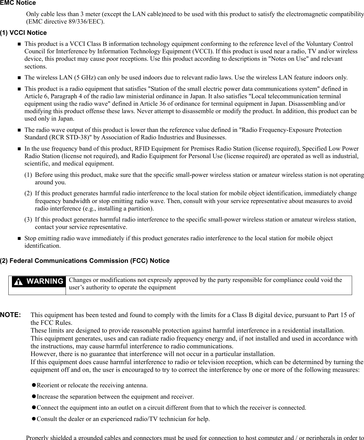
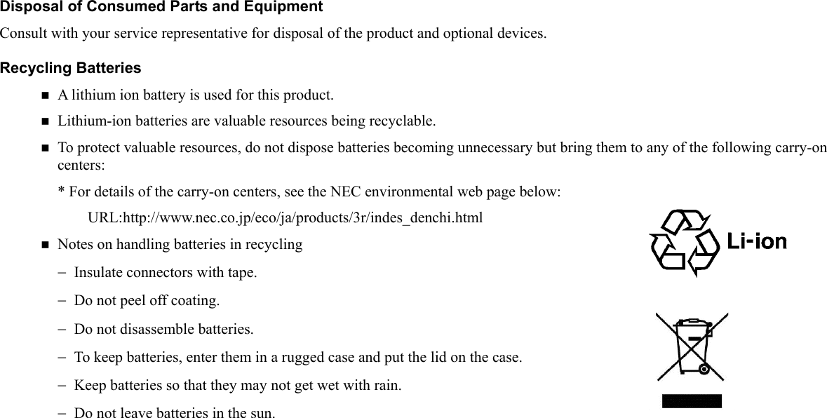

![Chapter 1 System Overview This chapter overviews FC-N21S, the FC-NOTE Series ShieldPRO System. 1.1 HARDWARE SPECIFICATION Item FC-N21S (Note 1) CPU (Note 2) Intel Core Solo U1400 ultra-low voltage processor (Extended Intel SpeedStep technology (Note 3) installed [1.20 GHz]) Primary 32KB for instruction/32KB for data (built in CPU) Cache memory Secondary 2.048KB (built in CPU) System bus 533 MHz (memory bus: 400 MHz) Chip set Mobile Intel 945GM Express chip set ICH7-M Security chip (Note 4) Conforming to TPM V.1.2 Memory (Note 5) 2GB max. (Note 6) 2 SO-DIMM slots DDR2-SDRAM (PC2-3200 (DDR2-400)) 12.1-in. TFT color LCD display (XGA) with touch panel (Note 8) Display element (Note 7) Stuck pixels of LCD (Note 9) 0.0005% or less Graphic accelerator Built in mobile Intel 945GM Express chip set (Dual display (Note 10), smoothing, and screen rotation features available) Video RAM 128MB max. (use of main memory) Display feature Resolution and display colors LCD: 1024×768 dots (16.77 million colors (Note 11)) External monitor: 1600×1200 dots max. (Note 12) (16.77 million colors (Note 11)) Floppy disk drive [Option] FC-FD002U connectable (USB connection) CD-ROM type drive [Option] FC-CW002U connectable (USB connection) Fixed disk drive (Note 14) [Selectable item] 60GB (Serial ATA specification) or 40GB (wide temperature range and Ultra ATA specification) Auxiliary storage (Note 13) Silicon disk drive (Note 14) [Selectable item] 8GB (Ultra ATA specification) Keyboard (Note 15) [Selectable item] Standard or backlight keyboard (with or without keyboard cover selectable) English keyboard Key pitch: 17.55 mm Key stroke: 2.4 mm(backlight keyboard : 2.0mm) Pointing device Touch pad Input device Tablet button 10 (5 buttons and 5 Tb + buttons) (Note 16) USB (Note 17) 3 ports (including 1 connect/disconnect-proof enhanced port), USB2.0 compatible Serial 1 D-sub 9-pin connector of 115,200 bps max. (male) Display Mini D-sub 15-pin connector (female) (for analog RGB monitor) Built-in LAN 1 RJ45 (1000BASE-T / 100BASE-TX / 10BASE-T) LAN connector Network Wireless LAN [Selectable item] Conforming to IEEE802.11a/b/g (Note 18) WEP [encryption key length: 64/128 bits (user setting key length: 40/104 bits)], WPA-PSK (TKIP/AES) and WPA2-PSK (AES) compatible Built-in modem (Note 19) 1 RJ11 modular connector Modem: 56k bps max. (Note 20) (V.90/V.92 compatible) FAX: 14.4k bps max. (V.17 compatible) Interface (Note 13) Sound feature Built-in PCM record/replay feature and monaural speaker Microphone input (stereo, mini jack) and output common to headphone/line (stereo, mini jack) PCcardslot(Notes13and21)1TypeI/IIslot (Type III unavailable) conforming toPCCard Standard and compatible](https://usermanual.wiki/NEC/FC-N21S.User-Manual-1/User-Guide-865915-Page-17.png)
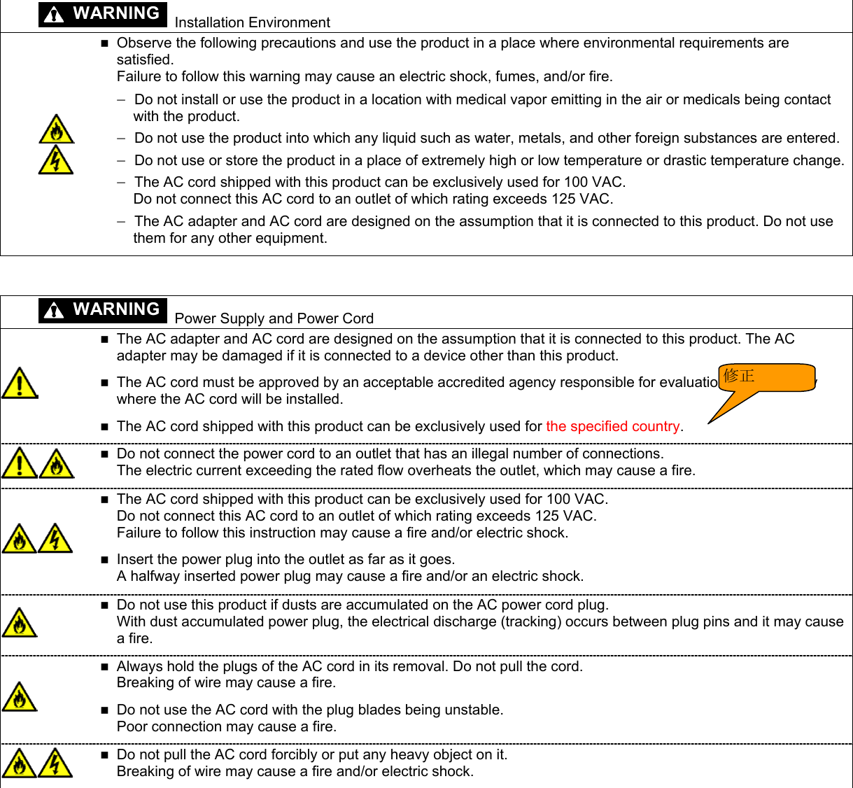
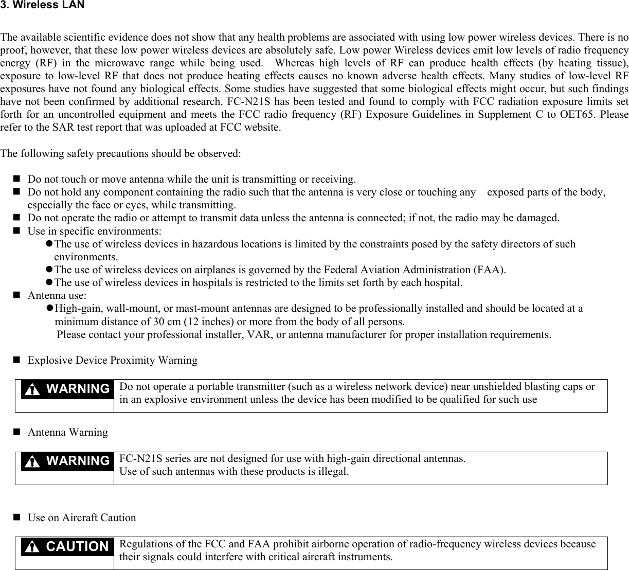
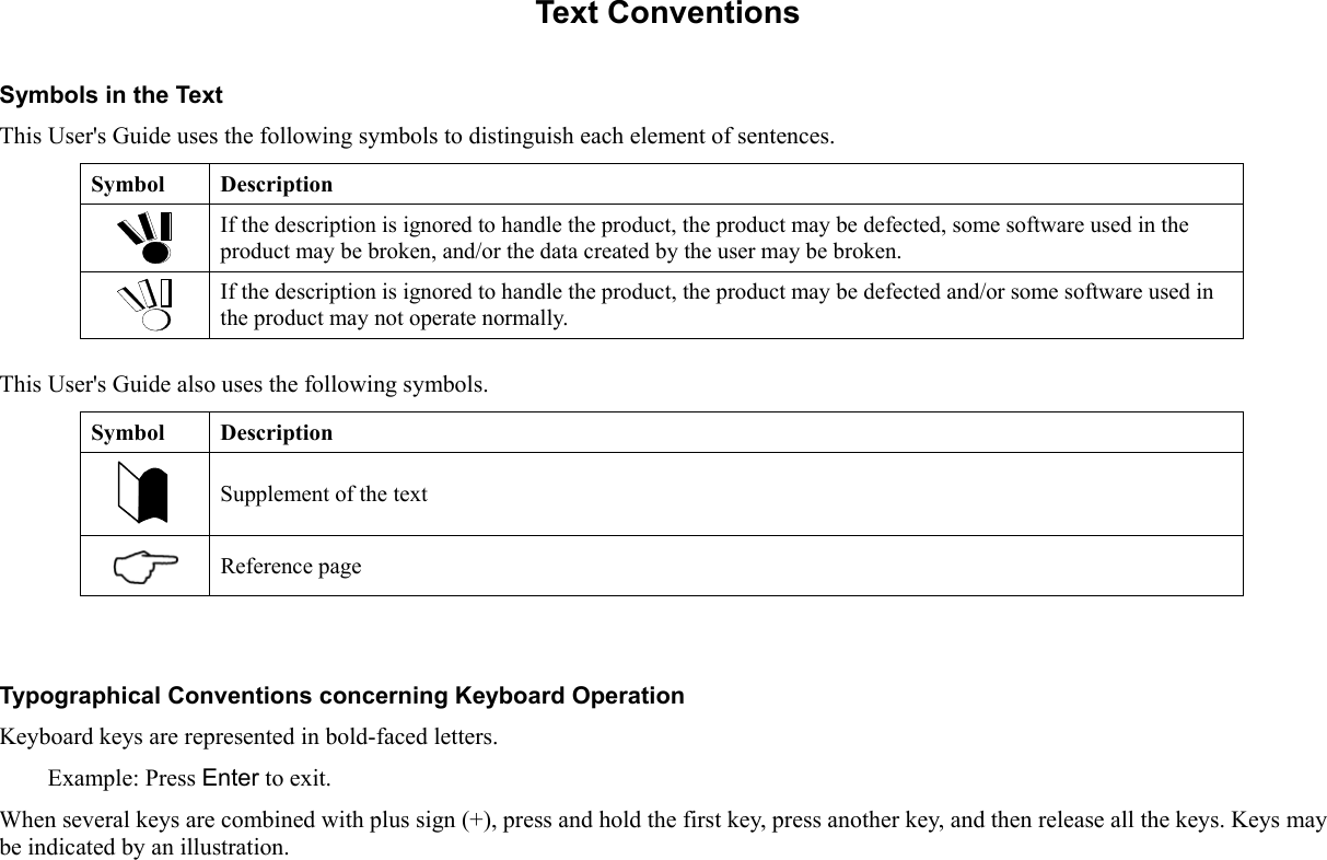
![Item FC-N21S (Note 1) This machine Operating voltage: 16 V±5% Battery (Notes 23 and 24) [Selectable item] Standard type: driving period - 8 hours, charging time (in power-on/off states) - about 3 hours/3 hours and weight: 0.3 kg Power supply AC adapter 100 to 240 VAC ±10%, 50/60 Hz [Do not use the specified AC adapter and AC Code.] Conforming standard Suitable to RoHS direct and conforming to VCCI Class B. Designed based on EMC direct (EN55022 and EN61000-6-2) (Note 25) and low voltage direct (EN60950-1) (Note 25) standards. Power design based on standard UL60950-1 Power consumption About 15 W (about 50 W max.) Energy efficiency (Power saving achievement rate) Target year: 2005 (Note 26), S division 0.00025 (AAA) Target year: 2007 (Note 27), I division 0.0020 (A) Outside dimension 284(W) × 255(D) × 48(H) mm (excluding projections and bumper) Weight About 2.5 kg (including standard battery) Installed OS [Selectable item] Microsoft Windows XP Professional (Service Pack 2) Japanese / English or Linux (Note 28) Notes: 1: See "1.2 Selection Menu Table" for type names and numbers. 2: FC-N21S includes a control feature enabling the CPU to operate dynamically depending on use environments and loads. 3: In any OS environment other than preinstalled OS environment, the expanded IntelSpeedStep feature may be unavailable. 4: The security chip is unavailable to any OS other than preinstalled Windows XP Professional. 5: The capacity of a memory board can be selected out of 256MB, 512MB, 1GB and 2GB on the selection menu. Expanded RAM boards FC-UG-M011 (256MB, PC2-4200), FC-UG-M012 (512MB, PC2-4200) and FC-UG-M013 (1GB, PC2-4200) are available. 6: Replacement of an expanded RAM board is enabled only on a single slot. The maximum memory capacity can be installed if memory of 1GB or larger is selected. If memory of less than 1GB is selected, the maximum memory capacity is "selected memory capacity" + 1GB. 7: The LCD display is manufactured based on extremely high-precise technology. However, dot drops (such as negligible black points and red, blue or green points always illuminating) may appear on a part of the screen. In addition, color and/or brightness irregularities may appear depending on view angles. These are caused by characteristics of LCD displays and do not indicate any defects. 8: The touch panel is unavailable under USB locking. 9: The base dot drop rate is calculated in sub-pixels according to the standard of ISO13406-2. See http://www.express.nec.co.jp/products/pc/lcddot.html for details. 10: The feature allows an external display for desktop screen to be different from the LCD display of FC-N21S. 11: 16.77 million color display is accomplished by the dithering feature of graphic accelerator. 12: FC-N21S has the resolution and the number of colors. However, FC-N21S cannot realize them depending on the resolution and refresh rate of the connected display. The LCD display on FC-N21S and the external display connected to FC-N21S can display the same screen. However, if the enlarged display feature is not used, display data may not extend to all over the external display. 13: Before a commercial product can be used for FC-N21S, you should previously evaluate the product to confirm that the product is valid. 14: Fixed and silicon disk drives should be installed exclusively with each other. 15: The standard English keyboard is only selectable for the Windows XP Professional (Service Pack 2) pre-installed model. 16: Each tablet button can be set to have the feature of starting any application. fiihldbfi h i f修](https://usermanual.wiki/NEC/FC-N21S.User-Manual-1/User-Guide-865915-Page-18.png)
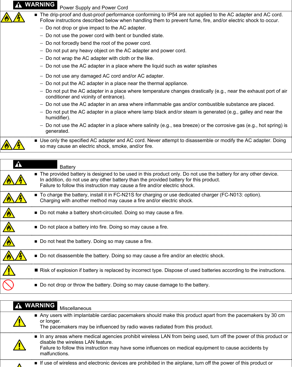
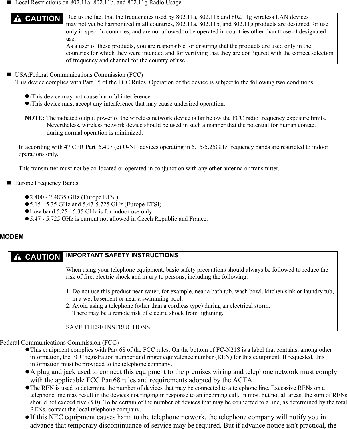
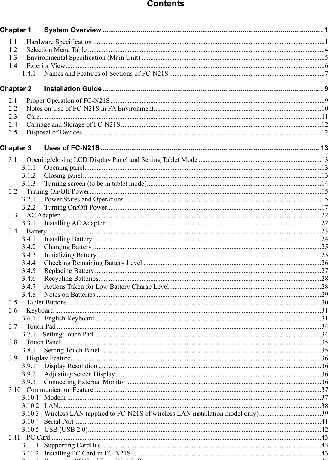
![1.2 SELECTION MENU TABLE Series title Selection menu Base unit Keyboard OS Memory capacity Disk drive and battery Wireless LAN andfingerprint authentication [2] 256MB (256MB × 1) [S] Wireless LAN: Yes Fingerprint authentication: No (Note 2) [Y] Windows XP Professional (Service Pack2) English ver. preinstalled (Note 1) [3] 512MB (512MB × 1) [4] 1GB (1GB × 1) [5] 2GB (1GB × 2) [S] Standard HDD (SerialATA spec., 60GB) Standard battery [Z] Wireless LAN: No Fingerprint authentication: No FC-N21S CPU Intel Core Solo Processor Ultra-low voltage ver. U1400 (1.2 GHz) Memory (2 slots) PC card (1 slot) SD card (1 slot) [B] Standard keyboard [L] Linux preinstalled (Note 2) [C] or [0] Custom No. [X] Serial Number from “0” to “9” or from “A” to “Z” [X] Serial Number from “0” to “9” or from “A” to “Z” Part name Model name Part number Notes: 1: The key assignments are based on the standard English keyboard layout. 2: For FC-N21S of Linux pre-installed model, the wireless LAN and fingerprint authentication features are excluded from the selectable items. The built-in modem is not available for the Linux pre-installed model. * The part and generation numbers of FC-N21S are directed on the nameplate and warranty at shipment. See the NEC web site for details of the generation numbers. Ex.: For order number FC-N21S/BX2SS, the notation on the nameplate and warranty is FC-N21S/BX2SS** (**: generation number). * FC-N21S of Windows XP pre-installed model already has Microsoft Windows XP Professional Operating System (Service Pack 2) installed. Note that deleting and down-grading of Service Pack is disabled. First partition: 20GB (NTFS) (Software already installed at shipment occupies about 5GB in the first partition.) Second partition: Remaining memory (NTFS) * For FC-N21S of Linux pre-installed model, the distributed Linux is MIRACLE LINUX 4.0 kernel 2.6. Contact NEC for other distributed Linux. First partition: 20GB (ext3) (Software already installed at shipment occupies about 4GB in the first partition.) Second partition: 1GB (ext3) Remaining partition: Not formatted](https://usermanual.wiki/NEC/FC-N21S.User-Manual-1/User-Guide-865915-Page-20.png)
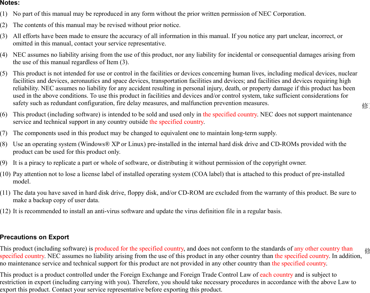
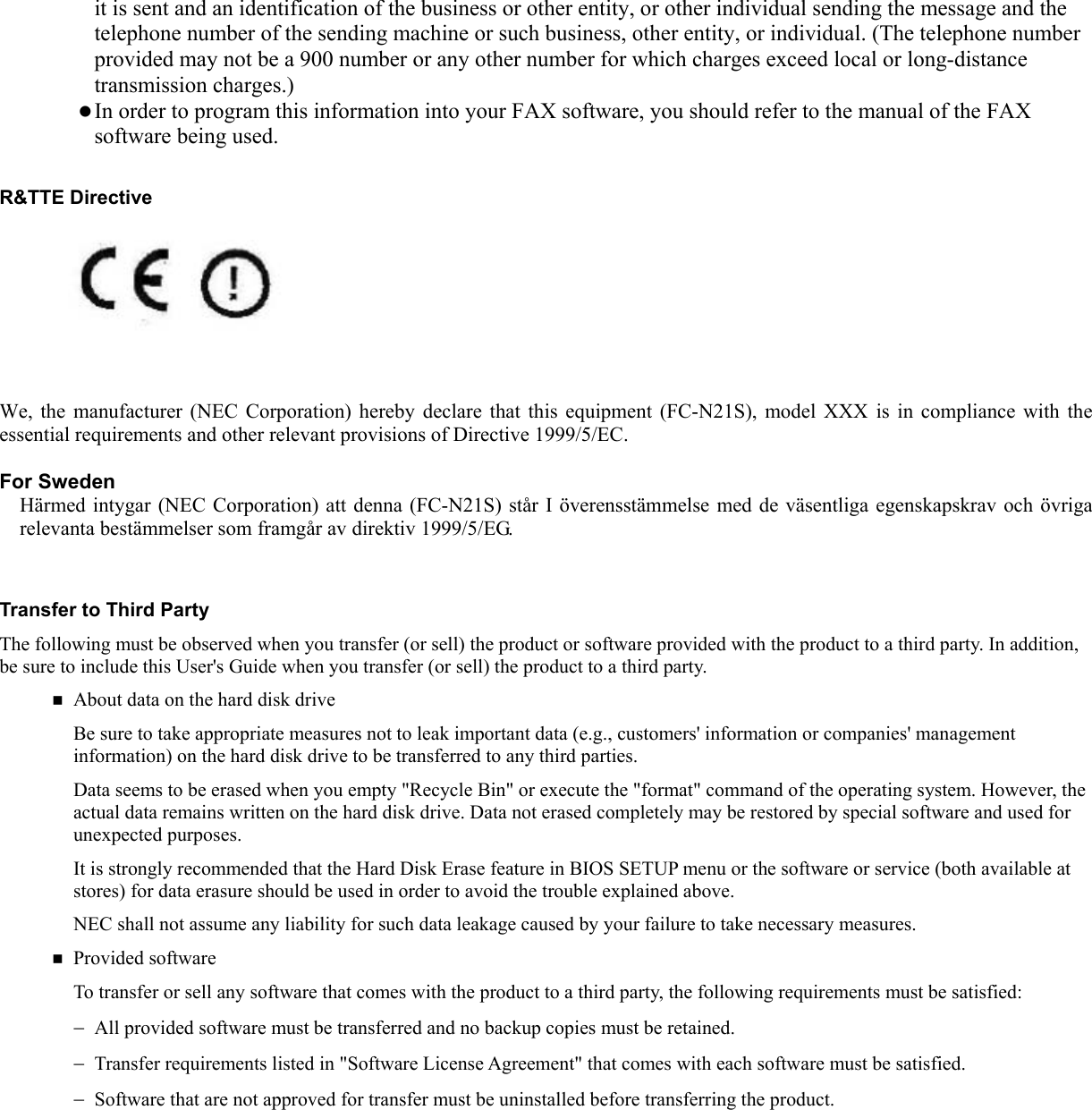
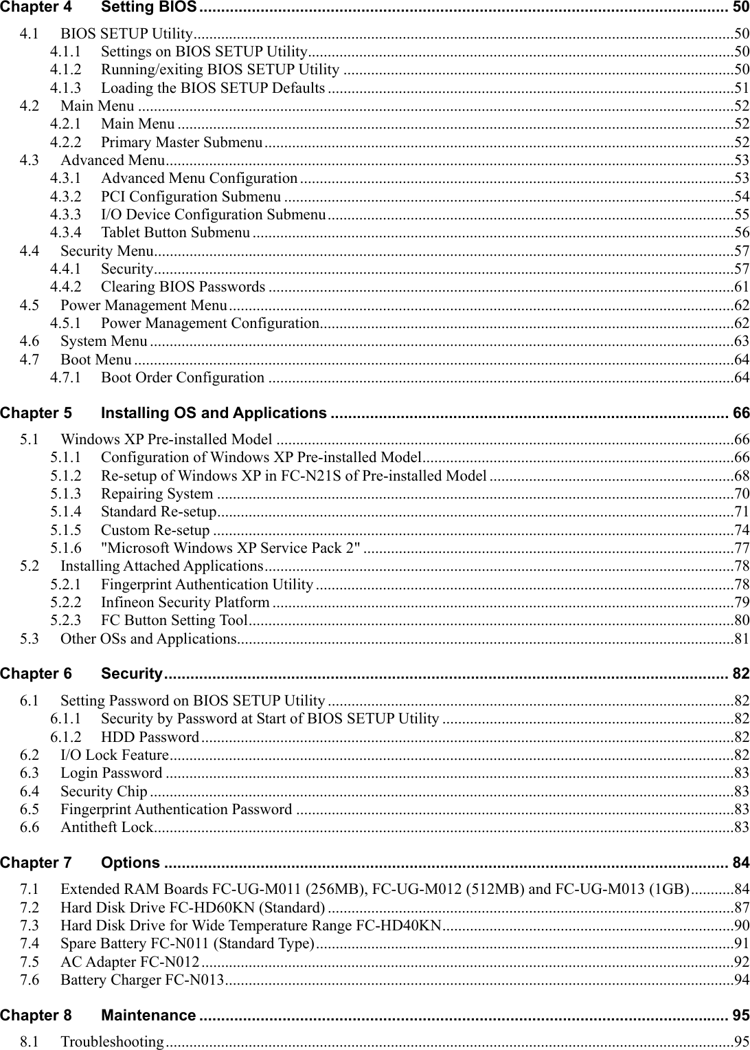
![1.3 ENVIRONMENTAL SPECIFICATION (MAIN UNIT) Condition Item Installation of standard hard disk drive and battery Operating 5 to 45 ºC Storage -40 to 70ºC Temperature Evaluation standard IEC 68-2-1,2,14 / MIL-STD-810F, Method 501.4, 502.4 Operating 5 to 95% RH (without condensation) Storage 5 to 95% RH (without condensation) Humidity Evaluation standard IEC 68-2-30 / MIL-STD-810F, Method 507.4 Operating 15,000 ft (4,57 2m) Storage 40,000 ft (12,190 m) Change rate 2,000 ft/min (609.6 m/min) Altitude Evaluation standard IEC 68-2-13 / MIL-STD-810F, Method 500.4 Operating 147 m/s2, 11 ms, half sinusoidal wave Storage 490 m/s2, 11 ms, half sinusoidal wave Shock resistance (Note 1) Evaluation standard IEC 68-2-27 / MIL-STD-810F, Method 516.5 Operating [Sinusoidal wave] 0.075 mm (0-P) in frequency range 10 to 55 Hz 9.8 m/s2 (0-P) in frequency range 55 to 500 Hz Storage [Sinusoidal wave] 0.15 mm (0-P) in frequency range 10 to 55 Hz 19.6 m/s2 (0-P) in frequency range 55 to 500 Hz [Random wave] 0.04G2/Hz in frequency range 20 to 1000 Hz –6 dB/Octave in frequency range 1000 to 2000 Hz Operating Sinusoidal wave: IEC68-2-6 Vibration resistance (Note 1) Evaluation standard Storage Sinusoidal wave: IEC68-2-6 Random wave: MIL-STD-810F, Method 514.5 Category 24 FIGURE 514.5C-17 Operating IP54 Storage IP54 Dust proof and drip proof Evaluation standard IEC 529 / MIL-STD-810F IEC: Abbreviation for International Electrotechnical Commission. MIL: Abbreviation for Military Specifications and Standards. Note 1: The vibration resistance of FC-N21S does not assure that it has sufficient strength against resonance generated when the frequency of added vibration is close to the natural frequency of FC-N21S. * The specification does not assure that FC-N21S can operate continuously under the described environmental conditions in which FC-N21S is installed. In addition, if FC-N21S is equipped with one or more NEC or commercial options, the most severe environmental condition among those for FC-N21S and the options is applied. While FC-N21S is stored in a place at ambient temperature of 0ºC or lower, the clock built in FC-N21S may be shifted. Set the clock before FC-N21S is used again.](https://usermanual.wiki/NEC/FC-N21S.User-Manual-1/User-Guide-865915-Page-21.png)
![(2) Outside sections No. Name Description Reference page (1) Power terminal Connects with the AC adapter. 22 (2) Mike terminal (stereo) Connects with a commercial microphone (stereo and mini jack type) 46 (3) Output terminal common to line and headphone (stereo) Outputs sounds to a commercial audio device or headphone (stereo and mini jack type) 46 (4) Antitheft lock Connects with a commercial security cable. 83 (5) External monitor output connector Connects with an external analog RGB monitor. 36 (6) Serial connector Connects with a serial device such as a modem. 41 (7) LCD display fixing lock Locks the LCD display. 13 (8) Touch pen storage area Stores the attached touch pen. - (9) Battery storage area Stores the attached battery. 23 (10) Disk drive storage area Stores disk drives (installed). 87 (11) Expanded memory storage area Stores expanded RAM board of an option. 84 (12) Built-in speaker (monaural) Monaural speaker for sound replay. 46 (13) USB connector (1) (Connect/disconnect-proof enhanced type) Connects with a USB device (USB2.0 available). 42 (14) USB connector (2) Connects with a USB device (USB2.0 available). 42 (15) USB connector (3) Connects with a USB device (USB2.0 available). 42 (16) SD card slot Accepts an SD card. 44 (17) PC card slot Connects with a PC card (PCMCIA of type II) for feature expansion. 43 (18) Modular connector for phone line Connects with phone line. 37 (19) LAN (1000BASE-T) connector Connects with LAN (1000BASET/100BASETX/10BASET)cable38(1) [Rear view] [Front view] [Bottom view] (2) (3) (4) (5) (6)(8) (9)(10)[Left side view] [Right side view] (11) (12)(17) (18) (19)(13) (14) (15) (16) (7)](https://usermanual.wiki/NEC/FC-N21S.User-Manual-1/User-Guide-865915-Page-24.png)
![3.2.1.2 Operating power supply The power supply of FC-N21S is mainly operated as follows. 1. Turning on power (in either of the following two ways) Press the power switch. Connect the AC cable to FC-N21S (if "power state at AC power-on" of BIOS is set to "ON") WARNING Do not use this product if dusts are accumulated on the AC power cord plug. With dust accumulated power plug, the electrical discharge (tracking) occurs between plug pins and it may cause a fire. Always hold the plugs of the AC cord in its removal. Do not pull the cord. Breaking of wire may cause a fire. Do not pull the AC cord forcibly or put any heavy object on it. Breaking of wire may cause a fire and/or electric shock. Use only the specified AC adapter and AC cord. Never attempt to disassemble or modify the AC adapter. Doing so may cause an electric shock, smoke, and/or fire. For the power lock release switch, see "Chapter 4 Setting BIOS". Press the power switch continuously for 1 second or longer. To avoid improper operations, FC-N21S is so designed that the power is turned on only by pressing the power switch for 1 to 2 sec consciously. If FC-N21S is activated only by the battery, it takes 1 to 2 sec to turn on LEDs after depression of the power switch. This is because FC-N21S is so designed as to prevent battery power from being consumed by turning off all powers including the standby power in the power-off state. This does not occur in use of "WakeOnLAN", since the standby power remains to sense LAN signals. 2. Turning off power (in either of the following two ways) Press the power switch. Select [Turn Off Computer] in the Windows Start menu and click [Turn off]. 3. Entering FC-N21S into suspend (standby) state (in any of the following three ways) Select [Standby] in the Windows Start menu and click [Standby]. Press the power switch (if OS setting is changed to allow this operation). Close the LCD display panel (if OS setting is changed to allow this operation). Some OSs cannot enter FC-N21S into the suspend (standby) and/or pause states. It may take some time to enter FC-N21S into the suspend (standby) state after the LCD display panel is closed. FC-N21S may not enter into the suspend (standby) state if the LCD display panel is closed only for a short period. If so, close the LCD display panel again. 4. Resume FC-N21S (recover FC-N21S from the suspend (standby) state (in either of the following two ways). Press the power switch. Open the LCD display panel. Some OSs cannot enter FC-N21S into the suspend (standby) state. Opening the LCD display panel during transition to the suspend (standby) state cannot recover FC-N21S from the suspend (standby) state. If so, close the LCD display panel once after FC-N21S is entered into the suspend (standby) state. Then open the LCD display panel.](https://usermanual.wiki/NEC/FC-N21S.User-Manual-1/User-Guide-865915-Page-32.png)
![3.2.2 Turning On/Off Power 3.2.2.1 Turning on power To turn on the power in the power-off state, be sure to follow the procedure described below. To turn on the power again, wait for five seconds or longer after power-off. 1. Turn off the peripheral devices. Some peripheral devices may be recognized properly only when their powers are turned on before turning on the power of FC-N21S. Refer to the User’s Guides of peripheral devices previously. 2. Press the power switch of FC-N21S. Power lock release switch Power switch For memory initialization, it may take some time to allow the initial screen to appear after power-on. For the power lock release switch, see "Chapter 4 Setting BIOS". Press the power switch continuously for 1 sec or longer. To avoid operation mistakes, FC-N21S is so designed that the power is turned on only by pressing the power switch for 1 to 2 sec consciously. If FC-N21S is activated only by battery, it takes 1 to 2 sec to turn on LEDs after depression of the power switch. This is because FC-N21S is so designed as to prevent battery power from being consumed by turning off all powers including the standby power in the power-off state. This does not occur in use of "WakeOnLAN", since the standby power remains to sense LAN signals. 3.2.2.2 Turning off power To turn off the power of FC-N21S, follow either of the procedures below. After power-on, do not turn off the power while Windows and one or more applications are activated. Before turning off the power, confirm that neither the mouse pointer nor the sand clock appear and the file access LED does not illuminate. (1) Power-off procedure by using Windows End menu 1. Save edited data and quit all the applications. 2. Perform the following operation. For Windows XP: Click [Start] → [Turn Off Computer]. Then click [Turn Off]. The power of FC-N21S is automatically turned off by software. Do not press the power switch during the shutdown processing. 3. After confirming that the power of FC-N21S is turned off, turn off the peripheral devices. (2) Power-off procedure by using power switch 1. Save edited data and quit all the applications. 2. Press the power switch.](https://usermanual.wiki/NEC/FC-N21S.User-Manual-1/User-Guide-865915-Page-33.png)
![3.2.2.3 Suspend (standby)/resume If you want to suspend jobs on FC-N21S temporarily, you can enter FC-N21S into the suspend (standby) state to save power consumption. To suspend (standby) and then resume FC-N21S with the power switch, the setting of the power switch must be changed. Click [Control Panel] → [Performance and Maintenance] → [Power Options]. Click the [Advanced] tab on the [Power Options Properties] dialog box and select [Standby] in field [When I press the power button on my computer:]. Click [Control Panel] → [Performance and Maintenance] → [Power Options]. Click the [Advanced] tab on the [Power Options Properties] dialog box and select [When I close the lid of my portable computer:] in the [Standby] field. Before you can suspend (standby) and then resume FC-N21S, wait for five seconds or longer after change of the power lamp status. To enter FC-N21S into the suspend (standby) state in the power-on state manually, follow either of the procedures below. (1) Procedure by using power switch 1. Entering FC-N21S into suspend (standby) state Press the power switch in the power-on state. The power lamp blinks in green and FC-N21S is set to the suspend (standby) state. 2. Resuming FC-N21S (recovering FC-N21S from suspend (standby) state) Press the power switch in the suspend (standby) state. The power lamp illuminates in green and FC-N21S recovers from the suspend (standby) state (or resumes). Do not press the power switch for four seconds or longer to suspend (standby) or resume FC-N21S. Pressing the power switch for four seconds or longer causes the power to be turned off forcibly, which results in erasing of unsaved data. (2) Procedure by opening/closing LCD display panel 1. Entering FC-N21S into suspend (standby) state Close the LCD display panel in the power-on state. The power lamp blinks in green and FC-N21S enters into the suspend (standby) state. 2. Resuming FC-N21S (recovering FC-N21S from suspend (standby) state Open the LCD display panel in the suspend (standby) state. The power lamp illuminates in green and FC-N21S recovers from the suspend (standby) state (or resumes).](https://usermanual.wiki/NEC/FC-N21S.User-Manual-1/User-Guide-865915-Page-34.png)
![3.2.2.4 Pause state and recovering from pause state If jobs on FC-N21S are halted for a long period, entering FC-N21S into the pause state allows power consumption to be saved. To enter or recover FC-N21S into or from the pause state by using the power switch, you must change the setting in the [Power Options] dialog. Click [Start] → [Control Panel] → [Performance and Maintenance] → [Power Options]. Click the [Hibernate] tab on the [Power Options Properties] dialog box and check [Enable hibernation]. (1) Entering power into pause state To enter FC-N21S into the pause state in the power-on state manually, follow either of the following ways. Procedure by using Windows Exit menu 1. Click [Start] → [Turn Off Computer]. 2. Perform the operation below. For Windows XP: Click [Start] → [Turn Off Computer]. Then press Shift and click [Hibernate]. Procedure by using power switch 1. Press the power switch. The working conditions are saved in the hard disk drive. The power is turned off and FC-N21S is entered into the pause state. Do not press the power switch for four seconds or longer to enter FC-N21S into the pause state. Pressing the power switch for four seconds or longer causes the power to be turned off forcibly, which results in erasing of unsaved data. (2) Recovering power-on state from pause state To recover the power-on state from the pause state manually, follow the procedure below. 1. Press the power switch. Windows is started to recover the state set when the power was turned off last by using the pause state feature. (3) Notes on use of pause state feature To use the pause state feature, note the following. Failure to follow the notes may cause working data for entering FC-N21S into the suspend (standby) state to be lost and/or FC-N21S not to be resumed. 1. No assurance of recovering from pause state Any of the following actions during storage of working data in transition to or recovery from the pause state cannot assure the working data: Changing configuration of peripheral devices (installing/removing a peripheral device) Removing or replacing floppy disk or CD-ROM In addition, if FC-N21S is entered into the pause state under any of the following situations, working data is not assured: Performing system change job (including setting driver or adding printer), Outputting data to printer, Replaying audio or motion pictures, Reading/writing data from/to SD card or hard disk, Reading/writing data from/to floppy disk, CD-R or DVD-R, Using application not applicable to the pause state feature, Using peripheral device or expanded board not applicable to the pause state feature, Executing Windows start or exit processing Connectingwithnetworkthrough fax modem or LAN by communication software](https://usermanual.wiki/NEC/FC-N21S.User-Manual-1/User-Guide-865915-Page-36.png)