NEC FC-N21S Computer FC-NOTE Series User Manual FC N21S
NEC Corporation Computer FC-NOTE Series FC N21S
NEC >
Contents
- 1. User Manual 1
- 2. User Manual 2
- 3. User Manual 3
User Manual 3
(This page is intentionally left blank.)
Chapter 5 Installing OS and Applications
5.1 WINDOWS XP PRE-INSTALLED MODEL
5.1.1 Configuration of Windows XP Pre-installed Model
FC-N21S of Windows XP pre-installed model has Microsoft Windows XP Professional installed at factory shipment to be automatically
booted at power-on.
The parameters are previously set to the factory defaults as shown in the table below. Accordingly, you may not enter them on booting of
FC-N21S.
Parameter Factory default
Owner FC-USER
Organization (Not set)
Computer name FCN21S-XXXXX
Value "XXXXX" in the computer name shows the lowest five digits of the product ID of Microsoft Windows XP Professional. For the
product ID, see the Microsoft Windows XP Professional license label pasted on the bottom of FC-N21S.
For how to change the computer name, see "Specify computer and workgroup names" in the Online Help of Microsoft Windows XP
Professional.
To change the owner or organization, see next subsection "5.1.1.1 Changing Owner and/or Organization by Modifying Registry" or provide
re-setup for Windows XP. For the re-setup, see "l5.1.2 Re-setup of Windows XP in FC-N21S of Pre-installed Model".
For the HDD installed in FC-N21S of pre-installed model, the first and second partitions (or system and remaining areas respectively) are
formatted at shipment from factory.
To change the format so as to assign the second partition (remaining area) to more than one drive, select [Start] → [Control Panel] →
[Performance and Maintenance] → [Administrative Tools] → [Computer Management] → [Disk Management] after the setup is
completed.
Capacity (1st HDD)
First partition Second partition
20GB (NTFS) Standard HDD: About 40GB (NTFS)
Wide temperature range HDD: About 20GB (NTFS)
Note that Windows XP installed in FC-N21S is not specified as an upgrading/downgrading product by
Microsoft.

5.1.1.1 Changing Owner and/or Organization by Modifying Registry
The registry has a variety of information required to operate Windows XP.
Changing the registry incorrectly may cause Windows XP to be started improperly. Change the registry with
sufficient care.
If Windows XP is not started or started improperly after change of the registry, reinstall Windows XP.
Be sure to change the registry before installing applications in FC-N21S. If the registry is changed after some
applications are installed, the changed registry may not be reflected on the versions of the applications.
However, Windows XP can operate normally.
Only symptoms such as shown by an example below may appear:
Ex: When organization and/or owner are changed after Microsoft Excel is installed,
Selecting [Control Panel] → [Organization/owner in System] causes the organization and owner after
registry change to be displayed.
The version information in the Help file of Excel indicates the organization and owner after registry
change.
(1) Registry change procedure
1. Start WindowsXP.
2. Click [Start] → [Run…], type "c:\windows\regedit.exe", and click [OK].
3. Open HKEY_LOCAL_MACHINE\SOFTWARE\Microsoft\Windows NT\CurrentVersion.
4. Click the following items and change the organization and/or owner.
Registered Organization
Registered Owner
5. Click [File] → [Exit] to exit the registry editor.
(2) Organization/owner check procedure
1. Start Windows XP.
2. Right-click [My Computer] and click [Property].
(3) Microsoft Windows XP Professional License Label (COA label)
FC-N21S of pre-installed mode has Last Known Good Configuration Microsoft Windows XP Professional license label (COA label)
pasted on the bottom of FC-N21S.
The label includes some important information including "Product ID". Take sufficient care on that label so that the label may not be
damaged, broken or peeled off.
The Microsoft Windows XP Professional license label (COA label) shall not be re-issued if it is damaged,
broken or peeled off.
Note: Because the COA label is partially transparent and not laminated, it seems to get a hole or be broken.
However, it does not indicate that the label is damaged. The transparent part of the label may have a
unique shape due to special processing to be different from others.

5.1.2 Re-setup of Windows XP in FC-N21S of Pre-installed Model
5.1.2.1
−
−
−
−
−
−
−
−
Re-setup
Re-setup can recover the damaged system of FC-N21S to the normal state.
However, files stored in the HDD are erased. In addition, it takes much time for re-setup. Check if re-setup is absolutely required before
starting the job.
(1) Situations requiring re-setup
Provide re-setup for the system in FC-N21S in the following situations:
1. Recovering system from trouble
At power-on, the power lamp goes on but Windows does not start.
One or more programs in the HDD do not operate.
System files in the HDD are erased unintentionally.
Repairing the system cannot solve problem.
Started Windows XP in the safe mode, but problem cannot be solved.
2. Changing settings of Windows
The settings of Windows are required to be recovered to the factory defaults.
3. Changing the settings of the HDD
The capacity of drive C is required to be changed.
The HDD is required to be configured with only a single partition.
The re-setup is to return the system in FC-N21S to that in the same state at shipment from factory based on the
data stored in the recovery CD-ROMs if the system is damaged.
The re-setup is also required after the configuration of the HDD is changed. It is because formatting (initializing)
the HDD causes the system to be erased.
(2) System repair procedure
The system can be repaired in either of the following two ways. The proper way is dependent on the system status. Try the simpler
method first in the order shown below:
1. Repair the system by using the [Last Known Good Configuration] menu.
2. Provide the system with re-setup by using the recovery CD-ROMs.
Notes on re-setup
Make a backup of data.
Some re-setup methods may erase all or a part of data you have created. For the re-setup methods, see
"5.1.2.2 Standard and Custom Re-setups".
Write down the settings of FC-N21S.
Re-setup returns all settings including network settings to the factory defaults.
To use FC-N21S with the same settings as the current ones after re-setup, write down the current settings of
FC-N21S.
Remove peripheral devices purchased separately from FC-N21S.
Provide re-setup under the condition that devices coming with FC-N21C are only connected to FC-N21S.
Peripheral devices purchased separately should be connected to FC-N21S after re-setup.
If a supervisor password is set, cancel the supervisor password or change the BIOS SETUP as follows:
Select [Security] → [Password on boot] → [Disabled].
For the supervisor password, see "4.4.1 Security".
Do not suspend re-setup.
After starting re-setup, be sure to complete it according to the procedure described in this guide. If
suspended, restart the re-setup from the beginning.
Install applications purchased separately after completion of re-setup.
A
ll a
pp
lications
p
urchased se
p
aratel
y
are also erased b
y
re-setu
p
. Install them after re-setu
p
is com
p
leted.
5.1.2.2 Standard and Custom Re-setups
There are two re-setups, or standard and custom re-setups. The following describes five re-setup patterns.
For file systems NTFS, FAT32 and FAT16, click [Start] → [Help and Support]. (Searching with keyword such as "File System", you can
view the detailed information.)
(1) Standard re-setup
Every hard disk drive in FC-N21S can be returned to the factory default. Beginners and users unfamiliar with HDD should always
follow the procedure for re-setup.
(2) Custom re-setup
For re-setup of drive C only or change of the capacity of drive C, follow the procedure.
Select any of the following three procedures and go to Subsection "5.1.5 Custom Re-setup".
1. Re-setup of drive C only in the NTFS format.
Provide only drive C in the built-in HDD with re-setup in the NTFS format.
Drive D and the other drives are not formatted and the data in the drives is left as it is.
* The capacity of drive C is not changed.
2. Re-setup of entire HDD area to a single partition
Provide the entire area of the built-in HDD with re-setup to a single partition in the NTFS format. Drive C can have the maximum
capacity.
Data in the built-in HDD is erased completely. Be sure to make backup copy of the data.
3. Free re-setup of HDD area (re-setup by user setting)
Provide the area of the built-in HDD with re-setup to a combination of partitions of 5GB or larger in 1GB freely.
Data in the built-in HDD is erased completely. Be sure to back up the data.
5.1.3 Repairing System
The following describes the troubleshooting procedures when the system cannot be started normally due to change of system
configuration.
5.1.3.1
−
−
−
−
5.1.3.2
5.1.3.3
Repairing System by Using Configuration in the Last Normal Starting
If starting Windows XP is disabled after some system change, the problem can be solved by using the configuration in the last normal
starting.
The configuration changes made after the last normal starting are all discarded.
If the system is started normally more than once after configuration change, the configuration before the change cannot be
recovered.
To use the configuration on the last normal starting, follow the procedure below:
1. Start Windows XP being defected.
2. If message "For troubleshooting and advanced startup options for Windows, press F8." appears on the screen, press F8.
3. If [Windows Advanced Options Menu] appears, select [Last Known Good Configuration] and press Enter.
4. On the operating system selection menu, press Enter.
The [Hardware Profile/Configuration Recovery Menu] dialog box appears.
Any of the following options can be selected on the menu.
Hardware profile selection used at startup of this device
Switch configuration at previous normal startup
Reboot this device
System repair
5. To restart Windows XP in the configuration before occurrence of the problem, press L. Then press Enter.
Windows XP is started by using the configuration at the last normal starting.
Starting Windows XP in Safe Mode
The safe mode is a specific diagnostic mode intended to allow Windows to be started normally.
Follow the procedure below to start Windows in the safe mode:
1. Start Windows XP.
2. If message "For troubleshooting and advanced startup options for Windows, press F8." appears, press F8.
3. Select start option "Safe Mode" and press Enter.
Windows XP is started in the safe mode.
Repairing System by Using [System Restore]
If using the safe mode or the configuration on the last normal starting cannot start Windows XP normally, use [System Restore] to repair
the system.
This method allows FC-N21S to be recovered to the previous state without discarding the personal data files.
To start [Restore System], click [Start] → [All Programs] → [Accessories] → [System Tools] → [System Restore].
For details, click [Start] → [Help and Support] to see the information. (You can search with keyword "system repair" for the detailed
information to be viewed.)
5.1.4 Standard Re-setup
5.1.4.1 Repairing System by Using Recovery CD-ROMs
The Recovery CD-ROMs attached to FC-N21S can be used to recover the information stored in the HDD to factory defaults.
(1) Tools to be prepared
The following tools are required for re-setup by using the recovery CD-ROMs.
Prepare the following CD-ROMs attached to FC-N21S.
Recovery CD-ROMs (WinXP)
CD-R/RW with DVD-ROM drive (FC-CW002U)
In addition, the user name and computer name must be entered.
Define the names to be registered previously.
(2) Check items before re-setup
Be sure to return BIOS settings to the factory defaults if changed.
For how to return BIOS settings to the factory defaults, see "4.1.3 Loading the BIOS SETUP Defaults".
(3) Notes on re-setup
Do not connect or add peripherals including a printer or memory devices.
Before the re-setup is completed, any peripherals including a printer and extended memory devices should never be connected to
FC-N21S. If these peripherals are purchased concurrently with FC-N21S, first complete the setup of Windows XP to be followed
by connections and installations of the peripherals according to the user’s guides coming with the peripherals.
Do not turn off the power on the way.
Do not turn off the power in the middle of the setup. Setting the power switch to OFF or disconnecting the power cable in the
middle of the setup may cause a fault to occur. If the screen seems to stop on the way, the setup program may operate. This does
not indicate that the system is defected. Advance the operation according to the defined procedure without panic.
(4) System Restoration Procedure
1. Turn on the power of FC-N21S.
2. As soon as the power lamp goes on, insert "Recovery CD-ROM (WinXP) (First Disk)" into the CD-ROM drive.
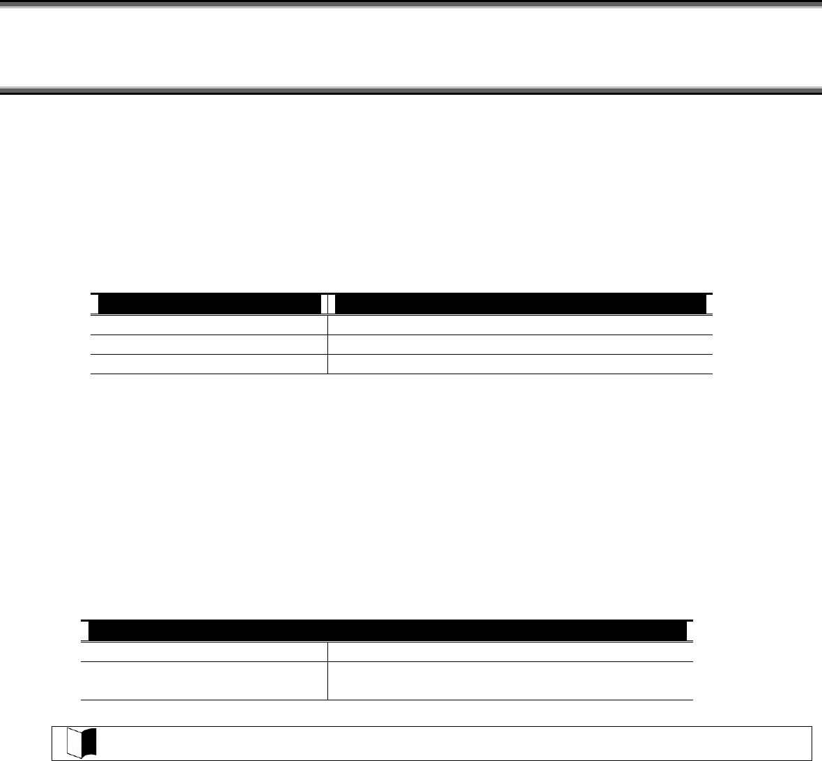
3. If the following dialog box appears, press Enter.
4. If the following dialog box appears, select [標準再セットアップモード(強く推奨)] and press Enter.
5. Follow the direction on the dialog box to provide re-setup.

6. If the following message appears in the middle of the setup, insert the CD-ROMs in the ascending order of ordinal numbers and
press Enter.
次の番号の「再セットアップ用 CD-ROM」をセットし, Enter キーを押してください
→ "Recovery CD-ROM (WinXP) (Second Disk)"
→ "Recovery CD-ROM (WinXP) (Third Disk)"
→ "Recovery CD-ROM (WinXP) (Forth Disk)"
For the subsequent steps, follow the directions on the dialog box.
Now the HDD is completely restored to the factory defaults.
Then provide re-setup for Windows XP.
(5) Re-setup of Windows XP
If the power of FC-N21S is turned on for the first time after system restoration by using the recovery CD-ROMs, the Windows XP
setup job including entry of your name is required. It takes about 30 minutes to complete the job.
1. Reboot FC-N21S after the system restoration job is completed. If the [Welcome to Microsoft Windows] screen appears, click
[Next].
2. The [The End User License Agreement] screen appears. Click the scroll button to read it thoroughly.
3. After reading, click [Yes, I accept]. Then click [Next].
Clicking [No, I don’t accept] disables the setup job to be started.
4. If the [Help protect your PC] dialog box appears, select [Not right now] and click [Next].
5. If the [What’s your computer’s name?] dialog box appears, enter any name in the name field.
−
−
−
−
−
−
The factory default of [Computer name] is "FCN21S-XXXXX" (XXXXX: lowest five digits of product ID).
The computer name can be changed later.
[Computer description] is empty at shipment.
6. Click [Next].
7. If the [What’s your Administrator password?] dialog box appears, enter a password in the password field.
The password field is empty at shipment.
The password is case sensitive.
The password can be changed later. The password entered here must be reentered in the re-setup job. Take note of the password
for remembrance.
8. Click [Next].
9. If message "Is this computer in a domain?" appears, select [Yes] or [No].
(The following describes the operation after you select [No].)
10. Click [Next].
11. Message "Checking your Internet connectivity" appears and then message "How will this computer connect to the Internet?"
appears.
12. Click [Skip].
13. Message "Ready to register with Microsoft" appears.
14. Select "No, not at this time" here.
15. Click [Next].
16. If message "Who will use this computer" appears, enter a user name.
−
−
Default user name: FC-USER
Without entering a user name you cannot advance to the next step

In this case, wait until the desktop screen appears, click [Finish] on the [Introduction to Windows XP] screen and click [Yes] on the
[Change System Settings Screen] screen to restart the system.
After re-booting, the [Welcome to the Found New Hardware Wizard] dialog box may appear.
If this occurs, provide proper settings in the following procedure:
1. If [Welcome to the Found New Hardware Wizard] appears, click " No, not this time " and then click [Next].
2. Click " Install the software automatically " and then click [Next].
Message " Please wait while the wizard installs the software …" appears.
3. If the [Completing the Found New Hardware Wizard] dialog box appears, click [Finish].
Now the operation is completed.
Now the re-setup of Windows XP is completed.
Because WindowsXP automatically recognizes USB keyboard and mouse, specific settings are not required.
In use of a USB keyboard, [Standard 101/102 –Key or Microsoft Natural PS/2 Keyboard] or [PS/2 Compatible
Mouse] may appear when you click [Start] → [All Programs] → [Accessories] → [System Tools] → [System
Information] and select [Components] → [Problem Devices] in the [System Information] dialog box. This is a
view-only problem. The USB keyboard can operate normally without any problems.
If the keyboard or mouse is reconnected, the key layout may be set improperly.
If so, see "(6) Notes on change to keyboard or mouse of different key layout" described below.
(6) Notes on change to keyboard or mouse of different key layout
If the current keyboard or mouse is changed to another one, the new keyboard or mouse may operate improperly. If so, change the key
layout of the keyboard in the following procedure:
1. Click [Start] → [Control Panel].
2. Click [Date, Time, Language, and Regional Options] and [Regional and Language Options].
3. Click [Details…] in [Text services and input languages] of the [Language] tab.
Note: If you find the desired keyboard layout in the list of installed services, go to step 8.
Click [Add] in [Installed services].
4. Select the language of the keyboard layout to be added from the [Input language:] list.
5. If [Keyboard layout/IME:] has only a single option, click the option.
If more than one options are available, open pull-down menu [Keyboard layout/IME:] and select the desired option from the list.
6. Click [OK].
7. Click the language of the used keyboard layout from the [Default input language] list.
8. Click [OK].
9. Click [OK].
5.1.4.2
5.1.4.3
Installing Attached Applications
Install attached applications with re-setup.
For the re-setup procedure, see "5.2 Installing Attached Applications".
Providing Settings Made after Purchase Again
Any settings made after purchase are discarded by re-setup. Provide the settings again.
Reconnect peripherals purchased separately if any and provide settings for the peripherals again. Also make network setting.
In addition, reinstall applications purchased separately and having been installed if any.
5.1.5 Custom Re-setup
The HDD can be restored to specified status by using the attached Recovery CD-ROMs.
5.1.5.1
5.1.5.2
Checking Items
(1) Tools to be prepared
The following tools are required for re-setup by using the recovery CD-ROMs.
Prepare the following CD-ROMs attached to FC-N21S.
Recovery CD-ROM (WinXP)
CD-R/RW with DVD-ROM drive (FC-CW002U)
In addition, the user name and the computer name must be entered.
Define the names to be registered previously.
(2) Check items before re-setup
Be sure to return BIOS settings to the factory defaults if changed.
For how to return BIOS settings to the factory defaults, see "4.1.3 Loading the BIOS SETUP Defaults".
(3) Notes on re-setup
Do not connect or add peripherals including a printer or memory devices.
Before the re-setup is completed, any peripherals including a printer and extended memory devices should never be connected to
FC-N21S. If these peripherals are purchased concurrently with FC-N21S, first complete the setup of Windows XP to be followed
by connections and installations of the peripherals according to the user’s guides coming with the peripherals.
Do not turn off the power on the way.
Do not turn off the power in the middle of the setup. Setting the power switch to OFF or disconnecting the power cable in the
middle of the setup may cause a fault to occur. If the screen seems to stop on the way, the setup program may operate. This does
not indicate that the system is defected. Advance the operation according to the defined procedure without panic.
System Restoration Procedure
1. Turn on the power of FC-N21S.
2. If the power lamp goes on, insert the first Recovery CD-ROM disk (WinXP) in the CD-ROM drive.
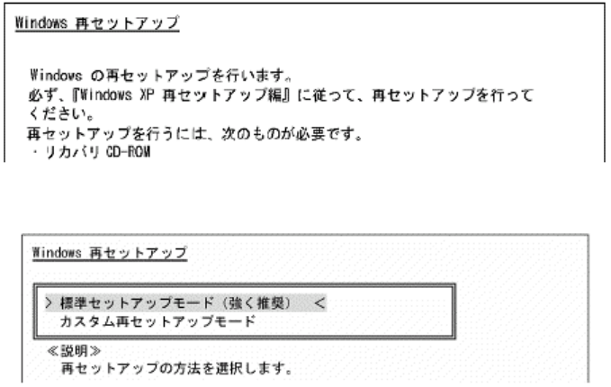
3. If the following dialog box appears, then press Enter.
4. If the following dialog box appears, select [カスタム再セットアップモード] and press Enter.
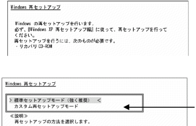
5. The followin
g
dialo
g
box a
pp
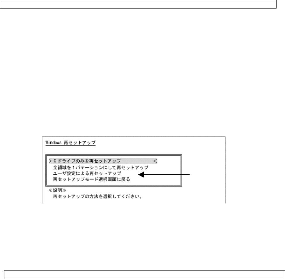
ears.
(1) [C ドライブのみを再セットアップ]
(2) [全領域を 1パーティションにして再セットアップ]
(3) [ユーザ設定による再セットアップ]
(1) Re-setup of drive C only (NTFS)
If the HDD to be subject to re-setup has an unassigned area larger than drive C, re-setup of drive C only may be disabled.
If so, retain the unassigned area as a partition before selecting [C ドライブのみを再セットアップ].
1. If the following dialog box appears, select [C ドライブのみを再セットアップ] and press Enter.
2. If message "C ドライブに Windows XP を再セットアップします。よろしいですか?" appears on the dialog box, select
[Yes] and press Enter.
3. If the following message appears in the middle of the setup, insert the CD-ROMs in the ascending order of ordinal numbers and
press Enter.
次の番号の「再セットアップ用 CD-ROM」をセットし, Enter キーを押してください
→ "Recovery CD-ROM (WinXP) (Second Disk)"
→ "Recovery CD-ROM (WinXP) (Third Disk)"
→ "Recovery CD-ROM (WinXP) (Third Disk)"
For the subsequent steps, follow the directions on the dialog box.
If the [Windows XP Setup Wizard] dialog box appears after restarting, then the following operation is the same as that for the standard
re-setup.
Perform the operation according to the description in "5.1.4.1 Repairing System by Using Recovery CD-ROMs".
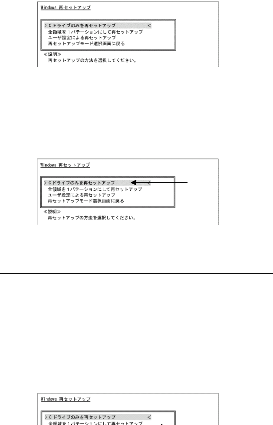
(2) Re-setup by combining entire area into a single partition (NTFS)
Select [全領域を 1パーティションにして再セットアップ] on the [WindowsXP 再セットアップ] dialog box and press Enter.
1. If the following dialog box appears, select [全領域を 1パーティションにして再セットアップ] and press Enter.
3. If the following message appears in the middle of the setup, insert the CD-ROMs in the ascending order of ordinal numbers and
press Enter.
次の番号の「再セットアップ用 CD-ROM」をセットし, Enter キーを押してください
→ "Recovery CD-ROM (WinXP) (Second Disk)"
→ "Recovery CD-ROM (WinXP) (Third Disk)"
→ "Recovery CD-ROM (WinXP) (Forth Disk)"
For the subsequent steps, follow the directions on the dialog box.
If the [Welcome to Microsoft Windows] dialog box appears after restarting, then the following operation is the same as that for the
standard re-setup.
Perform the operation according to the description in "5.1.4.1 Repairing System by Using Recovery CD-ROMs".
(3) Re-setup with free setting of HDD area (NFTS)
Select [ユーザ設定による再セットアップ] on the [WindowsXP 再セットアップ] dialog box and press Enter.
1. If the following dialog box appears, select [ユーザ設定による再セットアップ] and press Enter.
2. If message "ドライブのサイズを GB 単位で指定できます。" appears, enter the desired capacity of drive C by using the
numeric keypad. The range from 5GB to 82GB can be specified. However, you cannot specify any capacity larger than the
capacity of the HDD.
3. If message "この設定でよろしければ F8 キーを押してください。" appears, make sure that the specified value is displayed
and press F8.
4. If the following message appears in the middle of the setup, insert the CD-ROMs in the ascending order of ordinal numbers and
press Enter.
次の番号の「再セットアップ用 CD-ROM」をセットし, Enter キーを押してください
→ "Recovery CD-ROM (WinXP) (Second Disk)"
→ "Recovery CD-ROM (WinXP) (Third Disk)"
→ "Recovery CD-ROM (WinXP) (Forth Disk)"
For the subsequent steps, follow the directions on the dialog box.
If the [Welcome to Microsoft Windows] dialog box appears after restarting, then the following operation is the same as that for the standard
re-setup.
Perform the operation according to the description in "5.1.4.1 Repairing System by Using Recovery CD-ROMs".

5.1.6 "Microsoft Windows XP Service Pack 2"
The OS installed in FC-N21S of Windows XP pre-installed model is "Microsoft Windows XP Service Pack 2" (called Service Pack 2
below).
Service Pack 2 includes a set of update programs intended to improve or correct faults and problems found after the first supply of
Windows XP.
Addition/deletion
Do not delete Service Pack 2 from FC-N21S.
Some device drivers are only applicable to Service Pack 2. Thus, deleting Service Pack 2 may cause some
drivers to be operated improperly.
修
正
The latest and other information on Windows XP is provided on the following web site. Access the site
periodically.
http://www.microsoft.com/windowsxp/downloads/

5.2 INSTALLING ATTACHED APPLICATIONS
5.2.1 Fingerprint Authentication Utility
A set of installation software is saved in drive C and thus no CD-ROM drive is required.
(1) Overview
The fingerprint authentication allows the following features to be executed:
Logon to Windows and unlock the screen saver
Substituting for passwords of applications (protecting important files)
(2) Supporting OSs
Microsoft Windows XP, Japanese Ver. (SP2)
Microsoft Windows XP, English Ver. (SP2)
(3) Installation procedure
1. Start Windows.
2. Click [Start] → [Control Panel].
3. Double-click [Add or Remove Programs].
4. Click [CD or Floppy] on the [Add new Programs] tab.
5. If message "Install Program From Floppy Disk or CD-ROM, and then click Next." appears, click [Next].
6. Click [Browse…] and change the file type to [Program].
Specify "C:\WINXP\Fingerprint Sensor\autorun.exe" and click [Open].
7. The menu window appears. Click [Software Installation].
8. Follow the directions on the window. For details of installation, see "C:\WINXP\FingerprintSensor\doc\0411\Manual.pdf".
9. After the installation is completed, reboot FC-N21S.
Now the Fingerprint Authentication Utility is completely installed.
(4) Usage
To browse the following documentation file, Acrobat Reader 7.0 must be installed.
1. Start Windows.
2. Click [Start] → [Settings] → [Control Panel].
3. Double-click [Add or Remove Program].
4. Click [CD or Floppy] on the [Add new Programs] tab.
5. If message "Install Program From Floppy Disk or CD-ROM, and then click Next." appears, click [Next].
6. Click [Browse…], specify "C:\WINXP\Fingerprint Sensor\autorun.exe" and click [OK].
7. The menu dialog box appears. Click [Documentation].
8. Open "Manual.pdf" to check usages including the fingerprint registration procedure.
(5) Deletion procedure
1. Start Windows.
2. Click [Start] → [Settings] → [Control Panel].
3
Dbl
li k
[Add R P ]

Now the fingerprint authentication utility is removed completely.
Data saved in the biometric device (chip for fingerprint sensor) is not erased even if the built-in HDD is erased.
See "C:\WINXP\Fingerprint Sensor\doc\0411\Manual.pdf" to uninstall the fingerprint authentication utility in the
proper procedure.
5.2.2 Infineon Security Platform
A set of installation software is saved in drive C and thus no CD-ROM drive is required.
(1) Overview
Using Infineon Security Platform allows electronic mails and files to be encrypted and prohibited from being opened without
authentication password.
In addition, FC-N21S is equipped with a security chip called TPM (Trusted Platform Module) in its major part to store encryption
keys in the security chip. Thus, if only the HDD is withdrawn, the data in the HDD will not be read.
(2) Supporting OSs
Microsoft Windows XP, Japanese Ver. (SP2)
Microsoft Windows XP, English Ver. (SP2)
(3) BIOS setting procedure
Set BIOS in the following procedure.
To use the security chip, set supervisor and user passwords to restrict accessing to the BIOS SETUP Utility.
1. After power-on of FC-N21S, the BIOS start screen (with NEC logo displayed at the center) appears. If message "Press <F2> to
SETUP or Press <F12> to Network boot." appears, press F2.
2. After the BIOS SETUP Utility menu appears, select [Security].
3. Select [Security Chip Configuration] and press Enter.
4. Select [Security Chip] and press Enter.
5. Select [Enabled] and press Enter.
6. Item [Security Platform] appears. Select it and press Enter.
7. Select [Enabled] and press Enter.
8. Press F10 to open the [Save configuration changes and exit now?] dialog box. Select [Yes] and press Enter. An attempt is made
to restart BIOS.
9. After restarting, the [Physical Presence Operations] dialog box is opened.
10. Select [Execute] and press Enter to try to restart BIOS.
(4) Installation procedure
1. Start Windows.
Just after BIOS setting, the hardware add wizard requests driver installation. However, the driver can be
installed in the following procedure. you may cancel the hardware add wizard.
2. Click [Start] → [Settings] → [Control Panel].
3. Double-click [Add or Remove Program].
4. Click [CD or Floppy] on the [Add new Programs] tab.
5. If message "Install Program From Floppy Disk or CD-ROM, and then click Next." appears, click [Next].
6. Click [Browse…], specify "C:\WINXP\TPM\Setup.exe" and click [OK].
(6) Usage
For details of the features, operations and restrictions of the Infineon Security Platform, see
"C:\WINXP\TPM\Readme\JP\Readme.txt".
(7) Deletion procedure
1. Start Windows.
2. Click [Start] → [Control Panel].
3. Double-click [Add or Remove Programs].
4. Click [Infineon TPM Professional Package] and [Change/Remove].
5. If the [Confirm File Deletion] dialog box appears, click [Yes].
6. Follow the directions on the dialog box to uninstall the fingerprint authentication utility.
7. After the uninstallation is completed, reboot FC-N21S.
Now the Infineon Security Platform is deleted completely.
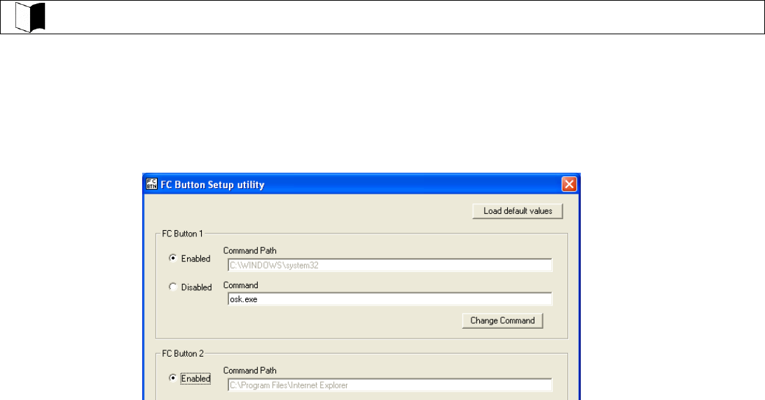
5.2.3 FC Button Setting Tool
(1) Overview
The tablet buttons at the lower left corner of the LCD display can be assigned new features different from their original ones by using
the BIOS SETUP Utility.
If any of the keys are assigned [FC button 1] and/or [FC button 2], the execution commands (or application starts) registered on the
[FC Button Setup utility] dialog box can be run.
(2) Supporting OSs
Microsoft Windows XP, Japanese Ver. (SP2)
Microsoft Windows XP, English Ver. (SP2)
(3) Usage
To use the feature, any of the tablet buttons must be assigned [FC button 1] and [FC button 2] on the BIOS SETUP Utility.
For BIOS settings, see "4.3.4 Tablet Button Submenu".
See C:\WINXP\FCBTN\FCbtnReadme.txt for details.
(4) Start procedure
Click [Start] → [All Programs] → [FC Button Setup utility].
The [FC Button Setup utility] dialog box shown below appears. Set the buttons appropriately.

5.3 OTHER OSS AND APPLICATIONS
(1) FC-N21C of Linux pre-installed model
FC-N21S of Linux pre-installed model (delivered when you select [Linux pre-installed] on the Selection Menu) contains an
accompanying CD-ROM different from that of another model.
For use of FC-N21C of Linux pre-installed model, refer to the PDF documentation stored in attached CD-ROM
"DeveloperCD".
(2) CD-R/RW with DVD-ROM drive
Option FC-CW002U (external CD-R/RW with DVD-ROM drive) contains writing tool. A DVD video replay tool is commercially
available.
(3) FC-N21C of Linux pre-installed model of English version
For FC-N21C of Linux pre-installed model of English version, the re-setup procedure by using the attached recovery CD-ROM is the
same as that for FC-N21C of Linux pre-installed model of Japanese version.
FC-N21C of Linux pre-installed model of English version can run the following applications among those attached to FC-N21S.
<Applications available to FC-N21C of Linux pre-installed model of English version >
Fingerprint Authentication Utility
Infineon Security Platform
FC Button Setting Tool

Chapter 6 Security
6.1 SETTING PASSWORD ON BIOS SETUP UTILITY
You can set a password intended to limit users of starting the system on the BIOS SETUP Utility.
If you set a password, any user must enter the password for the following operations. This can increase the security feature:
Starting BIOS SETUP Utility
Starting system
6.1.1 Security by Password at Start of BIOS SETUP Utility
Setting supervisor and user passwords on the BIOS SETUP Utility can limit users of starting the system.
If you set a password, any user must enter the password for the following operations:
Starting BIOS SETUP Utility
Starting system.
This can increase the security feature:
Any user starting the BIOS SETUP Utility with the user password can only provide limited items with settings. This can prohibit users
from changing important items if he or she is not the administrator of the specific PC.
For the password setting procedure, see "4.4.1 Security".
6.1.2 HDD Password
You can set a password for the HDD (primary master)
If a HDD password is set for a PC, the password must be entered to another PC in which this HDD is installed.
The HDD password is intended to prevent the HDD from being used illegally in a PC other than yours. Even if a
HDD password is set, entering the password is not required on booting your PC.
There are two HDD passwords, or HDD master and HDD user passwords.
The HDD master password is intended to release the HDD user password.
The HDD user password is intended to authenticate your PC and the HDD installed in the PC.
For the setting procedure, see "4.4.1 Security".
6.2 I/O LOCK FEATURE
The I/O lock disables the I/O feature, measures to interchange data with external devices, on the BIOS SETUP Utility.
To use the I/O lock feature, set supervisor and user passwords to limit accessing to the BIOS SETUP Utility.

6.3 LOGIN PASSWORD
The login password is intended to limit users of OS.
If a login password is set, the password must be entered to login to the OS.
<Setting Procedure>
1. Click [Start] → [Control Panel].
2. Click [User Accounts] to open the dialog box.
3. Click [Change an account] and click the name of the user for which a login password is to be created.
4. Click [Create a password] to open the password setting screen.
5. Enter a password in the [Type a new password:] and [Type the new password again to confirm:] boxes and click [Create
password].
A login password can be created only by a user having any of accounts in the local PC including guest and
administrator accounts and those created for the PC.
To create a tip for a password, anyone using PCs can see the tips on the [Welcome] screen.
A user having the administrator account of a PC can create or change passwords for all users of the PC. A
user having a limited account can only create or change his or her own password or create a tip of the
password.
If a user having the administrator account of a PC changes a password of a user, then the user loses all the
passwords stored for EFS encrypted files, personal certificate, and web site or network resources.
6.4 SECURITY CHIP
Setting the security chip allows electronic mails and files to be encrypted and prohibited from being opened without an authentication
password.
In addition, FC-N21S is equipped with a security chip called TPM (Trusted Platform Module) in its major part to store encryption keys in
the security chip. Thus, if only the HDD is withdrawn, the data in the HDD will not be read.
To use the security chip, set supervisor and user passwords to restrict accessing to the BIOS SETUP Utility.
See "5.2.2 Infineon Security Platform" for details.
6.5 FINGERPRINT AUTHENTICATION PASSWORD
The fingerprint authentication password is intended to provide authentication by fingerprints using the built-in fingerprint sensor instead of
passwords.
FC-N21S has an attached utility to allow logon to Windows, release of screen saver lock and substitution for passwords of various
applications by fingerprint authentication.
For the attached utility, see "5.2.1 Fingerprint Authentication Utility".
6.6 ANTITHEFT LOCK
A commercial security cable can be used to tie FC-N21S to a desk or so. This is effective to prevent FC-N21S itself from being stolen.
The antitheft lock hole has the size of 3mm×7mm. Select a security cable fit to the hole.
Take sufficient care for management and treatment of important data without overconfidence of the security
cable.
Chapter 7 Options
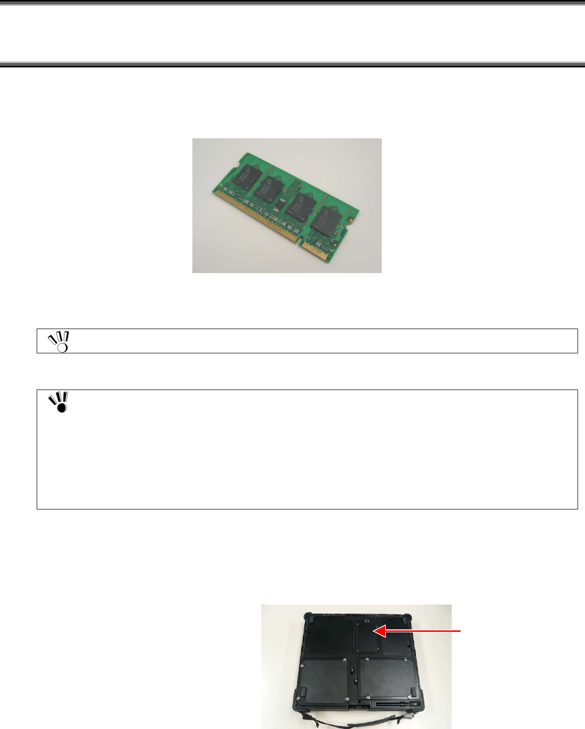
7.1 EXTENDED RAM BOARDS FC-UG-M011 (256MB), FC-UG-M012 (512MB) AND FC-UG-M013 (1GB)
FC-N21S can be equipped with an extended RAM board of an option to operate more applications concurrently and/or process larger data
at higher speed.
Be sure to select an extended RAM board specified as an option of FC-N21S if installed.
(1) Installation procedure of extended RAM board
Extended RAM boards are extremely sensitive to static electricity. Making your body charged
electrostatically contact with an extended RAM board may cause the board to be damaged. Before you can
handle an extended RAM board, you should discharge static electricity from your body by touching a metallic
component found near you including aluminum sash and a doorknob
Do not make your hands contact with the connector of each extended RAM board. Failure to follow this
instruction may cause a fault such as poor connection to occur.
Be careful not to make your hands contact with parts and soldering on each extended RAM board.
Trying to insert an extended RAM board into the mating connector of FC-N21S in invalid orientation may
cause the board and/or the connector to be defected. Note the orientation.
Before installing an extended RAM board in FC-N21S, confirm that the board is available to FC-N21S.
1. Turn off the power of FC-N21S if operated.
2. Unplug the power cord from the AC outlet and remove the AC adapter from FC-N21S.
3. Close the LCD display panel and turn FC-N21S upside down.
4. Remove the battery pack from FC-N21S. See "3.4.5 Replacing Battery" for the removal procedure.
5. Remove the screws (4) fixing the memory slot cover and remove the memory slot cover.
Memory slot cover
Insert the extended RAM board to the mating connector in FC-N21S to the depth at insertion angle of about 30°.
The extended RAM board cannot be inserted to the mating connector on FC-N21S in the reversed
orientation. Check the front and rear sides of the board securely.
Hold both ends of an extended RAM board if you must handle the board.
It may be hard to insert an extended RAM board into the mating connector on FC-N21S. Push the board to
the depth securely. If not, the connector may be damaged in the next step.
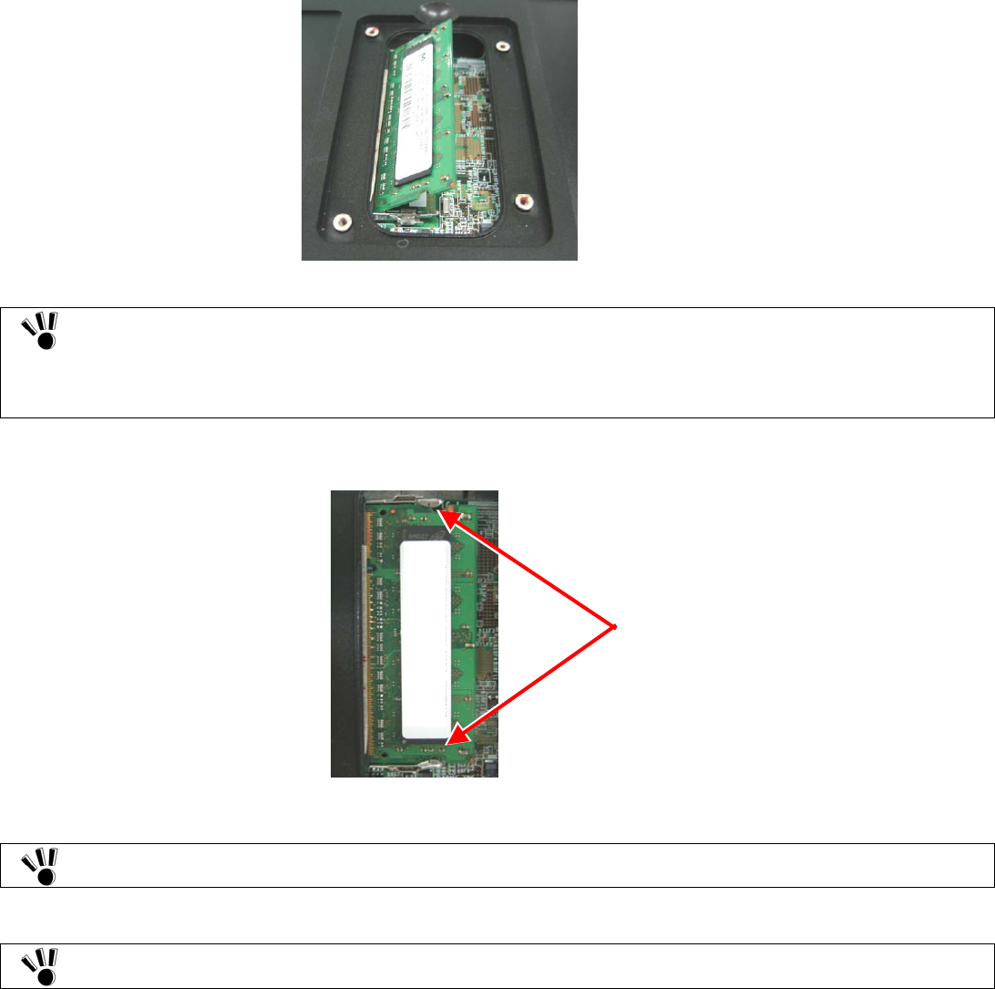
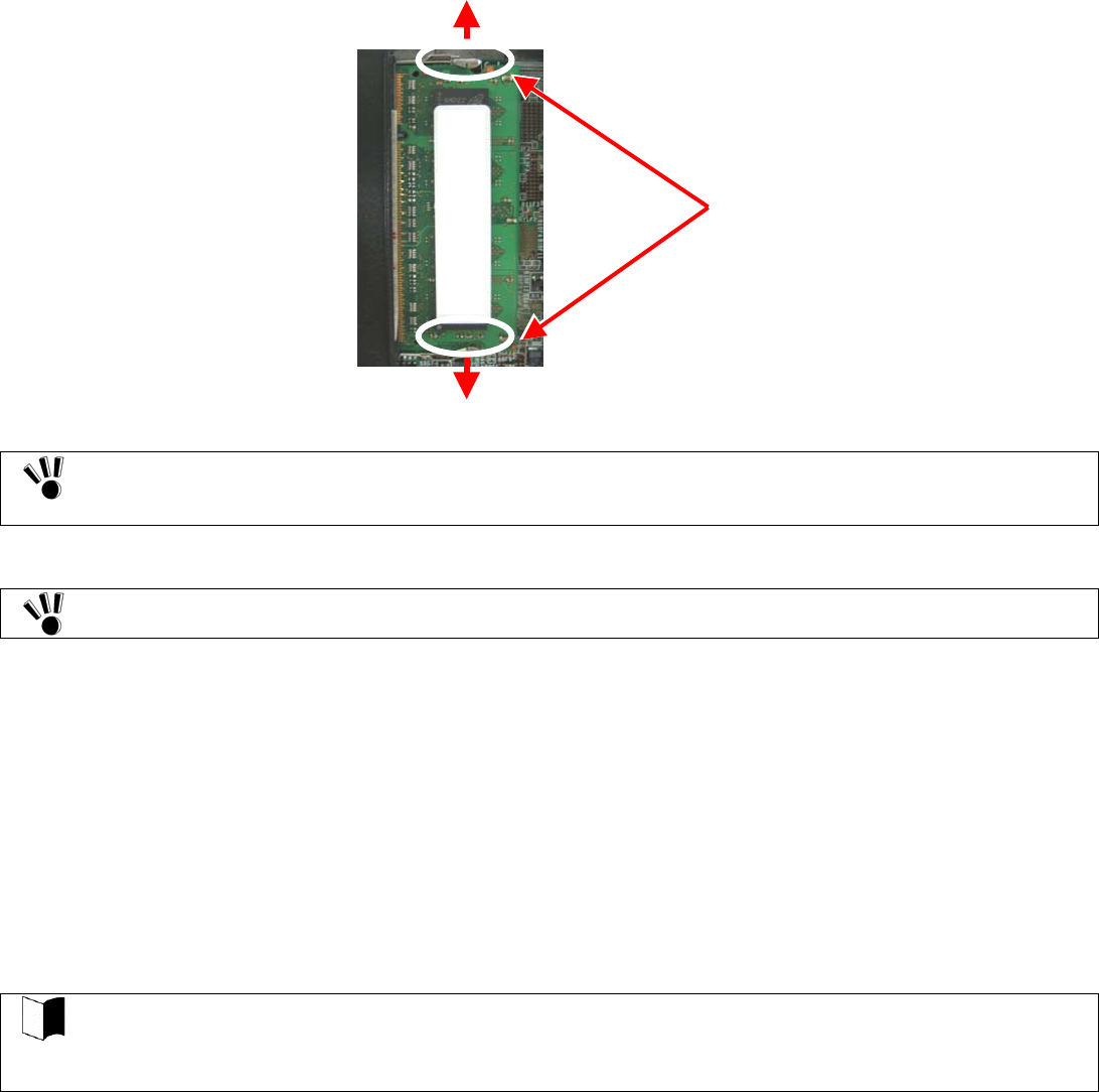
6. Push the board down to FC-N21S intensely until a click occurs.
Locked here
Confirm that the board is securely locked by hooks.
7. Put the memory slot cover to the original position and drive the screws (4) to fix the cover.
If dust and/or dirt adhere to the silicon rubber on rear of the cover, the water-proof and dust-proof of the cover
may be reduced. Wipe the silicon rubber to remove dust and dirt before installing the cover.
8. Install the battery pack in FC-N21S and connect the AC adapter to FC-N21S. See "3.4.1 Installing Battery" for the battery
installation procedure.
(2) Extended RAM board removal procedure
1. Remove the memory slot cover according to steps 1 to 5 in "(1) Installation procedure of extended RAM board".
2. Push the hooks outwards to let the extended RAM board rise. Then pull out the board.
Push the hooks outward to release
the lock and let the board rise.
Extended RAM boards can be damaged easily because they are rather thin. Handle them carefully.
Be careful not to make your hands contact with parts and soldering on extended RAM boards.
To pull out an expended RAM board from the mating connector, hold both ends of the board.
3. Put the memory slot cover to the original position and drive the screws (4) to fix the cover.
If dust and/or dirt adhere to the silicon rubber on rear of the cover, the water-proof and dust-proof of the cover
may be reduced. Wipe the silicon rubber to remove dust and dirt before installing the cover.
4. Install the battery pack in FC-N21S and connect the AC adapter to FC-N21S.
(3) Extended RAM confirmation procedure
For Windows XP:
1. Click [Start] → [Control Panel] → [Performance and Maintenance] → [System]. Then the [System Properties] dialog box
appears.
2. Check the data appearing at the lower right corner in the [General] tab. [***KB RAM] or [***MB of RAM] should appear
(where "***KB" or "***MB" is the total memory capacity).
If the memory capacity does not increase, check if the extended RAM board is installed appropriately again.
Depending on the system status, the value may be smaller than the actual total capacity. However, this does
not result from occurrence of an error.
To use a feature in the pause state after memory extension, the empty capacity by the extended memory
capacity is required in the HDD. Check the capacity of the HDD.
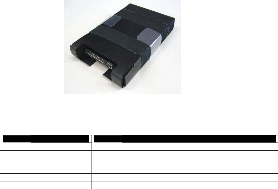
7.2 HARD DISK DRIVE FC-HD60KN (STANDARD)
Spare HDD FC-HD60KN can be replaced with the HDD installed in FC-N21S of standard model.
(1) Specification of HDD (standard)
Item Specification
Total storage capacity 60GB
Number of revolutions 5,400 rpm
Average seek time 12 ms
External dimension 78(W) × 120(D) × 19(H) mm
Weight About 120 g
(2) HDD removal procedure
HDDs are extremely precise equipment. Note the following if used.
During data read/write (with the access lamp being ON), only a small shock may cause the HDD to be
defected.
If the HDD is defected, important data may be unavailable at a time and unable to be restored. It is
recommended to frequently back up important data for which the same data cannot be created twice.
Depending on models of HDDs, a region with no drive number assigned appears in the [Disk Management]
dialog box. This is the re-setup region required for re-setup. Do not provide the region with such processing
as deletion from targets of disk management.
1. Turn off the power of FC-N21S if operated.
2. Unplug the power cord from the AC outlet and remove the AC adapter from FC-N21S.
3. Close the LCD display panel and turn FC-N21S upside down.
4. Remove the battery pack from FC-N21S. See "3.4.5 Replacing Battery" for the removal procedure.
5. Remove the screws (4) fixing the disk cover and remove the disk cover.
Disk cover
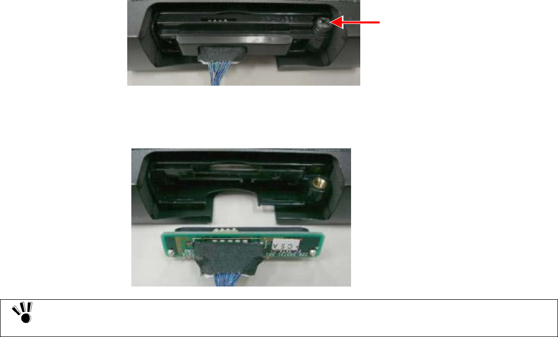
7. Remove the screw (1) fixing the connector cover and remove the connector cover.
8. Remove the small board with cable from the connector on the HDD.
Screw for fixing connector cover
Be careful sufficiently not to damage the connector and other parts by pulling out the connector at an
improper angle.
To pull out the connector, hold both ends of the board.
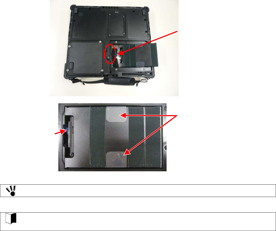
(3) HDD installation procedure
1. Connect the small board with cable to the connector on a new HDD.
2. Install the connector cover and drive the screw (1) to fix the cover.
3. Put remaining cable into the space shown in the photo below and install the HDD with the take-out support pulled out.
Put remaining cable in this space.
HDD take-out support
Cable
The HDD cannot be inserted to the mating connector on FC-N21S in the reversed orientation. Check the front
and rear sides of the HDD securely.
4. Put the disk cover to the original position and drive the screws (4) to fix the cover.
Put the cover so that the HDD removal support may not be caught.
If dust and/or dirt adhere to the silicon rubber on rear of the cover, the water-proof and dust-proof of the
cover may be reduced. Wipe the silicon rubber to remove dust and dirt before installing the cover.
5. Install the battery pack in FC-N21S and connect the AC adapter to FC-N21S. See "3.4.1 Installing Battery" for the battery
installation procedure.
7.3 HARD DISK DRIVE FOR WIDE TEMPERATURE RANGE FC-HD40KN
The spare HDD can be replaced with the HDD installed in FC-N21S of wide temperature range HDD model. The HDD is unavailable to
FC-N21S of any other models.
(1) Specification of HDD (standard)
Item Specification
Total recording capacity 40GB
Number of revolutions 4,200rpm
Average seek time 12ms
Outer dimension (approximation) 78 (W) × 120 (D) × 19 (H) mm
Weight About 116g
Interface UltraATA
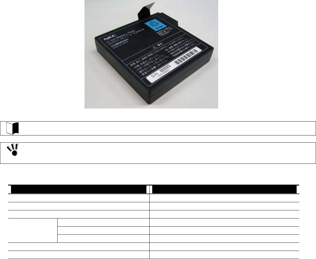
7.4 SPARE BATTERY FC-N011 (STANDARD TYPE)
Spare battery FC-N011 (lithium ion battery) can be replaced with the battery installed in FC-N21S (standard model).
For battery replacement, see "3.4.5 Replacing Battery".
If a battery of an invalid type is substituted for the old one, it may explode.
Do not use FC-N011 for other than FC-N21S (standard model). For used batteries, see "3.4.6 Recycling
Batteries".
(1) Specification of FC-N011
Item Specification
Type Lithium ion battery
Rating voltage 11.1 VDC
Capacity 5.2 Ah (initial)
Operating (charging) 0 to 45ºC
Operating (discharging) –20 to 60ºC
Temperature
Storage –20 to 60ºC (for up to 1 month)
Outside dimension 95.7 (W) × 93.1 (D) × 19.3 (H) mm (*excluding projections)
Weight About 0.33 kg
(2) Handling FC-N011
1. Status of FC-N011 at the time of purchase
FC-N011 is not charged fully at purchase.
2. Handling of battery in use or charge
Install FC-N011 in FC-N21S or battery charger FC-N013 of an option and connect the AC adapter to FC-N21S or FC-N013.
Then charging FC-N011 is started. It takes about three hours to charge FC-N011 fully.
With the AC adapter connected to FC-N212S, the battery is still charged if the power of FC-N21S is OFF.
Charge the battery in temperature range 5 to 40ºC. Charging the battery at a higher temperature may cause it to be deteriorated
or damaged.
It takes a longer time to charge the battery fully at a low temperature than to charge it fully at a normal temperature.
The time taken to charge the battery fully may vary depending on conditions under which FC-N21S is used.
At a lower temperature, FC-N21S can operate only for a shorter period.
3
Handling of battery in storage
7.5 AC ADAPTER
AC Adapter is shipped with FC-N21S. The AC adapter converts AC power to DC power to supply the DC power to FC-N21S.
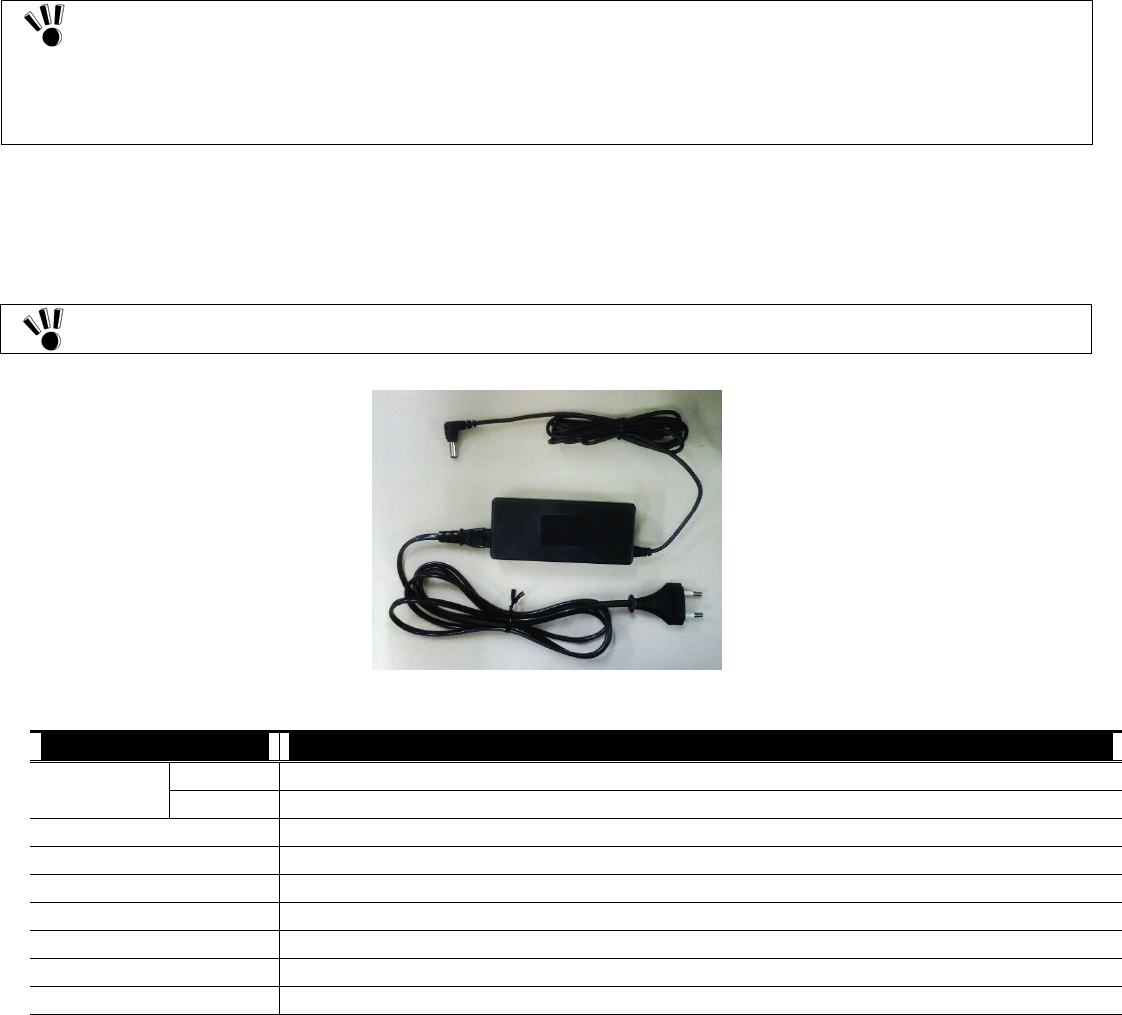
7.5.1 AC ADAPTER FC-N012EU (For Europe)
The AC adapter can operate in the voltage range from 100 VAC to 240 VAC. The AC cord shipped with FC-N21S can be used for 240
VA C .
The AC adapter is designed on the assumption that it is connected to FC-N21S. The AC adapter may be
damaged if it is connected to a device other than FC-N21S.
In removal of the AC adapter, first pull out a plug from the mating power outlet and then the other plug from
FC-N21S. Removing the plugs in the reserve order may cause the AC adapter and/or FC-N21S to be
damaged.
Always hold the plugs of the AC adapter in its removal. Do not pull the cord.
The AC adapter (FC-N012EU) and the AC cord shipped with FC-N21S are intended to be used only in the
specified country.
FC-
N
代
わ
FC-
N
,US,
A
載。
(1) Specification of AC adapter(FC-N012EU)
Item Specification
Operating 5 to 35ºC Temperature
Storage –10 to 70ºC
Humidity 20 to 80% RH (without condensation)
Input voltage 100 to 240 VAC (±10%), 1.5 A, 50/60 Hz (±5%) (The AC cord can be used for 240 VAC.)
Output voltage 16 VDC (±5%), 3.75 A
Maximum power 60 W
Cable length 1.8 m (AC cord: about 2 m)
Outside dimension 114.5 (W) × 50.5 (D) × 28 (H) mm
Weight About 0.4 kg (including AC cord)
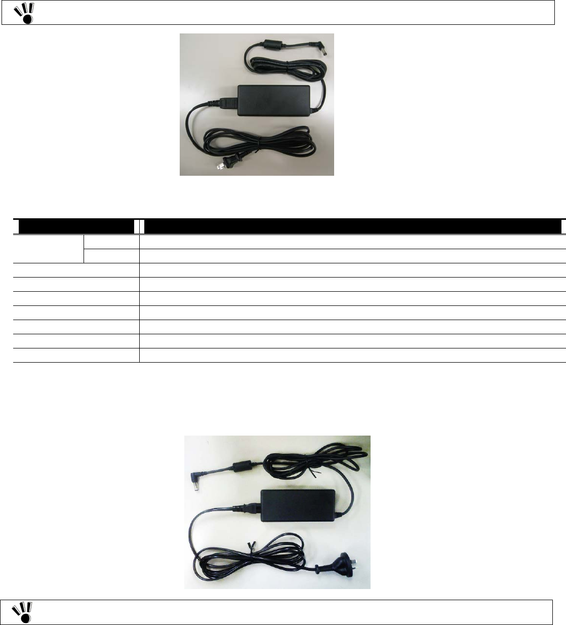
7.5.2 AC ADAPTER FC-N012US (For U.S.A)
The AC adapter can operate in the voltage range from 100 VAC to 240 VAC. However, the AC cord shipped with FC-N21S can be
exclusively used for 100 VAC.
(1) Specification of AC adapter(FC-N012US)
Item Specification
Operating 5 to 40ºC Temperature
Storage –10 to 70ºC
Humidity 5 to 95% RH (without condensation)
Input voltage 100 to 240 VAC (±10%), 1.5 A, 50/60 Hz (±5%) (The AC cord can be exclusively used for 100 VAC.)
Output voltage 16 VDC (±5%), 4.5 A
Maximum power 72 W
Cable length 1.8 m (AC cord: about 2 m)
Outside dimension 115.4 (W) × 51 (D) × 28 (H) mm
Weight About 0.46 kg (including AC cord)
7.5.3 AC ADAPTER FC-N012AS (For Australia)
The AC adapter can operate in the voltage range from 100 VAC to 240 VAC. The AC cord shipped with FC-N21S can be used for 240
VA C .
The AC adapter (FC-N012US) and the AC cord shipped with FC-N21S are intended to be used only in US.
The AC adapter (FC-N012AS) and the AC cord shipped with FC-N21S are intended to be used only in
Australia.
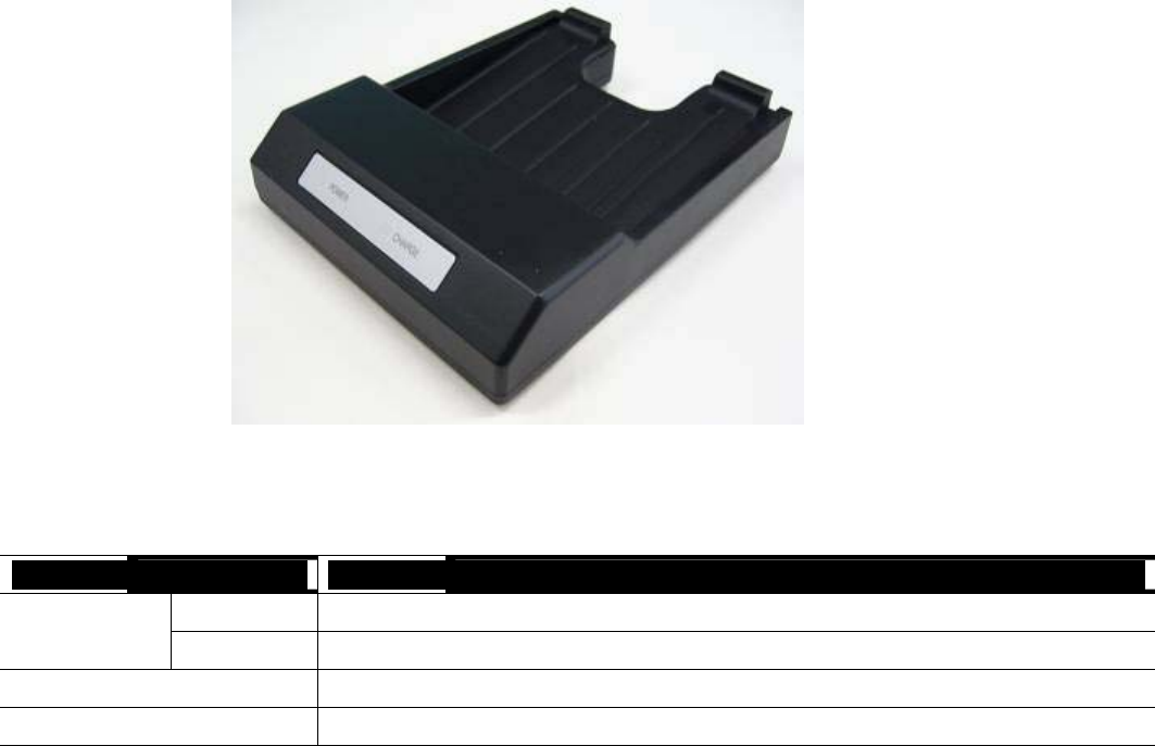
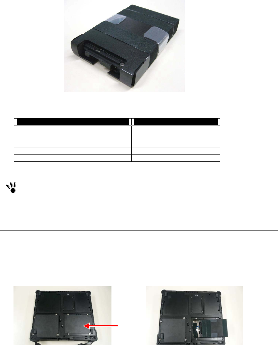
7.6 BATTERY CHARGER FC-N013
The battery charger is an adapter intended to charge the battery in FC-N21S. For proper use, the battery charger must be combined with the
AC adapter coming with FC-N21S or the car adapter of an option.
(1) Specification of battery charger
Item Specification
Operating 0 to 45ºC
Temperature Storage –20 to 70ºC
Outer dimension 145 (W) × 110 (D) × 29 (H) mm *Excluding projections (including cover and feet)
Weight About 0.15 kg

Chapter 8 Maintenance
8.1 TROUBLESHOOTING
8.1.1 Flowchart
This section describes many solutions to troubles. If a trouble occurs, see the section to find the solution to the trouble according to the
procedure below.
If a trouble occurs, first refer to the guide.
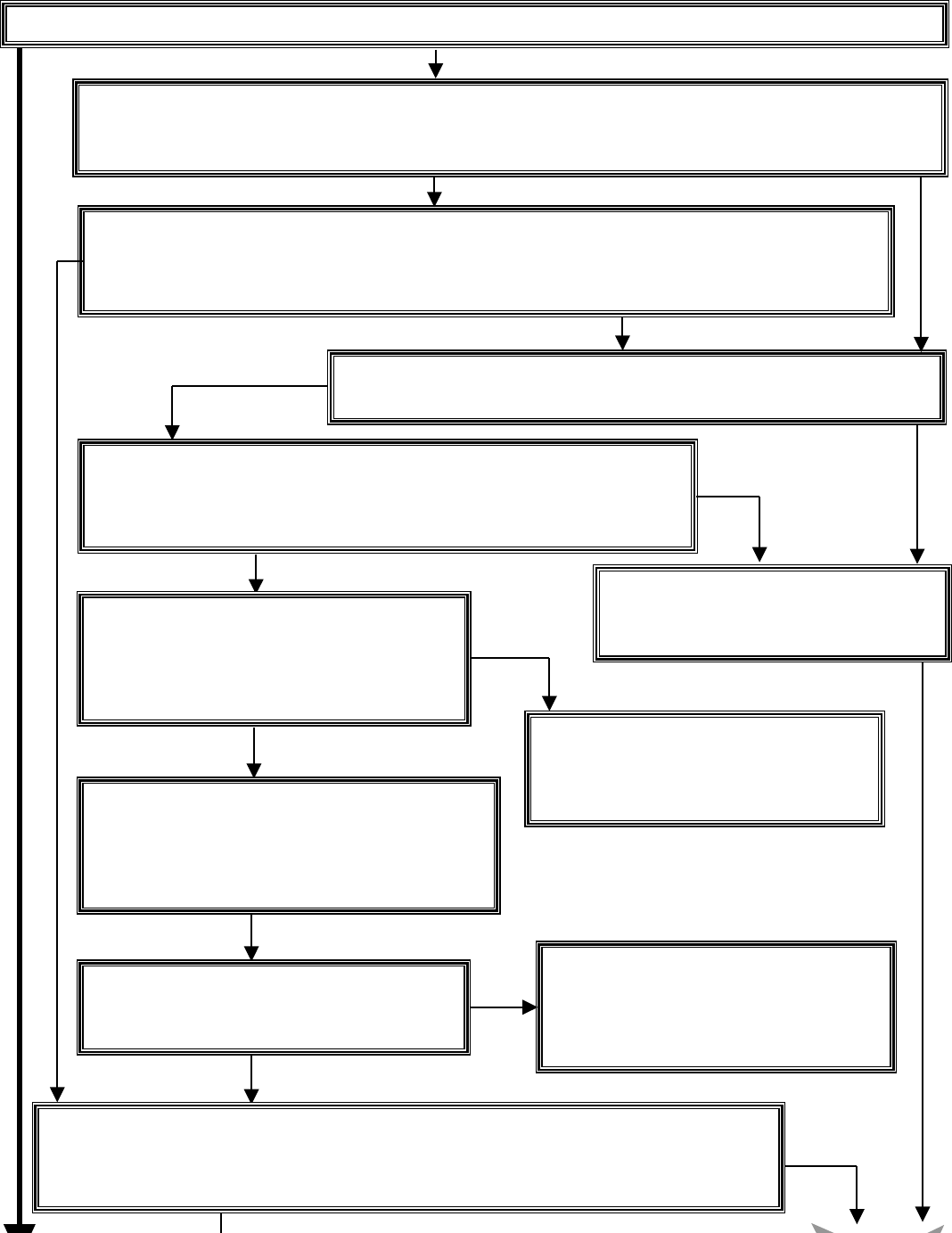
If sm et. oke, odor or noise is generated, turn off the power immediately and pull out the plug of the power cord from AC outl
Is FC-N21S booted normally?
If the NEC Logo screen does not appear (excluding the case where BIOS is set not to display the NEC Logo
message "Operating system not found" appears in FC-N21S booting, a hardware error may occur.
Boot FC-N21S in safe mode.
If FC-N21S is not booted normally, boot it in the safe mode to check the status and/or change some settings.
For how to boot FC-N21S in the safe mode, see "5.1.3.2 Booting FC-N21S in safe mode" in "Chapter 5
Installing OS and Applications."
N
o
Booted normally
Booted
N
ot booted
Search for applicable information.
Search "8.3.3 Troubleshooting Q&A" for the situation in which a trouble o
N
o applicable
Check hints.
If applicable actions are not found or some measures cannot resolve the symptom,
see "8.3.2 Actions Taken to Solve Trouble (Tips)." The section describes tips to
solve troubles.
N
o tips found
Take actions.
Take action according to the relevant ev
"8.3.3 Troubleshooting Q&A."
Remove peripheral devices.
If the troubles cannot be solved still, turn off the
power. Remove added peripheral devices
(including expanded board, memory and hard disk)
and check if FC-N21S operates normally.
N
ot soluble
Check peripheral devices.
To check if a peripheral device is available to
FC-N21S, refer to the User’s Guide or ask
your sales agent or manufacturer.
Return system settings to original values.
Return the system settings to the factory defaults
according to the description in "5.1.3 Restoring
System" in "Chapter 5 Installing OS and Applications."
N
ot soluble
Delete added applications.
Examine applications.
To check if each application is available to the
screen) or
ccurs.
ent in
Delete applications installed by you one by one to
check if the trouble can be solved.
operating system or service pack you use, refer
to the User’s Guide or ask your sales agent or
manufacturer.
N
ot soluble
Reinstall OS.
Reinstall the OS according to the description in "Chapter 5 Installing OS and Applications" and chec
k
if FC-
N
21S operates normally. Reinstalling OS causes applications installed by you and data create
d
by you to be erased.
Not soluble
8.1.2 Actions Taken to Solve Trouble (Tips)
Because FC-N21S uses combinations of various applications and peripherals, unexpected troubles can occur.
The following describes tips to solve troubles appropriately.
Take proper actions calmly.
Neither turn off the power nor click the mouse hastily.
If FC-N21S seems to freeze, it may only take much time to process applications.
If so, wait for a while until the processes are completed.
Write down message on screen if displayed.
Put numeric and English messages on paper because such ambiguous information can often be good tips for solving troubles.
Guess cause of trouble.
Guess which device caused the trouble among FC-N21S, a peripheral device, an application or another. The cause may not be
identified. However, you can easily take proper action if identified.
If the trouble may possibly be caused by a peripheral device, remove the peripheral devices one by one and re-execute the operation in
which the trouble occurred. Then you may identify the peripheral device causing the trouble.
Boot FC-N21S in safe mode
If FC-N21S is not booted normally, boot FC-N21S in the safe mode to check the status and/or change settings properly.
See "5.1.3.2 Starting Windows XP in Safe Mode" in "Chapter 5 Installing OS and Applications".
Use system information
System information
You can collect the system information including the configuration of FC-N21S and other related information can be collected to
display the information.
The system information helps to search for the data required to solve system problems rapidly.
−
−
Procedure of displaying [System Information] dialog box.
Click [Start] → [All Programs] → [Accessories] → [System Tools] → [System Information].
System restoration
You can cancel improper changes of FC-N21S to return to the default settings. See the help of Windows for details.
See Windows help.
Help start procedure
Click [Start] → [Help and Support] to display the [Help and Support Center] dialog box.
Trouble solving procedure:
Search for tips by "Fixing a problem"
The following operation allows tips to be displayed to solve problems depending on situations of FC-N21S.
1. Click [Fixing a problem] in the [Help and Support Center] dialog box.
Topics for solving problems appear.
2. Click the topic you want to see.
The details of the selected topic appear on the right window.
3. Click an item you want to see from the list in the window.
The causes and solutions of the trouble appear in the right window. Take actions according to the directions on the screen.
Some items may list trouble situations on the right window. In such a case, click the applicable situation to select it and
clic
k [Next] at the bottom of the window The
possible
causes and resolutions of the trouble appear on the right window

− Search for desired items by keywords
The following procedure allows you to specify keywords of desired items to search for tips.
1. Enter a keyword to be checked in the [Search] field of the [Help and Support Center] dialog box.
2. Click [→] next to the [Search] field.
Related topics appear.
3. Select an item from the topics to click it.
The description of the item appears on the right window.
Clicking [Set search options] below the [Search] field allows desired information to be retrieved from other
information sources.
Search "Troubleshooting Q&A" for applicable trouble.
Read the applicable item if found.
See other guides, helps and README files.
If a trouble occurs in an application, refer to the User’s Guide or help of the application. README files are often provided for
applications to include important information which is not descried in respective user’s guides and helps. Open the relevant README
file by using a text editor such as Notepad to see the file.
Recover system settings to original.
You can return the system settings to the factory default values in the following procedure:
1. Turn on the power of FC-N21S.
2. Press F2 on the NEC Logo screen.
The BIOS Setup Utility Menu screen appears.
3. Press F9.
The confirmation message appears.
4. Confirm that [Yes] is selected and press Enter.
5. Press F10.
The confirmation message appears.
6. Confirm that [Yes] is selected and press Enter.
For details of BIOS setup, see "Chapter 4 Setting BIOS".
Restore system.
If Windows does not start at all, see "Chapter 5 Installing OS and Applications" to restore the system.
Contact NEC.
For troubles on a peripheral, memory device or application purchased separately, contact the agent of the product.
For troubles of an application attached to FC-N21S, the agent of the application can give proper responses.

8.1.3 Troubleshooting Q&A
(1) Troubles including smoking, heat generation, noise and cable disconnection
1 Smoke and/or odors are generated from
FC-N21S.
FC-N21S is heated too hot to make hands
contact with it.
Noises are generated from FC-N21S.
A visible trouble appears on FC-N21S or
a cable connected to FC-N21S.
→ Action Turn off the power immediately. Unplug the AC cord from the mating
AC outlet, disconnect the AC adapter from FC-N21S and remove the
battery from FC-N21S. Contact your service representative.
2 Noises are generated from the HDD. → Action During accessing to the HDD, small noises may be heard from the HDD
in synchronization with blinking of the file access lamp. This is caused
by certain operations in the HDD and thus does not indicate occurrence
of an error.
For some other noises, take the action described in 1 above.
(2) Troubles at power-on
1 Nothing appears on the display screen. When the power lamp is OFF:
→ Action −
−
−
−
−
−
−
If pressing the power button lightly is not replied by FC-N21S,
press the button hard.
If the AC adapter is connected to FC-N21S, disconnect the
adapter once and connect it again.
If battery power is used, check the remaining battery level and the
installation of the battery in FC-N21S. For checking procedures,
see "3.4.4 Checking Remaining Battery Level" and "3.4.1
Installing Battery".
When the power lamp illuminates in green:
During operation, the power management feature may work to
clear the screen automatically. Try to press any key to check if the
screen display appears.
The brightness of the screen may be too low. Press Fn + F7 to
increase the brightness.
Outputting display data to external monitor may be set. Press Fn
+ F3 to alter the display setting.
Reboot FC-N21S.
A resolution which the LCD display does not support may be set.
After turning off the power of FC-N21S forcibly, start Windows in
the safe mode to reset the resolution.
2 FC-N21S is halted after POST(Power On
Self Test).
→ Action If an error code appears on the display screen, write down the code and
reboot FC-N21S.
3 Message "Operating system not found"
appears.
→ Action Confirm that no floppy disk is inserted into the floppy disk drive (if
the floppy disk drive is connected to FC-N21S). If inserted, pull out
the floppy disk and reboot FC-N21S.
If the message appears during booting from the HDD, insert
bootable disk into the external 3.5-in. floppy disk drive or the
external CD-R/RW with DVD-ROM drive to check the HDD status.
Confirm that the HDD is set on the Boot Menu subordinate to the
BIOS Setup Menu.
4 Message "BOOT: Couldn’t find NTLDR.
Please insert another disk" appears on the
display screen.
→ Action If an attempt is made to boot FC-N21S from the floppy disk
intentionally, replace the floppy disk with the bootable disk and
press any key to continue booting.
If FC-N21S is booted from the HDD, confirm that a floppy disk is

6 The power cannot be turned off. It is desired
to turn off the power forcibly.
→ Action First follow the procedure in "3.2.2.2 Turning off power". If the power
cannot be turned off still, turn off the power forcibly in the following
procedure.
1) Press the power switch continuously for about four seconds or longer.
−
−
If FC-N21S is set to be entered into the suspend (standby) state
by the power switch, the operation may lead FC-N21S to be the
suspend (standby) state. In such a case, release the finger from the
power switch once and re-press the switch continuously for
longer than four seconds or longer to shut down FC-N21S
forcibly.
If the power is turned off forcibly to shut down FC-N21S, data
not saved will be lost.
If the power cannot be turned off still, contact your service
representative.
7 Windows cannot start. → Action The BIOS Setup Menu may be set incorrectly. Return the settings of the
BIOS Setup Menu to that at purchase according to "Chapter 4 Setting
BIOS". Then turn on the power again.
8 The extended option menu of Windows
appears.
→ Action The extended option menu may appear if Windows was shut down
improperly last or cannot be started normally due to some start error.
Restart Windows in the safe mode according to "Chapter 5 Installing OS
and Applications".
9 Message "Checking file system on" appears
on the display screen.
→ Action In the next start of Windows after illegal termination, the HDD may be
checked to be valid on the way of the starting. Without errors, Windows
is started normally. If not, follow the directions shown on the display
screen.
(3) Battery troubles
1 The battery cannot be charged (the battery
charging lamp does not illuminate in orange.)
→ Action The battery is not charged in full charge status and may not be
charged in nearly full charge status. Check the battery capacity.
Confirm that the AC adapter is connected to FC-N21S properly.
If the battery temperature is less than 0ºC or higher than 60ºC,
charging the battery is not started. Wait until the temperature returns
to be in the range from 0 to 60ºC.
Confirm that the battery is installed in FC-N21S properly.
Check if the pins on the battery are dirt.
2 The battery fully charged can operate
FC-N21S only for a shorter period.
→ Action Repeating incomplete recharge and discharge frequently may disable
the battery to be charged fully. To solve the problem, initialize the
battery (see "3.4.3 Initializing Battery" for details).
3 The battery operation time shown by the OS
battery meter does not match the actual
operation time.
→ Action The actual operation time may be different from the estimated operation
time depending on how FC-N21S is used. If the actual operation time is
shorter extremely, initialize the battery ("3.4.3 Initializing Battery" for
details).

(4) Display troubles
1 The screen is dark considerably. → Action Adjust the brightness by using Fn + F7 or the relevant tablet button.
2 The resolution cannot be adjusted to the
desired value.
→ Action Confirm that the video driver is installed properly.
Check the BIOS Setup Menu to confirm that the video memory is
configured properly.
If an external monitor is used, confirm that the monitor supports the
desired resolution.
3 Nothing appears on the external monitor. → Action Confirm that the power of the monitor is ON.
Confirm that the monitor signal cable is connected properly.
Change the selected monitor to the external one by pressing Fn + F3
or through the Windows [Display] property.
4 The concurrent display feature does not
operate.
→ Action Turn on the power of the external monitor before turning on the
power of FC-N21S.
Select the desired display option by pressing Fn + F3 or through the
Windows [Display] property.
5 Windows cannot be started after BIOS setting
is changed.
→ Action In the next start of Windows after illegal termination, the HDD may be
checked to be valid on the way of the starting. Without errors, Windows
is started normally. If not, follow the directions shown on the display
screen.
6 The original screen before entering into the
power saving state does not appear.
→ Action Some applications or peripheral devices may operate improperly when
an attempt is made to use the suspend (standby) feature. Turn off the
power of FC-N21S once and on again. If the power cannot be turned
off, press the power switch continuously for four seconds or longer to
shut down FC-N21S forcibly. To use an application or peripheral device
of such type, do not enter FC-N21S into the suspend (standby) state.
7 The command prompt (MS-DOS prompt)
window appears on the full screen.
→ Action Press Alt + Enter.
8 With the command prompt (MS-DOS
prompt) being active, the screen does not
appear after recovery from the suspend
(standby) state.
→ Action Press Alt + Tab to alter the task. Then FC-N21S operates normally.
(5) Troubles of hardware devices
1 FC-N21S does not recognize a device newly
installed.
→ Action The devices may be configured improperly on the BIOS Setup
Menu. Confirm that the used peripheral port is set to [Enabled] on
the BIOS Setup Menu.
Check if the relevant device driver should be installed.
Check if the device requires one or more jumper and/or switch
settings.
For an external device, check if the connection cable such as a USB
cable and the power cord are connected properly.
If the external device has its own power switch, confirm that the
power is turned on.

(6) Troubles of HDD
1 After power-on, FC-N21S does not recognize
the HDD.
→ Action Confirm that the type of the HDD is configured properly on the BIOS
Setup Menu.
2 An error message on the HDD appears on the
display screen.
→ Action Insert the bootable disk to the external 3.5-in. floppy disk drive or
the CD-R/RW with DVD-ROM drive to check the consistency of the
HDD.
The HDD may possibly be defected. Contact your service
representative.
3 The HDD can operate only slowly. → Action Data files stored in the HDD may be fragmented. Optimize the files by
using such a tool as Windows defragmenter.
4 The indicator indicating use of the HDD does
not blink but remains ON.
→ Action Data files stored in the HDD may be fragmented. Cancel the file
fragmentation by using such as tool as Windows defragmenter.
5 The empty capacity in the HDD is not
enough.
→ Action The empty capacity in the HDD can be increased in the following ways:
− Delete all files in the Recycle Bin.
−
−
−
−
(Deleting applications not used at the moment allows the empty
capacity in the HDD to be increased.)
−
6
Reduce the maximum size of the Recycle Bin.
(If the maximum size of the Recycle Bin is set to 0%, deleted files
are rejected without storage in the Recycle Bin.)
Deletes contents in the TEMP folder.
(Do not delete the primary working file while one or more
applications are executed. Deleting the primary working file may
cause applications not to operate.)
Delete temporary files for Internet Explorer.
Delete one or more installed applications.
Click [Disk Cleanup] to delete unnecessary files in the HDD.
The empty capacity in the HDD does not
increase after unnecessary files are dumped
into the Recycle Bin.
→ Action Files deleted or drugged to the Recycle Bin are not deleted from the
HDD immediately but stored in the Recycle Bin.
To delete files stored in the Recycle Bin from the HDD, right-click the
Recycle Bin icon to display the menu and click [Empty Recycle Bin] in
the menu.
(7) Troubles in file storage
1 Data cannot be stored in the HDD. → Action Check the empty HDD capacity. If not enough, increase the empty
capacity according to "Empty HDD capacity is not enough" on [Hard
Disk]. Any file larger than the empty disk capacity cannot be saved.
2 Data cannot be stored in the floppy disk. → Action Check if the floppy disk is subjected to write-protect. If so, release
the write-protect.
Check the empty capacity of the disk. If the empty capacity is not
enough, reject unnecessary files or use another floppy disk.
3 Data cannot be stored in the SD card. → Action Check if the write-protect switch on the SD card is set to [LOCK]. If so,
release it.

(8) Troubles of keyboard, mouse and touch pad
1 The keyboard does not respond to any inputs. → Action Connect an external USB keyboard to FC-N21S and check if the
keyboard can operate properly. If so, the built-in keyboard cable may be
defected. Contact your service representative.
2 The numerical keypad is disabled. → Action Confirm that [Num Lk] is ON (the NumLk LED illuminates in
green).
3 The external USB keyboard and/or USB
mouse do not operate.
→ Action Check if the USB cables are connected properly.
4 The serial mouse does not operate. → Action
5 The touch pad does not operate or makes
responses only slowly.
→ Action
6 The touch panel does not operate or the
pointer operates invalidly.
→ Action Confirm that the driver and utility software of the touch panel are
installed.
Calibrate the touch panel by using the utility software.
Confirm that the mouse cable is connected properly.
Connect the mouse before booting FC-N21S.
Confirm that the serial port is enabled on the BIOS Setup Menu.
Check if the touch pad is dirt.
If operated by excess force or other than finger cushions, the touch
pad may operate improperly.
If you touch more than one point, the touch pad does not operate
normally.
(9) Troubles of network (LAN)
1 FC-N21S cannot connect with network. → Action
2 Only the [Whole Network] icon appears in
the [My Network] or [Network Computer]
dialog box.
→ Action It may take a rather long time until the display appears. Wait for a while
and click [Refresh] on the [View] menu. If the display status remains
unchanged, the network may be connected improperly or network
software may be set inappropriately. Check the connection and network
software.
3 Only the own computer appears in the [My
Network] or [Network Computer] dialog box.
→ Action It may take a rather long time until the display appears. Wait for a while
and click [Refresh] on the [View] menu. If the display status remains
unchanged, check if the domain or work group to be connected matches
the setting domain or work group. To see the setting domain or work
group, click [Start] → [Control Panel] → [Performance and
Maintenance] → [System] to display the [System Properties] dialog box
and select the [Computer Name] tab on the dialog box.
4 Shared drives and/or folders are unavailable. → Action
If not, shared drives and folders are not available. To use them,
install the share service.
The connection may be invalid. Contact your network administrator
to check if FC-N21S is connected to the relevant hub through a LAN
cable.
The setting may be invalid. For example, the protocol or the domain
work group may be set improperly or the computer account may not
be put on the primary domain controller. For details, ask your
network administrator.
Check if the Microsoft network share service is installed in
FC-N21S by clicking [Start] → [Connect To] → [Show all
connections] to display the LAN connection icon, right-clicking the
icon, clicking [Properties] and checking column "This connection
uses the following items:" in the [General] tab.
Check if FC-N21S is set to access to shared drives and folders. To
allow other PCs connected to the network to use drives and/or
folders in FC-N21S, drives and folders to be shared should be set for
share. For the purpose, right-click a drive or folder to be shared to
display the menu, click [Sharing and Security ...] in the menu and
check "Share this folder on the network" in the [Property] dialog
box. After the setting, the drive or folder icon changes to be suit to
share.
Check if certain access authorities are set for shared drives and
folders. The owner of a shared drive or folder can set its access
authority

(10) Troubles of wireless LAN
1 Communication is disabled. → Action Press Fn + F2 to alter ON/OFF of the wireless LAN feature.
On the [Wireless Network Connection Status] dialog box, [Disable]
of the wireless LAN feature may be checked.
Click [Start] → [Connect to] → [Wireless Network Connection] to
check the setting.
Check if the power of devices to be connected are turned on
according to the User’s Guides of the devices.
Confirm that the SSID (network name) is set properly. To connect to
a wireless LAN access point, set the SSID to be the same as the ID
of the access point.
With data encryption, confirm that the encryption key is set
correctly. Set a specific encryption key for all wireless LAN access
points and PCs connected to FC-N21S.
Check if the environment is set properly. Set the environment again
if necessary.
2 Communication is disabled intermittently or
the communication speed is too late.
→ Action The wireless LAN device to be connected may be located too far
from FC-N21S. Check the radio wave environment. In poor radio
wave environment, make the wireless LAN device close to
FC-N21S. The possible distance between FC-N21S and a wireless
LAN device varies depending on device specification.
If one or more wireless devices only conforming to IEEE802.11b
exist in a range where radio wave can be radiated to a connected
wireless LAN access point conforming to IEEE802.11g, the
communication speed for IEEE802.11g decreases. If a wireless
device only conforming to IEEE802.11b connects to another access
point, only reach of radio wave to the access point influences the
communication speed.
If a microwave oven is used in an area where communication with
2.4 GHz wireless LAN device occurs, the communication speed and
distance of the 2.4 GHz wireless LAN device may be reduced. It is
recommended that microwave ovens are not used near 2.4 GHz
wireless LAN devices.
Concurrent communication of 2.4 GHz wireless LAN and Bluetooth
devices may decrease the communication speed and/or distance of
devices of each type. It is recommended not to operate either 2.4
GHz wireless LAN or Bluetooth devices or keep them away from
each other.
If more than one PC are connected to a network, increase in the
number of PCs connected to a single wireless LAN access point may
cause the transmission speed per PC to decrease.
3 A remote PC does not appear in [Network
Computer].
→ Action Check computer names. A PC connected to FC-N21S may have the
same name. Give a unique name to FC-N21S.
If a remote PC does not have the "File and Printer Sharing for
Microsoft Network" service, the PC does not appear in the [Wireless
Network Connection Properties] dialog box. Install the service in the
remote PC.
Check if the TCP/IP protocol is installed in FC-N21S. Set the IP
address properly to be appropriate for the network connected.
The surrounding radio wave status may be bad. Shorten the distance
to the remote PC connected to FC-N21S and/or remove obstacles
between FC-N21S and the remote PC. Then connect FC-N21S to the
remote device again.
The remote PC may be just booted. After several minutes, check the
connection status again.
4 Double-clicking the icon of a remote PC in
[Network Computer] cannot indicate the
information on the PC.
→ Action Check if shared folders and printers exist in remote PCs. Set folders and
printers to be shared on remote PCs to "Sharing and Security...".
5
Connection with an access point
is cut off
→
Action
If more than one access point exist in the surrounding area the

(12) Troubles on power management
1 FC-N21S does not enter into the suspend
(standby) or pause state automatically.
→ Action If FC-N21S is connected to another computer or a bi-directional
printer accessing to FC-N21S at constant intervals, FC-N21S is not
entered into the suspend (standby) or pause state automatically.
Confirm that the timeout of the suspend (standby) or pause state is
enabled.
Check if one or more programs are executed. Abort all programs
being executed if any. In addition, first cut the phone line if used
before entering FC-N21S into the suspend (standby) state.
Some applications may operate improperly if a peripheral device
tries to use the power management feature. Turn off the power of
FCN21S once and then on again.
To use an application or peripheral device of such type, do not enter
FC-N21S into the suspend (standby) state.
2 FC-N21S does not immediately enter into the
suspend (standby) or pause state.
→ Action In general, if FC-N21S executes some operation, wait until the
operation is terminated.
The used PC card may prohibit FC-N21S from entering into the
suspend (standby) or pause state. To enter FC-N21S into either of
the state, abort the communication program and remove or halt the
card.
If a file or program stored in the disk inserted in the floppy disk or
CD-ROM drive connected to FC-N21S through USB is opened or
executed, close the file or abort the program. Then the FC-N21S can
be entered into the suspend (standby) or pause state.
For memory extension, the empty capacity by the extended memory
capacity is required in the HDD. Check the capacity of the HDD.
If "Enable hibernation" is not checked or it is checked but the state
when portable computer is closed or power button of computer is
pressed is not set to the pause state, FC-N21S cannot be entered into
the pause state. Make proper settings according to "3.2.2.4 Pause
state and recovering from pause state".
3 FC-N21S does not resume from the suspend
(standby) or pause state.
→ Action When the battery is discharged completely, FC-N21S automatically
enters into the suspend (standby) or pause state. Take either of the
following actions:
−
−
Connect the AC adapter to the FC-N21S.
Replace the fully discharged battery with a fully charged battery.
4 If an attempt is made to resume FC-N21S
from the suspend (standby) or pause state, the
screen is disturbed and the power is turned
off.
→ Action If the LCD display panel is closed or the power is turned off during
transition to or recovery from the suspend (standby) or pause state,
FC-N21S may not be able to resume. In this case, turn on the power by
using the power switch. If an error message appears, follow the
direction of the message.
5 The power cannot be turned off. → Action If the power cannot be turned off by the procedure described in "3.2.2.2
Turning off power", an error such as application freeze may occur. Press
Ctrl + Alt + Del to abort the application forcibly and turn off the power
by the procedure described in "3.2.2.2 Turning off power".
(13) Software troubles
1 An application program operates improperly. → Action Confirm that the application program is installed properly.
If an error message appears on the display screen, refer to the
documentation of the application program to search for required
information.
If FC-N21S is shut down clearly, reboot FC-N21S.
<Resetting FC-N21s>
If an error occurs to cause programs being used to hang, FC-N21S may
have to be reset (rebooted).
If FC-N21S seems to hang, wait for a while. FC-N21S may provide data
processing. Check the LED indicating use or no use of the HDD
p
eriodicall
y
. If the LED blinks irre
g
ularl
y
,
p
ro
g
rams ma
y
access to the

(14) Sound troubles
1 Sound does not replay. → Action Check if the mute feature is enabled.
Confirm that the sound driver is installed properly.
Click [Start] → [Control Panel] → [Sounds, Speech and Audio
Devices] → [Sounds and Audio Devices] to display the [Sound and
Audio Devices Properties] dialog box. If the [Mute] checkbox in the
[Volume] tab of the [Sound and Audio Devices Properties] dialog
box is checked, uncheck the checkbox.
Confirm that the volume level is not set to too low.
The volume may often be too low. Press Fn + F9 to turn up the
volume.
Confirm that FC-N21S is not in the suspend (standby) state.
If external speakers are used, confirm that they are connected to
FC-N21S properly.
2 Sound is replayed but distorted. → Action Confirm that the volume is set to neither too high nor too low. In most
cases, because the volume is set to too high, some electronic audio parts
lead sound distortion.
3 The sound system fails in recording. → Action Adjust the replay or record sound level.
4 An external microphone or sound device
does not operate.
→ Action Confirm that a microphone is connected to the mating connector on
FC-N21S properly.
Click the speaker icon on the task bar to check the Windows
volume.
Check the volume control of FC-N21S.
(15) Troubles of optional CD-R/W with DVD-ROM drive FC-CW002U
1 The CD-R/W with DVD-ROM drive does
not read CD data.
→ Action Confirm that the CD is properly put on the tray with the label facing
upward.
Confirm that the CD is not dirt. If dirt, clean the CD with CD
cleaning kit. You can procure CD cleaning kit from most computer
shops.
Confirm that the DVD/CD-ROM driver is installed properly.
2 The CD or DVD cannot be pulled off. → Action The CD/DVD is not put on the drive properly. Take out the CD/DVD
manually in the following procedure:
1. Turn off the power of FC-N21S.
2. Insert a thin needle-shaped wire such as extended paper clip into the
manual ejection hole on the drive and push the wire hard. Then the
tray is ejected.
3. Pull out the tray completely and take out the CD/DVD.
(16) Troubles of optional floppy disk drive FC-FD002U
1 The indicator indicating that the floppy disk
drive is being used remains ON.
→ Action Confirm that the floppy disk is not damaged physically.
Confirm that the floppy disk is inserted properly.
2 Writing data to the floppy disk is disabled. → Action Confirm that the floppy disk has already been formatted.
Confirm that the floppy disk is not write-protected.
Confirm that a proper drive is selected for writing.
Confirm that a sufficient empty capacity remains in the floppy disk.
Confirm that the floppy disk is not damaged physically.
3 Reading data from the floppy disk is
disabled.
→ Action Confirm that the floppy disk has already been formatted.
Confirm that a proper drive is selected for reading.
(17) Password troubles
1 After password entry, message "An invalid
password is entered" appears.
→ Action Check the password again and reenter it properly.
Check if the [Caps Lock] or [Num Lock] key lamp illuminates.
If the [
Caps Lock
]or[
Num Lock
] key lamp illuminates the

2 The password is forgotten. → Action If you forget the Windows password, there is no means to find the
password directly. Take any of the following actions:
Click to the right of the "type your password" field on the
Windows logon screen to check the tip of the password.
−
−
−
Logon to FC-N21S with another user account.
Ask a person having an administrator account of FC-N21S to
create a new password.
If you forget the supervisor password, contact your service
representative.
(18) Miscellaneous
1 The date and/or clock go wrong. → Action Check the clock of OS and the BIOS Setup Menu to find the system
time (OS) and the RTC clock (BIOS).
The operated application software may be defected. Abort the
software and set the date and time again. If the system time goes
wrong still, contact your service representative.
The power of the calendar clock built in FC-N21S is supplied by a
battery. Accordingly, the calendar clock can continue operating if the
power of FC-N21S is turned off. If the date and/or time go wrong
after resetting, the backup battery may reduce its necessary level or a
hardware error may occur. Contact your service representative.
2 It is desired to use FC-N21S in other than the
specified country.
→ Action Contact your service representative.
NEC does not provide any maintenance service in countries and regions
other than the specified country.
When the system time goes wrong:
When the RTC time (BIOS) goes wrong:
修
(This page is intentionally left blank.)

Chapter 9 Appendices
9.1 INTERRUPT LEVELS
The table below lists interrupt levels. Interrupt levels 0 to 15 are assigned. A smaller interrupt level has a higher priority.
List of assignment levels
Interrupt level Setting at shipment from factory
IRQ00 Counter/timer
IRQ01 Keyboard (PS/2)
IRQ02 Interrupt controller
IRQ03 USB
IRQ04 COM (serial port)
IRQ05 USB (connect/disconnect-proof enhanced port)/Sound/Wireless LAN/SD cards
IRQ06 (Not used)
IRQ07 (Not used)
IRQ08 System CMOS/realtime clock
IRQ09 Microsoft ACPI-Compliant System
IRQ10 Touch panel/modem/SMBus controller
IRQ11 Fingerprint sensor/LAN/PC card bus controller
IRQ12 Touch pad
IRQ13 Math coprocessor
IRQ14 Primary IDE
IRQ15 Secondary IDE
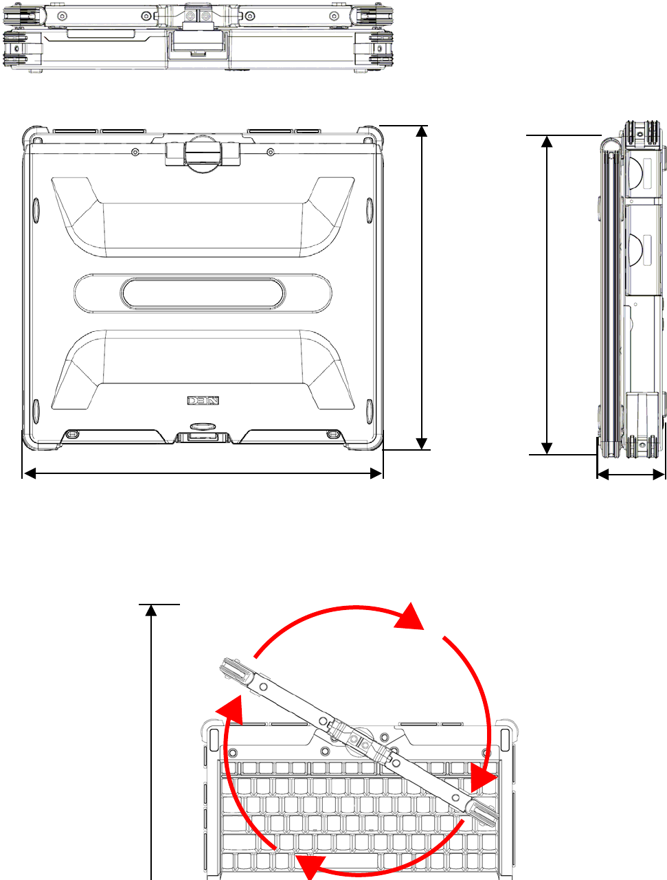
9.2 OUTSIDE DIMENSION
9.2.1 FC-N21S
(1) Body
ing projections and bumper)
267
246
lud(255 exc
296
(284 excluding projections and bumper)
53
(48 excluding projections
and bumper)
[Rotation of LCD display panel]
393.2
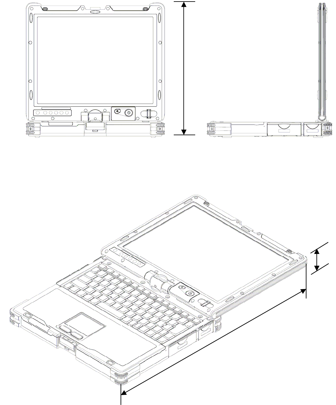
[Body with LCD display panel made upright (node type)]
288.0
[Body with LCD display panel taken down]
53
490.3
* Excluding projections (including rubber feet and protect rubbers at 4 corners)
Unit: mm
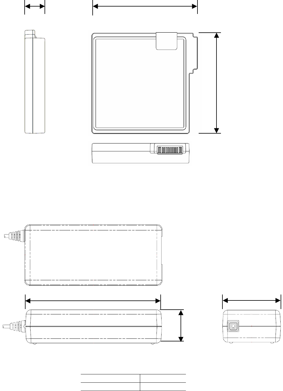
9.2.2 Spare Battery FC-N011
Unit: mm
Weight: about 0.33 kg
9.2.3 AC Adapter FC-N012
19.3 100.7
95.7
28.0 ±0.5
115.4 ±0.5 51.0
±
0.5
* Excluding projections
Unit: mm
Weight: about 0.46 kg
AC cable length About 1.8 m
About 2 m Power cord length
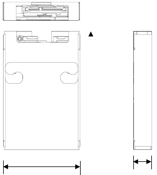
9.2.4 Hard Disk Drive FC-HD60KN
77.7 18.65
120.7
Unit: mm
Weight: about 0.12 kg