NEC FC-N22A Computer FC-NOTE Series User Manual
NEC Corporation Computer FC-NOTE Series
UserManual.wiki
>
NEC
>
FC N22A User Manual
User Manual
Navigation menu
Upload a User Manual
Namespaces
Wiki Guide
HTML
PDF
Info
Views
User Manual
Discussion / Help
Navigation

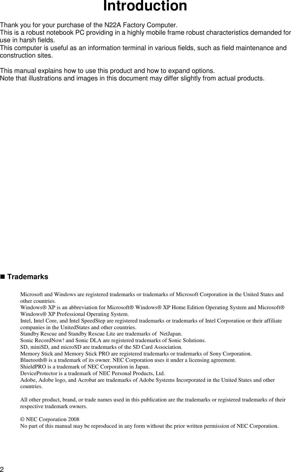
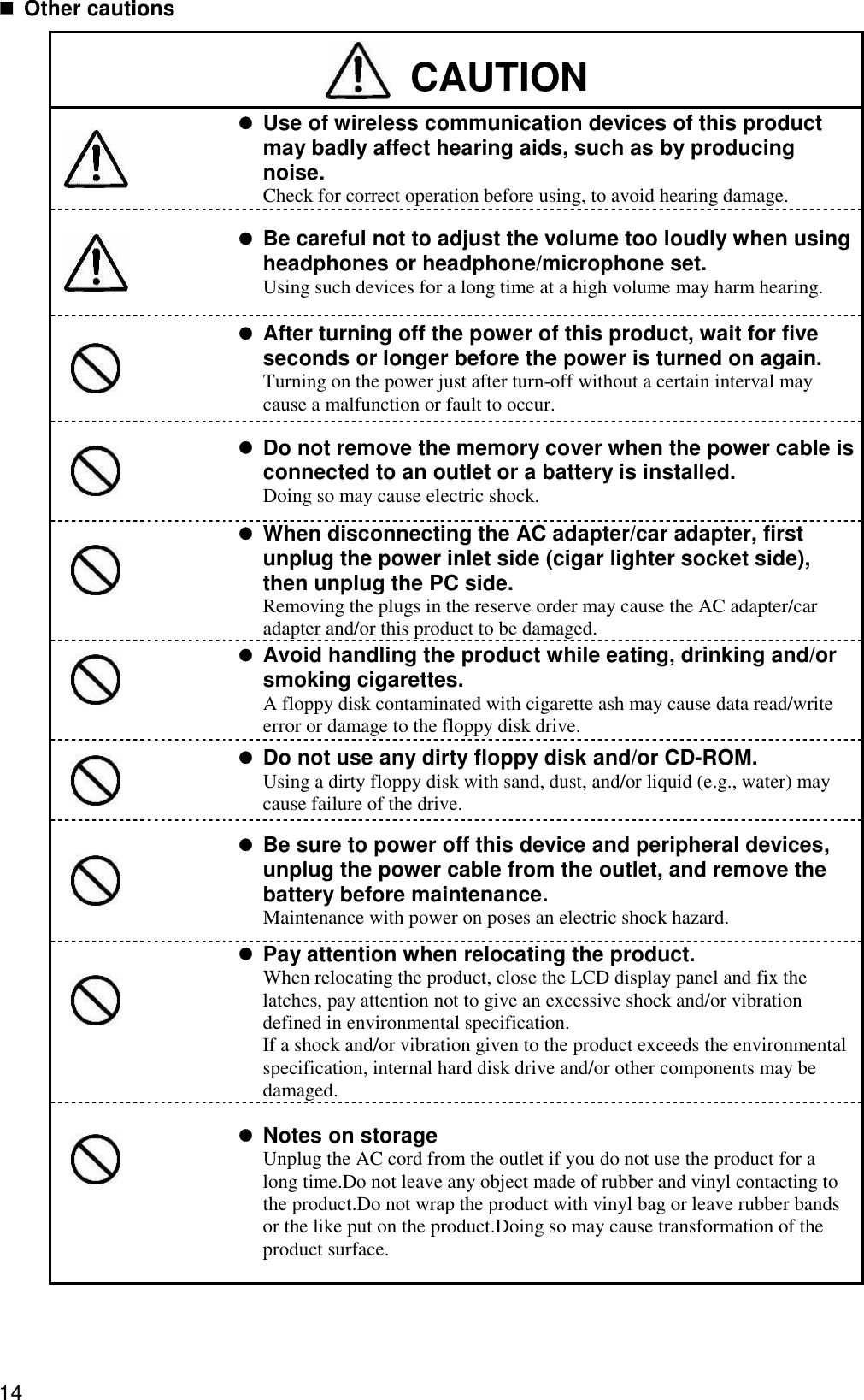
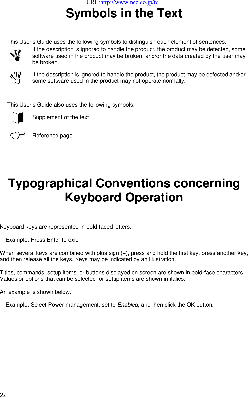

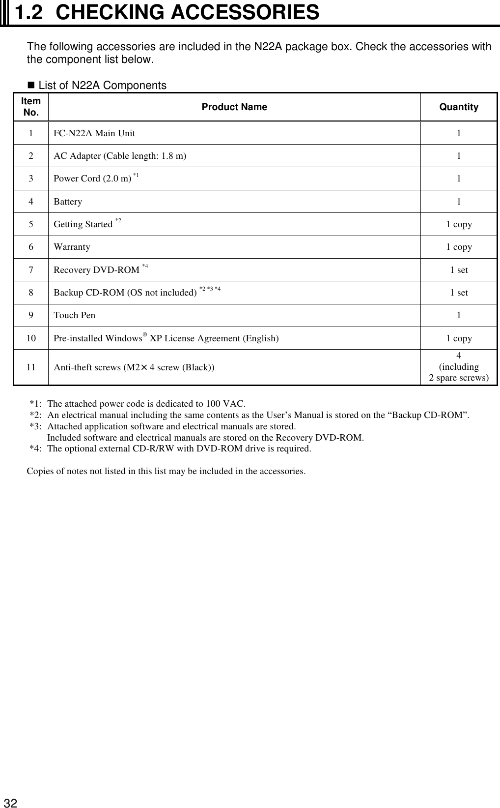
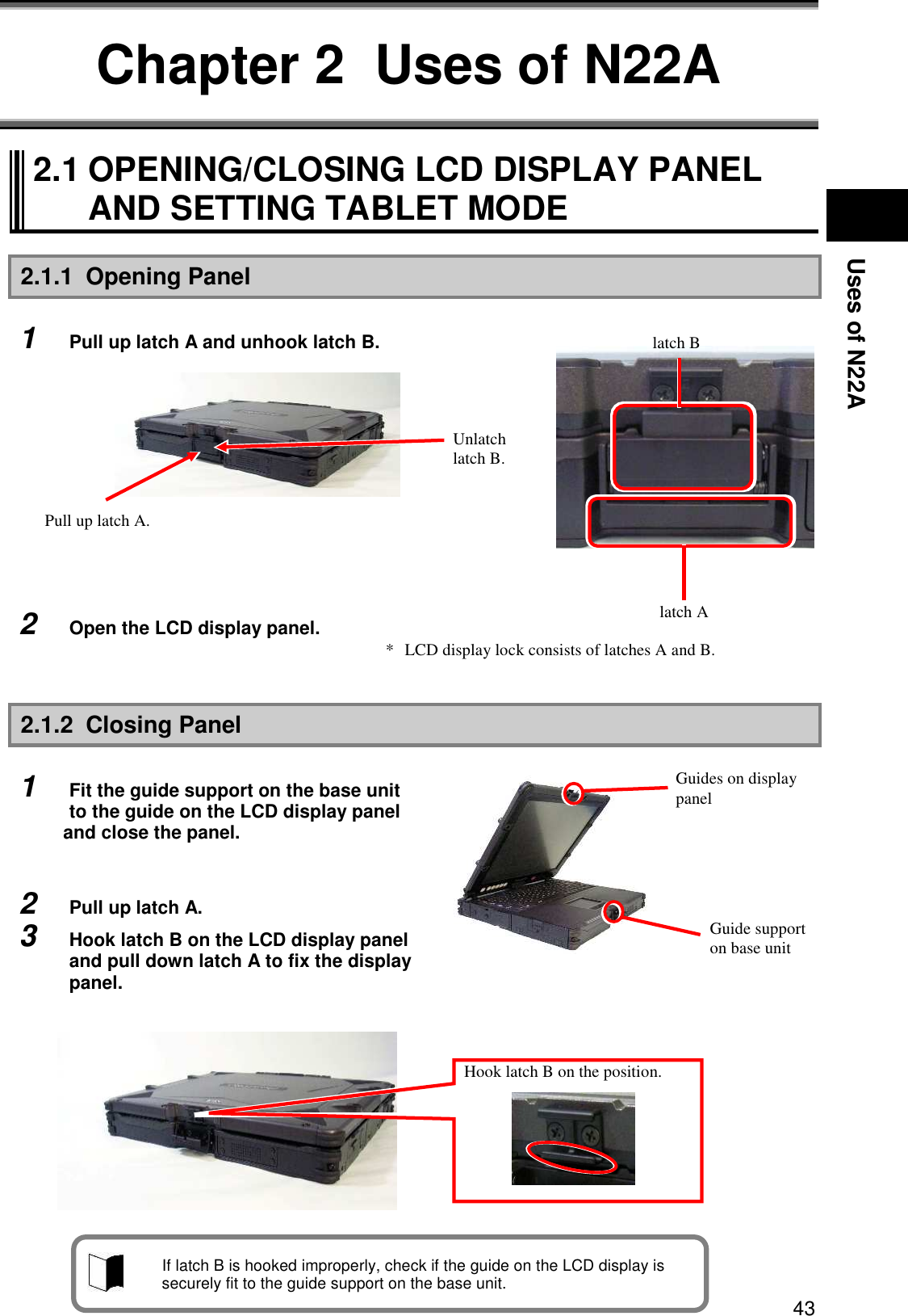
![27 PREPARATION Chapter 1 SYSTEM OVERVIEW AND PREPARATION 1.1 SPECIFICATIONS 1.1.1 Hardware Specification Item N22A(Note 1) CPU (Note 2) Intel®CoreTM2Duo processor Ultra low voltage version U7500 (Extended Intel SpeedStep® technology (Note 3) installed [1.06 GHz]) Primary 32KB for instruction/32KB for data (built in CPU) Cache memory Secondary 2.048KB (built in CPU) System bus 533 MHz (memory bus: 533 MHz) Chip set Mobile Intel 965GM Express chip set ICH8-M Security chip (Note 4) Conforming to TPM V.1.2 Memory (Note 5) 4GB max. (Note 6) 2 SO-DIMM slots DDR2-SDRAM (PC2-4200 (DDR2-533)) 12.1-in. TFT color LCD display (XGA) with touch panel (Note 8) Display element (Note 7) Stuck pixels of LCD (Note 9) 0.0003% or less Graphic accelerator Built in mobile Intel 965GM Express chip set (Dual display (Note 10), smoothing, and screen rotation features available) Video RAM 348MB max. (use of main memory) Display feature Resolution and display colors LCD: 1024×768 dots (16.77 million colors (Note 11)) External monitor: 1600×1200 dots max. (Note 12) (16.77 million colors (Note 11)) Floppy disk drive [Option] FC-FD002U connectable (USB connection) CD-ROM type drive [Option] FC-CW002U connectable (USB connection) Fixed disk drive (Note 14) [Selectable item] 80GB (Serial ATA specification) or 40GB (wide temperature range and Ultra ATA specification) Auxiliary storage (Note 13) Silicon disk drive (Note14) [Selectable item] 20GB (Ultra ATA specification) Keyboard (Note 15) [Selectable item] Standard or backlight keyboard English keyboard Key pitch: 17.55 mm Key stroke: 2.4 mm(backlight keyboard : 2.0mm) Pointing device Touch pad Input device Tablet button Desired functions can be assigned (up to 10) USB (Note 16) 3 ports (including 1 connect/disconnect-proof enhanced port), USB2.0 compatible Serial 1 D-sub 9-pin connector of 115,200 bps max. (male) Display Mini D-sub 15-pin connector (female) (for analog RGB monitor) Built-in LAN 1 RJ45 (1000BASE-T / 100BASE-TX / 10BASE-T) LAN connector Network Wireless LAN [Selectable item] Conforming to IEEE802.11a/b/g (Note 17) WEP [encryption key length: 64/128 bits (user setting key length: 40/104 bits)], WPA-PSK (TKIP/AES) and WPA2-PSK (AES) compatible Interface (Note 13) Sound feature Built-in PCM record/replay feature and monaural speaker Microphone input (stereo, mini jack) and output common to headphone/line (stereo, mini jack)](https://usermanual.wiki/NEC/FC-N22A/User-Guide-987184-Page-27.png)
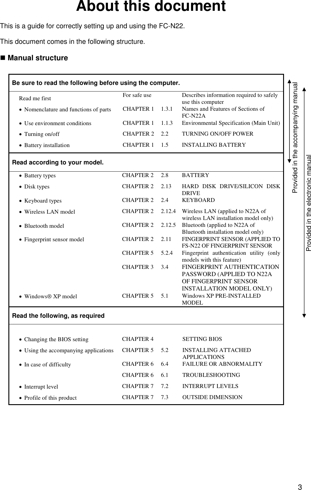
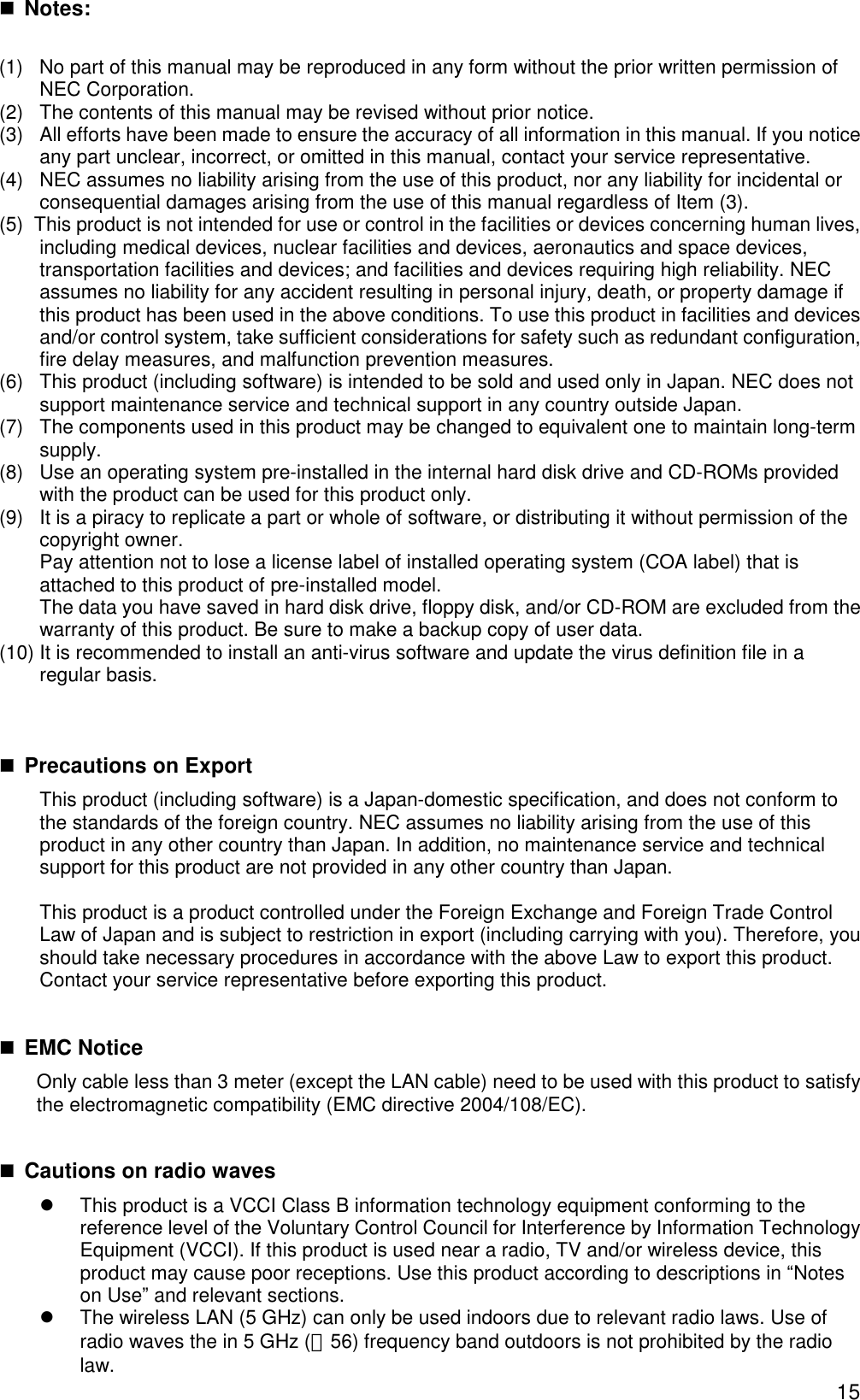
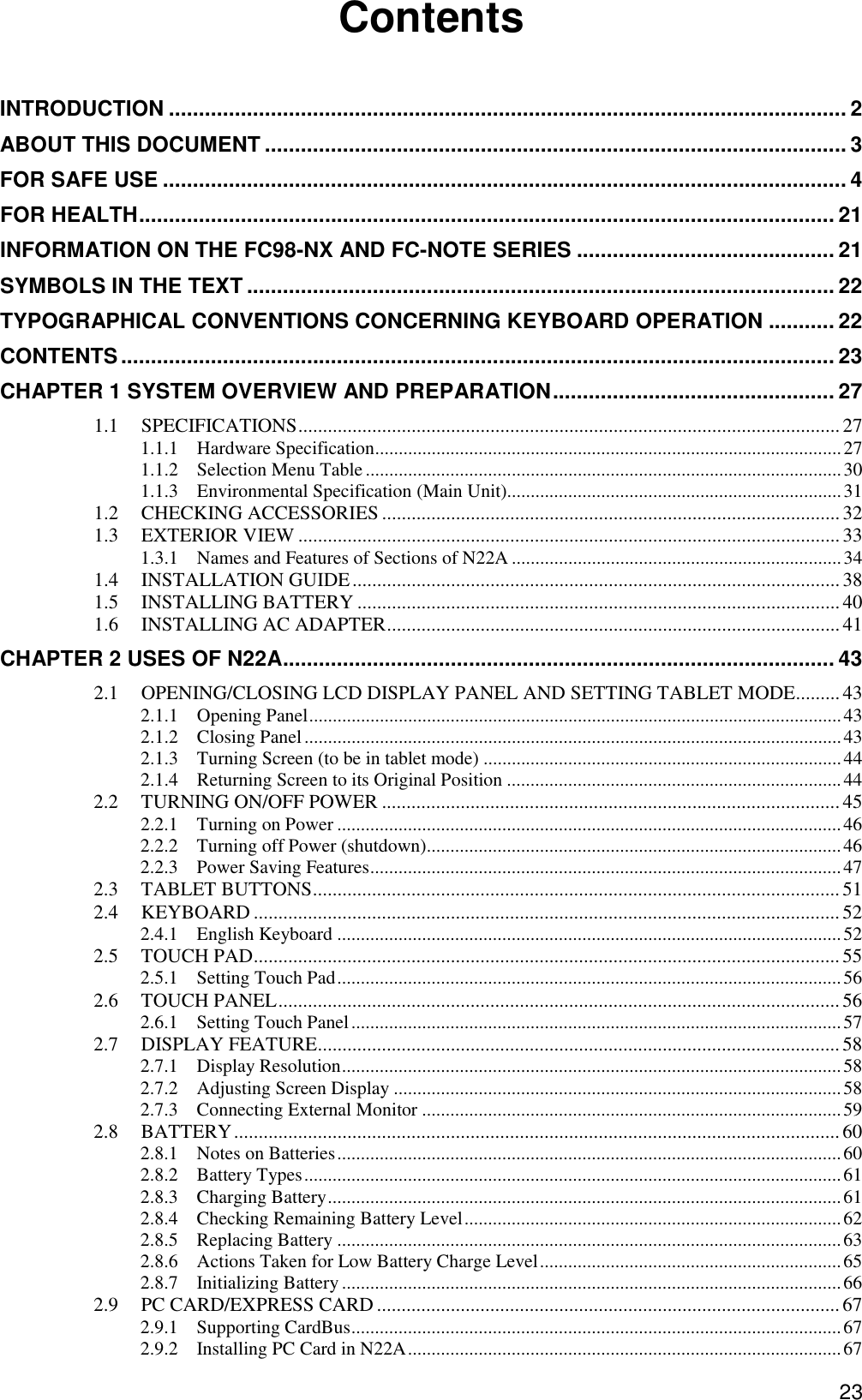
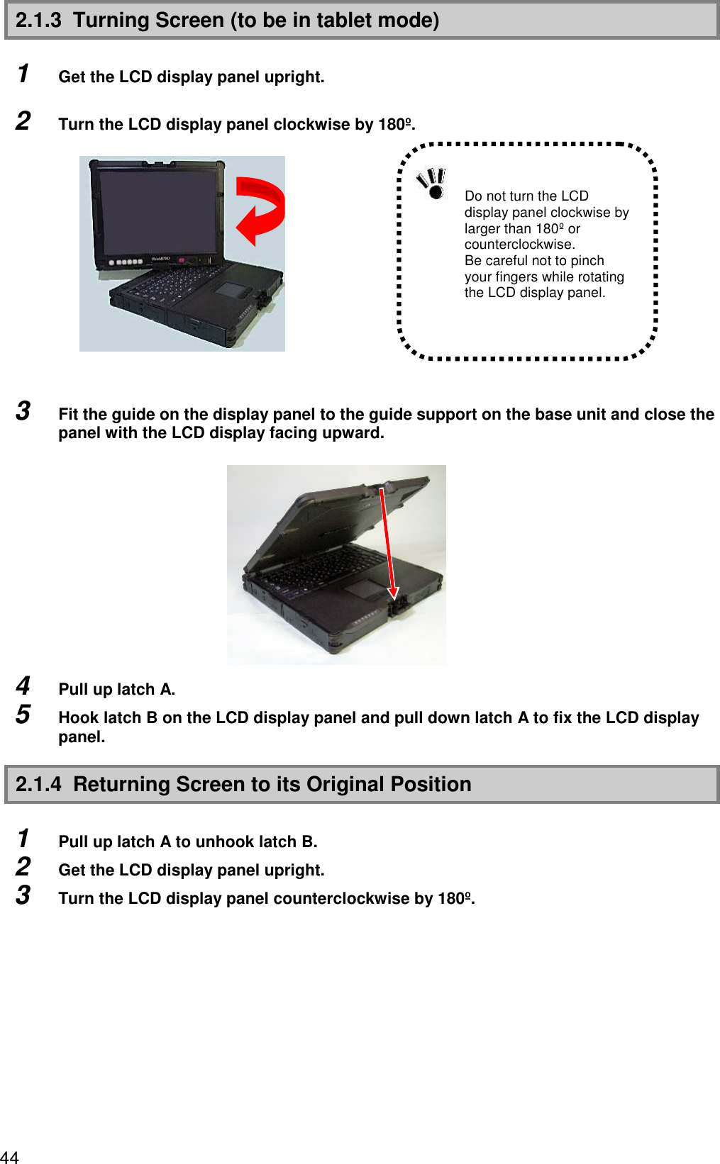
![28 Item N22A(Note 1) PC card slot (Notes 13 and 18) 1 Type I/II slot (Type III unavailable) conforming to PC Card Standard and compatible with CardBus Express card slot (Note 13 and 18) ExpressCard/34 · /54×1 slot Triple memory slot (Note 13 and 18) 1slot Security feature Security software normally attached (Note 19) Finger print sensor (Note 8) [Selectable item] Built-in type (line type) Authentication by fingerprint at OS logon or release of screen saver Power management Automatic or arbitrary settings enabled (including CPU control (Note 2), hard disk control, monitor power saving, suspend (standby) feature and hibernation) This machine Operating voltage: 16 V±5% Battery (Notes 20 and 21) [Selectable item] Standard type: driving period - 8 hours, charging time (in power-on/off states) - about 3.5 hours/8 hours and weight: about 0.4 kg Wide temperature range type: driving period - 6 hours, charging time (in power-on/off states) - about 4 hours/8 hours and weight: about 0.5 kg Stamina standard type: driving period - 12 hours, charging time (in power-on/off states) - about 4 hours/8 hours and weight: about 0.5 kg AC adapter 100 to 240 VAC ±10%, 50/60 Hz [A specific cord is required if used in another country other than Japan.] Power supply Car adapter [Option] FC-VA01N connectable ( DC12 to 24V , 7.5A ) Conforming standard Suitable to RoHS direct and conforming to VCCI Class B/FCC. Designed based on EMC direct (EN55022 and EN61000-6-2) (Note 22) and low voltage direct (EN60950-1) (Note 22) standards. Power design based on standard UL60950-1 Power consumption About 15 W (about 50 W max.) Energy efficiency (Power saving achievement rate) Target year: 2007 (Note 23), I division 0.0020 (A) Outside dimension 290(W) × 255(D) × 47(H) mm (excluding projections and bumper) Weight About 2.5 kg (including standard battery) Installed OS [Selectable item] Microsoft Windows XP Professional (Service Pack 2) Japanese / English 1: See “Selection Menu Table” for type names and numbers. 2: N22A includes a control feature enabling the CPU to operate dynamically depending on use environments and loads. 3: In any OS environment other than preinstalled OS environment, the expanded IntelSpeedStep feature may be unavailable. 4: The security chip is unavailable to any OS other than preinstalled Windows XP Professional. 5: The capacity of a memory board can be selected out of 512MB, 1GB, 2GB, and 4GB on the selection menu. 6: Replacement of an expanded RAM board is enabled only on a single slot. The maximum memory capacity can be installed if memory of 2GB or larger is selected. If memory of less than 2GB is selected, the maximum memory capacity is “selected memory capacity” + 2GB. 7: The LCD display is manufactured based on extremely high-precise technology. However, dot drops (such as negligible black points and red, blue or green points always illuminating) may appear on a part of the screen. In addition, color and/or brightness irregularities may appear depending on view angles. These are caused by characteristics of LCD displays and do not indicate any defects. 8: The touch panel is unavailable under USB locking. 9: The base dot drop rate is calculated in sub-pixels according to the standard of ISO13406-2. See http://www.express.nec.co.jp/products/pc/lcddot.html for details.(As of May 2008) 10: The feature allows an external display for desktop screen to be different from the LCD display of N22A. 11: 16.77 million color display is accomplished by the dithering feature of graphic accelerator. 12: N22A has the resolution and the number of colors. However, N22A cannot realize them depending on the resolution and refresh rate of the connected display. The LCD display on N22A and the external display connected to N22A can display the same screen. However, if the enlarged display feature is not used, display data may not extend to all over the external display.](https://usermanual.wiki/NEC/FC-N22A/User-Guide-987184-Page-28.png)

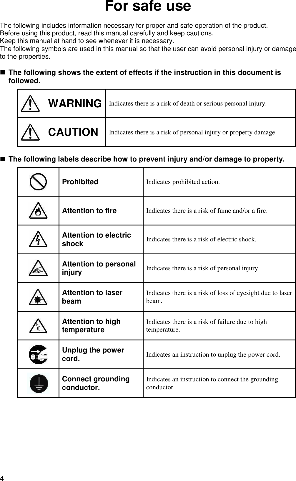
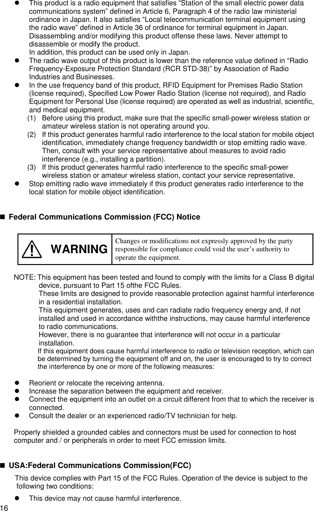
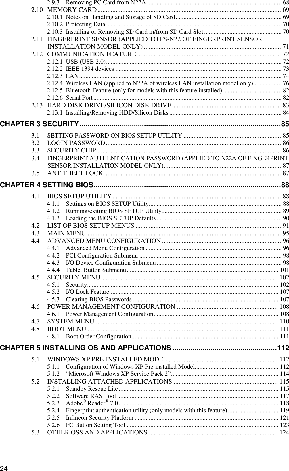
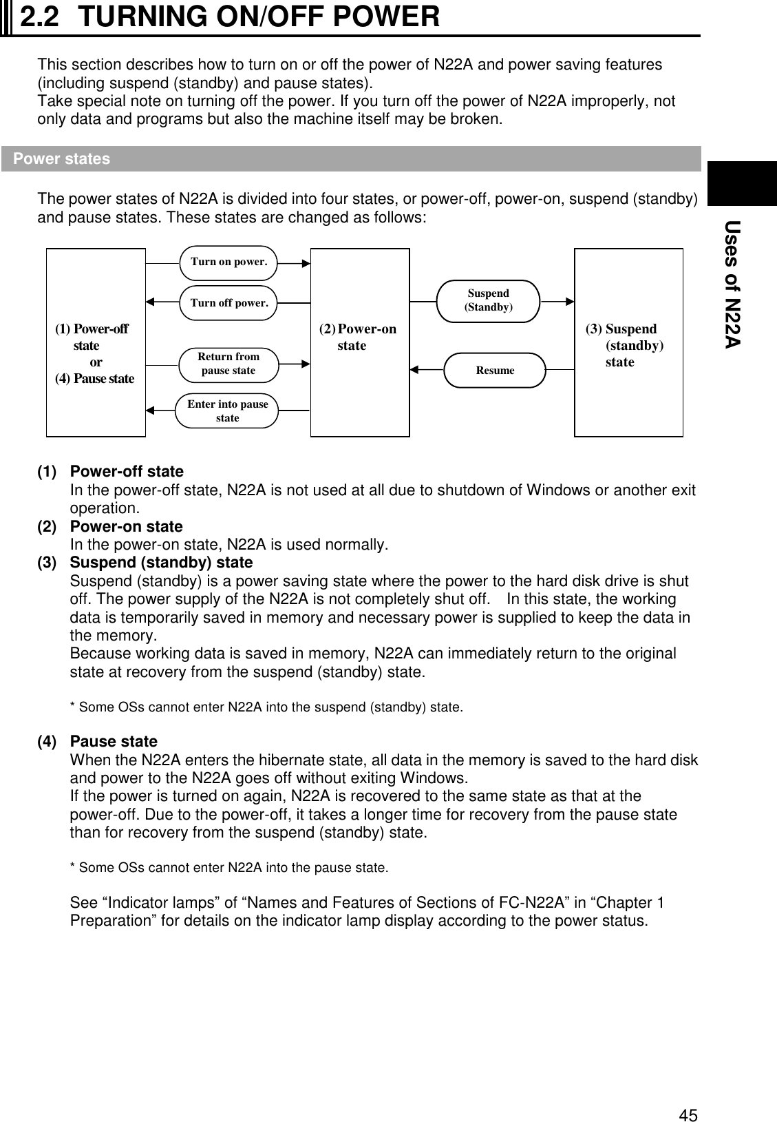
![30 1.1.2 Selection Menu Table Windows XP pre-installed model Series title Selection menu Base unit Keyboard OS Memory capacity Disk drive and battery Wireless LAN and fingerprint authentication [B] Standard Japanese keyboard [X] Windows XP Professional (Service Pack2) Japanese ver. preinstalled [3] 512MB (512MB × 1) [S] Standard HDD × 1 (SerialATA spec., 80GB) Standard battery [B] Wireless LAN: No Fingerprint authentication: No Bluetooth: Yes [C] Backlight Japanese keyboard [Y] Windows XP Professional (Service Pack2) English ver. preinstalled (Note 1) [4] 1GB (1GB × 1) [T] Standard HDD × 1 (SerialATA spec., 80GB) Stamina standard battery [F] Wireless LAN: No Fingerprint authentication: Yes Bluetooth: No [G] Standard keyboard [6] 2GB (2GB × 1) [W] Wide temperature range HDD × 1 (UltraATA spec., 40GB) Wide temperature range battery [S] Wireless LAN: Yes Fingerprint authentication: No Bluetooth:Yes [H] Backlight keyboard [F] Silicon disk × 1 (UltraATA spec., 20GB) Stamina battery [W] Wireless LAN: Yes Fingerprint authentication: Yes Bluetooth: Yes N22A CPU Windows® XP Preinstalled model Intel®CoreTM2Duo processor Ultra low voltage version U7500(1.06GHz) Memory (3 slots) PC card (1 slot) SD card (1 slot) Express card × 1 slot [H] Silicon disk × 1 (UltraATA spec., 20GB) Wide temperature range battery [Z] Wireless LAN: No Fingerprint authentication: No Bluetooth: No 1: If Windows® XP Professional (Service Pack 2) English version preinstalled is selected, the product will be shipped with an English keyboard. * The part and generation numbers of N22A are directed on the nameplate and warranty at shipment. See the NEC web site for details of the generation numbers. Ex.: For order number FC-N22A/BX2SS, the notation on the nameplate and warranty is FC-N22A/BX2SS** (**: generation number). * N22A of Windows XP pre-installed model already has Microsoft Windows XP Professional Operating System (Service Pack 2) installed. Note that deleting and down-grading of Service Pack is disabled. First partition: 20GB (NTFS) (Software already installed at shipment occupies about 5GB in the first partition.) Second partition: Remaining memory (NTFS) Part name Model name Part number](https://usermanual.wiki/NEC/FC-N22A/User-Guide-987184-Page-30.png)
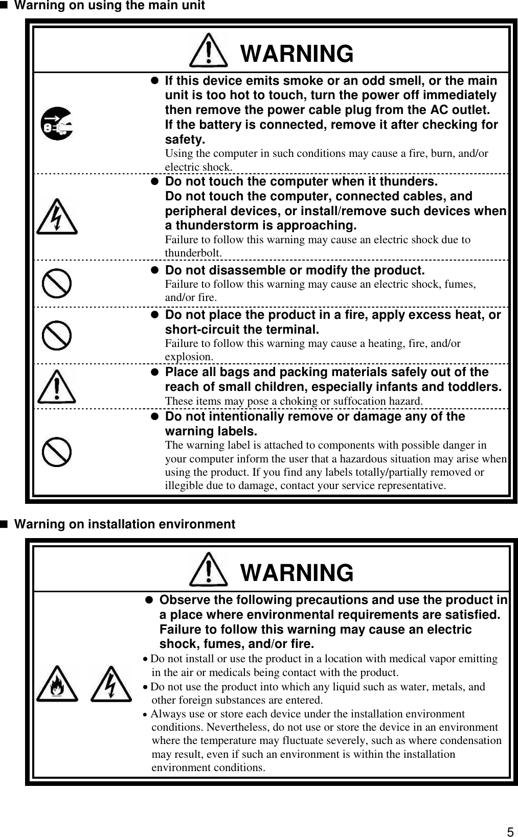
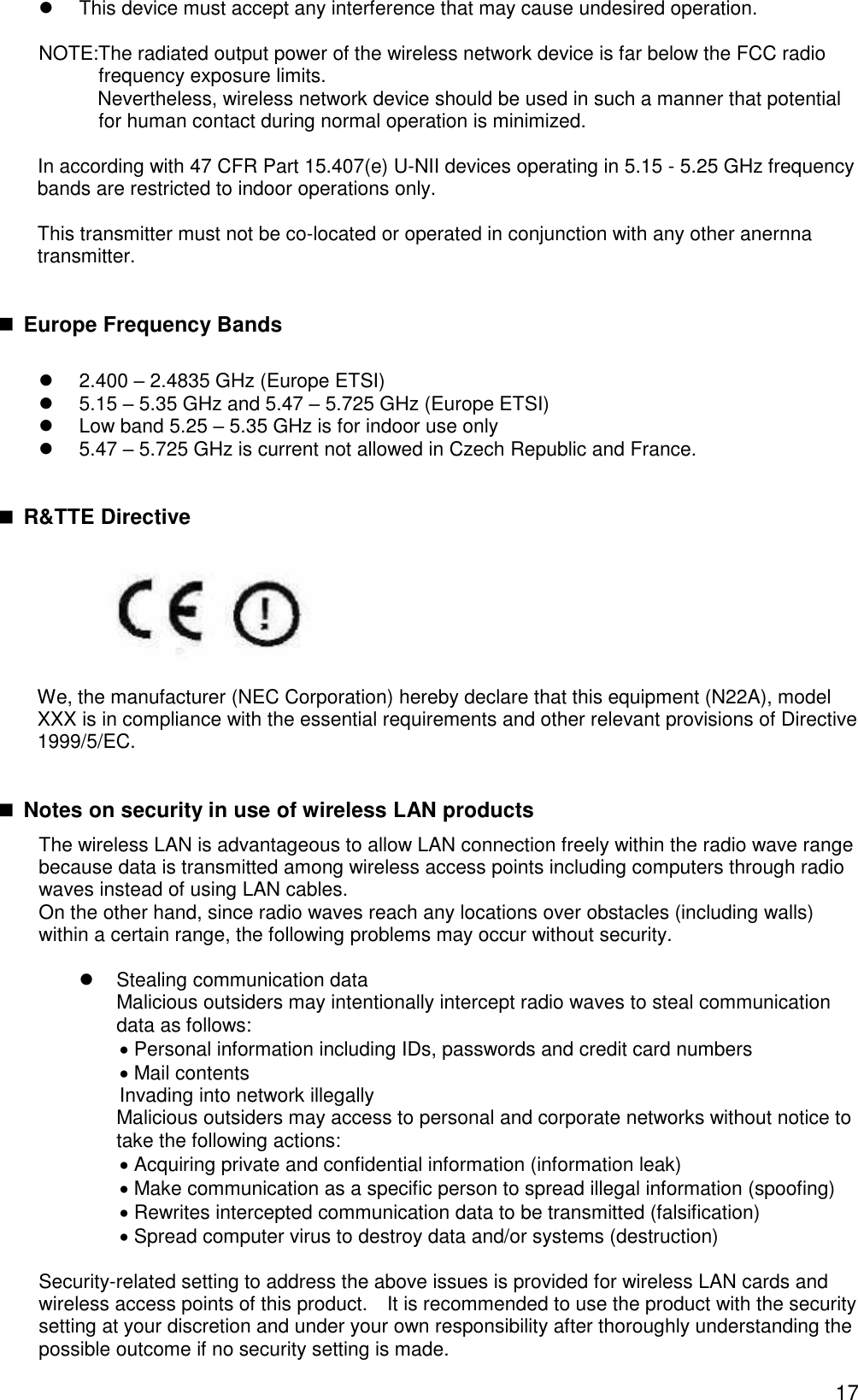
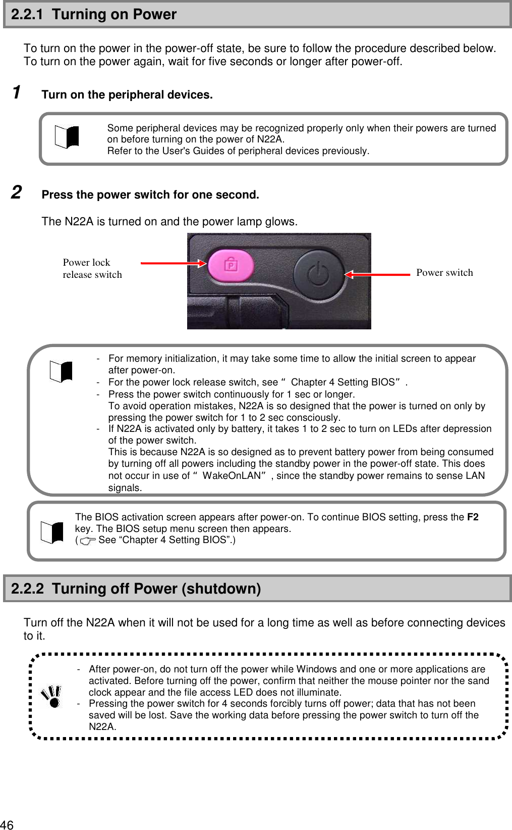
![31 1.1.3 Environmental Specification (Main Unit) Item Condition Installation of standard hard disk drive and battery Installation of silicon disk drive and standard battery Installation of silicon disk drive and stamina standard battery Installation of hard disk drive and battery of wide temperature range Operating 5 to 45 ºC (Note 2) -20 to 50ºC (Note 2) Storage -40 to 70ºC Temperature Evaluation standard IEC 68-2-1,2,14 / MIL-STD-810F, Method 501.4, 502.4 Operating 5 to 95% RH (without condensation) Storage 5 to 95% RH (without condensation) Humidity Evaluation standard IEC 68-2-30 / MIL-STD-810F, Method 507.4 Operating 15,000 ft (4,572m) Storage 40,000 ft (12,190m) Change rate 2,000 ft/min (609.6 m/min) Altitude Evaluation standard IEC 68-2-13 / MIL-STD-810F, Method 500.4 Operating 147 m/s2, 11 ms, half sinusoidal wave Storage 490 m/s2, 11 ms, half sinusoidal wave Shock resistance (Note 1) Evaluation standard IEC 68-2-27 / MIL-STD-810F, Method 516.5 Operating [Sinusoidal wave] 0.075 mm (0-P) in frequency range 10 to 55 Hz 9.8 m/s2 (0-P) in frequency range 55 to 500 Hz Storage [Sinusoidal wave] 0.15 mm (0-P) in frequency range 10 to 55 Hz 19.6 m/s2 (0-P) in frequency range 55 to 500 Hz [Random wave] 0.04G2/Hz in frequency range 20 to 1000 Hz -6 dB/Octave in frequency range 1000 to 2000 Hz Operating Sinusoidal wave: IEC68-2-6 Vibration resistance (Note 1) Evaluation standard Storage Sinusoidal wave: IEC68-2-6 Random wave: MIL-STD-810F, Method 514.5 Category 24 FIGURE 514.5C-17 Operating IP54 Storage IP54 Dust proof and drip proof Evaluation standard IEC 529 / MIL-STD-810F IEC: Abbreviation for International Electrotechnical Commission. MIL: Abbreviation for Military Specifications and Standards. Note 1: The vibration resistance of N22A does not assure that it has sufficient strength against resonance generated when the frequency of added vibration is close to the natural frequency of N22A. Note 2: Use the product with an ambient temperature of from 5ºC to 40ºC in tablet mode or while the battery is being charged. * The specification does not assure that N22A can operate continuously under the described environmental conditions in which N22A is installed. In addition, if N22A is equipped with one or more NEC or commercial options, the most severe environmental condition among those for N22A and the options is applied. Installation environment conditions for external optional devices are different that those for the main unit, see the document that comes with each device for detailed conditions. When N22A is stored at high/low temperatures, the clock built in N22A may be shifted. Set the clock before N22A is used again.](https://usermanual.wiki/NEC/FC-N22A/User-Guide-987184-Page-31.png)

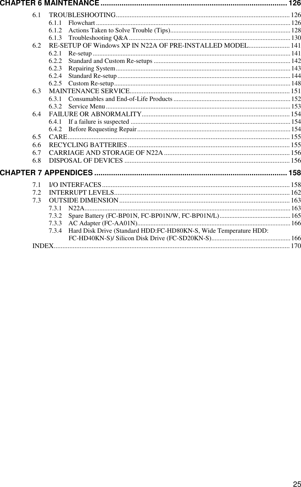
![35 (2) Outside sections (11) (12) (1) (2) (4) (5) (18) [Right side view] [Front view] [Bottom view] [Rear view] (6) (13) (3) (10) (7) (9) (19) [Left side view] (8) (14) (15) (16) (17)](https://usermanual.wiki/NEC/FC-N22A/User-Guide-987184-Page-35.png)

![47 Uses of N22A Power-off procedure by using Windows End menu 1 Save edited data and quit all the applications. 2 On the Windows® XP screen, click [Start] [Shutdown]. Next, click the [Shutdown] button. Do not press the power switch during the shutdown processing. 3 Check that the power is turned off. After a few seconds, the screen will go dark and the power will turn off automatically. Check that the power lamp goes off. 4 Turn off the peripheral devices. Power-off procedure by using power switch 1 Save edited data and quit all the applications. 2 Press the power switch. 3 Check that the power is turned off. 4 Turn off the peripheral devices. 2.2.3 Power Saving Features The suspend (standby) or hibernate features allow stopping of operation without exiting applications. When restored, different from shutting down, the screen immediately before the suspend (standby) or hibernate status is entered allows operation to be immediately started (resuming). Notes on using suspend (standby) and resume feature or hibernate status To use the suspend (standby) and resume features, note the following. Failure to follow these instructions may cause working data for entering N22A into the suspend (standby) state to be lost or not to be restored. Before entering suspend (standby) or hibernate status When any communication device is being used, quit the communication application before entering the suspend (standby) or hibernate status. Entering N22A into the suspend (standby) state under communication may leave the line connected to add up the communication fee. Note that entering the hibernate status while communication being performed may forcibly disconnect communication. Before N22A can be entered into the suspend (standby) state, USB devices should be removed from N22A. N22A with one or more USB devices connected may not be able to be entered into the suspend (standby) state.](https://usermanual.wiki/NEC/FC-N22A/User-Guide-987184-Page-47.png)
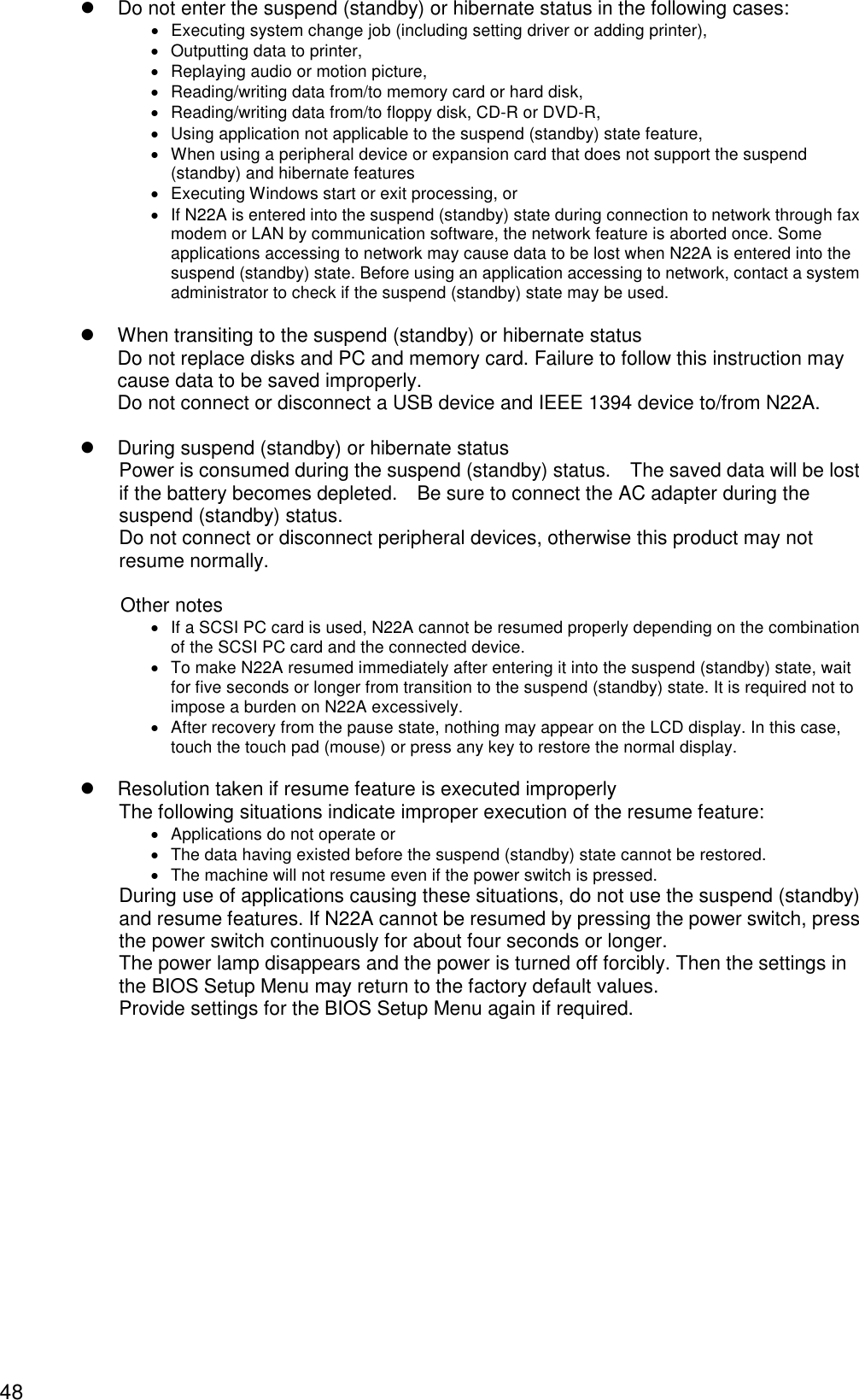
![49 Uses of N22A Setting power saving feature Perform power saving feature from [Power supply option] of Windows. Operation for manually executing the power saving feature and the time until the machine automatically enter the power saving mode can be set. (1) Changing operation to execute the power saving feature 1. Click [Start] [Control panel] [Performance and maintenance] [Power option] [Detailed settings] tab. 2. In the [Power button] field, set the operation and the power saving feature to be executed. When the power switch is pressed Select the power saving feature to be executed in [When the power switch of the computer is pressed]. When the LCD display is closed Select the power saving feature to be executed in [When the portable computer is closed]. 3. Click the [Apply] button, and then click the [OK] button. Suspend (standby) state If you want to suspend jobs on N22A temporarily, you can enter N22A into the suspend (standby) state to save power consumption. To suspend (standby) and then resume N22A with the power switch, the setting of the power switch must be changed. To enter N22A into the suspend (standby) state in the power-on state manually, follow either of the procedures below. (1) Entering the suspend (standby) status The following three methods are available. Entering suspend (standby) status from the Windows shutdown menu Click [Start] [Shutdown option], and then click [Standby]. Close the LCD display Enabled when [Standby] is selected in [When the portable computer is closed]. Press the power switch Press the power switch for about one second while the power is on. The power lamp blinks in green, indicating the suspend (standby) status. Enabled when [Standby] is selected in [When the power switch of the computer is pressed]. Before you can suspend (standby) and then resume N22A, wait for five seconds or longer after change of the power lamp status. Do not press the power switch for four seconds or longer to suspend (standby) or resume N22A. Pressing the power switch for four seconds or longer causes the power to be turned off forcibly, which results in erasing of unsaved data.](https://usermanual.wiki/NEC/FC-N22A/User-Guide-987184-Page-49.png)
![50 (2) Resuming from suspend (standby) status The following three methods are available. Press the power switch. The power lamp illuminates in green and N22A recovers from the suspend (standby) state (or resumes). Press any key Press any key Open the LCD display When the N22A has entered into the suspend (standby) status by closing the LCD display, open the LCD display to resume from the suspend (standby) status. Pause state If jobs on N22A are halted for a long period, entering N22A into the pause state allows power consumption to be saved. (1) Enabling hibernate status 1. Click [Start] [Control panel] [Performance and maintenance] [Power option]. 2. Click the [Hibernate status] tab, and then select “Enable hibernate status”. 3. Click [OK]. (2) Entering to hibernate status The following three methods are available. Enter the hibernate status from the Windows Shutdown menu. Click [Start] [Turn Off Computer]. Then press Shift and click [Hibernate]. Press the power switch Enabled when [hibernate] is selected in [When the power switch of the computer is pressed]. Close the LCD display Enabled when [hibernate] is selected in [When the portable computer is closed]. (3) Resuming from hibernate status The following two methods are available. Press the power switch. Windows is started to recover the state set when the power was turned off last by using the pause state feature. Open the LCD display When the N22A has entered into the hibernate status by closing the LCD display, open the LCD display to resume from the hibernate status. It may take time from closing the LCD display panel until the N22A enters the suspend (standby) status. When the time of closing the LCD display is too short, the N22A will not enter the suspend (standby) status. In this case, close the LCD display panel again. After recovery from the pause state, nothing may appear on the LCD display. If so, move the mouse or press any key on the keyboard to allow the display screen to appear properly.](https://usermanual.wiki/NEC/FC-N22A/User-Guide-987184-Page-50.png)
![51 Uses of N22A 2.3 TABLET BUTTONS These buttons enable direct execution of screen rotation, LCD brightness control, etc. Button assignment can be changed as required. (Tb) [Tb] button (1) Tablet button 1 (2) Tablet button 2 (3) Tablet button 3 (4) Tablet button 4 (5) Tablet button 5 (6) Label pasting area (1) Operations at depression of buttons Button Operation (defined at shipment) Tablet button 1 Ctrl + Alt + Del Tablet button 2 Rotates the Windows screen. Tablet button 3 Enter Tablet button 4 Increases brightness of the LCD screen. Tablet button 5 Decreases brightness of the LCD screen. [Tb] + Tablet button 1 Esc [Tb] + Tablet button 2 Tab [Tb] + Tablet button 3 Starts the screen keyboard. [Tb] + Tablet button 4 Moves the cursor upward. [Tb] + Tablet button 5 Moves the cursor downward. (2) Label pasting area When key assignment is changed, you can paste a label showing the new key assignment on the area. The possible label size is as follows. Prepare the label if required. Size: (3) Changing key assignment Button assignment can be changed from the BIOS setup menu. ( See “Tablet Button Submenu” in “Chapter 4 Setting BIOS.”) (4) Starting any application From the BIOS setup menu, assign [FC button 1] and [FC button 2] to enable execution of the commands (starting application) registered using the FC button setting tool. For FC button setting tool, see “FC Button Setting Tool” in “Chapter 5 Installing OS and Applications.” (6) 3mm 60mm (Tb) (1) (2) (3) (5) (4)](https://usermanual.wiki/NEC/FC-N22A/User-Guide-987184-Page-51.png)
![52 2.4 KEYBOARD 2.4.1 English Keyboard Using Hot Keys [Fn] Combining Fn with another key allows various operations on N22A to be done easily. These are called hot key features. Some icons indicating the features resulting from combinations of respective keys with Fn are printed on the keys with the same color as Fn. The table below lists the hot keys and their features. Key combination Feature or description Fn+F1 Switches the keyboard backlight from off to on (8 levels). (only for backlight keyboard). dark bright OFF Note: Switches only between on and off when the keyboard backlight control is set to [Interlocked] in the BIOS setting. Fn+F2 Switches the ON/OFF status of the wireless LAN feature. (The external switch is on.) Fn+F3 Changes the display mode to any of the following three modes if an external monitor is connected to N22A. (for only Windows XP) LCD External monitor Display on both monitors Note: Alternatives may be limited to “External monitor” and “Display on both monitors”, depending on the OS used. Fn+F4 Turns off the backlight of the LCD display. Fn+F5 Switches enlarged display/no enlarged display of the screen in the low resolution mode. Some operating systems do not support this feature. Fn+F6 Disable computer sound (Mute Status) Fn+F7 Raises the brightness of the LCD display. Fn+F8 Lowers the brightness of the LCD display. Fn+F9 Raises the volume of the speakers. Fn+F10 Lowers the volume of the speakers. Fn+F11 Switches scroll lock on/off. Fn+1 Fn+2 FC button Allows registered application to be started (see Chapter 5). Fn+PrtScr (Sys Rq) System request 8 levels ⑤](https://usermanual.wiki/NEC/FC-N22A/User-Guide-987184-Page-52.png)
![53 Uses of N22A Key combination Feature or description Fn+ScrLK (Num Lk) Numeric lock If these keys are pressed once, the lamp goes on and blue numerals and symbols on keys are enabled. If the keys are pressed again, the lamp goes off and normal characters are enabled. Fn+Pause (Break) Break Fn+ (Page Up) Page Up Fn+ (Page Dn) Page Dn Fn+ (Home) Home Fn+ (End) End Fn+Alt Right Alt Fn+ Right Windows Keyboard with backlight If a keyboard with backlight is selected from the selection menu, a Japanese keyboard with backlight is installed. It is suitable for use in a dark place such as a warehouse or at night. Backlight brightness can be adjusted in 8 levels or off by pressing Fn + F1. It is set to off by default. In the [Details] menu of the BIOS settings, set [Keyboard backlight control] to [Interlocked] to adjust the backlight and LCD brightness at the same time. It is set to [Interlocked] by default. In this case, press Fn + F7 to increase brightness, or press Fn + F8 to decrease brightness. Press Fn + F4 to set to “off”. Keyboard backlight automatically turns off at any of the following events: When the LCD display panel is closed (opening it resumes the previous status) When entered into the suspend (standby) status (the previous status resumes by keyboard or mouse operation) When entered into the hibernate status (pressing the power switch resumes the previous status) The keyboard backlight does not automatically turn off during any of the following events: When “LCD power off” is set for Power supply option. When screen saver is being executed. Press Fn + F1 to turn off the keyboard backlight. Some OSs and software may disable a part of hot keys to be used.](https://usermanual.wiki/NEC/FC-N22A/User-Guide-987184-Page-53.png)
![54 Entering the euro symbol To enter the euro symbol (€) printed on the 5, change the keyboard layout as described below. 1 Click [Start] [Control Panel]. 2 Click [Date, Time, Language, and Regional Option]. 3 Click the [Details] button under “Text services and input languages” on the [Languages] tab. Note: When the desired keyboard exists in the installed service list, proceed to step 8. Click the [Add] button under “Installed service”. 4 Select “English (United State)” in the “Input language” list. 5 Select “United States-International” in the “Keyboard layout/IME” list. 6 Click the [OK] button. 7 Select “English (United States)-United States-International” for “Default input language”. 8 Click the [OK] button. 9 Restart the N22A. The above settings allow entering the euro symbol (€) by pressing Ctrl + Alt + 5.](https://usermanual.wiki/NEC/FC-N22A/User-Guide-987184-Page-54.png)
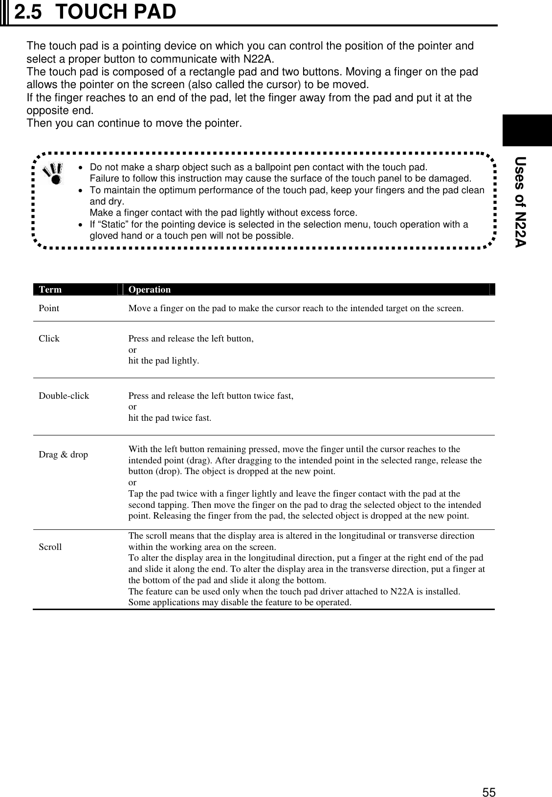
![56 2.5.1 Setting Touch Pad Settings of the touch pad can be changed depending on user needs. For example, left-handed users can interchange the features of the left and right buttons to use the left and right buttons as the right and left buttons in the normal state, respectively. In addition, the size and speed of the pointer on the screen may be changed. 1 Display the setting screen. Click [Start] [Control Panel] [Printers and Other Hardware] [Mouse]. Then the [Mouse Properties] dialog box appears. 2 Perform settings. Perform settings on each of the [Buttons], [Pointers], and [Pointer Options] tabs. 3 Click [Apply] and then click [OK]. 2.6 TOUCH PANEL The touch panel feature allows the same operation as the touch pad on the LCD display. Use the provided touch pen to perform operation on the display. Term Operation Point Slide the pen or finger on the touch panel until the cursor reaches to the intended target on the screen. Click Tap a point on the touch panel lightly. Double-click Tap the touch panel twice fast. Drag & drop Press the touch panel with the pen or finger lightly and slide the pen or finger to the intended point (drag). After dragging to the intended point in the selected range, release the pen or finger (drop). The object is dropped at the new point. If the left and right buttons on the touch pad are interchanged, tapping the touch panel cannot substitute for pressing the left button. The features of the touch pad can be enabled/disabled by changing some BIOS settings. Do not make a sharp object such as a ballpoint pen or a pencil contact with the touch panel. Failure to follow this instruction may cause the touch panel to be damaged. If the surface of the touch panel is dirt, wipe the surface with a dry and soft cloth such as a glass wiping cloth. If manipulating the touch panel with dust adhering on the surface may cause the surface to be hurt. Neither put your hands on the surface of the touch panel nor push the surrounding of the touch panel hard. The pointer (cursor) may not be operated normally or moved to an end of the screen. While the touch panel is manipulated, do not put your hands on the keyboard. Failure to follow this instruction may cause key entries to occur.](https://usermanual.wiki/NEC/FC-N22A/User-Guide-987184-Page-56.png)
![57 Uses of N22A 2.6.1 Setting Touch Panel Setting features You can change the size and speed of the pointer on the screen. For settings, see “Setting Touch Pad.” Compensating position The position of pointer must be compensated in the following cases: Changing the resolution of the screen is changed, or The pointer is not moved properly to the point with which you make the touch pen contact. Compensate the point of the pointer in the following procedure: 1 Display the setting screen. Click [Start] [All Programs] [Gunze TPDD] [Calibrate]. 2 Click the four sides specified with red mark × on the screen with the touch pen for calibration. Settings on the touch pad are also applied to the touch panel. The touch panel cannot be independent of the touch pad.](https://usermanual.wiki/NEC/FC-N22A/User-Guide-987184-Page-57.png)
![58 2.7 DISPLAY FEATURE The display features of N22A are characterized as follows: 12.1-in. TFT (Thin-Film Transistor) color LCD display of resolution 1024×768 XGA (Extended Video Graphics Array) Concurrent display of both LCD display and external monitor 2.7.1 Display Resolution The default resolution and the default number of colors are set at shipment of N22A. For display of a higher resolution, N22A can connect with an external monitor supporting the higher resolution. The table below shows the display modes available to N22A. Display mode LCD display only Resolution Number of colors 16 bits 800 600 32 bits 16 bits 1024 768 32 bits * N22A allows external monitors can have resolutions in the range from 640×480 to 1600×1200 and the number of colors of 8, 16 and/or 32 bits. However, the used external monitor limits available resolutions and the available number of colors. Notes on color: 8 bits = 256 colors 16 bits = High Color or 65,536 (64 K) colors 32 bits = True Color 16,770,000 (16 M) colors (16.77 million color display is accomplished by the dithering feature of the graphic accelerator.) 2.7.2 Adjusting Screen Display To change the resolution or the number of colors of the screen, follow the procedure below: 1 Open the setting screen. Click [Start] [Control Panel] [Appearance and Themes] [Display]. Then the [Display Properties] dialog box appears. 2 Select the [Settings] tab to set the resolution and/or the number of colors of the screen. 3 Click [Apply] then click [OK]. Some OSs may limit display modes. To enable the virtual screen feature, follow the procedure below: On the screen displayed by selecting the [Settings] tab, click the [Advanced] button. Click the [Monitor] tab. Click [Hide modes that this monitor cannot display] to uncheck it. Click [OK].](https://usermanual.wiki/NEC/FC-N22A/User-Guide-987184-Page-58.png)
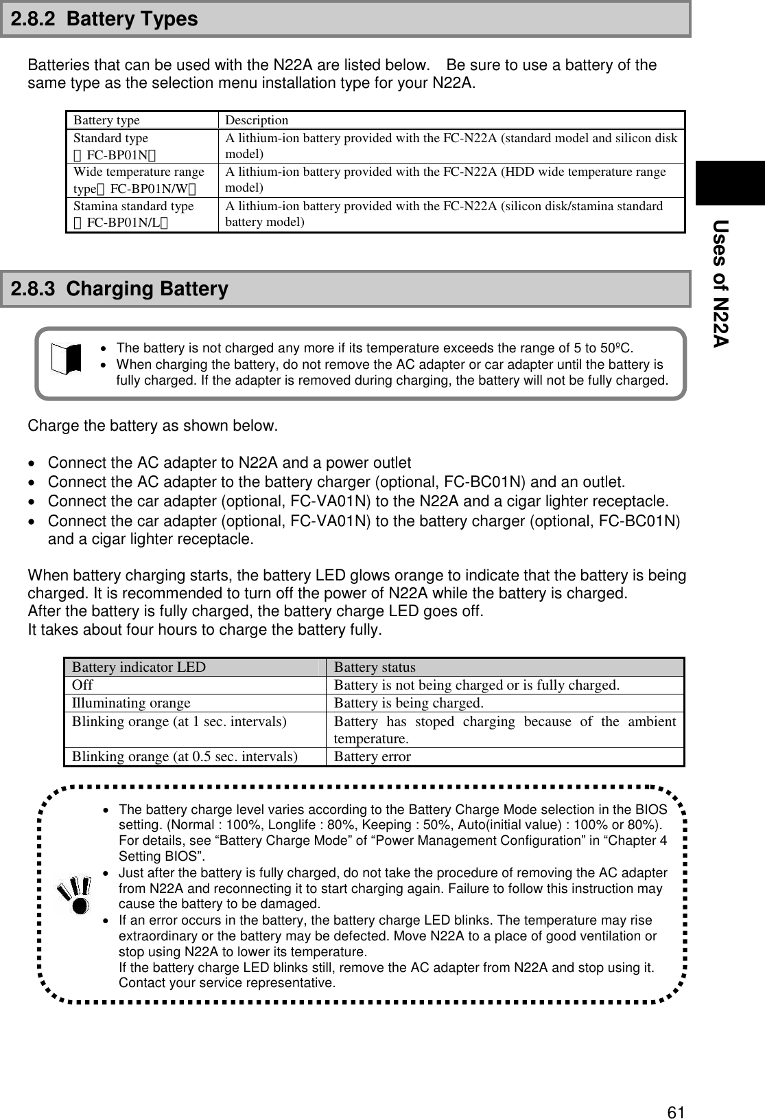
![62 2.8.4 Checking Remaining Battery Level For Windows XP 1. Click [Start] [Control Panel] [Performance and Maintenance] [Power Options]. Then the [Power Options Properties] dialog box appears. 2. Select the [Power Meter] tab and check [Show details for each battery.]. For Windows XP, the dialog box shown below appears to allow you to check the remaining battery level. To activate the screen, wait for several minutes before the AC adapter is disconnected from N22A. “Total time remaining” may be different from the actual operation time depending on the operation status of N22A.](https://usermanual.wiki/NEC/FC-N22A/User-Guide-987184-Page-62.png)

![65 Uses of N22A 2.8.6 Actions Taken for Low Battery Charge Level Decreasing in remaining battery level during battery driving If the battery power remains only a little, the power LED on N22A illuminates in orange or red to inform that the battery should be charged If so, perform either of the following operations depending on situations: Possible supply of AC power through AC outlet Connect the AC adapter to an outlet, or connect the car adapter to a cigar lighter receptacle. Then the battery charge LED illuminates in orange and battery charge is started. When power outlet or car cigarette socket is not available Close applications currently in use, then turn off the power of the N22A. Setting operation of N22A at low battery level The operation and state of N22A in a low or no battery charge level can be defined. 1 Logon to it with a user account having the administrator authority. 2 Click [Start] [Control Panel] [Performance and Maintenance] [Power Options]. 3 Select the [Alarm] tab when the [Power Option Properties] window appears, then set for operation settings. In the lower battery charge level, do not access to a card such as a memory card if used. Accessing to the card may fail because the time taken for the accessing can be longer than the full discharging time. If the battery is discharged fully before data storage, the data is lost.](https://usermanual.wiki/NEC/FC-N22A/User-Guide-987184-Page-65.png)
![66 2.8.7 Initializing Battery Initializing the battery is intended to recover its performance decreased temporarily. The initialization process consists of full charge, full discharge and full recharge of the battery in the order. It takes about 4.5 hours for the initialization. Initialize the battery in the following cases: N22A can be operated by the battery for a shorter period than before. Repeating battery charging in other than the full discharge state may cause the full-chargeable level of the battery to be reduced, which then may shorten the driving period. This is called battery’s memory effect. Because the battery is just purchased or has not been used for a long period, its performance is reduced temporarily. The indicator of the remaining battery level shows some error. 1 Turn off the power of N22A if operated. 2 Install the battery to be initialized. 3 Connect the AC adapter to N22A and the power cord to an AC outlet. (Connect to a cigar lighter receptacle when using a car adapter.) If the battery charge lamp blinks, remove the battery pack from N22A once and install it again. 4 Charge the battery fully. When the battery is fully charged, the battery LED goes off. 5 Turn on the power of N22A. If the NEC logo screen appears, press F2 to display the BIOS Setup Menu. 6 Unplug the power cord from the AC outlet and remove the AC adapter from N22A. (When a car adapter is used, remove the plug from a cigar lighter receptacle and then remove the car adapter from the N22A.) 7 Select [Battery refresh] in the Power Management menu and press Enter. 8 If message “Refresh your battery now?” select [Yes] and press Enter. The following dialog box appears. Refresh battery program Press Y to start refresh, N to exit <ESC> to shutdown system 9 Press Y to start battery initialization. 10 Leave N22A until the power is fully discharged. The power of N22A is automatically turned off. 11 Connect the AC adapter or car adapter to N22A to charge the battery fully. While the battery is initialized, leave the LCD display panel opened. To suspend battery initialization, press Ctrl + Alt + Del to reboot N22A or press the power switch to turn off the power of N22A.](https://usermanual.wiki/NEC/FC-N22A/User-Guide-987184-Page-66.png)
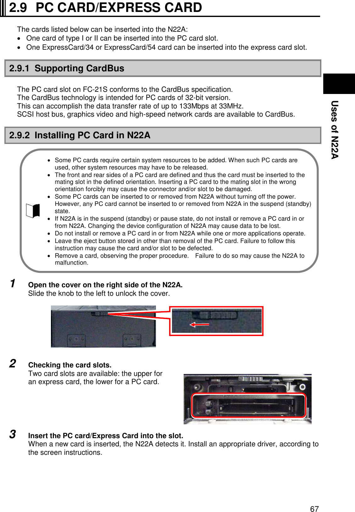
![68 2.9.3 Removing PC Card from N22A Some PC cards may cause icon [Removing or Taking Out Hardware] to appear on the task tray at the lower right corner of the screen at the connection. 1 Double-click the icon to display the [Safely Remove Hardware] or [Remove Hardware] dialog box. 2 Select a device to be removed in the dialog box and click [Stop]. 3 “Stop a Hardware device” is indicated. Select the device to be removed and click [OK]. 4 Click [Close] to close the [Safely Remove Hardware] or [Remove Hardware] dialog box. 5 When the eject button is pushed, the card will pop out a little then pull the card out entirely from the PC card slot.](https://usermanual.wiki/NEC/FC-N22A/User-Guide-987184-Page-68.png)
![70 2.10.2 Protecting Data Set the write protect switch on the SD card to the “LOCK” position. Move the switch to the “LOCK” position for new recording (checkout), editing or file storage. NEC recommends you to back up important data to other media. NEC assumes any responsibility for direct and indirect faults including loss of data saved by customers. NEC recommends that, if an SD card is disposed, it is destroyed physically by using such a tool as a hammer to prevent personal data from being flown out. 2.10.3 Installing or Removing SD Card in/from SD Card Slot Inserting SD Card into SD Card Slot 1 Open the cover on the right side of the N22A. Slide the knob to the left to unlock the cover. 2 Insert a card from the side with cut corner, facing up the label surface. Removing SD Card from SD Card Slot 1 Halt the SD card. 1. Double-click the [Safely Remove Hardware] icon on the task tray at the lower right corner of the screen 2. In the [Safely Remove Hardware] window, click the name of the device to be removed and then click [Stop]. 3. When [Stop of Hardware Device] is displayed, click [OK]. 4. Click [Close] to close the [Safely Remove Hardware] window. The procedure is not required if the SD card is removed in the power-off state. 2 Pushing the SD card allows it to be popped up a little. Then pull out the card. Before the SD card can be stored, it should be saved in a case. When an SD card is inserted to the SD card slot, note the orientation of the card. Inserting an SD card in invalid orientation may cause a fault to occur. Do not insert/remove a card until the Windows login screen or desktop is displayed. Wait for about 30 seconds after resuming from the suspend (standby) or hibernate status before accessing the card. Before the SD card can be removed, the card must always be halted. Do not remove the SD card from the SD card slot in any of the following cases. Failure to follow this instruction may cause important data to be damaged or the SD card to be accessed improperly at the next installation. N22A is in the suspend (standby) or pause state, The SD card opens one or more files (first close the files before removing the SD card), The SD card reads of writes data from or to N22A, or Just after the SD card performs operation such as writing The SD card may access to N22A intermittently.](https://usermanual.wiki/NEC/FC-N22A/User-Guide-987184-Page-70.png)
![72 2.12 COMMUNICATION FEATURE 2.12.1 USB (USB 2.0) USB is the prefix indicating the Universal Serial Bus. The USB has the defined shapes of connectors and allows a computer to connect with up to 127 devices. In addition, the USB provides the plug & play feature to allow the connector of a device to be connected/disconnected without the power of N22A turned off. Available USB devices mainly include pointing device, printers, digital cameras, mobile phones and PHSs. Connecting USB devices to N22A N22A has three USB ports intended to connect with USB2.0 devices on the left side. To connect a USB device to N22A, insert the plug of the USB cable to a USB connector on N22A. Removing USB devices from N22A Some USB devices may cause the icon for removing or taking out hardware to appear on the task tray at the lower right corner of the screen after the connection. 1 Double-click the icon to display the [Safely Remove Hardware] or [Remove Hardware] dialog box. 2 Select a device to be removed in the dialog box and click [Stop]. 3 “Stop a Hardware device” is indicated. Select the device to be removed and click [OK]. 4 Click [Close] to close the [Safely Remove Hardware] or [Remove Hardware] dialog box. Connect/disconnect-proof enhanced connector USB connector (1) is the connect/disconnect-proof enhanced connector enduring 10,000 combinations of connections and disconnections. Some USB devices require driver installations and/or switch settings before or after they are connected to N22A. Refer to the User's Guides of USB devices to be connected to N22A before using them. Some USB devices cannot be directly connected to the N22A due to its shape. In such a case, use a commercially available cable. After disconnecting a USB device from N22A, wait for three seconds or longer before the device is connected again. If the connector of a USB device is connected to a USB connector on N22A quickly or obliquely, N22A may not be able to read signals properly to recognize it as an unknown device. If so, remove the connector from the USB connector once and reconnect it again. When a USB device is connected to N22A, note the orientation of the plug to be inserted to a USB connector. Unless a USB device is removed appropriately, N22A may operate improperly. Remove a USB device in the correct procedure. Do not connect or remove a USB device to/from N22A in the suspend (standby) state, transition to the suspend (standby) state, recovery from the suspend (standby) state, the pause state, transition to the pause state, or recovery from the pause state. If N22A connects with one or more USB devices, it may not be able to enter into the suspend (standby) state. Before N22A can be entered into the suspend (standby) state, the USB devices must be removed. Some OSs may limit the features of USB devices.](https://usermanual.wiki/NEC/FC-N22A/User-Guide-987184-Page-72.png)
![74 2.12.3 LAN The built-in 1000BASE-T LAN module allows N22A to connect with network. The module supports the data transfer rate of up to 1000Mbps. Connecting N22A to network 1 Insert one end of a LAN cable to the RJ-45 connector (LAN connector) on N22A to the depth securely. 2 Insert the other end of the LAN cable to the network connector to the depth securely. Setting LAN 1 Click [Start] [Control Panel] [Network and Internet Connection] [Network Connections]. 2 Double-click [Local Area Connection] to display the [Local Area Connection Status] dialog box. Click [Properties]. 3 The [Local Area Connection Properties] dialog box appears. Provide settings appropriate for the connected network. While N22A operates, do not remove the LAN cable from the hub. If removed, the network connection will be cut out. If the LAN cable is removed during network connection, immediate re-connection may be able to recover the operation. If not, restart OS. During network communication through LAN, connect the AC adapter to N22A. Only the battery can operate N22A for a rather short period. The suspend (standby) or pause state disables the network feature. During network communication, do not enter N22A into the suspend (standby) or pause state. To run an application using network, enter N22A into the suspend (standby) or pause state after asking a system administrator to confirm that the application may be used in suspend (standby) or pause state. Some applications may cause data to be lost when N22A is recovered from the suspend (standby) or pause state. To connect N22A to network, a LAN cable sold separately is required. For gigabit communications, a cable supporting category 6 or 5e is required. If you do not know necessary components, contact a system or network administrator.](https://usermanual.wiki/NEC/FC-N22A/User-Guide-987184-Page-74.png)
![75 Uses of N22A Power-on using LAN controller When the network server is accessed via an internal LAN, the N22A automatically resumes from the suspend (standby) or hibernate status. When it is off, it is automatically turned on. To use the power-on using LAN controller by the LAN built in N22A, the following settings are required. Settings associated with BIOS Setup Menu (common to OSs) 1. Press F2 on the logon screen. The setup menu is displayed. 2. Select [Power management] from the menu bar and then press Enter. Select “Power-on using LAN controller”“Enabled”, and then press Enter. 3. Select [Security] from the menu bar, and then select [Network boot setting] [Keyboard/Mouse Lock] [Disabled], and then press Enter. 4. Press F10 and then select “Yes”. * Without the setting, keyboard and mouse operations are disabled at remote power-on. Settings associated with network adaptor Perform each setting ([Details] and [Power management]) from [Control Panel] [Network and Internet Connection] [Network Connections] right-click on [Local Area Connection] [Properties] [Configuration]. Used OS Setting by OS [Advanced] Wake from system shutdown [Enable] (setting at shipment) Wake On Lan Triggers [Automatic] (setting at shipment) Windows XP [Power Management] Check [Allow this device to bring the computer out of standby.].](https://usermanual.wiki/NEC/FC-N22A/User-Guide-987184-Page-75.png)
![76 2.12.4 Wireless LAN (applied to N22A of wireless LAN installation model only) N22A of wireless LAN installation model allows the wireless LAN feature to be used. N22A of no wireless LAN installation model cannot be equipped with the wireless LAN feature later. Notes on security in use of wireless LAN products The wireless LAN is advantageous to allow LAN connection freely within the radio wave range because data is transmitted among wireless access points including computers through radio waves instead of using LAN cables. On the other hand, since radio waves reach any locations over obstacles (including walls) within a certain range, the following problems may occur without security. Stealing communication data Malicious outsiders may intentionally intercept radio waves to steal communication data as follows: − Personal information including IDs, passwords and credit card numbers − Mail contents Invading into network illegally Malicious outsiders may access to personal and corporate networks without notice to take the following actions: − Acquiring private and confidential information (information leak) − Make communication as a specific person to spread illegal information (spoofing) − Rewrites intercepted communication data to be transmitted (falsification) − Spread computer virus to destroy data and/or systems (destruction) The N22A provides security settings against the problems mentioned above, for wireless LAN cards or wireless access points. In nature, wireless LAN cards and wireless access points have proper security features to cope with these problems. Accordingly, wireless LAN products can be used with their security features to reduce occurrences of the problems. The communication speed and distance vary depending on wireless LAN devices and ambient conditions including radio wave environment, obstacles and installation environment. Due to the property of radio wave, the communication speed is apt to be slower as the communication distance is longer. To allow you to use wireless LAN more comfortable, it is recommended to use wireless LAN devices within a distance as short as possible. To connect N22A to network, wireless LAN access points sold separately and some other devices are required. Using N22A in a country other than Japan may conflict relevant laws in the country. Accordingly, disable the wireless LAN feature of N22A in other than Japan. During network communication, do not enter N22A into the pause or suspend (standby) state. During network communication, connect the AC adapter to N22A. Only the battery can operate N22A for a rather short period. For influences on airplanes or medical devices, see “Cautions on using wireless features” in “For safety”. Confirm that [Wireless LAN Controller] is set [Enabled] in BIOS Setting when using wireless LAN. See “PCI Configuration Submenu” in “Chapter4 SETTING BIOS” in detail. Security settings are not be performed when the N22A is purchased.](https://usermanual.wiki/NEC/FC-N22A/User-Guide-987184-Page-76.png)
![77 Uses of N22A Security enabled by N22A The wireless LAN installed in N22A has the following security features. 1. Preventing interception Setting an encryption key by using the encryption feature allows wireless LAN data among communication devices using the specific encryption key to be encrypted. However, encryption keys may possibly be known by outsiders or decrypted by decryption technology. Accordingly, it is recommended to change encryption keys periodically. For encryption feature settings, see “Setting encryption feature” of “Wireless LAN” in this section. 2. Preventing illegal accesses by setting SSIDs (network names) Setting specific SSIDs (network names) for both access points and communication devices can avoid connections from communication devices without the same SSIDs. However, SSIDs can be known by using devices which have the feature of detecting SSIDs automatically. To avoid this, SSID hiding must be set on access points not to notify them. Registering MAC addresses of connected devices in each access point disables devices not registered to connect to the access point (MAC address filtering). For setting SSIDs, see “Setting encryption feature” of “Wireless LAN” in this section. Installing the wireless LAN driver Install the wireless LAN driver according to the following procedure. 1 Start Windows. 2 Click [Start] [Run…]. 3 Click the [Browse] button to select Wireless_TIC_125458_v10.5.1.0_XP32.exe in the C:¥WINXP¥Drv¥WirelessLAN folder, and then click the [OK] button. 4 The “Important Information” screen is displayed. Check the contents and then click the [Next] button. 5 The “License Agreement” screen is displayed. Check the contents, select “I accept the terms in the License agreement”, and then click the [Next] button. 6 The “Location to Save Files” screen is displayed. Check the installation destination folder and then click the [Next] button. Wait until the file is expanded. 7 The Intel PROSet/Wireless installer screen is displayed. Click the [Install software] button. 8 The Intel software license agreement screen is displayed. Select “I accept the terms in the license agreement”, and then click the [Next] button. 9 The setup type selection screen is displayed. Select “Custom” and then click the [Next] button. To provide the following security, used access points should be applicable to the settings. These settings are only intended to reduce security risks as much as possible but do not assure complete safety to avoid security risks. With Standard setup, some features are not installed such as that disabling wireless LAN connection before logging on to Windows, etc.](https://usermanual.wiki/NEC/FC-N22A/User-Guide-987184-Page-77.png)
![78 10 The features selection screen is displayed. Select the necessary features. To install all sub-features, select “Install this feature and all its sub features” and then click the [Install] button. 11 When the “Installation completed” screen is displayed, click the [OK] button. 12 When the “Restart” screen is displayed, click the [Yes] button. 13 The N22A is restarted. Installation of the wireless LAN driver is completed. On/off of wireless communication 1 Open the cover on the right side of the N22A. Slide the knob to the left to unlock the cover. 2 Slide the wireless communication switch to the right to turn on/off the wireless communication device. The wireless communication lamp will glow blue, indicating that the function can be used. Sliding the switch to the left will turn the wireless communication function off. Setting wireless LAN Perform the following operations. For Windows XP: 1 Click [Start] [All Programs] [Intel PROSet Wireless]. 2 Press Fn + F2 to enable the wireless feature. If you use wireless LAN for the first time, click [Enable Intel PROSet/Wireless]. 3 Connectable wireless networks appears. Select a desired network and click [Connect]. Provide settings appropriate for the selected network. 4 From the menu bar, select [Tool] [Control tools]. 5 The “Create password” screen is displayed. Enter the password and then click the [OK] button. 6 The “Open administrator package” screen is displayed. Click [Create new package] and then click the [OK] button. 7 Click the [Profile] button. 8 The “Management tool – new package” screen is displayed. Click the [Add] button. 9 The “Create wireless profile” screen is displayed. Set the information to connect to the wireless LAN network. 10 When profile setting has completed, click [Close]. Profile name Enter any profile name (name of a file to which the set parameter information is stored). Wireless network name (SSID) Enter the currently used wireless network name. * If you don't know the wireless network name (SSID), ask your network administrator. Management profile types To enable wireless LAN connection before logging on to Windows, select “Before logon/common: Active during the user is logged in. This profile is shared by all users.”](https://usermanual.wiki/NEC/FC-N22A/User-Guide-987184-Page-78.png)
![79 Uses of N22A 11 When “The current package has been changed. Save the changes?” screen is displayed, click [Yes]. 12 The “Save as” screen is displayed. Specify the save destination and file name, and then click [Save]. 13 The “Converting administrator profile to XML” screen is displayed. Click [Browse] to specify the destination, and then click [Close]. 14 When saving completes, click [Finish]. 15 The “Package has been saved” screen is displayed. Click “Apply this package to this computer” and then click the [OK] button. 16 The created profile name is displayed in the “ Intel PROSet Wireless” screen. Click the profile and then click the [Connect] button. 17 Check if the created profile is connected. (“Connected” is displayed on the right of the profile name.) Carefully manage the password. If the connection for the created profile fails, consult your network administrator.](https://usermanual.wiki/NEC/FC-N22A/User-Guide-987184-Page-79.png)
![80 Setting SSID feature Perform the following operations. For Windows XP: 1. Select a connectable wireless network in the [Intel® PROSet/Wireless] dialog box and click [Connect]. 2. Enter proper names in fields [Profile Name] and [Wireless Network Name (SSID)]. 3. Click [Next]. The [Security Settings] dialog box appears. Go to “Setting WEP feature”.](https://usermanual.wiki/NEC/FC-N22A/User-Guide-987184-Page-80.png)
![81 Uses of N22A Setting encryption feature Perform the following operations. For Windows XP: 1. In the [Security Settings] dialog box, set the settings appropriate for the connected wireless network. Then set the settings follow the directions shown on the display screen.](https://usermanual.wiki/NEC/FC-N22A/User-Guide-987184-Page-81.png)
![82 2.12.5 Bluetooth Feature (only for models with this feature installed) This feature allows access to other Bluetooth devices via wireless connection. On/off of Bluetooth Slide the wireless communication switch to turn on Bluetooth feature. (See “On/off of wireless communication” described previously in this chapter.) Checking Bluetooth communication status Put the cursor on the wireless switching icon in the task tray at lower right of the screen. 2.12.6 Serial Port N22A has a serial port connecting with a serial device including a serial mouse or modem. To connect a serial device to N22A, follow the procedure below: 1 From the BIOS setup menu, select [Details] [Peripheral devices], and then press the [Enter] key. 2 Select [Peripheral device submenu] to check that serial port A is enabled. (For details, see “Chapter 4 Setting BIOS”.) 3 Exit the BIOS setup menu, and then turn off the N22A. 4 Insert the cable of a serial device to the serial port on N22A. 5 Turn on the power of N22A. N22A cannot connect with a portable modem getting power through the serial port. Use the built-in battery or a modem using external AC power. Some OSs may limit serial features. The communication speed or distance may vary depending on the target Bluetooth device or peripheral conditions, including radio wave environment, barriers, and installation environment. The communication speed is reduced near a microwave oven being used. To use the Bluetooth feature, set the Bluetooth controller to Enabled (factory default) shown in the Details menu in “Chapter 4 Setting BIOS”. During communication, do not enter the hibernate or suspend (standby) status. During communication, be sure to connect an AC adapter or car adapter to the N22A. Using it with a battery only results in shorter operating time. For influences on airplanes or medical devices, see “Cautions on using wireless features” in “For safety”.](https://usermanual.wiki/NEC/FC-N22A/User-Guide-987184-Page-82.png)

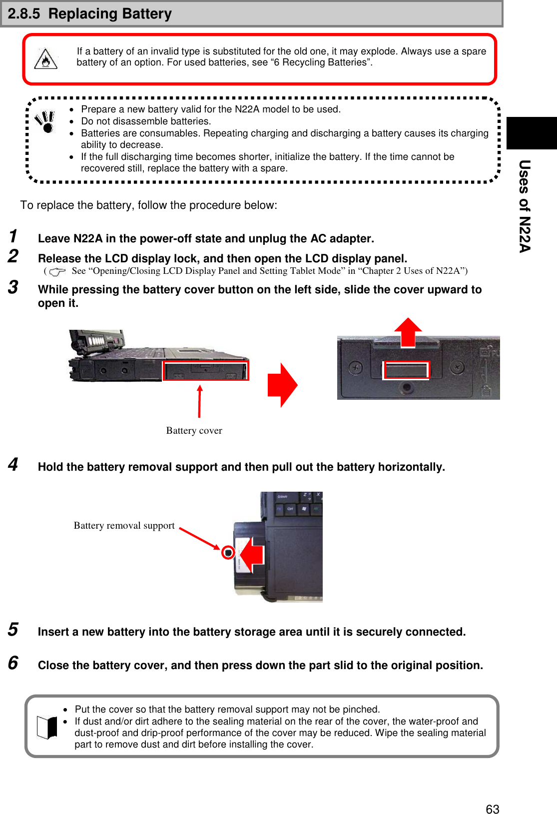
![84 2.13.1 Installing/Removing HDD/Silicon Disks Removal 1 Turn off the power of N22A if operated. 2 Unplug the power cord from the AC outlet and remove the AC adapter from N22A. When using a car adapter, unplug it from the cigar lighter receptacle and then remove the car adapter from the N22A. 3 Remove the battery pack from N22A. See “Replacing Battery” in “Chapter 2 Uses of N22A”for the removal products. 4 Remove the anti-theft screws if they are to be used. 5 While pressing the button of the HDD/silicon disk cover on the right side, slide the cover upward to open it. 6 Hold the HDD removal support and then pull out the HDD horizontally. Installation 1 Insert a hard disk/silicon disk assembly into the disk storage area until it is securely connected. 2 Close the cover, and then press down the part slid to the original position. 3 Attach the anti-theft screws if they are to be used. 4 Install a battery and connect an AC adapter or car adapter. HDDs are extremely precise equipment. Note the following if used. During data read/write (with the access lamp being ON), only a small shock may cause the HDD to be defected. If the HDD is defected, important data may be unavailable at a time and unable to be restored. It is recommended to frequently back up important data for which the same data cannot be created twice. Depending on models of HDDs, a region with no drive number assigned appears in the [Disk Management] dialog box. This is the re-setup region required for re-setup. Do not provide the region with such processing as deletion from targets of disk management. Put the cover so that the HDD removal support may not be caught. The HDD/silicon disk cannot be inserted in the wrong direction (upside down). Carefully check its direction.](https://usermanual.wiki/NEC/FC-N22A/User-Guide-987184-Page-84.png)
![86 3.2 LOGIN PASSWORD The login password is intended to limit users of OS. If a login password is set, the password must be entered to login to the OS. <Setting Procedure> 1. Click [Start] [Control Panel]. 2. Click [User Accounts] to open the dialog box. 3. Click [Change an account] and click the name of the user for which a login password is to be created. 4. Click [Create a password] to open the password setting screen. 5. Enter a password in the [Type a new password:] and [Type the new password again to confirm:] boxes and click [Create password]. 3.3 SECURITY CHIP Setting the security chip allows electronic mails and files to be encrypted and prohibited from being opened without an authentication password. In addition, N22A is equipped with a security chip called TPM (Trusted Platform Module) in its major part to store encryption keys in the security chip. Thus, if only the HDD is withdrawn, the data in the HDD will not be read. A login password can be created only by a user having any of accounts in the local computer including guest and administrator accounts and those created for the computer. To create a tip for a password, anyone using computers can see the tips on the [Welcome] screen. A user having the administrator account of a computer can create or change passwords for all users of the computer. A user having a limited account can only create or change his or her own password or create a tip of the password. If a user having the administrator account of a computer changes a password of a user, then the user loses all the passwords stored for EFS encrypted files, personal certificate, and web site or network resources. To use the security chip, set supervisor and user passwords to restrict accessing to the BIOS SETUP Utility. See “Infineon Security Platform” in “Chapter 5 . Installing OS and Applications ” for details.](https://usermanual.wiki/NEC/FC-N22A/User-Guide-987184-Page-86.png)
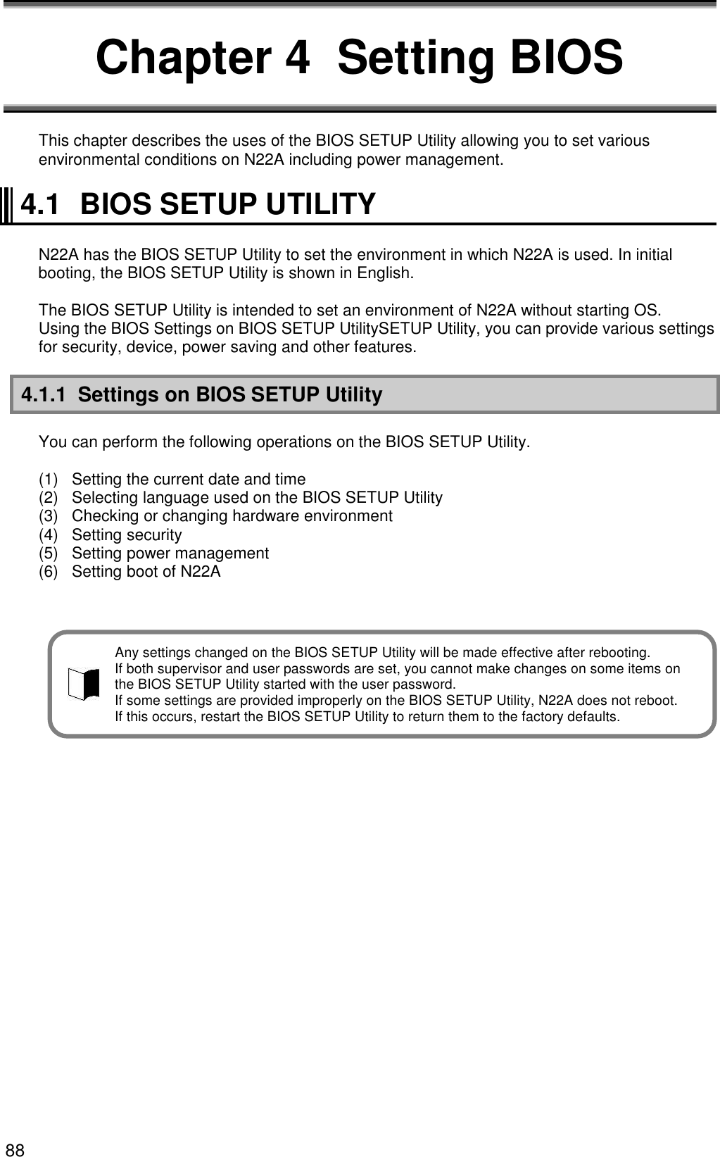
![89 Setting BIOS 4.1.2 Running/exiting BIOS SETUP Utility (1) Starting If the following message appears on the BIOS start screen appearing after the power of N22A is turned on, press F2. The dialog box shown below appears. (2) Exiting 1. Press F10. 2. The [Setup Confirmation] dialog box appears. 3. Select [Yes] and press Enter. The setting values are saved and the BIOS SETUP Utility is exited. Selecting [Exit] on the menu bar can exit the BIOS SETUP Utility. (3) Exit menu On the Exit Menu, you can exit the BIOS SETUP Utility or read or save system settings. Option Description Exit Saving Changes Saves the setting data resulting from changes and exit the BIOS SETUP Utility. (Pressing F10 can do the same exit operation.) Exit Discarding Changes Exits the BIOS SETUP Utility without saving the setting values (discarding the current setting values). Load Setup Defaults Overwrites default values to all setting values. The default values may be different from factory defaults. (See the factory defaults.) Discard Changes Returns the setting values to those before changes. (The BIOS SETUP Utility remains appearing.) Save Changes Saves the setting values resulting from changes. (The BIOS SETUP Utility remains appearing.) Press <F2> to SETUP or Press <F12> to Network boot. or Press <F2> to Enter BIOS SETUP, <F12> to Boot on Network. The factory default of the language is [English (US)]. Menu bar Parameter Key status bar](https://usermanual.wiki/NEC/FC-N22A/User-Guide-987184-Page-89.png)
![90 4.1.3 Loading the BIOS SETUP Defaults The following describes the way to return the data on the BIOS SETUP Utility to their factory defaults. 1. Turn on the power of N22A. 2. If message “Press <F2> to SETUP or Press <F12> to Network boot.” or “Press <F2> to Enter BIOS SETUP, <F12> to Boot on Network.” appears on the BIOS Start screen, press F2. 3. The BIOS SETUP Utility appears. 4. Press F9. The [Setup Confirmation] dialog box appears. 5. Select [Yes] and press Enter. The system reads factory defaults. 6. Press F10. 7. Select [Yes] and press Enter. The system saves the setting values and exits the BIOS SETUP Utility. Now the job is completed. The default values may differ from the factory setting values.](https://usermanual.wiki/NEC/FC-N22A/User-Guide-987184-Page-90.png)

![93 Setting BIOS Setting Item Factory Default Setting Item View Only Tablet Button Tablet Button 1 0h Tablet Button 2 0h Tablet Button 3 0h Tablet Button 4 0h Tablet Button 5 0h [Tb] + Tablet Button 1 0h [Tb] + Tablet Button 2 0h [Tb] + Tablet Button 3 0h [Tb] + Tablet Button 4 0h [Tb] + Tablet Button 5 0h DMI Event Logging Event Log Capacity ――― Event Log Validity ――― View DMI Event Log ――― Clear All DMI Event Logs No Event Logging Enabled Mark DMI Events As Read ――― *1: Models with a wide temperature range HDD and silicon disk installed are “Not Used.” (3) Security Setting Item Factory Default Setting Item View Only Supervisor Password is ――― User Password is ――― Set Supervisor Password (No value) Set User Password (No value) User Password Protection Disabled Password on boot Disabled Network Boot Setting Keyboard/Mouse Lock Enabled BIOS LOCK *2 Disabled HardDisk Security Fixed disk boot sector Normal Assign HDD Password (No value) Secondary Master HDD Password Disabled Hard Disk Erase ――― No-Execute Memory Protection Enabled Security Chip Configuration TPM support Enabled Current TPM State *3 ――― Change TPM State *3 No Change Password Authentication *3 Disabled *2: This option appears when the supervisor password is set and [Password on boot] is set to [Enabled]. *3: Not displayed when TPM support is set to “Disabled”.](https://usermanual.wiki/NEC/FC-N22A/User-Guide-987184-Page-93.png)
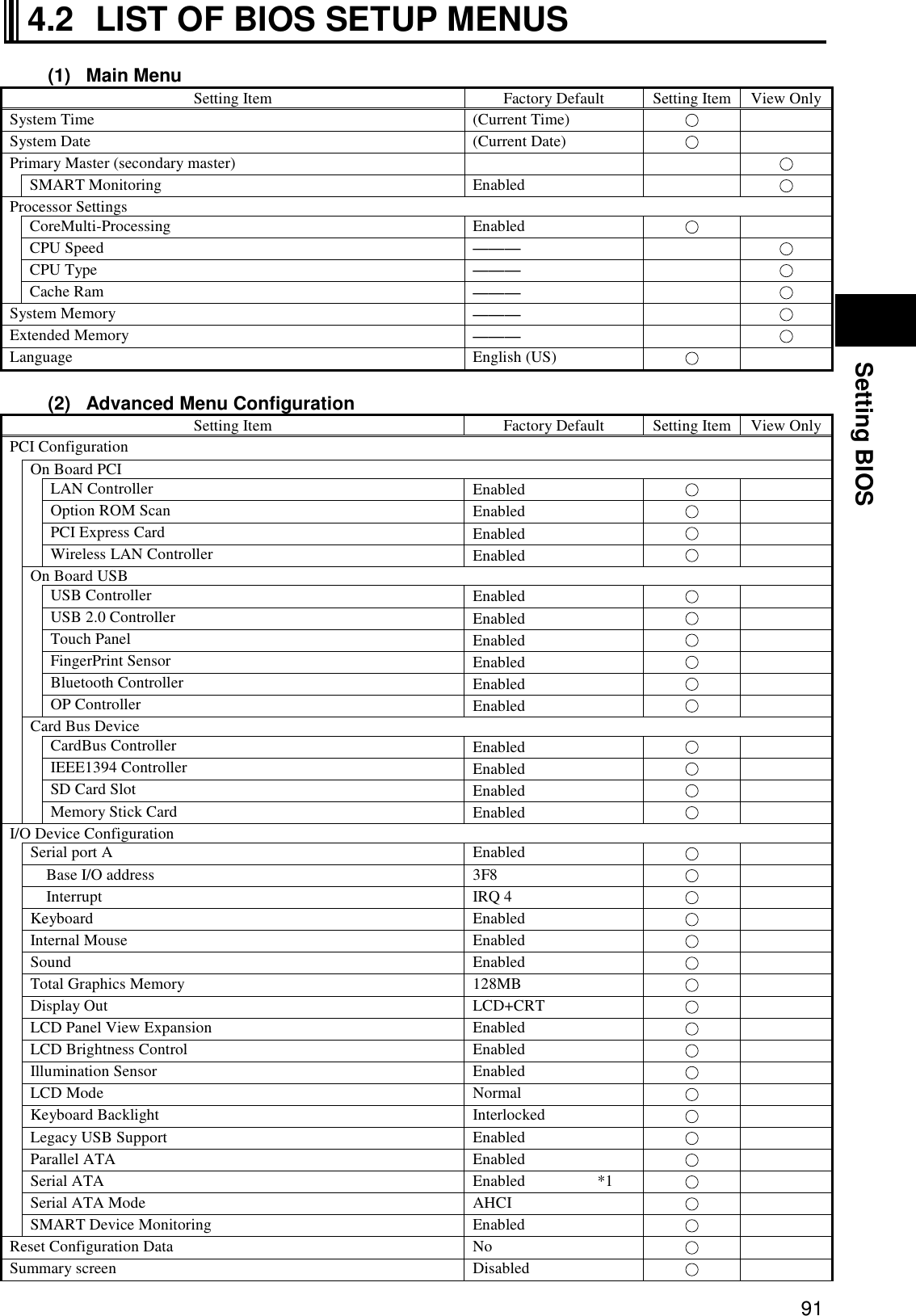
![95 Setting BIOS 4.3 MAIN MENU (1) System Time Enter the current time in format “hh:mm:ss” (hh: hour, mm: minute and ss: second) (2) System Date Enter the current date in format “yyyy/mm/dd” (yyyy: year, mm: month and dd: date) (3) Primary Master (Secondary Master) Indicates the information on devices connected to the primary master (including capacities and types). If you move the cursor to this option and press Enter, the relevant setting submenu appears on the screen. Select [Advanced] [I/O Device Configuration] [SMART Device Monitoring] to display the setting information. If you change some settings, the new information resulting from the change is displayed after rebooting. Option Parameter Description SMART Monitoring (View only) [Enabled] or [Disabled] appears if the [SMART Monitoring] is enabled or disabled, respectively. This setting cannot be changed. (4) Processor Settings Indicates the processor information. If you move the cursor to this option and press Enter, the relevant setting submenu appears on the screen. Option Parameter Description Displayed value Multi-core mode Disabled Enabled When set to [Disabled], the CPU operates in the single core mode. When set to [Enabled], the CPU operates in the multiple core mode. CPU Speed (View only) Indicates the speed of the installed CPU (by the number of clocks) 1200MHz CPU Type (View only) Indicates the type of the installed CPU. Genuine Intel(R) CPU Cache Ram (View only) Indicates the capacity of the second cache of the installed CPU. 2048KB * 1 * Shaded value: Factory-set *1 Installation of 256MB memory (5) System Memory Indicates the capacity of the system memory. (6) Extended Memory Indicates the capacity of the extended memory. (7) Language Specify the language used in BIOS. You can select either Japanese or English. A standard hard disk (80 GB) is displayed as “Primary master”. A wide temperature range-capable hard disk (40 GB) or silicon disk (20 GB) is displayed as “Secondary master”. The factory default of the language is [English (US)].](https://usermanual.wiki/NEC/FC-N22A/User-Guide-987184-Page-95.png)
![96 4.4 ADVANCED MENU CONFIGURATION 4.4.1 Advanced Menu Configuration (1) PCI Configuration This option allows you to provide settings for PCI devices built in N22A. If you move the cursor to this option and press Enter, the relevant setting submenu appears on the screen. For the submenu, See “PCI Configuration Submenu” in “Chapter 4 Setting BIOS.” (2) I/O Device Configuration This option allows you to provide settings for peripherals built in N22A. If you move the cursor to this option and press Enter, the relevant setting submenu appears on the screen. For the submenu, See “PCI Configuration Submenu” in “Chapter 4 Setting BIOS.” (3) Setting value initialization This option allows you to initialize the system setting values. Option Parameter Description Setting value initialization No Yes Set to [Yes] to initialize the resource information. *Shaded value: Factory-set (4) Summary screen The option allows you to specify whether the system setting status is displayed on booting. Option Parameter Description Summary screen Disabled Enabled Set to [Enabled] to display the system setting status on booting. *Shaded value: Factory-set (5) Silent Boot This option allows you to select the screen displayed on booting. Option Parameter Description Silent Boot POST screen Logo screen Non screen Set to [POST screen] to display the Power-On Self-Test (POST) screen without displaying the NEC logo. Set to [Logo screen] to display the NEC logo and shorten the booting time. Set to [Non screen] to display neither the POST nor NEC logo screens. (The booting time is not made shorter.) *Shaded value: Factory-set (6) QuickBoot Mode This option allows you to specify whether a part of tests is skipped on booting or not. Option Parameter Description QuickBoot Mode Disabled Enabled Set to [Disabled] to execute all tests. Set to [Enabled] to skip a part of tests. This can shorten the booting time if the extended memory capacity is considerably large. *Shaded value: Factory-set (7) Fn/Left Ctrl key replacement This option allows the features of Fn and Left Ctrl on the keyboard to be replaced with each other. Option Parameter Description Fn/Left Ctrl key replacement Disabled Enabled Set to [Disabled] to operate Fn and Left Ctrl as they are. Set to [Enabled] to replace the features of Fn and Left Ctrl of the keyboard to be replaced each other. *Shaded value: Factory-set](https://usermanual.wiki/NEC/FC-N22A/User-Guide-987184-Page-96.png)
![97 Setting BIOS (8) Tablet Button This option allows you to assign features to the tablet buttons. If you move the cursor to this option and press Enter, the relevant setting submenu appears on the screen. For the submenu, see “4.3.4 Tablet Button Submenu”. (9) DMI Event Logging This option displays the system event log occurring on booting or allows you to set the system event log. If you move the cursor to this option and press Enter, the relevant setting submenu appears on the screen. Option Parameter Description Event Log Capacity (View only) If “Space Available” appears, the area where DMI event log information is stored has empty space. If “Full” appears, the area where DMI event log information is stored has no empty space. Event Log Validity (View only) “Valid” appears normally (normal state). “Invalid” appears if the event log area becomes illegal due to power shutdown during storage of event log. If “Invalid” appears, run [Clear All DMI Event Logs] to recover the normal state. View DMI Event Log (View only) Press Enter to display the contents in the DMI event log entirely. Clear All DMI Event Logs No Yes Select [Yes] to clear the DMI event log entirely after rebooting. Event Logging Disabled Enabled Set to [Disabled] not to record the DMI event log. Set to [Enabled] to record the DMI event log. Mark DMI Events As Read Yes No Press Enter and select [Yes] to make the currently displayed log read already. *Shaded value: Factory-set DMI (Desktop Management Interface) is a standard specification of hardware-to-software interface intended to simplify management of each computer for easy system management.](https://usermanual.wiki/NEC/FC-N22A/User-Guide-987184-Page-97.png)
![98 4.4.2 PCI Configuration Submenu The PCI Configuration Submenu allows you to set features of PCI devices built in N22A. Option Parameter Description On Board LAN Provide settings for on-board LAN devices. If you move the cursor to this option and press Enter, the relevant setting submenu appears on the screen. LAN Controller Disabled Enabled Enable or disable wired LAN controller. Option ROM Scan PCI Express Card Wireless LAN Controller Disabled Enabled Enable or disable wireless LAN controller. On Board USB Provides settings for on-board USB devices. If you move the cursor to this option and press Enter, the relevant setting submenu appears on the screen. USB Controller Disabled Enabled Enable or disable the USB controller. Set to [Disabled] to disable even the USB2.0 controller. USB connectors become unavailable (I/O lock). USB 2.0 Controller Disabled Enabled Enable or disable the USB2.0 controller. Set to [Disabled] to disable the USB2.0 controller. USB devices operate in the USB1.1 specification. Touch Panel GPS Controller FingerPrint Sensor Bluetooth Controller Card Bus Device CardBus Controller IEEE1394 Controller SD Card Slot Memory stick Card *Shaded value: Factory-set 4.4.3 I/O Device Configuration Submenu The I/O Device Configuration Submenu allows you to set features of peripherals built in N22A. Option Parameter Description Serial port A Disabled Enabled Set to [Disabled] to disable serial port A (I/O lock) and release the interrupt. Set to [Enabled] to enable serial port A. I/O Base Address 3F8 2F8 3E8 2E8 Specify the I/O base address of serial port A. Interrupt IRQ 4 IRQ 3 Specify the IRQ of serial port A. Internal Mouse Disabled Enabled Set to [Disabled] to disable the touch pad. Set to [Enabled] to enable the touch pad. Touch Panel Disabled Enabled Set to [Disabled] to disable the touch panel. Set to [Enabled] to enable the touch panel. Sound / Modem Disabled Enabled Set to [Disabled] to disable sound (makes the audio controller disabled). Set to [Enabled] to enable sound. Total Graphics Memory Specify the graphic memory capacity.](https://usermanual.wiki/NEC/FC-N22A/User-Guide-987184-Page-98.png)
![99 Setting BIOS Option Parameter Description Display Out CRT LCD LCD + CRT Specify the monitor(s) on which screen data is displayed. Set to [CRT] to display screen data on the external monitor in booting. (Screen data is not displayed on the built-in LCD monitor.) Set to [LCD] to display screen data on the built-in LCD monitor in booting. Set to [LCD + CRT] to display screen data on both monitors in booting. LCD Panel View Expansion Enabled Disabled Specify the LCD panel view expansion feature. If this option is set to [Disabled], a part of area is not displayed at the top and bottom sides and the left and right sides on a display screen smaller than the maximum display size of the LCD panel. (However, parameter [Disabled] is unavailable if the screen resolution is set to the maximum value in OS setting.) If this option is set to [Enabled], display image smaller than the maximum display size of the LCD panel is expanded to be displayed on the full screen. LCD Brightness Control Disabled Enabled Specify the LCD brightness control method. Set to [Disabled] to have the LCD brightness controlled by OS or driver. (Tablet buttons 4 and 5 and hot keys Fn + F7, Fn + F8 are disabled to change the LCD brightness.) Set to [Enabled] to have the LCD brightness controlled by BIOS. (Tablet buttons 4 and 5 and hot keys Fn + F7, Fn + F8 are enabled to change the LCD brightness.) Keyboard Backlight Connect Disconnect Specify the keyboard backlight brightness control method. Set to [Interlocked] to interlock with the LCD brightness. The keyboard backlight brightness is increased/decreased by pressing Fn + F7/Fn + F8. Keyboard backlight is turned on/off by pressing Fn + F1. Set to [Independent] to adjust the keyboard backlight brightness in 8 levels (dark to bright) or turn on/off it by pressing Fn + F1. Legacy USB Support Disabled Enabled Enable or disable the legacy USB feature. Set to [Disabled] to disable the legacy USB feature. Booting from an external USB device is also disabled. Set to [Enabled] to enable the legacy USB feature. Parallel ATA Disabled Enabled Set to [Disabled] to disable the built-in parallel ATA IDE adapter. Set to [Enabled] to enable the built-in parallel ATA IDE adapter. Serial ATA Disabled Enabled Set to [Disabled] to disable the built-in serial ATA IDE adapter. Set to [Enabled] to enable the built-in serial ATA IDE adapter. * For the Linux model with a wide temperature range HDD, this item is set to [Disabled] at factory. Serial ATA Mode Disabled Enabled Enable or disable the AHCI feature. Set to [Disabled] to disable the AHCI feature. Set to [Enabled] to enable the AHCI feature. SMART Device Monitoring Disabled Enabled Set to [Disabled] not to provide S.M.A.R.T. monitoring for IDE devices. Set to [Enabled] to provide S.M.A.R.T. monitoring for IDE devices. * Only for models featuring the function *Shaded value: Factory-set](https://usermanual.wiki/NEC/FC-N22A/User-Guide-987184-Page-99.png)
![101 Setting BIOS 4.4.4 Tablet Button Submenu The Tablet Button Submenu allows you to assign features to tablet buttons. Option Parameter Description Tablet Button 1 Tablet Button 2 Tablet Button 3 Tablet Button 4 Tablet Button 5 [Tb] + Tablet Button 1 [Tb] + Tablet Button 2 [Tb] + Tablet Button 3 [Tb] + Tablet Button 4 [Tb] + Tablet Button 5 00h 00h ~ FFh Assign features to tablet buttons. Enter the key codes to be set. Key codes shown in the table below are only available If [0] is set to an option, the serigraphed standard feature is enabled for the option. If [FFFF] is set to an option, the feature of the option is disabled. *Shaded value: Factory-set The table below shows the correspondence between actual tablet buttons and options. Tb (1) (2) (3) (4) (5) No Option Usual feature Feature of [Tb] + [Tablet button] (1) Tablet Button 1 Ctrl + Alt + Del ESC (2) Tablet Button 2 Screen rotation Tab (3) Tablet Button 3 Enter Starting screen keyboard (4) Tablet Button 4 LCD brightness UP PgUp (5) Tablet Button 5 LCD brightness Down PgDn The tablet buttons can only have the features listed in the table below. Do not specify any values other than those in the table below. Feature Setting value Ctrl+Alt+Del 0100 h Screen rotation * E06D h Enter 005A h LCD brightness UP 0107 h LCD brightness Down 0108 h ESC 0076 h Tab 000D h Starting screen keyboard * E06A h PgUp key 0075 h PgDn key 0072 h Keyboard backlight OFF 0101 h Switching wireless LAN enabled/disabled 0102 h Switching screen output port 0103 h LCD backlight OFF 0104 h FC button 1 * E048 h FC button 2 * E03A h * [Screen rotation], [Starting screen keyboard], [FC button 1] and [FC button 2] are enabled only in operation of Windows [FC Button 1] and [FC Button 2] can run the execution command (or application starts) registered on the [FC Button Setup utility] dialog box.](https://usermanual.wiki/NEC/FC-N22A/User-Guide-987184-Page-101.png)
![102 4.5 SECURITY MENU The N22A can limit the BIOS Setup Menu users by setting a supervisor password and user password, and prevent unauthorized use of the hard disk drive with other than the main unit by setting a hard disk password. 4.5.1 Security (1) Supervisor Password This option indicates whether a supervisor password is set or not. Option Parameter Description Supervisor Password is (View only) “Set” appears when a supervisor password is set. “Clear” appears when a supervisor password is not set. (2) User Password This option indicates whether a user password is set or not. For the option and description on a user password, see “(1) Supervisor Password” above. (3) Set Supervisor Password This option allows you to set a supervisor password. If a supervisor password is set, accessing to the BIOS SETUP Utility is limited. <Supervisor password setting procedure> 1. Select [Set Supervisor Password] and press Enter. The setting dialog box appears. 2. Enter a new password in field [Enter New Supervisor Password] and press Enter. 3. Enter the same password in field [Confirm New Supervisor Password] for confirmation and press Enter. 4. When message “Changes have been saved.” appears, press Enter. The value in field [Supervisor Password is] is changed to [Set]. To change a password already set, enter the current password in field [Enter Current Password] for confirmation, press Enter and then enter a desired password in the same way as setting a new password. A password can only consist of up to eight alphanumeric characters and is not case-sensitive. If you press Enter without entering anything in the new supervisor password field, both the supervisor and user passwords are cancelled. To cancel the user password only, cancel the supervisor password once and then set the supervisor password only. Re-setup of N22A cannot cancel the passwords. Forgetting a password, you cannot cancel the password. Accordingly, if a password is set, manage it carefully.](https://usermanual.wiki/NEC/FC-N22A/User-Guide-987184-Page-102.png)
![103 Setting BIOS (4) Set User Password This option allows you to set a user password. If a user password is set, accessing to the system on booting is limited. <User password setting procedure> 1. Select [Set User Password] and press Enter. The setting screen appears. 2. Enter a new password in field [Enter New Password] and press Enter. 3. Enter the same password in field [Confirm New Password] for confirmation and press Enter. 4. When message “Changes have been saved.” appears, press Enter. The value in field [User Password is] is changed to [Set]. (5) User Password Protection This option indicates whether the user password is protected or not. Option Parameter Description User Password Protection Disabled Enabled Set to [Enabled] not to allow you to change the user password if you enter the setup menu with the user password. * Shaded value: Factory-set (6) Password on boot Option Parameter Description Password Disabled Enabled et to [Disabled] not to request you to enter the user on boot passwords on booting. Set to [Enabled] to request you to enter the user password on booting. * This option becomes selectable after a supervisor password is set. Shaded value: Factory-set Without supervisor password, you cannot select an item to set the user password. First set the supervisor password. Entering the BIOS SETUP Utility with the supervisor password, you can check and change all setting items. However, entering into it with the user password, you cannot change the following items (view only). Items [System Time], [System Date] and [Language] on the [Main] menu Items [Exit Saving Changes], [Exit Discarding Changes] and [Save Changes] on the [Exit] menu Forgetting a password, you cannot cancel the password. Accordingly, if a password is set, manage it carefully.](https://usermanual.wiki/NEC/FC-N22A/User-Guide-987184-Page-103.png)
![104 (7) Network Boot Setting The option allows you to provide settings on network starting. If you move the cursor to this option and press Enter, the relevant setting submenu appears on the screen. Option Parameter Description Keyboard/Mouse Lock Disabled Enabled Allows you to set the operations of the keyboard and mouse on remote (PME) booting (until OS is started). Set to [Disabled] to allow the keyboard and mouse to be used. Set to [Enabled] to lock the keyboard and mouse to be unavailable. BIOS LOCK Disabled Enabled Allows you to set [Password on boot] on remote (PME) booting. Set to [Disabled] to boot without request of entering the user password. Set to [Enabled] to request you to enter the user password. This option appears when the supervisor password is set and [Password on boot] is set to [Enabled]. *Shaded value: Factory-set (8) HardDisk Security This option allows you to set the security of the HDD. If you move the cursor to this option and press Enter, the relevant setting submenu appears on the screen. On the submenu, you can set security features of the HDD as described below. Option Parameter Description Fixed disk boot sector Normal Write Protect Set to [Write Protect] to prohibit data from being written to the boot sector in the HDD to protect the sector from virus. Assign HDD Password (No value) Allows you to set an HDD password. See Supplement 1: Setting HDD password” for how to set an HDD password. Secondary Master HDD Password Enabled Disabled Set to [Enabled] to set the HDD password in the secondary master hard disk drive. Hard Disk Erase (No value) Erases data in the HDD. See “Supplement 2: Erasing HDD data” for how to clear data. *Shaded value: Factory-set Supplement 1: Setting HDD password There are two HDD passwords, or HDD master and HDD user passwords. <HDD password setting procedure> 1. Select [Assign HDD Password] and press Enter. 2. Enter a supervisor password in field [Enter New Master Password.] and press Enter. 3. Enter the same password in field [Confirm New Master Password.] for confirmation and press Enter. 4. The [Assign HDD User Password] dialog box appears. 5. Enter a supervisor password in field [Enter New User Password] and press Enter. 6. Enter the same password in field [Confirm New User Password] for confirmation and press Enter. 7. Select [Primary Master HDD Password] and press F5 or F6 to set the option to [Enabled]. Remote (PME) booting means that the administrator PC remotely boots a client PC. Setting a HDD user password can prohibit the HDD from being used in another PC illegally.](https://usermanual.wiki/NEC/FC-N22A/User-Guide-987184-Page-104.png)
![105 Setting BIOS Supplement 2: Erasing HDD data The following shows the erase HDD data procedure. NSA (Random(1) Random(2) 00h) Writes [random data random data 00] in the order in the entire HDD area. The erase HDD procedure conforms to the method recommended by NSA. <HDD erase procedure> 1. Select [Hard Disk Erase] and press Enter. The [Setup Confirmation] dialog box appears. 2. Select [Yes] to exit the BIOS SETUP Utility and transit to the erase HDD dialog box. The following dialog box appears. 3. Press Y to start erasing the HDD. Press N to cancel the erase HDD procedure and start system booting. Press ESC to shutdown the system (power-off). (9) No-Execute Memory Protection This option allows you to specify whether the DEP (Data Execution Prevention) feature of the HDD is enabled or not. Option Parameter Description No-Execute Memory Protection Enabled Disabled Enable or disable the DEP (Data Execution Protection Prevention) feature. Set to [Enabled] to enable the DEP feature. Set to [Disabled] to disable the DEP feature. *Shaded value: Factory-set DEP (Data Execution Prevention) is a feature of preventing illegal programs and data from being executed in hardware manner. DEP disables computer virus to write or run program codes illegally. If you enter the BIOS SETUP Utility with the user password, item [Hard Disk Erase] does not appear in the menu. To boot N22A (to start Windows installed in the primary master hard disk), the HDD master and HDD user passwords being set may not be entered even if [Primary Master HDD Password] is set to [Enabled]. After the HDD data is erased, the data having been stored in the HDD cannot be restored. Before erasing the HDD, make sure that necessary data does not remain in the HDD. Erasure takes 80 to 140 minutes for a standard HDD (80 GB), 25 to 30 hours for a wide temperature range HDD (80 GB), and 5 to 6 hours for a silicon disk (20 GB).](https://usermanual.wiki/NEC/FC-N22A/User-Guide-987184-Page-105.png)
![106 (10) Security Chip Configuration This option allows you to provide settings for the security chip. If you move the cursor to this option and press Enter, the relevant setting submenu appears on the screen. On the submenu, you can set features of the security chip as described below. Option Parameter Description TPM support Disabled Enabled Enable or disable the security chip called TPM (Trusted Platform Module). Set to [Disabled] to disable the security chip (TPM). Set to [Enabled] to enable the security chip (TPM). Current TPM State (No setting) Shows the setting status of the security chip (TPM). (Not displayed when TPM support is set to [Disabled].) Change TPM State No Change Enable & Activate Deactivate & Disable Clear Enable or disable the security chip (TPM) feature. Set to [No Change] not to change the security chip (TPM) status. Set to [Enable & Activate] to enable the security chip (TPM) feature. Set to [Deactivate & Disable] to disable the security chip (TPM) feature. Set to [Clear] to return the security chip (TPM) to the factory setting. (Not displayed when TPM support is set to [Disabled].) Password Authentication Disabled Enabled Enable or disable password lock when setting the security chip (TPM) feature. Set to [Disabled] so as not to request entering a password when setting the security chip (TPM) feature. Set to [Enabled] to request entering of a password when setting the security chip (TPM) feature. *Shaded value: Factory-set If the security chip is set to Enabled, set supervisor and user passwords to limit accessing to the BIOS SETUP Utility. For details on security chips or setting procedure of the utility, see “Infineon Security Platform” in “Chapter 5 Installing OS and Applications”.](https://usermanual.wiki/NEC/FC-N22A/User-Guide-987184-Page-106.png)
![107 Setting BIOS 4.5.2 I/O Lock Feature The I/O lock disables the I/O feature, measures to interchange data with external devices, on the BIOS SETUP Utility. I/O lock can be enabled by setting the following in the BIOS Setup Menu. (1) How to lock the LAN controller [Advanced] [PCI Setting] [On Board LAN Device] [LAN Controller] [Do not use] (2) How to lock the wireless LAN controller [Advanced] [PCI Setting] [Wireless LAN Device] [Wireless LAN Controller] [Do not use] (3) How to lock the USB controller [Advanced] [PCI Setting] [On Board USB Device] [USB Controller] [Do not use] (4) How to lock serial port A [Advanced] [Peripheral Setting] [Serial Port A] [Do not use] (5) Locking card bus controller (PCMCIA) [Details] [Peripheral device settings] [Card bus controller] [Disabled] (6) Locking bluetooth controller [Details] [Peripheral device settings] [Bluetooth controller] [Disabled] (7) Locking parallel ATA [Details] [Peripheral device settings] [Parallel ATA] [Disabled] (8) Locking serial ATA [Details] [Peripheral device settings] [Serial ATA] [Disabled] 4.5.3 Clearing BIOS Passwords N22A can limit users of the BIOS SETUP Utility by supervisor and user passwords and prevent the HDD from being used illegally by other computers with HDD passwords. (1) Clearing passwords by BIOS SETUP Utility To release passwords, start the BIOS SETUP Utility, enter the existing supervisor password in [Set Supervisor Password] in the Security Menu and press Enter without entry of new password. Forgetting a password, you cannot cancel the password. Accordingly, if a password is set, manage it carefully.](https://usermanual.wiki/NEC/FC-N22A/User-Guide-987184-Page-107.png)
![108 4.6 POWER MANAGEMENT CONFIGURATION 4.6.1 Power Management Configuration This menu allows you to set power management features. Option Parameter Description Power Switch Lock Disabled Enabled Specify whether the power inhibit release switch is enabled or disabled. Set to [Enabled] to enable the power switch with the power inhibit release switch being pressed. (Pressing the power switch only cannot turn on/off the power.) Wake On LAN Disabled Enabled Specify whether the power is turned on by the wake on LAN feature of the internal LAN controller or not. Wake On PC Card Wake On ExppressCard Wake On Ring Disabled Enabled Specify whether the power of the device connected to the serial port is turned on or not. Restore On AC/Power Loss Stay Off Last State Power On Specify the state recovered when the power of the AC adapter is interrupted and then on again. Set to [Stay Off] not to turn on the power at AC power-on of the AC adapter. Set to [Last State] to return to the state at AC power-off of the AC adapter. If AC power of the AC adapter is interrupted with the power being on, the power is turned on. If AC power of the AC adapter is interrupted with the power being off, the power is not turned on. Set to [Power On] to turn on the power at AC power-on of the AC adapter. Restore On AC/Power Loss from S4 Intel SpeedStep(R) technology Disabled Enabled Specify whether the Intel SpeedStep technology is enabled or disabled. Set to [Disabled] to operate N22A in the battery optimization performance. Set to [Enabled] to operate N22A in the performance optimized by the Intel SpeedStep technology. (The CPU frequency varies depending on load to CPU.) C-States Disabled Enabled Specify the CPU power management status. Set to [Disabled] to set the CPU power management to C1 status. Set to [Enabled] to set the CPU power management to C1, C2, C3, and C4. CPU Power Level Minimum Standard Maximum Specify the CPU power level when the CPU is entered into idling state during OS operation. Set to [Minimum] to transit the CPU to the minimum power consumption state. Set to [Standard] to transit the CPU to the normal power consumption state. Set to [Maximum] to transit the CPU to the maximum power consumption state. Power Mode Disabled Enabled Specify the power save mode. Set to [Disabled] to operate the system in the normal mode. Set to [Enabled] to operate the system in the power save mode.](https://usermanual.wiki/NEC/FC-N22A/User-Guide-987184-Page-108.png)
![109 Setting BIOS Option Parameter Description Battery Charge Mode Normal LongLife Keeping Auto Specify the battery charging mode. Set to [Normal] to charge the battery fully. Set to [LongLife] to charge the battery at level of 80%. (Select this if you want to make the battery life longer.) Set to [Keeping] to charge the battery at level of 50%. (Select this if the battery is stored.) Set to [Auto] to select [Normal] in the normal state but [LongLife] if the battery temperature becomes higher. Battery Refresh (No setting) Recovers the battery feature. Select [Yes] and press Enter to refresh the battery. *Shaded value: Factory-set](https://usermanual.wiki/NEC/FC-N22A/User-Guide-987184-Page-109.png)
![110 4.7 SYSTEM MENU The System Menu allows you to set system features as described in the table below. Option Parameter Description System Management Indicates system information. If you move the cursor to this option and press Enter, the relevant setting submenu appears on the screen. System Part # Indicates the product name of N22A. System Serial # Indicates the serial number of N22A (not used now). BIOS Revision Indicates the BIOS revision of N22A. EC FW Revision (View only) Indicates the EC-FW revision of N22A. Temperature Sensor Disabled Enabled Specify the temperature monitoring feature. Set to [Disabled] to disable the temperature monitoring feature at system booting. Set to [Enabled] to enable the temperature monitoring feature at system booting. Upper Limit [°C] 75 Wide Range Temperature Support:80 Indicates the upper limit of the monitoring temperature. Lower Limit [°C] 5 Wide Range Temperature Support:-25 Indicates the lower limit of the monitoring temperature. Voltage Sensor Disabled Enabled Specify the voltage monitoring feature. Set to [Disabled] to disable the voltage monitoring feature at system booting. Set to [Enabled] to enable the voltage monitoring feature at system booting. POST Errors Disabled Enabled Specify the operation when an error is found during POST. Set to [Disabled] to have the system continue booting if an error is found by the POST. Set to [Enabled] to suspend booting if an error is found by the POST and indicate the error content. HDD Thermal Sensor *1 Disabled Enabled Specify the HDD temperature monitoring feature. Set to [Disabled] to disable the HDD temperature monitoring feature at system booting. Set to [Enabled] to enable the HDD temperature monitoring feature at system booting. Illumination sensor Disabled Enabled Set the illuminance sensor. If “Disabled” is selected, the illuminance sensor is disabled. If “enabled” is selected, the illuminance sensor is enabled. LCD Mode Normal Enhanced Change the LCD brightness level. If “Normal” is set, the brightness is changed in the range from the lowest to level 13. If “Enhanced” is set, the brightness is changed in the range from the lowest to level 16. Self-Diagnostic Program *Shaded value: Factory-set *1: For wide temperature range HDD, “HDD Temperature Sensor” is not displayed. Operations when temperature sensor is set to “Use” Monitor system temperature (internal temperature sensor) at power on (BIOS startup), where an error message will appear, after BIOS startup is completed, if the temperature is outside the range between upper and lower limits of the setting values. The temperature sensor has a margin of error. In case of operating at temperatures close to the lower limit of monitoring temperature, adjust the setting value if an error message appears after BIOS startup is completed. Do not change “Upper Limit of Monitoring Temperature” to a greater value since the main unit internal temperature will rise after power is turned on. This operation is performed only on startup, and will not be performed after the operating system starts.](https://usermanual.wiki/NEC/FC-N22A/User-Guide-987184-Page-110.png)
![111 Setting BIOS 4.8 BOOT MENU 4.8.1 Boot Order Configuration This menu lists boot devices in the preference order. The top device first tries to start the OS. If the device cannot start the OS due to such a reason as no existence of OS, the next device tries to start the OS. To change the boot device, press PgUp or PgDn to move the cursor to the device to be used to start the OS. Press F5 or F6 to move the cursor upward or downward in the list, respectively. Press x to move the cursor in [Boot priority order] and [Excluded from boot order]. Up to eight devices can be registered in [Boot priority order]. The factory set priority is defined as follows: 1: USB CD-ROM 2: USB FDC 3: Master HDE 4: Onboard LAN device The actual dialog box appears as follows: Boot priority order 1: USB CDROM: --------------------------------------------------------------USB CDROM device 2: USB FDC:--------------------------------------------------------------------USB FDC device 3: IDE HDE: FUJITSU MHW2060BH-(S1) ------------------------------Primary Master HDE 4: PCI LAN: --------------------------------------------------------------------Onboard LAN device 5: 6: 7: 8: Excluded from boot order : USB KEY: ------------------------------------------------------------------USB KEY device : USB HDD: -----------------------------------------------------------------USB HDD device](https://usermanual.wiki/NEC/FC-N22A/User-Guide-987184-Page-111.png)
![112 Chapter 5 Installing OS and Applications 5.1 WINDOWS XP PRE-INSTALLED MODEL 5.1.1 Configuration of Windows XP Pre-installed Model N22A of Windows XP pre-installed model has Microsoft Windows XP Professional installed at factory shipment to be automatically booted at power-on. The parameters are previously set to the factory defaults as shown in the table below. Accordingly, you may not enter them on booting of N22A. Parameter Factory default Owner FC-USER Organization (Not set) Computer name FC-N22A-XXXXX Value “XXXXX” in the computer name shows the lowest five digits of the product ID of Microsoft Windows XP Professional. For the product ID, see the Microsoft Windows XP Professional license label pasted on the bottom of N22A. For how to change the computer name, see “Specify computer and workgroup names” in the Online Help of Microsoft Windows XP Professional. To change the owner or organization, see next subsection “Changing Owner and/or Organization by Modifying Registry” or provide re-setup for Windows XP. For the re-setup, see “Chapter 6 Re-setup of Windows XP in N22A of Pre-installed Model”. For the HDD installed in N22A of pre-installed model, the first and second partitions (or system and remaining areas respectively) are formatted at shipment from factory. To change the format so as to assign the second partition (remaining area) to more than one drive, select [Start] [Control Panel] [Performance and Maintenance] [Administrative Tools] [Computer Management] [Disk Management] after the setup is completed. Standard HDD (80 GB) or wide temperature range HDD (40 GB): Capacity (1st HDD) First partition Second partition 20GB (NTFS) Standard HDD: About 40GB (NTFS) Wide temperature range HDD: About 20GB (NTFS) Silicon disk (20GB) Capacity (1st HDD) First partition Second partition](https://usermanual.wiki/NEC/FC-N22A/User-Guide-987184-Page-112.png)
![113 Installing OS and Applications Changing Owner and/or Organization by Modifying Registry Note that Windows XP installed in N22A is not specified as an upgrading/downgrading product by Microsoft. The following warning may be recorded in the event log at the time of log-off, this is only an indication and the operation of OS is not affected. Event ID : 1517 Source : Userenv Type : Warning Description : Windows saved the user’s registry at log-off though the application or the service is using the registry. The memory used by the user’s registry has not been released. The registry will be unloaded when it is not used. This is due to execution of the service as a user account. Try to configure the service with LocalService or NetworkService. Although the following warning/error may be recorded to the Event Viewer event log when returning from the standby state, this is only a display problem and the OS is functioning normally. Event ID : 256 Source : PlugPlayManager Type : Warning Description : Transmission for reporting the change of device interface to “IWMSWindow” window times out. Event ID : 7011 Source : Service Control Manager Type : Error Description : A timeout occurred during wait for transaction response from the WZCSVC service. The registry has a variety of information required to operate Windows XP. Changing the registry incorrectly may cause Windows XP to be started improperly. Change the registry with sufficient care. If Windows XP is not started or started improperly after change of the registry, reinstall Windows XP. Be sure to change the registry before installing applications in N22A. If the registry is changed after some applications are installed, the changed registry may not be reflected on the versions of the applications. However, Windows XP can operate normally. Only symptoms such as shown by an example below may appear: Ex: When organization and/or owner are changed after Microsoft Excel is installed, Selecting [Control Panel] [Organization/owner in System] causes the organization and owner after registry change to be displayed. The version information in the Help file of Excel indicates the organization and owner after registry change. * The operation is not affected.](https://usermanual.wiki/NEC/FC-N22A/User-Guide-987184-Page-113.png)
![114 (1) Registry change procedure 1. Start WindowsXP. 2. Click [Start] [Run…], type “c:¥windows¥regedit.exe”, and click [OK]. 3. Open HKEY_LOCAL_MACHINE¥SOFTWARE¥Microsoft¥Windows NT¥CurrentVersion. 4. Click the following items and change the organization and/or owner. Registered Organization Registered Owner 5. Click [File] [Exit] to exit the registry editor. (2) Organization/owner check procedure 1. Start Windows XP. 2. Right-click [My Computer] and click [Property]. Microsoft Windows XP Professional License Label (COA label) N22A of pre-installed mode has Last Known Good Configuration Microsoft Windows XP Professional license label (COA label) pasted on the bottom of N22A. The label includes some important information including “Product ID”. Take sufficient care on that label so that the label may not be damaged, broken or peeled off. 5.1.2 “Microsoft Windows XP Service Pack 2” The OS installed in N22A of Windows XP pre-installed model is “Microsoft Windows XP Service Pack 2” (called Service Pack 2 below). Service Pack 2 includes a set of update programs intended to improve or correct faults and problems found after the first supply of Windows XP. Addition/deletion Do not delete Service Pack 2 from N22A. Some device drivers are only applicable to Service Pack 2. Thus, deleting Service Pack 2 may cause some drivers to be operated improperly. The latest and other information on Windows XP is provided on the following web site. Access the site periodically. http://www.microsoft.com/japan/windowsxp/downloads/ The Microsoft Windows XP Professional license label (COA label) shall not be re-issued if it is damaged, broken or peeled off. Note: Because the COA label is partially transparent and not laminated, it seems to get a hole or be broken. However, it does not indicate that the label is damaged. The transparent part of the label may have a unique shape due to special processing to be different from others.](https://usermanual.wiki/NEC/FC-N22A/User-Guide-987184-Page-114.png)
![115 Installing OS and Applications 5.2 INSTALLING ATTACHED APPLICATIONS 5.2.1 Standby Rescue Lite (1) Overview A full copy of the boot area (referred as Active Area hereafter) currently running is made to the “standby area” in the same volume, and the system will quickly switch to the failure-free system by restarting the system when a failure occurred. The main features are as follows: 1. Copying/Updating Create a full backup of the Active Area in the standby area. 2. Rescue start When a failure occurs, the system can start with the failure-free area by quickly switching (rescue start) from the Active Area to the standby area automatically or manually. 3. File Exclusion Feature Register files not to be backed up in the standby area, such as temporary files and specific files/folders, to the exclusion list in order to reduce the standby area size. 4. Setting Password Protect “Display Option Dialog”, “Copying/Updating”, and “Rescue start now” execution by setting a password. Be sure to log in as a user having an Administrator privilege, to add or remove applications. An administrator privilege is a privilege to manage the entire configuration of a computer. If you are unsure how to log in as a user with an administrator privilege, on the [Logon information] screen, enter “Administrator” in the [User name] field and, in the [Password] field, a password that you set for an administrator account when you started this machine for the first time. Select the computer name that you set when you started this machine for the first time and click the [OK] button. A domain name is shown only when a domain has been set for network installation. Installation software is stored in drive C (hard disk), so a CD-ROM drive unit is not required during installation. Applications do not come with the English version preinstalled model and the Linux preinstalled model. CD-ROM/DVD drive unit is not required because “Set of Installation Software” is stored on Drive C (hard disk). This software is not included with Linux Pre-installation models. Since the standby area requires the same space size as the space used by Active Area, there must be unused space at the same size or larger than the currently used space in the system drive. Drives other than the system drive cannot be backed up. This software cannot be used for Silicon Disk models.](https://usermanual.wiki/NEC/FC-N22A/User-Guide-987184-Page-115.png)
![116 (2) Supported Operating Systems Microsoft® Windows® XP Japanese Version (SP2) Microsoft® Windows® XP English Version (SP2) (3) How to Install 1. Start Windows. 2. Click [Start] [Control Panel]. 3. Double click [Add/Remove Programs]. 4. Click the [CD or Floppy Disk (F)] button in the [Add Program] tab. 5. Click the [Next] button in the [Install from Floppy Disk or CD-ROM] window. 6. Enter [C:¥WINXP¥SRL300¥setup.exe], then click the [Finish] button. 7. Follow the instructions displayed in the window to install. Restart the computer. The installation of Standby Rescue Lite is completed. (4) How to start Click [Start] [Programs] [Standby Rescue Lite] [Standby Rescue Lite]. If copying/updating to the standby area has not been performed, a confirmation message for standby area creation will appear. The main window of Standby Rescue Lite will appear when copying/updating is completed. (5) How to delete 1. Start Windows. 2. Click [Start] [Control Panel]. 3. Double click [Add/Remove Programs]. 4. Click the [Standby Rescue Lite], then click the [Change/Remove] button. 5. Click the [Yes] button when the [Confirm File Delete] window appears. 6. Click the [No to All] button when [Delete Shared File] appears. 7. Click the [OK] button when [Uninstall Complete] appears. Restart the computer. Standby Rescue Lite deletion is completed. (6) Details For details on features and operations Please refer to “SRL_UserGuide.pdf” stored in C:¥WINXP¥SRL300¥Docs¥. Cautions and Restrictions Refer to “Readme.txt” stored in “C:¥WINXP¥SRL300¥”. Latest information on “Standby Rescue Lite” Visit NetJapan’s Website at http://www.netjapan.co.jp/ (Japanese only). Install Adobe® Reader® to view SRL_UserGuide.pdf.](https://usermanual.wiki/NEC/FC-N22A/User-Guide-987184-Page-116.png)
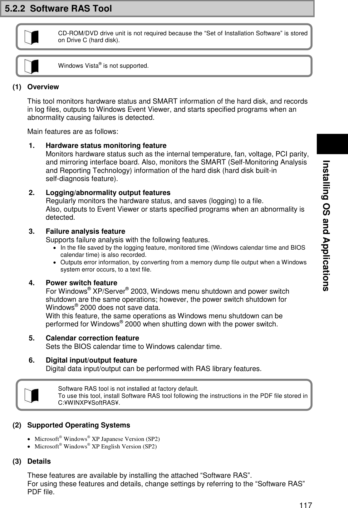
![118 5.2.3 Adobe® Reader® 7.0 (1) Overview Display, view, and print electrical manuals in PDF (Portable Document Format) format. When using Adobe® Reader® 7.0 for the first time after installation, the “Software License Agreement” window will appear. Click the [I agree] button. When adding or removing application software, make sure to log in as a user with Administrator right. When adding another application after setting up again, make sure to restart Windows before adding another application. Read [Start] [Programs] [Supplemental] before adding or removing application software. (2) How to Install 1. Start Windows. 2. Insert the included “Recovery DVD-ROM Media” into the CD-ROM/DVD drive. 3. Click [Start] [Run]. 4. For Japanese version: Enter “C:¥WINXP¥AdbeRdr¥JPN¥AdbeRdr70_jpn_full.exe” for [Name], then click the [OK] button. For English version: Enter “C:¥WINXP¥AdbeRdr¥ENU¥AdbeRdr70_enu_full.exe” for [Name], then click the [OK] button. 5. Click the [Next] button when the [Adobe Reader 7.0 Setup] window appears. 6. Click the [Next] button when the [Welcome to Adobe Reader 7.0-Japanese Setup] window appears. 7. Click the [Next] button when the [Destination Folder] window appears. To change the installation destination folder, click the [Change Destination Folder...] button, select the folder to install from the [Look in:] window, then click the [OK] button. 8. Click the [Install] button when the [Ready to Install the Program] window appears. 9. Click the [Finish] button when the [Setup Completed] window appears. The installation of Adobe® Reader® 7.0 is completed. CD-ROM/DVD drive unit is not required because “Set of Installation Software” is stored on Drive C (hard disk). This software is not included with Linux Pre-installation models. Adobe® Reader® 7.0 is not installed at factory default. To use, install Adobe® Reader® 7.0 by referring to “How to install” below. An Administrator right is the right of administrators to mange the entire computer configuration. If you are not sure how to log in as a user with Administrator right, in the [Logon Information] window, enter “Administrator” for the username, enter the Administrator account password set when the computer started for the first time for [Password], and select the computer name set when the computer started for the first time for [Domain Name], then click the [OK] button. The domain name is displayed only when the domain was set for network installation.](https://usermanual.wiki/NEC/FC-N22A/User-Guide-987184-Page-118.png)
![119 Installing OS and Applications (3) How to start Click [Start] [Programs] [Adobe Reader 7.0]. Adobe® Reader® 7.0 window appears. (4) How to delete 1. Start Windows. 2. For Windows® XP: Click [Start] [Control Panel]. 3. For Windows® XP: Double-click [Add/Remove Programs]. 4. Click “Adobe Reader 7.0” then click the [Remove] button. 5. Click the [Yes] button when the [Confirm File Delete] window appears. 6. Click the [No to All] button when the message “Delete Shared File?” appears. 7. For Windows® XP: Click the [Yes] button to restart the computer when a window prompting to restart the computer appears. Adobe® Reader® 7.0 deletion is completed. 5.2.4 Fingerprint authentication utility (only models with this feature) Fingerprint authentication is a system that authenticates a user according to fingerprint by use of a fingerprint sensor. The fingerprint authentication allows the following features to be executed: To logon Windows and cancel the lock of screen saver A replacement password for an application (Protection of the important files) (1) Supporting OSs Microsoft Windows XP, English Ver. (SP2) (2) Installation procedure 1. Start Windows. 2. Click [Start] [Control Panel]. 3. Double-click [Add or Remove Programs]. 4. Click [CD or Floppy] on the [Add new Programs] tab. 5. If message “Install Program From Floppy Disk or CD-ROM, and then click Next.” appears, click [Next]. 6. Click [Browse…] and change the file type to [Program]. Specify “C:¥WINXP¥Fingerprint Sensor¥autorun.exe” and click [Open]. 7. The menu window appears. Click [Software Installation]. 8. Follow the directions on the window. For details of installation, see “C:¥WINXP¥FingerprintSensor¥doc¥0411¥Manual.pdf”. 9. After the installation is completed, reboot N22A. Now the Fingerprint Authentication Utility is completely installed. This function does not come with Linux preinstalled models. For how to register fingerprints and how to use, refer to the following document. “Click C:¥WINXP¥Fingerprint Sensor¥autorun.exe and browse Manual.pdf.” To browse the documentation file, Acrobat Reader 7.0 must be installed.](https://usermanual.wiki/NEC/FC-N22A/User-Guide-987184-Page-119.png)
![120 (3) Usage 1. Start Windows. 2. Click [Start] [Settings] [Control Panel]. 3. Double-click [Add or Remove Program]. 4. Click [CD or Floppy] on the [Add new Programs] tab. 5. If message “Install Program From Floppy Disk or CD-ROM, and then click Next.” appears, click [Next]. 6. Click [Browse…], specify “C:¥WINXP¥Fingerprint Sensor¥autorun.exe” and click [OK]. 7. The menu dialog box appears. Click [Documentation]. Open “Manual.pdf” to check usages including the fingerprint registration procedure. (4) Deletion procedure 1. Start Windows. 2. Click [Start] [Settings] [Control Panel]. 3. Double-click [Add or Remove Program]. 4. Click [Protector Suite QL] and [Change]. 5. Follow the directions on the dialog box to uninstall the fingerprint authentication utility. 6. After the uninstallation is completed, reboot N22A. Now the fingerprint authentication utility is removed completely. Data saved in the biometric device (chip for fingerprint sensor) is not erased even if the built-in HDD is erased. See “C:¥WINXP¥Fingerprint Sensor¥doc¥0411¥Manual.pdf” to uninstall the fingerprint authentication utility in the proper procedure.](https://usermanual.wiki/NEC/FC-N22A/User-Guide-987184-Page-120.png)
![121 Installing OS and Applications 5.2.5 Infineon Security Platform Using Infineon Security Platform allows electronic mails and files to be encrypted and prohibited from being opened without authentication password. In addition, N22A is equipped with a security chip called TPM (Trusted Platform Module) in its major part to store encryption keys in the security chip. Thus, if only the HDD is withdrawn, the data in the HDD will not be read. (1) Supporting OSs Microsoft Windows XP, English Ver. (SP2) (2) BIOS setting procedure Set BIOS in the following procedure. 1. After power-on of N22A, the BIOS start screen (with NEC logo displayed at the center) appears. If message “Press <F2> to SETUP or Press <F12> to Network boot.” appears, press F2. 2. After the BIOS SETUP Utility menu appears, select [Security]. 3. Select [Security Chip Configuration] and press Enter. 4. Select [Security Chip] and press Enter. 5. Select [Enabled] and press Enter. 6. Item [Security Platform] appears. Select it and press Enter. 7. Select [Enabled] and press Enter. 8. Press F10 to open the [Save configuration changes and exit now?] dialog box. Select [Yes] and press Enter. An attempt is made to restart BIOS. 9. After restarting, the [Physical Presence Operations] dialog box is opened. 10. Select [Execute] and press Enter to try to restart BIOS. For details of the features, operations and restrictions of the Infineon Security Platform, see “C:¥WINXP¥TPM¥Readme¥JP¥Readme.txt”. To use the security chip, set supervisor and user passwords to restrict accessing to the BIOS SETUP Utility. See “SECURITY MENU” in “Chapter 4 Setting BIOS”.](https://usermanual.wiki/NEC/FC-N22A/User-Guide-987184-Page-121.png)
![122 (3) Installation procedure 1. Start Windows. 2. Click [Start] [Settings] [Control Panel]. 3. Double-click [Add or Remove Program]. 4. Click [CD or Floppy] on the [Add new Programs] tab. 5. If message “Install Program From Floppy Disk or CD-ROM, and then click Next.” appears, click [Next]. 6. Click [Browse…], specify “C:¥WINXP¥TPM¥Setup.exe” and click [OK]. 7. If [Infineon TPM Integration SDK- InstallShield Wizard] appears, click [Next]. 8. Install the Infineon Security Platform according to the directions on the screen. 9. If the installation is completed and the message prompting you to reboot N22A, click [Yes] to reboot it. Now the Infineon Security Platform is installed completely. (4) Starting procedure The [TPM] icon appears on the task tray at the bottom right corner of the screen. Click the icon to display its menu. (5) Deletion procedure 1. Start Windows. 2. Click [Start] [Control Panel]. 3. Double-click [Add or Remove Programs]. 4. Click [Infineon TPM Professional Package] and [Change/Remove]. 5. If the [Confirm File Deletion] dialog box appears, click [Yes]. 6. When [Delete shared file?] appears, click [No to all]. 7. After the uninstallation is completed, reboot N22A. Now the Infineon Security Platform is deleted completely. After the installation, select [Security Platform Initialization] and [Security Platform User’s Initialization] on the menu displayed by selecting the TPM icon. Then select [Manage Security Platform] to set security features. Just after BIOS setting, the hardware add wizard requests driver installation. However, the driver can be installed in the following procedure. you may cancel the hardware add wizard.](https://usermanual.wiki/NEC/FC-N22A/User-Guide-987184-Page-122.png)
![123 Installing OS and Applications 5.2.6 FC Button Setting Tool Two sets for executing desired applications can be registered to abbreviation keys. (1) Supporting OSs Microsoft Windows XP, English Ver. (SP2) (2) Usage The registered applications can be executed by Fn+1 (FC button 1) and Fn+2 (FC button 2), respectively. The tablet buttons at the lower left corner of the LCD display can be assigned new features different from their original ones by using the BIOS SETUP Utility. If any of the keys are assigned [FC button 1] and/or [FC button 2], the execution commands (or application starts) registered on the [FC Button Setup utility] dialog box can be run. FC button 1 and FC button 2 must be assigned to tablet buttons via the BIOS setup menu to use the above function. See C:¥WINXP¥FCBTN¥FCbtnReadme.txt for details. (3) Start procedure Click [Start] [All Programs] [FC Button Setup utility]. The [FC Button Setup utility] dialog box shown below appears. Set the buttons appropriately. For BIOS settings, see “Chapter 4 Tablet Button Submenu”.](https://usermanual.wiki/NEC/FC-N22A/User-Guide-987184-Page-123.png)
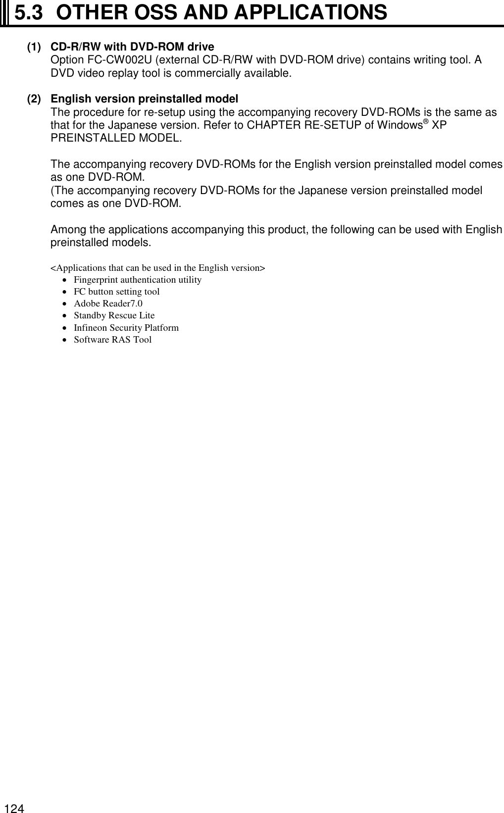

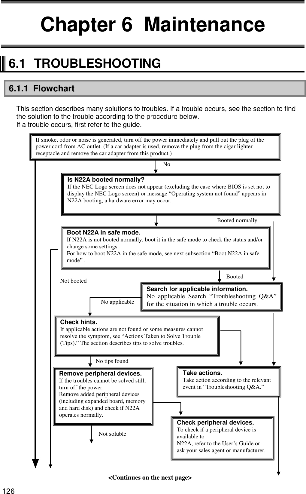
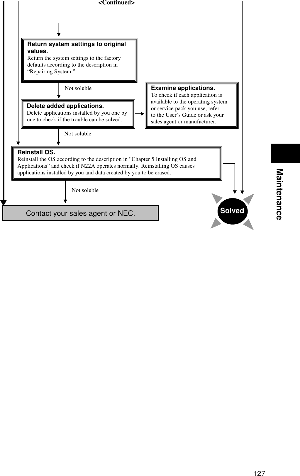
![128 6.1.2 Actions Taken to Solve Trouble (Tips) Because N22A uses combinations of various applications and peripherals, unexpected troubles can occur. The following describes tips to solve troubles appropriately. Take proper actions calmly. Neither turn off the power nor click the mouse hastily. If N22A seems to freeze, it may only take much time to process applications. If so, wait for a while until the processes are completed. Write down message on screen if displayed. Put numeric and English messages on paper because such ambiguous information can often be good tips for solving troubles. Guess cause of trouble. Guess which device caused the trouble among N22A, a peripheral device, an application or another. The cause may not be identified. However, you can easily take proper action if identified. If the trouble may possibly be caused by a peripheral device, remove the peripheral devices one by one and re-execute the operation in which the trouble occurred. Then you may identify the peripheral device causing the trouble. Boot N22A in safe mode If N22A is not booted normally, boot N22A in the safe mode to check the status and/or change settings properly. See “Starting Windows XP in Safe Mode” in “Repairing System”. Use system information System information You can collect the system information including the configuration of N22A and other related information can be collected to display the information. The system information helps to search for the data required to solve system problems rapidly. - Procedure of displaying [System Information] dialog box. Click [Start] [All Programs] [Accessories] [System Tools] [System Information]. System restoration You can cancel improper changes of N22A to return to the default settings. See the help of Windows for details. See Windows help. Help start procedure Click [Start] [Help and Support] to display the [Help and Support Center] dialog box. Trouble solving procedure: - Search for tips by “Fixing a problem” The following operation allows tips to be displayed to solve problems depending on situations of N22A. 1. Click [Fixing a problem] in the [Help and Support Center] dialog box. Topics for solving problems appear. 2. Click the topic you want to see. The details of the selected topic appear on the right window. 3. Click an item you want to see from the list in the window. The causes and solutions of the trouble appear in the right window. Take actions according to the directions on the screen.](https://usermanual.wiki/NEC/FC-N22A/User-Guide-987184-Page-128.png)
![129 Maintenance Some items may list trouble situations on the right window. In such a case, click the applicable situation to select it and click [Next] at the bottom of the window. The possible causes and resolutions of the trouble appear on the right window. - Search for desired items by keywords The following procedure allows you to specify keywords of desired items to search for tips. 1. Enter a keyword to be checked in the [Search] field of the [Help and Support Center] dialog box. 2. Click [] next to the [Search] field. Related topics appear. 3. Select an item from the topics to click it. The description of the item appears on the right window. Search “Troubleshooting Q&A” for applicable trouble. Read the applicable item if found. See other guides, helps and README files. If a trouble occurs in an application, refer to the User’s Guide or help of the application. README files are often provided for applications to include important information which is not descried in respective user’s guides and helps. Open the relevant README file by using a text editor such as Notepad to see the file. Recover system settings to original. You can return the system settings to the factory default values in the following procedure: 1. Turn on the power of N22A. 2. Press F2 on the NEC Logo screen. The BIOS Setup Utility Menu screen appears. 3. Press F9. The confirmation message appears. 4. Confirm that [Yes] is selected and press Enter. 5. Press F10. The confirmation message appears. 6. Confirm that [Yes] is selected and press Enter. For details of BIOS setup, see “Chapter 4 Setting BIOS”. Restore system. If Windows does not start at all, see “Re-setup” in this chapter to restore the system. Contact NEC. For NEC inquiries, see “Maintenance Service” in this chapter. Before inquiring, enter the failure symptoms on the “Problem Check Sheet” at the end of this manual. The warranty card includes the model number and other information useful for remedies, so have it handy for reference. For troubles on a peripheral, memory device or application purchased separately, contact the agent of the product. For troubles of an application attached to N22A, the agent of the application can give proper responses. Clicking [Set search options] below the [Search] field allows desired information to be retrieved from other information sources.](https://usermanual.wiki/NEC/FC-N22A/User-Guide-987184-Page-129.png)
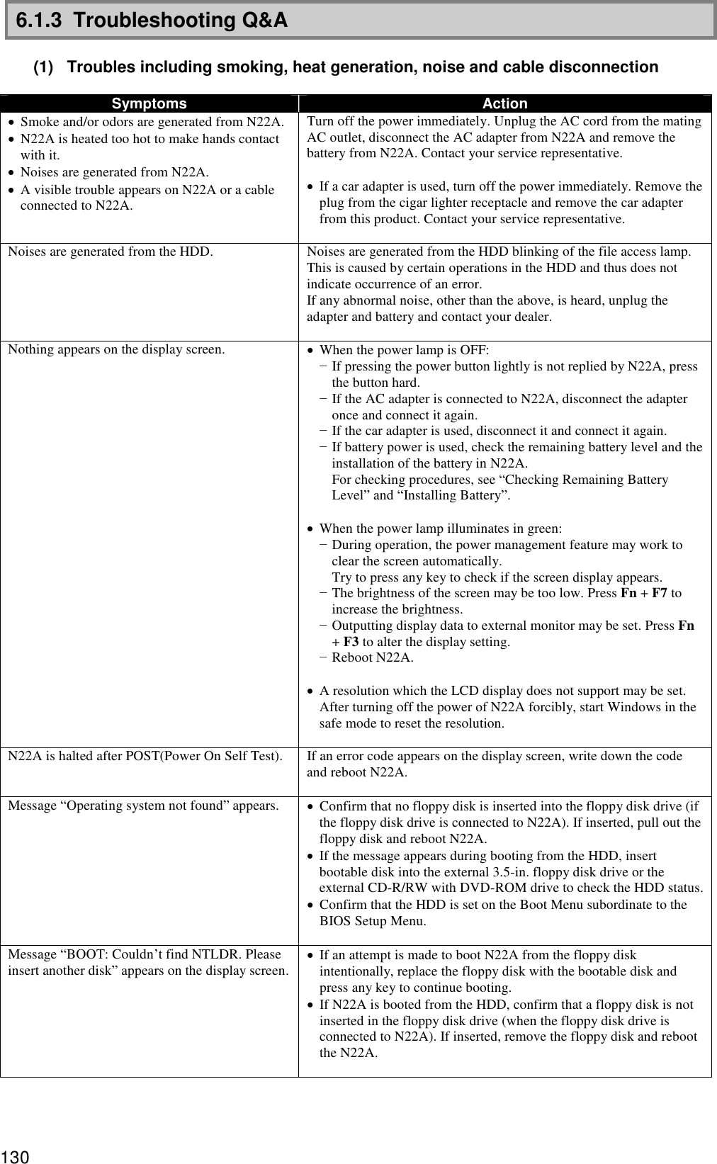
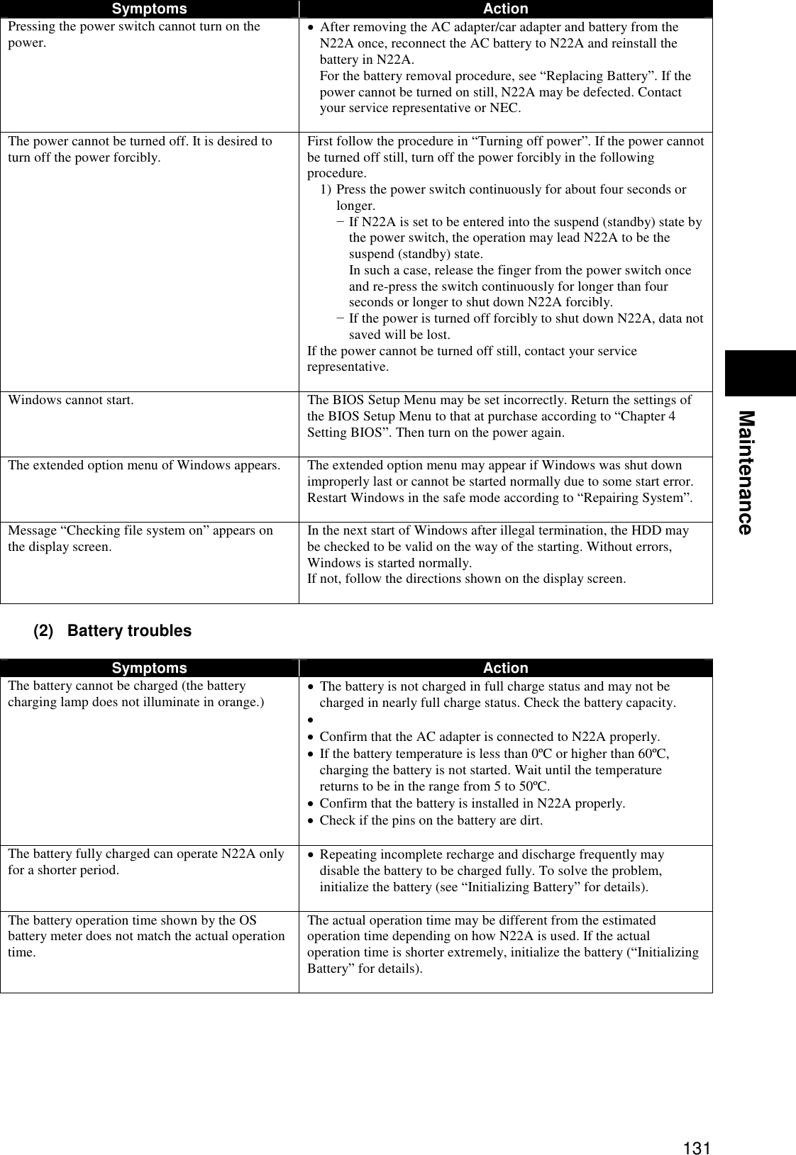
![132 (3) AC adopter troubles Symptoms Action Power is not supplied even though the AC adapter is connected. The power lamp blinks red. It is the voltage error if the power lamp is blinking in red and green alternately at 0.5-second intervals. Stop using the AC adapter and contact your dealer. (4) Display troubles Symptoms Action The screen is dark considerably. Adjust the brightness by using Fn + F7 or the relevant tablet button. The resolution cannot be adjusted to the desired value. Confirm that the video driver is installed properly. Check the BIOS Setup Menu to confirm that the video memory is configured properly. If an external monitor is used, confirm that the monitor supports the desired resolution. Nothing appears on the external monitor. Confirm that the power of the monitor is ON. Confirm that the monitor signal cable is connected properly. Change the selected monitor to the external one by pressing Fn + F3 or through the Windows [Display] roperty. The concurrent display feature does not operate. Turn on the power of the external monitor before turning on the power of N22A. Select the desired display option by pressing Fn + F3 or through the Windows [Display] property. Windows cannot be started after BIOS setting is changed. In the next start of Windows after illegal termination, the HDD may be checked to be valid on the way of the starting. Without errors, Windows is started normally. If not, follow the directions shown on the display screen. The original screen before entering into the power saving state does not appear. Some applications or peripheral devices may operate improperly when an attempt is made to use the suspend (standby) feature. Turn off the power of N22A once and on again. If the power cannot be turned off, press the power switch continuously for four seconds or longer to shut down N22A forcibly. To use an application or peripheral device of such type, do not enter N22A into the suspend (standby) state. The command prompt (MS-DOS prompt) window appears on the full screen. Press Alt + Enter. With the command prompt (MS-DOS prompt) being active, the screen does not appear after recovery from the suspend (standby) state. Press Alt + Tab to alter the task. Then N22A operates normally. The LCD brightness is lowered when using the N22A in a high–temperature environment. When using the N22A in a high-temperature environment while the LCD brightness is set to high for a long period of time, the internal temperature may rise. In such a case, the LCD brightness is automatically lowered or cannot be raised, to extend the LCD life. (5) Troubles of hardware devices Symptoms Action N22A does not recognize a device newly installed. The devices may be configured improperly on the BIOS Setup Menu. Confirm that the used peripheral port is set to [Enabled] on the BIOS Setup Menu. Check if the relevant device driver should be installed. Check if the device requires one or more jumper and/or switch settings. For an external device, check if the connection cable such as a USB cable and the power cord are connected properly. If the external device has its own power switch, confirm that the power is turned on.](https://usermanual.wiki/NEC/FC-N22A/User-Guide-987184-Page-132.png)
![133 Maintenance (6) Troubles of HDD Symptoms Action After power-on, N22A does not recognize the HDD. Confirm that the type of the HDD is configured properly on the BIOS Setup Menu. An error message on the HDD appears on the display screen. Insert the bootable disk to the external 3.5-in. floppy disk drive or the CD-R/RW with DVD-ROM drive to check the consistency of the HDD. The HDD may possibly be defected. Contact your service representative. The HDD can operate only slowly. Data files stored in the HDD may be fragmented. Optimize the files by using such a tool as Windows defragmenter. The indicator indicating use of the HDD does not blink but remains ON. Data files stored in the HDD may be fragmented. Cancel the file fragmentation by using such as tool as Windows defragmenter. The empty capacity in the HDD is not enough. The empty capacity in the HDD can be increased in the following ways: − Delete all files in the Recycle Bin. − Reduce the maximum size of the Recycle Bin. (If the maximum size of the Recycle Bin is set to 0%, deleted files are rejected without storage in the Recycle Bin.) − Deletes contents in the TEMP folder. (Do not delete the primary working file while one or more applications are executed. Deleting the primary working file may cause applications not to operate.) − Delete temporary files for Internet Explorer. − Delete one or more installed applications. (Deleting applications not used at the moment allows the empty capacity in the HDD to be increased.) − Click [Disk Cleanup] to delete unnecessary files in the HDD. The empty capacity in the HDD does not increase after unnecessary files are dumped into the Recycle Bin. Files deleted or drugged to the Recycle Bin are not deleted from the HDD immediately but stored in the Recycle Bin. To delete files stored in the Recycle Bin from the HDD, right-click the Recycle Bin icon to display the menu and click [Empty Recycle Bin] in the menu. (7) Troubles in file storage Symptoms Action Data cannot be stored in the HDD. Check the empty HDD capacity. If not enough, increase the empty capacity according to “Empty HDD capacity is not enough” on [Hard Disk]. Any file larger than the empty disk capacity cannot be saved. Data cannot be stored in the floppy disk. Check if the floppy disk is subjected to write-protect. If so, release the write-protect. Check the empty capacity of the disk. If the empty capacity is not enough, reject unnecessary files or use another floppy disk. Data cannot be stored in the SD card. Check if the write-protect switch on the SD card is set to [LOCK]. If so, release it.](https://usermanual.wiki/NEC/FC-N22A/User-Guide-987184-Page-133.png)
![134 (8) Troubles of keyboard, mouse and touch pad Symptoms Action The keyboard does not respond to any inputs. Connect an external USB keyboard to N22A and check if the keyboard can operate properly. If so, the built-in keyboard cable may be defected. Contact your service representative. The numerical keypad is disabled. Confirm that [Num Lk] is ON (the NumLk LED illuminates in green). The external USB keyboard and/or USB mouse do not operate. Check if the USB cables are connected properly. The serial mouse does not operate. Confirm that the mouse cable is connected properly. Connect the mouse before booting N22A. Confirm that the serial port is enabled on the BIOS Setup Menu. The touch pad does not operate or makes responses only slowly. Check if the touch pad is dirt. If operated by excess force or other than finger cushions, the touch pad may operate improperly. If you touch more than one point, the touch pad does not operate normally. The touch panel does not operate or the pointer operates invalidly. Confirm that the driver and utility software of the touch panel are installed. Calibrate the touch panel by using the utility software. (9) Troubles of network (LAN) Symptoms Action N22A cannot connect with network. The connection may be invalid. Contact your network administrator to check if N22A is connected to the relevant hub through a LAN cable. The setting may be invalid. For example, the protocol or the domain work group may be set improperly or the computer account may not be put on the primary domain controller. For details, ask your network administrator. Only the [Whole Network] icon appears in the [My Network] or [Network Computer] dialog box. It may take a rather long time until the display appears. Wait for a while and click [Refresh] on the [View] menu. If the display status remains unchanged, the network may be connected improperly or network software may be set inappropriately. Check the connection and network software. Only the own computer appears in the [My Network] or [Network Computer] dialog box. It may take a rather long time until the display appears. Wait for a while and click [Refresh] on the [View] menu. If the display status remains unchanged, check if the domain or work group to be connected matches the setting domain or work group. To see the setting domain or work group, click [Start] [Control Panel] [Performance and Maintenance] [System] to display the [System Properties] dialog box and select the [Computer Name] tab on the dialog box.](https://usermanual.wiki/NEC/FC-N22A/User-Guide-987184-Page-134.png)
![135 Maintenance Symptoms Action Shared drives and/or folders are unavailable. Check if the Microsoft network share service is installed in N22A by clicking [Start] [Connect To] [Show all connections] to display the LAN connection icon, right-clicking the icon, clicking [Properties] and checking column “This connection uses the following items:” in the [General] tab. If not, shared drives and folders are not available. To use them, install the share service. Check if N22A is set to access to shared drives and folders. To allow other computers connected to the network to use drives and/or folders in N22A, drives and folders to be shared should be set for share. For the purpose, right-click a drive or folder to be shared to display the menu, click [Sharing and Security ...] in the menu and check “Share this folder on the network” in the [Property] dialog box. After the setting, the drive or folder icon changes to be suit to share. Check if certain access authorities are set for shared drives and folders. The owner of a shared drive or folder can set its access authority. The access authority of a drive or folder defied to be shared is first set to “read only”. Other users can read data from the drive or folder but cannot write data to it. Pressing F12 cannot make network booting. Pressing F12 on the NEC logo screen may not be able to run the network boot process. In this case, press F12 on the NEC logo screen several times. If the network boot process is not executed still, change the interval at which F12 is pressed. N22A operates only unstably. state during communication, N22A may operate improperly. Do not enter N22A into the suspend (standby) or pause state during communication. Release the setting that the Windows power management feature may enter N22A into the suspend (standby) state automatically if the setting is provided. (10) Troubles of wireless LAN Symptoms Action Communication is disabled. Check that the wireless communication switch is on. Press Fn + F2 to alter ON/OFF of the wireless LAN feature. On the [Wireless Network Connection Status] dialog box, [Disable] of the wireless LAN feature may be checked. Click [Start] [Connect to] [Wireless Network Connection] to check the setting. Check if the power of devices to be connected are turned on according to the User’s Guides of the devices. Confirm that the SSID (network name) is set properly. To connect to a wireless LAN access point, set the SSID to be the same as the ID of the access point. With data encryption, confirm that the encryption key is set correctly. Set a specific encryption key for all wireless LAN access points and computers connected to N22A. Check if the environment is set properly. Set the environment again if necessary. Communication is disabled intermittently or the communication speed is too late. The wireless LAN device to be connected may be located too far from N22A. Check the radio wave environment. In poor radio wave environment, make the wireless LAN device close to N22A. The possible distance between N22A and a wireless LAN device varies depending on device specification. If one or more wireless devices only conforming to IEEE802.11b exist in a range where radio wave can be radiated to a connected wireless LAN access point conforming to IEEE802.11g, the communication speed for IEEE802.11g decreases. If a wireless device only conforming to IEEE802.11b connects to another access point, only reach of radio wave to the access point influences the communication speed.](https://usermanual.wiki/NEC/FC-N22A/User-Guide-987184-Page-135.png)
![136 Symptoms Action Communication is disabled intermittently or the communication speed is too late. If a microwave oven is used in an area where communication with 2.4 GHz wireless LAN device occurs, the communication speed and distance of the 2.4 GHz wireless LAN device may be reduced. It is recommended that microwave ovens are not used near 2.4 GHz wireless LAN devices. Concurrent communication of 2.4 GHz wireless LAN and Bluetooth devices may decrease the communication speed and/or distance of devices of each type. It is recommended not to operate either 2.4 GHz wireless LAN or Bluetooth devices or keep them away from each other. If more than one computer are connected to a network, increase in the number of computers connected to a single wireless LAN access point may cause the transmission speed per computer to decrease. A remote computer does not appear in [Network Computer]. Check computer names. A computer connected to N22A may have the same name. Give a unique name to N22A. If a remote computer does not have the “File and Printer Sharing for Microsoft Network” service, the PC does not appear in the [Wireless Network Connection Properties] dialog box. Install the service in the remote computer. Check if the TCP/IP protocol is installed in N22A. Set the IP address properly to be appropriate for the network connected. The surrounding radio wave status may be bad. Shorten the distance to the remote computer connected to N22A and/or remove obstacles between N22A and the remote PC. Then connect N22A to the remote device again. The remote computer may be just booted. After several minutes, check the connection status again. Double-clicking the icon of a remote computer in [Network Computer] cannot indicate the information on the PC. Check if shared folders and printers exist in remote computers. Set folders and printers to be shared on remote computers to “Sharing and Security...”. Connection with an access point is cut off without notice. If more than one access point exist in the surrounding area, the connection is automatically switched to another access point depending on settings of access points. If another access point uses the same SSID (network name), change the SSID. A wireless LAN cannot be used prior to log on to Windows. Enable “Before log-on/common: active while a user is logging on. All users share this profile” of management profile type for wireless LAN setting. For how to set, refer to CHAPTER 2 USING THIS PRODUCT WIRELESS LAN. (11) Bluetooth-related failure Symptoms Action Communication is not possible. Make sure the wireless communication switch is on. Check whether the Bluetooth function is disabled in the Wireless network connection. If it is disabled, enable the function. Communication disconnects. Connect the line again. Disconnection of communication takes long. It may take much time to disconnect Bluetooth devices.](https://usermanual.wiki/NEC/FC-N22A/User-Guide-987184-Page-136.png)
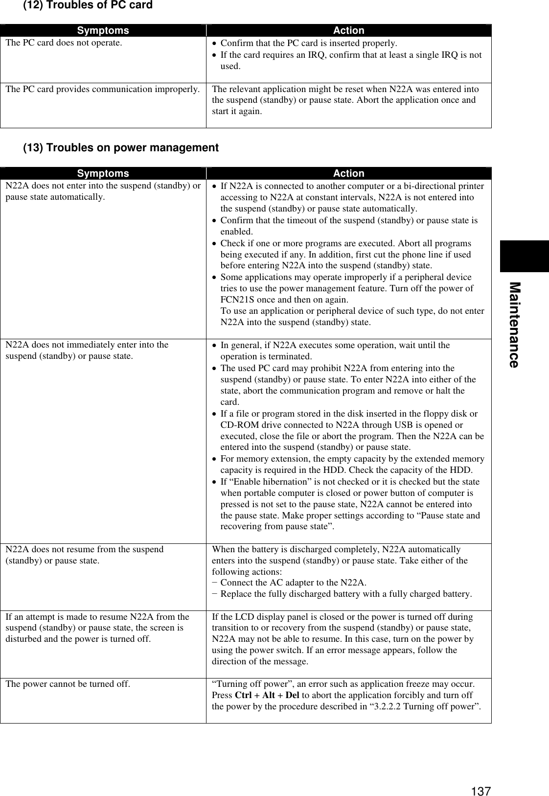
![138 (14) Software troubles Symptoms Action An application program operates improperly. Confirm that the application program is installed properly. If an error message appears on the display screen, refer to the documentation of the application program to search for required information. If N22A is shut down clearly, reboot N22A. <Resetting N22A> If an error occurs to cause programs being used to hang, N22A may have to be reset (rebooted). If N22A seems to hang, wait for a while. N22A may provide data processing. Check the LED indicating use or no use of the HDD periodically. If the LED blinks irregularly, programs may access to the HDD to disable the keyboard. When N22A does not operate at all and the “Restart” feature of OS is unavailable, reset N22A. Follow the procedure below to reset N22A: 1. Press Ctrl + Alt + Del. 2. If the above step does not work well, continue to press the power button for four seconds or longer to shut down N22A. Wait for five seconds or longer and turn on the power of N22A again. The reset operation erases all data not stored. (15) Sound troubles Symptoms Action Sound does not replay. Check if the mute feature is enabled. Click [Start] [Control Panel] [Sounds, Speech and Audio Devices] [Sounds and Audio Devices] to display the [Sound and Audio Devices Properties] dialog box. If the [Mute] checkbox in the [Volume] tab of the [Sound and Audio Devices Properties] dialog box is checked, uncheck the checkbox. Confirm that the volume level is not set to too low. The volume may often be too low. Press Fn + F9 to turn up the volume. Confirm that the sound driver is installed properly. Confirm that N22A is not in the suspend (standby) state. If external speakers are used, confirm that they are connected to N22A properly. Sound is replayed but distorted. Confirm that the volume is set to neither too high nor too low. In most cases, because the volume is set to too high, some electronic audio parts lead sound distortion. The sound system fails in recording. Adjust the replay or record sound level. An external microphone or sound device does not operate. Confirm that a microphone is connected to the mating connector on N22A properly. Click the speaker icon on the task bar to check the Windows volume. Check the volume control of N22A.](https://usermanual.wiki/NEC/FC-N22A/User-Guide-987184-Page-138.png)
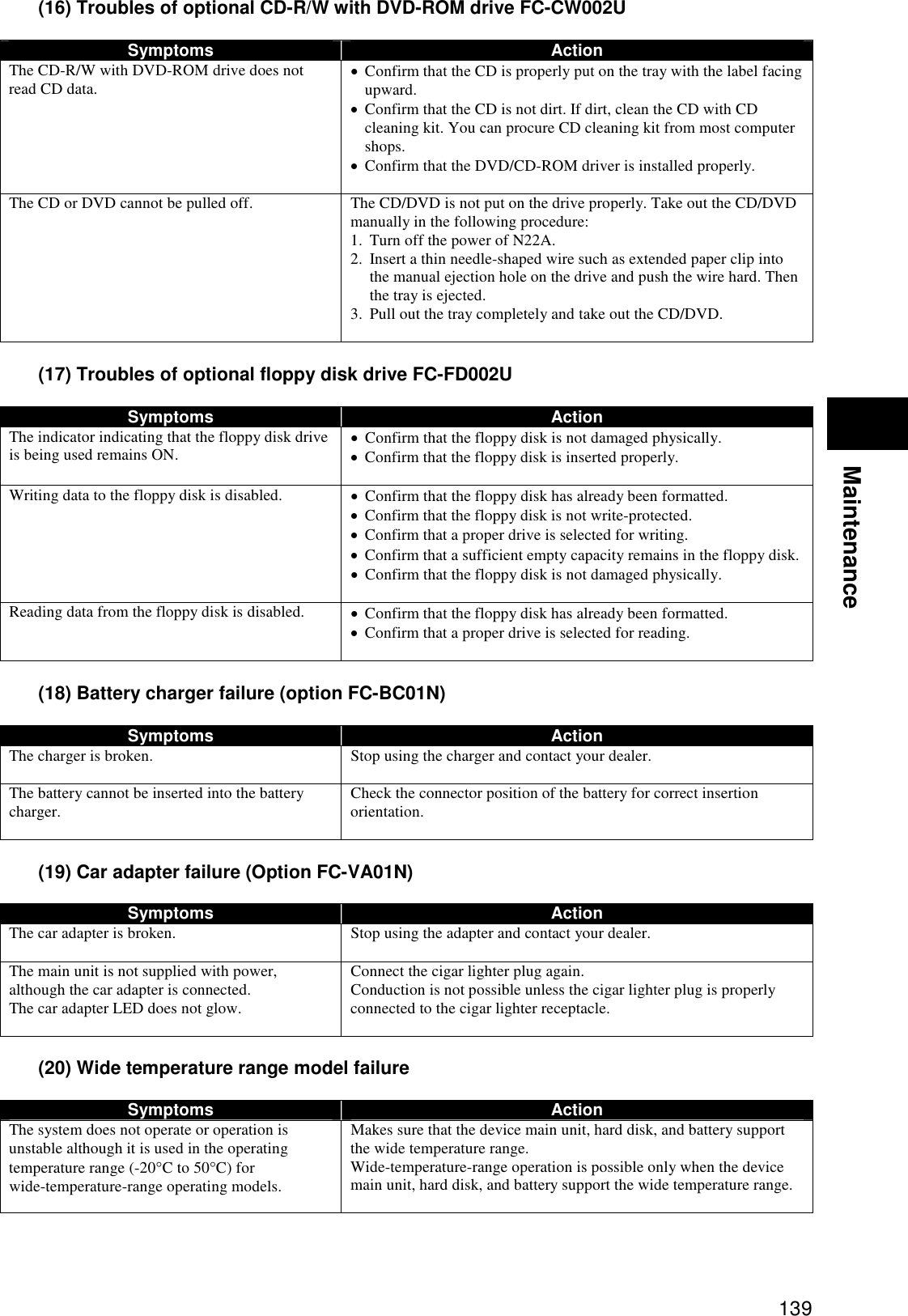
![140 (21) Password troubles Symptoms Action After password entry, message “An invalid password is entered” appears. Check the password again and reenter it properly. Check if the [Caps Lock] or [Num Lock] key lamp illuminates. If the [Caps Lock] or [Num Lock] key lamp illuminates, the password may be unable to be entered properly. If [Caps Lock] key lamp illuminates, press Shift + Caps Lock to release it. Then enter the password. If [Num Lock] key lamp illuminates, press Fn + F12 to release it. Then enter the password. The password is forgotten. If you forget the Windows password, there is no means to find the password directly. Take any of the following actions: − Click to the right of the “type your password” field on the Windows logon screen to check the tip of the password. − Logon to N22A with another user account. − Ask a person having an administrator account of N22A to create a new password. If you forget the supervisor password, contact your service representative. (22) Miscellaneous Symptoms Action The date and/or clock go wrong. If the device is stored at a high or low temperature, the internal clock may deviate. In this case, reset before use. Check the clock of OS and the BIOS Setup Menu to find the system time (OS) and the RTC clock (BIOS). When the system time goes wrong: The operated application software may be defected. Abort the software and set the date and time again. If the system time goes wrong still, contact your service representative. When the RTC time (BIOS) goes wrong: The power of the calendar clock built in N22A is supplied by a battery. Accordingly, the calendar clock can continue operating if the power of N22A is turned off. If the date and/or time go wrong after resetting, the backup battery may reduce its necessary level or a hardware error may occur. Contact your service representative. It is desired to use N22A in other than Japan. Contact your service representative. NEC does not provide any maintenance service in countries and regions other than Japan.](https://usermanual.wiki/NEC/FC-N22A/User-Guide-987184-Page-140.png)
![141 Maintenance 6.2 RE-SETUP OF Windows XP IN N22A OF PRE-INSTALLED MODEL 6.2.1 Re-setup Re-setup can recover the damaged system of N22A to the normal state. However, files stored in the HDD are erased. In addition, it takes much time for re-setup. Check if re-setup is absolutely required before starting the job. (1) Situations requiring re-setup Provide re-setup for the system in N22A in the following situations: 1. Recovering system from trouble At power-on, the power lamp goes on but Windows does not start. One or more programs in the HDD do not operate. System files in the HDD are erased unintentionally. Repairing the system cannot solve problem. Started Windows XP in the safe mode, but problem cannot be solved. 2. Changing settings of Windows The settings of Windows are required to be recovered to the factory defaults. 3. Changing the settings of the HDD The capacity of drive C is required to be changed. The HDD is required to be configured with only a single partition. (2) System repair procedure The system can be repaired in either of the following two ways. The proper way is dependent on the system status. Try the simpler method first in the order shown below: 1. Repair the system by using the [Last Known Good Configuration] menu. 2. Provide the system with re-setup by using the recovery CD-ROMs. Notes on re-setup Make a backup of data. Some re-setup methods may erase all or a part of data you have created. For the re-setup methods, see “Standard and Custom Re-setups”. Write down the settings of N22A. Re-setup returns all settings including network settings to the factory defaults. To use N22A with the same settings as the current ones after re-setup, write down the current settings of N22A. Remove peripheral devices purchased separately from N22A. Provide re-setup under the condition that devices coming with FC-N21C are only connected to N22A. Peripheral devices purchased separately should be connected to N22A after re-setup. If a supervisor password is set, cancel the supervisor password or change the BIOS SETUP as follows: Select [Security] [Password on boot] [Disabled]. For the supervisor password, see “Chapter 4 Security”. Do not suspend re-setup. After starting re-setup, be sure to complete it according to the procedure described in this guide. If suspended, restart the re-setup from the beginning. The re-setup is to return the system in N22A to that in the same state at shipment from factory based on the data stored in the recovery CD-ROMs if the system is damaged. The re-setup is also required after the configuration of the HDD is changed. It is because formatting (initializing) the HDD causes the system to be erased.](https://usermanual.wiki/NEC/FC-N22A/User-Guide-987184-Page-141.png)
![142 6.2.2 Standard and Custom Re-setups There are two re-setups, or standard and custom re-setups. The following describes four re-setup patterns. (1) Standard re-setup Every hard disk drive in N22A can be returned to the factory default. Beginners and users unfamiliar with HDD should always follow the procedure for re-setup. (2) Custom re-setup For re-setup of drive C only or change of the capacity of drive C, follow the procedure. Select any of the following three procedures and go to Subsection “Custom Re-setup”. 1. Re-setup of drive C only in the NTFS format. Provide only drive C in the built-in HDD with re-setup in the NTFS format. Drive D and the other drives are not formatted and the data in the drives is left as it is. * The capacity of drive C is not changed. 2. Re-setup of entire HDD area to a single partition Provide the entire area of the built-in HDD with re-setup to a single partition in the NTFS format. Drive C can have the maximum capacity. Data in the built-in HDD is erased completely. Be sure to make backup copy of the data. 3. Free re-setup of HDD area (re-setup by user setting) Provide the area of the built-in HDD with re-setup to a combination of partitions of 5GB or larger in 1GB freely. Data in the built-in HDD is erased completely. Be sure to back up the data. For file systems NTFS, FAT32 and FAT16, click [Start] [Help and Support]. (Searching with keyword such as “File System”, you can view the detailed information.)](https://usermanual.wiki/NEC/FC-N22A/User-Guide-987184-Page-142.png)
![143 Maintenance 6.2.3 Repairing System The following describes the troubleshooting procedures when the system cannot be started normally due to change of system configuration. Repairing System by Using Configuration in the Last Normal Starting If starting Windows XP is disabled after some system change, the problem can be solved by using the configuration in the last normal starting. The configuration changes made after the last normal starting are all discarded. If the system is started normally more than once after configuration change, the configuration before the change cannot be recovered. To use the configuration on the last normal starting, follow the procedure below: 1. Start Windows XP being defected. 2. If message “For troubleshooting and advanced startup options for Windows, press F8.” appears on the screen, press F8. 3. If [Windows Advanced Options Menu] appears, select [Last Known Good Configuration] and press Enter. 4. On the operating system selection menu, press Enter. The [Hardware Profile/Configuration Recovery Menu] dialog box appears. Any of the following options can be selected on the menu. Hardware profile selection used at startup of this device Switch configuration at previous normal startup Reboot this device System repair 5. To restart Windows XP in the configuration before occurrence of the problem, press L. Then press Enter. Windows XP is started by using the configuration at the last normal starting. Starting Windows XP in Safe Mode The safe mode is a specific diagnostic mode intended to allow Windows to be started normally. Follow the procedure below to start Windows in the safe mode: 1. Start Windows XP. 2. If message “For troubleshooting and advanced startup options for Windows, press F8.” appears, press F8. 3. Select start option “Safe Mode” and press Enter. Windows XP is started in the safe mode. Repairing System by Using [System Restore] If using the safe mode or the configuration on the last normal starting cannot start Windows XP normally, use [System Restore] to repair the system. This method allows N22A to be recovered to the previous state without discarding the personal data files. To start [Restore System], click [Start] [All Programs] [Accessories] [System Tools] [System Restore]. For details, click [Start] [Help and Support] to see the information. (You can search with keyword “system repair” for the detailed information to be viewed.)](https://usermanual.wiki/NEC/FC-N22A/User-Guide-987184-Page-143.png)
![145 Maintenance 4. If the following dialog box appears, select [標準再セットアップモード(強く推奨)] and press Enter. 5. Follow the direction on the dialog box to provide re-setup. For the subsequent steps, follow the directions on the dialog box. Now the HDD is completely restored to the factory defaults. Then provide re-setup for Windows XP. (5) Re-setup of Windows XP If the power of N22A is turned on for the first time after system restoration by using the recovery CD-ROMs, the Windows XP setup job including entry of your name is required. It takes about 30 minutes to complete the job. 1. Reboot N22A after the system restoration job is completed. If the [Welcome to Microsoft Windows] screen appears, click [Next]. 2. The [The End User License Agreement] screen appears. Click the scroll button to read it thoroughly. 3. After reading, click [Yes, I accept]. Then click [Next]. Clicking [No, I don’t accept] disables the setup job to be started. 4. If the [Help protect your PC] dialog box appears, select [Not right now] and click [Next]. 5. If the [What’s your computer’s name?] dialog box appears, enter any name in the name field. The factory default of [Computer name] is “FCN22A-XXXXX” (XXXXX: lowest five digits of product ID). The computer name can be changed later. [Computer description] is empty at shipment. 6. Click [Next]. 7. If the [What’s your Administrator password?] dialog box appears, enter a password in the password field. The password field is empty at shipment. The password is case sensitive. The password can be changed later. The password entered here must be reentered in the re-setup job. Take note of the password for remembrance. 8. Click [Next]. 9. If message “Is this computer in a domain?” appears, select [Yes] or [No].](https://usermanual.wiki/NEC/FC-N22A/User-Guide-987184-Page-145.png)
![146 (The following describes the operation after you select [No].) 10. Click [Next]. 11. Message “Checking your Internet connectivity” appears and then message “How will this computer connect to the Internet?” appears. 12. Click [Skip]. 13. Message “Ready to register with Microsoft” appears. 14. Select “No, not at this time” here. 15. Click [Next]. 16. If message “Who will use this computer” appears, enter a user name. Default user name: FC-USER Without entering a user name, you cannot advance to the next step. The data in [User Name 1] is registered as the user of [System Properties]. 17. Click [Next]. 18. Message “Thank you!” appears. 19. Click [Finish]. 20. Message “Please wait…” appears. Wait until the screen changes without any operation. 21. If the [Logon to Windows] screen appears, enter the password set in step 7 and click [OK]. 22. Wait until the desktop screen appears. Before the desktop screen, the [Change System Settings] screen may appear. Before the desktop screen, the [Change System Settings] screen may appear. In this case, wait until the desktop screen appears, click [Finish] on the [Introduction to Windows XP] screen and click [Yes] on the [Change System Settings Screen] screen to restart the system. Now the operation is completed. After re-booting, the [Welcome to the Found New Hardware Wizard] dialog box may appear. If this occurs, provide proper settings in the following procedure: 1. If [Welcome to the Found New Hardware Wizard] appears, click “No, not this time” and then click [Next]. 2. Click “Install the software automatically” and then click [Next]. Message “Please wait while the wizard installs the software …” appears. 3. If the [Completing the Found New Hardware Wizard] dialog box appears, click [Finish]. Because WindowsXP automatically recognizes USB keyboard and mouse, specific settings are not required. In use of a USB keyboard, [Standard 101/102 –Key or Microsoft Natural PS/2 Keyboard] or [PS/2 Compatible Mouse] may appear when you click [Start] [All Programs] [Accessories] [System Tools] [System Information] and select [Components] [Problem Devices] in the [System Information] dialog box. This is a view-only problem. The USB keyboard can operate normally without any problems. If the keyboard or mouse is reconnected, the key layout may be set improperly. If so, see “(6) Notes on change to keyboard or mouse of different key layout” described below.](https://usermanual.wiki/NEC/FC-N22A/User-Guide-987184-Page-146.png)
![147 Maintenance (6) Notes on change to keyboard or mouse of different key layout If the current keyboard or mouse is changed to another one, the new keyboard or mouse may operate improperly. If so, change the key layout of the keyboard in the following procedure: 1. Click [Start] [Control Panel]. 2. Click [Date, Time, Language, and Regional Options] and [Regional and Language Options]. 3. Click [Details…] in [Text services and input languages] of the [Language] tab. Note: If you find the desired keyboard layout in the list of installed services, go to step 7. Click [Add] in [Installed services]. 4. Select the language of the keyboard layout to be added from the [Input language:] list. 5. If [Keyboard layout/IME:] has only a single option, click the option. If more than one options are available, open pull-down menu [Keyboard layout/IME:] and select the desired option from the list. 6. Click [OK]. 7. Click the language of the used keyboard layout from the [Default input language] list. 8. Click [OK]. 9. Click [OK]. Installing Attached Applications Install attached applications with re-setup. For the re-setup procedure, see “Chapter 5 Installing Attached Applications”. Providing Settings Made after Purchase Again Any settings made after purchase are discarded by re-setup. Provide the settings again. Reconnect peripherals purchased separately if any and provide settings for the peripherals again. Also make network setting. In addition, reinstall applications purchased separately and having been installed if any.](https://usermanual.wiki/NEC/FC-N22A/User-Guide-987184-Page-147.png)
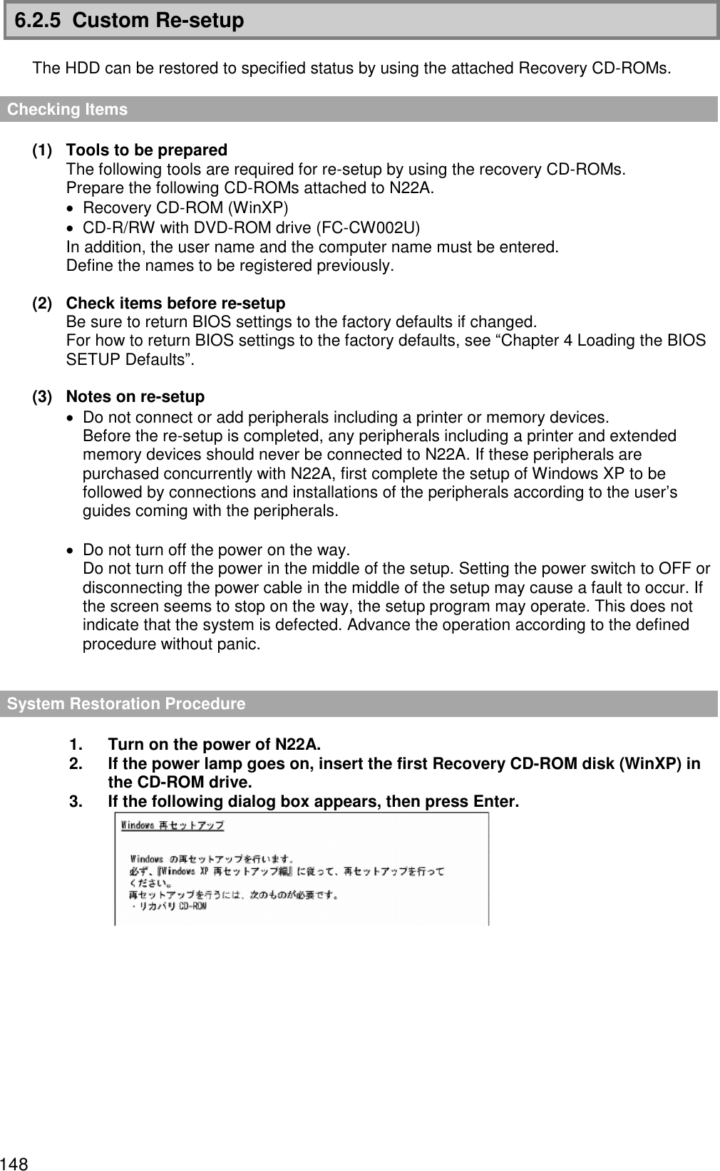
![149 Maintenance 4. If the following dialog box appears, select [カスタム再セットアップモード] and press Enter. 5. The following dialog box appears. Select one of the following three procedures. (1) [C ドライブのみを再セットアップ] (2) [全領域を 1 パーティションにして再セットアップ] (3) [ユーザ設定による再セットアップ] (1) Re-setup of drive C only (NTFS) If the HDD to be subject to re-setup has an unassigned area larger than drive C, re-setup of drive C only may be disabled. If so, retain the unassigned area as a partition before selecting [C ドライブのみを再セットアップ]. 1. If the following dialog box appears, select [C ドライブのみを再セットアップ] and press Enter. 2. If message “C ドライブに Windows XP を再セットアップします。よろしいですか?” appears on the dialog box, select [Yes] and press Enter. For the subsequent steps, follow the directions on the dialog box. If the [Windows XP Setup Wizard] dialog box appears after restarting, then the following operation is the same as that for the standard re-setup. Perform the operation according to the description in “Repairing System by Using Recovery CD-ROMs”.](https://usermanual.wiki/NEC/FC-N22A/User-Guide-987184-Page-149.png)
![150 (2) Re-setup by combining entire area into a single partition (NTFS) Select [全領域を 1 パーティションにして再セットアップ] on the [WindowsXP 再セットアップ] dialog box and press Enter. 1. If the following dialog box appears, select [全領域を 1 パーティションにして再セットアップ] and press Enter. 2. If message “ハードディスクの全領域をフォーマットして Windows XP を再セットアップします。よろしいですか?” appears on the dialog box, select [Yes] and press Enter. For the subsequent steps, follow the directions on the dialog box. If the [Welcome to Microsoft Windows] dialog box appears after restarting, then the following operation is the same as that for the standard re-setup. Perform the operation according to the description in “Repairing System by Using Recovery CD-ROMs”. (3) Re-setup with free setting of HDD area (NFTS) Select [ユーザ設定による再セットアップ] on the [WindowsXP 再セットアップ] dialog box and press Enter. 1. If the following dialog box appears, select [ユーザ設定による再セットアップ] and press Enter. 2. If message “ドライブのサイズを GB 単位で指定できます。” appears, enter the desired capacity of drive C by using the numeric keypad. The range from 5GB to 82GB can be specified. However, you cannot specify any capacity larger than the capacity of the HDD. 3. If message “この設定でよろしければ F8 キーを押してください。” appears, make sure that the specified value is displayed and press F8. For the subsequent steps, follow the directions on the dialog box. If the [Welcome to Microsoft Windows] dialog box appears after restarting, then the following operation is the same as that for the standard re-setup. Perform the operation according to the description in “Repairing System by Using Recovery CD-ROMs”.](https://usermanual.wiki/NEC/FC-N22A/User-Guide-987184-Page-150.png)
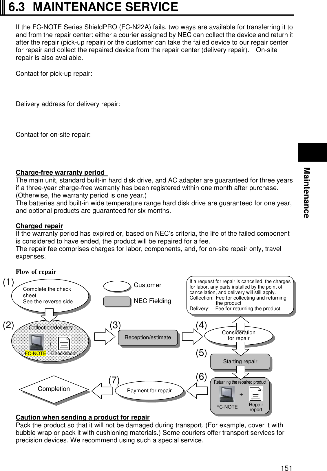
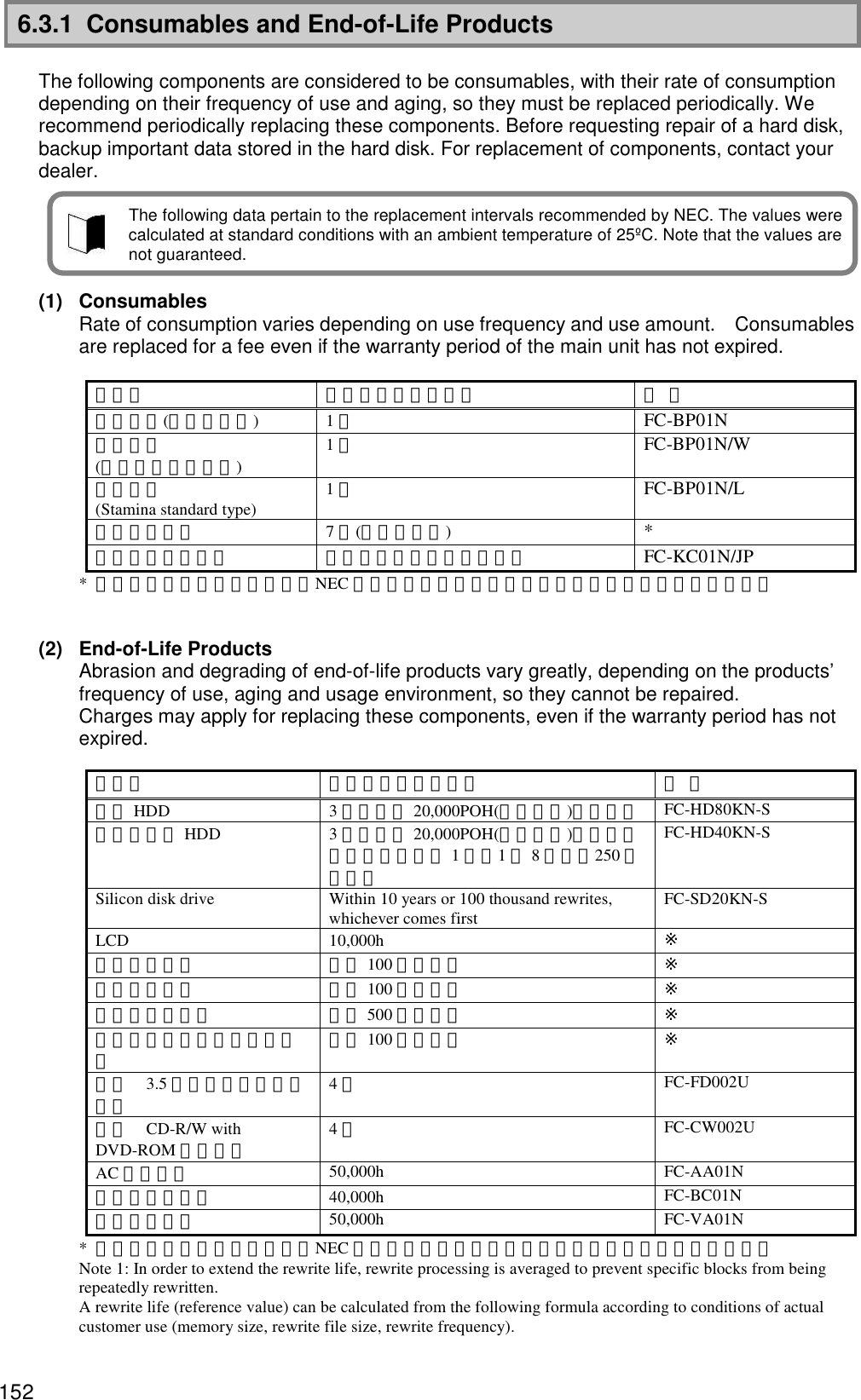
![153 Maintenance · Silicon disk size : Cp = 8,000,000 [KB] · Write target area size : Da [Byte] = 8,000,000 [KB] · Write target block : DaB [block] = 16,000 [blocks] · Rewrite data size : X [KB] · Rewrite frequency per hour : Z [no. of times/hour] · Operating time per day : H [hours] · Operating days per year : D [days] · Number of blocks used for 1 rewrite of data size X: A=ROUNDUP(X / 512 [KB]) 4 = [No. where decimal point of X / 512 [KB] is rounded up] 4 * Rewrite life [Years] (reference value) = (100,000 times DaB) / (Z A H D). 6.3.2 Service Menu The following FC98-NX Series Support Pack maintenance pack is offered. Three service types can be selected. 1) On-site repair service A service engineer visits the installation site and repairs the system when a problem occurs. 2) Pick-up repair service A company assigned by NEC picks up the device and delivers the repaired one. 3) Delivery repair service The customer sends the device with a failure to our repair center for repair.](https://usermanual.wiki/NEC/FC-N22A/User-Guide-987184-Page-153.png)
![154 6.4 FAILURE OR ABNORMALITY 6.4.1 If a failure is suspected If you suspect that the device has a failure, follow these procedures: 1. Make sure that the AC adapter or car adapter, power cable, and cables connecting other devices are securely connected. 2. See “Chapter 8 Troubleshooting”. When a corresponding symptom is shown, take appropriate measures according to the instructions. 3. Make sure that software required for operating the main unit is correctly installed. 4. Use a commercially available virus detection program to check the product. If a failure still persists after the above measures have been taken, do not try to operate the device, but contact your dealer or nearest maintenance service company instead. Before requesting service, record the lamp conditions of the main unit and alarm display on the screen, which may be helpful for deciding causes. When requesting repair of a product still under warranty, also submit the warranty card. [Information to be provided when making inquiries] When inquiring about the factory computer or a peripheral device which failed, information such as the usage environment and specific symptoms of the failure will be required. Before inquiring with the support center, enter the factory computer type, failure details, and other information into the problem check sheet at the end of this document. Operating environment 1. Hardware environment Main unit model name, serial number (warranty number), and available hard disk space; as well as types, model names, and product names (manufacturer names) of your peripheral devices (external monitor, printer, expansion hard disk drive, card devices, etc.) 2. Software environment OS and its version and manufacturer, application running when a failure occurs; specific symptoms, such as how the device was operating, display, frequency of failures; any other matters you noticed. The FC User Lounge accepts customers’ inquiries. This is a service providing the latest technical information (general information), Q&As, and information for checking third parties’ products. Registration (free of charge) is required to use this service. 6.4.2 Before Requesting Repair Prepare the following when requesting repair. 1. Warranty card 2. Notes of message on the display device 3. Failure information (Problem check sheet at the end of this document) * NEC shall not be held responsible for the data stored in the hard disk. Make a backup copy of data stored in the hard disk. * Once the device has been repaired, any information set by the customer (such as revisions in the BIOS setup menu and registered fingerprint information and other security settings) will be lost. Such information must be re-set.](https://usermanual.wiki/NEC/FC-N22A/User-Guide-987184-Page-154.png)
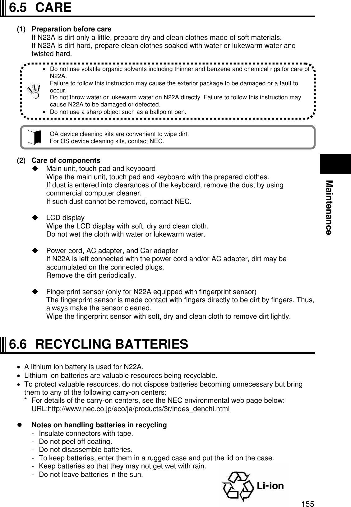

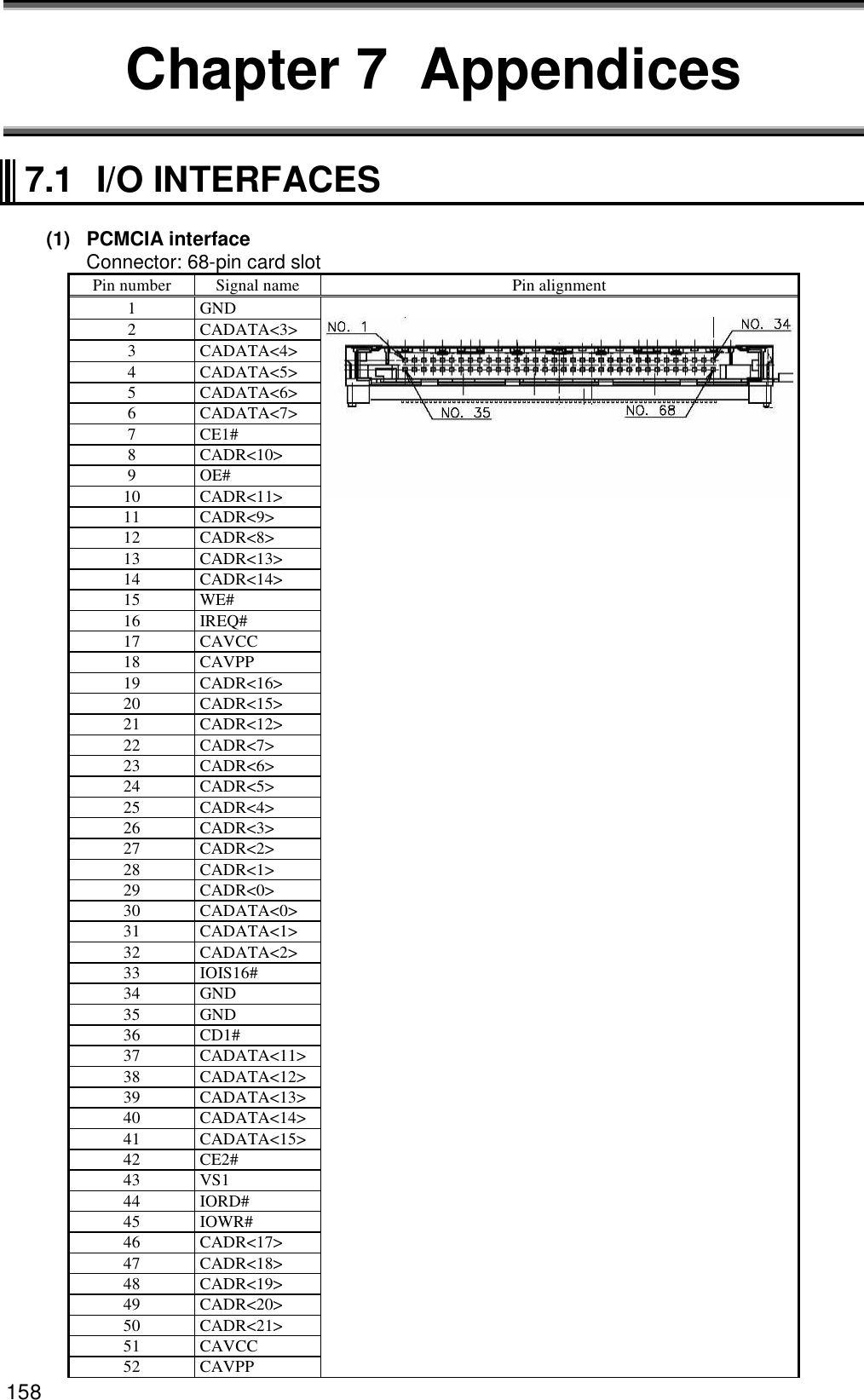
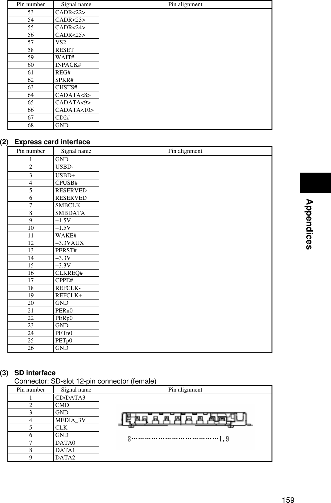
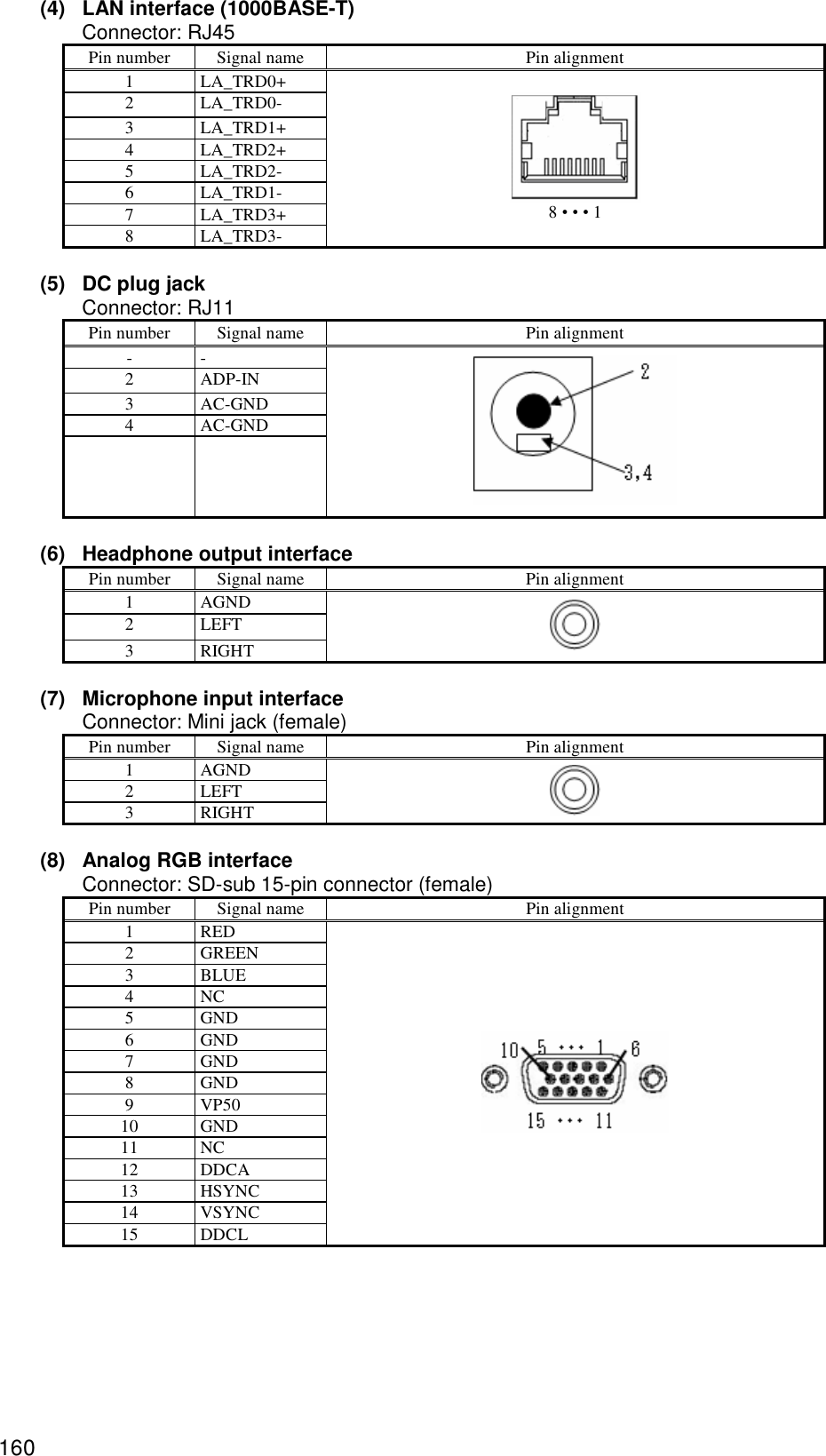
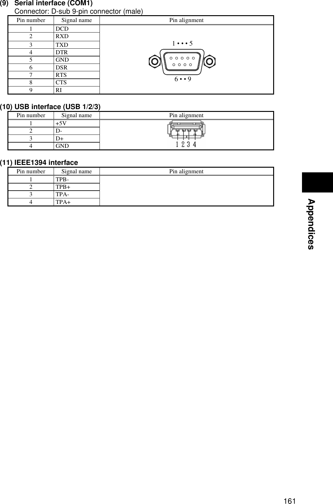
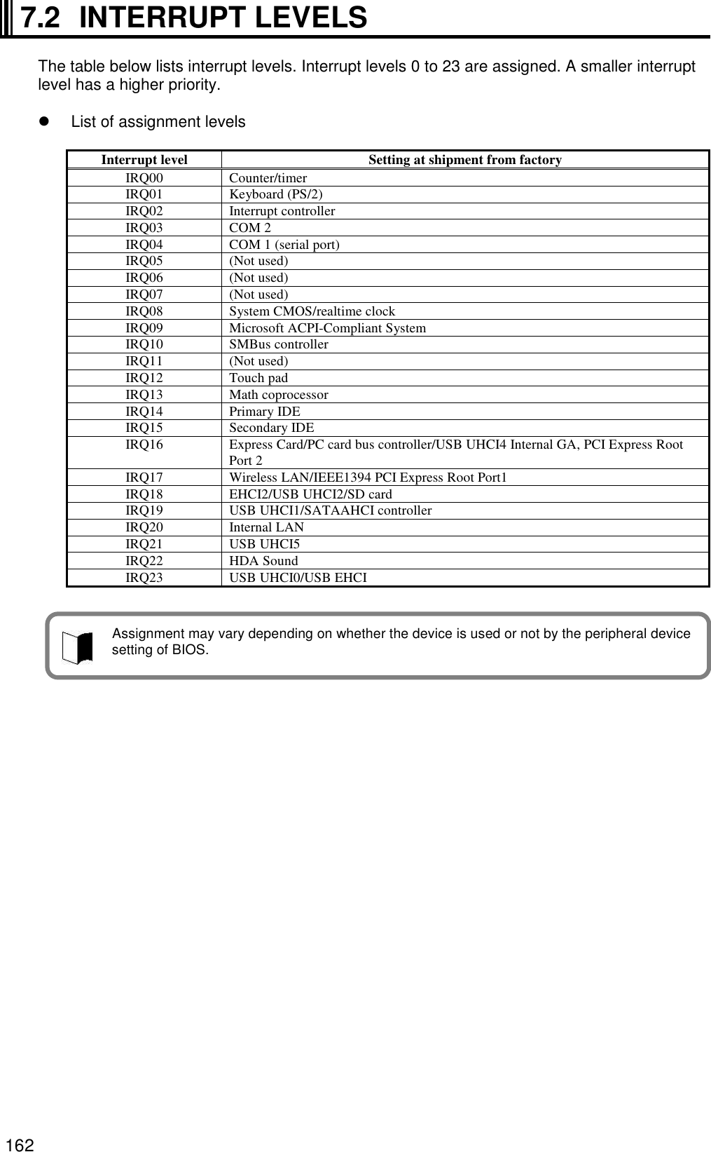
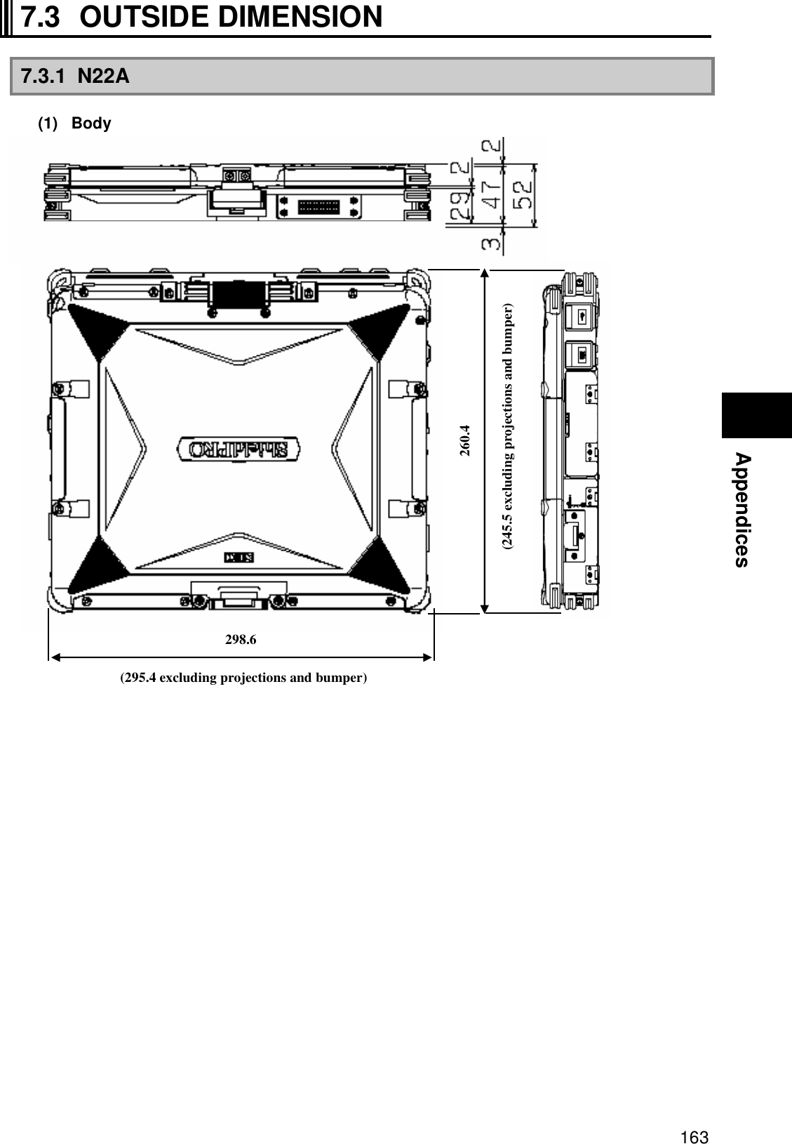
![164 * Excluding projections (including rubber feet and protect rubbers at 4 corners) [Rotation of LCD display panel] 389.8 [Body with LCD display panel made upright (node type)] 283.6 Unit: mm](https://usermanual.wiki/NEC/FC-N22A/User-Guide-987184-Page-164.png)
![165 Appendices * Excluding projections (including rubber feet and protect rubbers at 4 corners) 7.3.2 Spare Battery (FC-BP01N, FC-BP01N/W, FC-BP01N/L) 483.4 20.5 145.1 100.69 Unit: mm Unit: mm Weight: about 0.33 kg(FC-BP01N) about 0.33 kg(FC-BP01N/W) about 0.21 kg(FC-BP01N/L) [Body with LCD display panel taken down]](https://usermanual.wiki/NEC/FC-N22A/User-Guide-987184-Page-165.png)
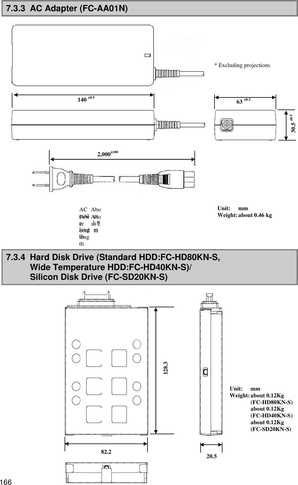
![167 Appendices Problem check sheet When making an inquiry, you will be asked the configuration of the product in use and specific conditions of the problem. Before inquiring, complete each item of this sheet, which will lead to a prompt and appropriate response. We recommend using this sheet. Problem Check Sheet 1 Configuration of device Hardware Main unit Model number (shown on the warranty) FC-N22A/ Serial number (warranty number) S Memory capacity MB (MegaByte) Hard disk capacity GB (GigaByte) Available hard disk space GB (GigaByte) MB (MegaByte) To check the hard disk capacity and available space, click [My computer] and right-click the hard disk icon followed by [Properties] in the menu shown. The capacity and space will be shown. Peripheral devices Product name and model name (manufacture name) Expansion memory Display Printer Expanded hard disk drive Network board PC card Other peripheral device(s)](https://usermanual.wiki/NEC/FC-N22A/User-Guide-987184-Page-167.png)