User Manual

NEC Factory Computer
FC-NOTE Series
N22A
User’s Manual
2
Introduction
Thank you for your purchase of the N22A Factory Computer.
This is a robust notebook PC providing in a highly mobile frame robust characteristics demanded for
use in harsh fields.
This computer is useful as an information terminal in various fields, such as field maintenance and
construction sites.
This manual explains how to use this product and how to expand options.
Note that illustrations and images in this document may differ slightly from actual products.
Trademarks
Microsoft and Windows are registered trademarks or trademarks of Microsoft Corporation in the United States and
other countries.
Windows® XP is an abbreviation for Microsoft® Windows® XP Home Edition Operating System and Microsoft®
Windows® XP Professional Operating System.
Intel, Intel Core, and Intel SpeedStep are registered trademarks or trademarks of Intel Corporation or their affiliate
companies in the UnitedStates and other countries.
Standby Rescue and Standby Rescue Lite are trademarks of NetJapan.
Sonic RecordNow! and Sonic DLA are registered trademarks of Sonic Solutions.
SD, miniSD, and microSD are trademarks of the SD Card Association.
Memory Stick and Memory Stick PRO are registered trademarks or trademarks of Sony Corporation.
Bluetooth® is a trademark of its owner. NEC Corporation uses it under a licensing agreement.
ShieldPRO is a trademark of NEC Corporation in Japan.
DeviceProtector is a trademark of NEC Personal Products, Ltd.
Adobe, Adobe logo, and Acrobat are trademarks of Adobe Systems Incorporated in the United States and other
countries.
All other product, brand, or trade names used in this publication are the trademarks or registered trademarks of their
respective trademark owners.
© NEC Corporation 2008
No part of this manual may be reproduced in any form without the prior written permission of NEC Corporation.

3
About this document
This is a guide for correctly setting up and using the FC-N22.
This document comes in the following structure.
Manual structure
Be sure to read the following before using the computer.
Read me first For safe use
Describes information required to safely
use this computer
Nomenclature and functions of parts CHAPTER 1
1.3.1 Names and Features of Sections of
FC-N22A
Use environment conditions CHAPTER 1
1.1.3 Environmental Specification (Main Unit)
Turning on/off CHAPTER 2
2.2 TURNING ON/OFF POWER
Battery installation CHAPTER 1
1.5 INSTALLING BATTERY
Read according to your model.
Battery types CHAPTER 2
2.8 BATTERY
Disk types CHAPTER 2
2.13 HARD DISK DRIVE/SILICON DISK
DRIVE
Keyboard types CHAPTER 2
2.4 KEYBOARD
Wireless LAN model
Bluetooth model
CHAPTER 2
CHAPTER 2
2.12.4
2.12.5
Wireless LAN (applied to N22A of
wireless LAN installation model only)
Bluetooth (applied to N22A of
Bluetooth installation model only)
Fingerprint sensor model CHAPTER 2
2.11 FINGERPRINT SENSOR (APPLIED TO
FS-N22 OF FINGERPRINT SENSOR
CHAPTER 5
5.2.4 Fingerprint authentication utility (only
models with this feature)
CHAPTER 3
3.4 FINGERPRINT AUTHENTICATION
PASSWORD (APPLIED TO N22A
OF FINGERPRINT SENSOR
INSTALLATION MODEL ONLY)
Windows® XP model CHAPTER 5
5.1 Windows XP PRE-INSTALLED
MODEL
Read the following, as required
Changing the BIOS setting CHAPTER 4
SETTING BIOS
Using the accompanying applications
CHAPTER 5
5.2 INSTALLING ATTACHED
APPLICATIONS
CHAPTER 6
6.4 FAILURE OR ABNORMALITY
In case of difficulty
CHAPTER 6
6.1 TROUBLESHOOTING
Interrupt level CHAPTER 7
7.2 INTERRUPT LEVELS
Profile of this product CHAPTER 7
7.3 OUTSIDE DIMENSION
Provided in the accompanying manual
Provided in the electronic manual
4
For safe use
The following includes information necessary for proper and safe operation of the product.
Before using this product, read this manual carefully and keep cautions.
Keep this manual at hand to see whenever it is necessary.
The following symbols are used in this manual so that the user can avoid personal injury or damage
to the properties.
The following shows the extent of effects if the instruction in this document is
followed.
WARNING
Indicates there is a risk of death or serious personal injury.
CAUTION Indicates there is a risk of personal injury or property damage.
The following labels describe how to prevent injury and/or damage to property.
Prohibited Indicates prohibited action.
Attention to fire Indicates there is a risk of fume and/or a fire.
Attention to electric
shock Indicates there is a risk of electric shock.
Attention to personal
injury Indicates there is a risk of personal injury.
Attention to laser
beam Indicates there is a risk of loss of eyesight due to laser
beam.
Attention to high
temperature Indicates there is a risk of failure due to high
temperature.
Unplug the power
cord. Indicates an instruction to unplug the power cord.
Connect grounding
conductor. Indicates an instruction to connect the grounding
conductor.
5
Warning on using the main unit
WARNING
If this device emits smoke or an odd smell, or the main
unit is too hot to touch, turn the power off immediately
then remove the power cable plug from the AC outlet.
If the battery is connected, remove it after checking for
safety.
Using the computer in such conditions may cause a fire, burn, and/or
electric shock.
Do not touch the computer when it thunders.
Do not touch the computer, connected cables, and
peripheral devices, or install/remove such devices when
a thunderstorm is approaching.
Failure to follow this warning may cause an electric shock due to
thunderbolt.
Do not disassemble or modify the product.
Failure to follow this warning may cause an electric shock, fumes,
and/or fire.
Do not place the product in a fire, apply excess heat, or
short-circuit the terminal.
Failure to follow this warning may cause a heating, fire, and/or
explosion.
Place all bags and packing materials safely out of the
reach of small children, especially infants and toddlers.
These items may pose a choking or suffocation hazard.
Do not intentionally remove or damage any of the
warning labels.
The warning label is attached to components with possible danger in
your computer inform the user that a hazardous situation may arise when
using the product. If you find any labels totally/partially removed or
illegible due to damage, contact your service representative.
Warning on installation environment
WARNING
Observe the following precautions and use the product in
a place where environmental requirements are satisfied.
Failure to follow this warning may cause an electric
shock, fumes, and/or fire.
Do not install or use the product in a location with medical vapor emitting
in the air or medicals being contact with the product.
Do not use the product into which any liquid such as water, metals, and
other foreign substances are entered.
Always use or store each device under the installation environment
conditions. Nevertheless, do not use or store the device in an environment
where the temperature may fluctuate severely, such as where condensation
may result, even if such an environment is within the installation
environment conditions.
6
Warning on connection of power supply
WARNING
The AC adapter and AC cord are designed on the
assumption that it is connected to this product. The AC
adapter may be damaged if it is connected to a device
other than this product.
Do not connect the power cord to an outlet that has an
illegal number of connections.
The electric current exceeding the rated flow overheats the outlet, which
may cause a fire.
The AC cord shipped with this product can be
exclusively used for 120 VAC.
Do not connect this AC cord to an outlet of which rating exceeds 125
VAC. Failure to follow this instruction may cause a fire and/or electric
shock.
Insert the power plug into the outlet as far as it goes.
A halfway inserted power plug may cause a fire and/or an electric shock.
Do not pull the AC cord forcibly or put any heavy object
on it.
Breaking of wire may cause a fire and/or electric shock.
Do not touch with a wet hand
Touching the main unit or AC adapter with a wet hand while the power
cable is connected to a power outlet poses an electric shock hazard.
Do not use this product if dusts are accumulated on the
AC power cord plug.
With dust accumulated power plug, the electrical discharge (tracking)
occurs between plug pins and it may cause a fire.
Always hold the plugs of the AC cord in its removal. Do
not pull the cord.
Breaking of wire may cause a fire.
Do not use the AC cord with the plug blades being
unstable.
Poor connection may cause a fire.
Never use a broken power cable.
If the power cable becomes damaged, do not mend it with adhesive tape
or the like. The mended part may overheat, posing a fire or electric shock
hazard.
Use the specified AC adapter and power cable. Never
disassemble or modify the AC adapter.
Doing so may cause an electric shock, smoke or fire hazard.
Unplug the AC power cable when not using d
evice for an
extended period.
Degraded insulation may cause a short-circuit fire.
7
The drip-proof and dust-proof performance conforming
to IP54 are not applied to the AC adapter and AC cord.
Follow instructions described below when handling them to prevent
fume, fire, and/or electric shock to occur.
Do not drop or give impact to the battery.
Do not use the power cord with bent or bundled state.
Do not forcedly bend the root of the power cord.
Do not put any heavy object on the battery.
Do not wrap the battery with cloth or the like.
Do not use the battery in a place where the liquid such as water splashes.
Do not use any damaged battery.
Do not put the battery in a place near the thermal appliance.
Do not put the battery in a place where temperature changes drastically
(e.g., near the exhaust port of air conditioner and vicinity of entrance).
Do not use the battery in an area where inflammable gas and/or
combustible substance are placed.
Do not put the battery in a place where lamp black and/or steam is generated (e.g.,
galley and near the humidifier).
Do not use the battery in a place where salinity (e.g., sea breeze) or the corrosive gas
(e.g., hot spring) is generated.
Warning on car adapter connection
WARNING
Do not use the device while driving.
Doing so may cause a traffic accident.
The fuse should only be replaced with one of the
specified value.
Be sure to replace the fuse with one having the specified current capacity
(amperage). Use of a fuse having a current capacity exceeding the
specified value poses a fire hazard.
Do not use the car adapter in vehicles with an electrical
system other than 12 VDC or 24 VDC.
Otherwise a fire hazard may result. (If you are unsure, ask your
automobile dealer.)
Be sure to use the car adapter only for the specified
connection devices.
Use with other than the specified devices may pose an electrical shock or
fire hazard.
Never disassemble the car adapter.
Disassembling may pose a fire or electric shock hazard.
Do not place any object onto the connection cable or
wrap the cable with a cloth, to avoid a fire hazard.
When connecting the car adapter, also check the
vehicle’s owner’s manual for related information.
When supplying power from the cigar lighter socket, follow the cautions
stated in the vehicle’s owner’s manual, to avoid an electric shock or fire
hazard.
8
When installing or removing a peripheral device, be sure
remove the cigar lighter plug of the power cable from the
cigar lighter socket, to avoid electric shock.
Do not insert or remove the cigar lighter plug of the
power cable to or from the cigar lighter socket with a wet
hand, to avoid electric shock.
Securely connect the cigar lighter plug in the cigar l
ighter
socket of the vehicle.
A large current flows, so a bad connection poses a heat or fire hazard.
Be sure to grab the cigar lighter plug when removing the
power cable from the cigar lighter socket.
Pulling the cable may cause it to break or disconnect from the cigar
lighter plug, posing a fire hazard.
The drip-proof and dust-proof performance conforming
to IP54 are not applied to the car adapter. Follow
instructions described below when handling them to
prevent fume, fire, and/or electric shock to occur.
Do not drop or give impact to the battery.
Do not use the power cord with bent or bundled state.
Do not forcedly bend the root of the power cord.
Do not put any heavy object on the battery.
Do not wrap the battery with cloth or the like.
Do not use the battery in a place where the liquid such as water splashes.
Do not use any damaged battery.
Do not put the battery in a place near the thermal appliance.
Do not put the battery in a place where temperature changes drastically
(e.g., near the exhaust port of air conditioner and vicinity of entrance).
Do not use the battery in an area where inflammable gas and/or
combustible substance are placed.
Do not put the battery in a place where lamp black and/or steam is generated (e.g.,
galley and near the humidifier).
Do not use the battery in a place where salinity (e.g., sea breeze) or the corrosive gas
(e.g., hot spring) is generated.
Do not store the battery in a very hot or humid environment, such as on a dashboard or
where it may be exposed to direct sunlight.
9
Battery warnings
WARNING
The provided battery is designed to be used in this
product only. Do not use the battery for any other
device.
In addition, do not use any other battery than the provided battery for this
product.
Failure to follow this instruction may cause a fire and/or electric shock.
Always charge the battery as specified.
Charge the battery using the method specified in the manual.
Charging with another method may cause a fire and/or electric shock.
Never short-circuit the battery or expose it to heat or
flame.
An explosion or rupture may result. Doing so may cause a fire.
Do not disassemble or attempt to modify the battery.
Disassembling or modifying the battery may cause an explosion or liquid
leakage.
Use of a battery other than one specified by NEC, or a disassembled or
modified battery (except those repaired by NEC) are not subject to
guarantee for quality, performance, or safety.
Do not drop or throw the battery.
An impact may cause a rupture or leakage.
The battery charger is not resistant to dust, dropping,
vibration or shock. Follow instructions described below
when handling them to prevent fume, fire, and/or
electric shock to occur.
Do not drop or give impact to the battery.
Do not put any heavy object on the battery.
Do not wrap the battery with cloth or the like.
Do not use the battery in a place where the liquid such as water splashes.
Do not use any damaged battery.
Do not put the battery in a place near the thermal appliance.
Do not put the battery in a place where temperature changes drastically
(e.g., near the exhaust port of air conditioner and vicinity of entrance).
Do not use the battery in an area where inflammable gas and/or
combustible substance are placed.
Do not put the battery in a place where lamp black and/or steam is
generated (e.g., galley and near the humidifier).
Do not use the battery in a place where salinity (e.g., sea breeze) or the
corrosive gas (e.g., hot spring) is generated.
Do not store the battery in a very hot or humid environment, such as on a
dashboard or where it may be exposed to direct sunlight.
Do not apply to a device containing the battery vibration
or shock exceeding those of the installation environment
conditions.
Applying a strong vibration or shock to the battery may damage it,
posing a smoke or fire hazard.
10
Warning on use of wireless functions
WARNING
Any users with implantable cardiac pacemakers should
make this product apart from the pacemakers by 30 cm
or longer.
The pacemakers may be influenced by radio waves radiated from this
product.
In places where people may be close to one another
such as crowded trains, turn off the power of the N22A
or disable the wireless LAN feature.
This is because N22A may be close to people using medical devices
including cardiac pacemakers or rearing aids and have bad influences on
the medical devices.
Turn off this product or turn of all wireless
communication functions, such as wireless LAN or
Bluetooth, where medical institutions prohibit use of
this product.
Turn off this product or turn of all wireless
communication functions, such as wireless LAN or
Bluetooth, if a medical device is used nearby, even if use
of this product is permitted by a relevant medical
institution.
Failure to follow this instruction may have some influences on medical
equipment to cause accidents by malfunctions.
For details, contact the medical institutions where this product may be
used.
Turn off this product or turn off the wireless
communication functions, such as wireless LAN or
Bluetooth, when use of wireless or electronic devices in
aircraft is prohibited.
This product may have bad influences on electronic devices to cause
accidents.
For details, contact airline companies operating aircraft where this
product may be used.
If this product induces radio disturbance to other
devices during use of some wireless feature, disable the
wireless feature or stop using this product.
Failure to follow this instruction may have some influences on other
devices to cause accidents by malfunctions.
11
Other warnings
WARNING
Keep the battery away from the reach of children,
especially babies and toddlers.
Battery contains harmful mat
erials. Swallowing or licking them can be
very dangerous. If swallowed, contact a physician immediately.
Always use the specified battery with its polarities
correctly orientated.
Use of a battery cell other than one specified or which is incorrectly
oriented may cause it to rupture, causing injury or fire. Remove
depleted batteries from the device.
Do not charge or directly solder battery.
Charging or direct soldering battery cells may break the cells, causing
injury or fire.
Never short-circuit the battery or expose it to heat or
flame.
Short-circuiting the battery or exposing it to heat or flame may cause it
to heat or rupture, resulting in injury or fire. If the internal liquid is
touched or gets into the eye, thoroughly flush the affected area with
water and immediately contact a physician.
Correctly install peripheral devices following the
instructions described in the document, to prevent a
smoke or fire hazard.
12
Caution on use of the main unit
CAUTION
Do not use the main unit on lap for a long time
The bottom surface of this product may heat during operation, causing a
low-temperature burn.
A low-temperature burn is a burn symptomized by redness or spotting of
the skin when a specific portion has been in contact with a heating
object for a long time. Those who have sensitive skin should be
cautious.
Note that some part may become hot when this product
is operating, immediately after use, or the battery is
being charged.
Burns may result.
Do not scratch the liquid crystal display surface with a
pointed object.
Do not strongly press the liquid crystal display surface
or the outer frame.
Do not swallow or touch the liquid of the liquid crystal
display.
If the liquid crystal display breaks and the liquid inside enters the
mouth, immediately gargle and rinse the mouth. If the liquid contacts
the skin or an eye, immediately flush the skin or eye with flowing water
for at least 15 minutes and contact a physician.
Do not use the accompanying CD-ROM or DVD-ROM
disks in any device other than players supporting the
CD-ROM or DVD-ROM disks.
A loud volume may cause hearing loss or audio speaker or disk damage.
The hard disk drive is a precision device. Handle it
with caution and do not bump it.
13
Cautions on use of peripheral devices
CAUTION
Be careful when using the device with the tray of the
external CD/DVD drive ejected.
Bumping or hitting hand or leg to the CD/DVD drive tray may cause
injury or damage the device.
Never disassemble the external CD/DVD drive, to avoid
risk of failure, overheating, damage, or electric shock.
Do not directly view the laser light source of the external
CD/DVD drive or other device, to avoid eye pain or vision
damage.
Press the eject button of the external floppy disk with the
soft part of a finger.
Pressing the floppy disk eject button with the tip of the nail may cause
the floppy disk eject button to slip between the nail and finger tip,
causing injury.
Be careful when installing or removing the expansion
RAM board, so as not to bump, hit, or cut the finger, to
avoid injury.
Be careful when installing or removing a peripheral
device, not to bump, hit, or cut the finger, to avoid injury.
Caution on use of batteries
CAUTION
Be careful not to bump your finger when installing or
removing the battery, to avoid injury.
Do not place the battery in a very hot or humid
environment, or where it may be exposed to direct
sunlight.
Doing so may cause leakage and the performance or life of the battery
may be degraded.
If a battery leaks liquid, do not touch the liquid, to avoid
burning.
If you touch the liquid, thoroughly flush the affected area with water and
immediately contact a physician.
Do not combine different types of batteries for use, to
avoid battery leakage or rupture as well as burning or
other injury.
14
Other cautions
CAUTION
Use of wireless communication devices of this product
may badly affect hearing aids, such as by producing
noise.
Check for correct operation before using, to avoid hearing damage.
Be careful not to adjust the volume too loudly when using
headphones or headphone/microphone set.
Using such devices for a long time at a high volume may harm hearing.
After turning off the power of this product, wait for five
seconds or longer before the power is turned on again.
Turning on the power just after turn-off without a certain interval may
cause a malfunction or fault to occur.
Do not remove the memory cover when the power cable is
connected to an outlet or a battery is installed.
Doing so may cause electric shock.
When disconnecting the AC adapter/car adapter, first
unplug the power inlet side (cigar lighter socket side),
then unplug the PC side.
Removing the plugs in the reserve order may cause the AC adapter/car
adapter and/or this product to be damaged.
Avoid handling the product while eating, drinking and/or
smoking cigarettes.
A floppy disk contaminated with cigarette ash may cause data read/write
error or damage to the floppy disk drive.
Do not use any dirty floppy disk and/or CD-ROM.
Using a dirty floppy disk with sand, dust, and/or liquid (e.g., water) may
cause failure of the drive.
Be sure to power off this device and peripheral devices,
unplug the power cable from the outlet, and remove the
battery before maintenance.
Maintenance with power on poses an electric shock hazard.
Pay attention when relocating the product.
When relocating the product, close the LCD display panel and fix the
latches, pay attention not to give an excessive shock and/or vibration
defined in environmental specification.
If a shock and/or vibration given to the product exceeds the environmental
specification, internal hard disk drive and/or other components may be
damaged.
Notes on storage
Unplug the AC cord from the outlet if you do not use the product for a
long time.Do not leave any object made of rubber and vinyl contacting to
the product.Do not wrap the product with vinyl bag or leave rubber bands
or the like put on the product.Doing so may cause transformation of the
product surface.
15
Notes:
(1) No part of this manual may be reproduced in any form without the prior written permission of
NEC Corporation.
(2) The contents of this manual may be revised without prior notice.
(3) All efforts have been made to ensure the accuracy of all information in this manual. If you notice
any part unclear, incorrect, or omitted in this manual, contact your service representative.
(4) NEC assumes no liability arising from the use of this product, nor any liability for incidental or
consequential damages arising from the use of this manual regardless of Item (3).
(5) This product is not intended for use or control in the facilities or devices concerning human lives,
including medical devices, nuclear facilities and devices, aeronautics and space devices,
transportation facilities and devices; and facilities and devices requiring high reliability. NEC
assumes no liability for any accident resulting in personal injury, death, or property damage if
this product has been used in the above conditions. To use this product in facilities and devices
and/or control system, take sufficient considerations for safety such as redundant configuration,
fire delay measures, and malfunction prevention measures.
(6) This product (including software) is intended to be sold and used only in Japan. NEC does not
support maintenance service and technical support in any country outside Japan.
(7) The components used in this product may be changed to equivalent one to maintain long-term
supply.
(8) Use an operating system pre-installed in the internal hard disk drive and CD-ROMs provided
with the product can be used for this product only.
(9) It is a piracy to replicate a part or whole of software, or distributing it without permission of the
copyright owner.
Pay attention not to lose a license label of installed operating system (COA label) that is
attached to this product of pre-installed model.
The data you have saved in hard disk drive, floppy disk, and/or CD-ROM are excluded from the
warranty of this product. Be sure to make a backup copy of user data.
(10) It is recommended to install an anti-virus software and update the virus definition file in a
regular basis.
Precautions on Export
This product (including software) is a Japan-domestic specification, and does not conform to
the standards of the foreign country. NEC assumes no liability arising from the use of this
product in any other country than Japan. In addition, no maintenance service and technical
support for this product are not provided in any other country than Japan.
This product is a product controlled under the Foreign Exchange and Foreign Trade Control
Law of Japan and is subject to restriction in export (including carrying with you). Therefore, you
should take necessary procedures in accordance with the above Law to export this product.
Contact your service representative before exporting this product.
EMC Notice
Only cable less than 3 meter (except the LAN cable) need to be used with this product to satisfy
the electromagnetic compatibility (EMC directive 2004/108/EC).
Cautions on radio waves
This product is a VCCI Class B information technology equipment conforming to the
reference level of the Voluntary Control Council for Interference by Information Technology
Equipment (VCCI). If this product is used near a radio, TV and/or wireless device, this
product may cause poor receptions. Use this product according to descriptions in “Notes
on Use” and relevant sections.
The wireless LAN (5 GHz) can only be used indoors due to relevant radio laws. Use of
radio waves the in 5 GHz (W56) frequency band outdoors is not prohibited by the radio
law.

16
This product is a radio equipment that satisfies “Station of the small electric power data
communications system” defined in Article 6, Paragraph 4 of the radio law ministerial
ordinance in Japan. It also satisfies “Local telecommunication terminal equipment using
the radio wave” defined in Article 36 of ordinance for terminal equipment in Japan.
Disassembling and/or modifying this product offense these laws. Never attempt to
disassemble or modify the product.
In addition, this product can be used only in Japan.
The radio wave output of this product is lower than the reference value defined in “Radio
Frequency-Exposure Protection Standard (RCR STD-38)” by Association of Radio
Industries and Businesses.
In the use frequency band of this product, RFID Equipment for Premises Radio Station
(license required), Specified Low Power Radio Station (license not required), and Radio
Equipment for Personal Use (license required) are operated as well as industrial, scientific,
and medical equipment.
(1) Before using this product, make sure that the specific small-power wireless station or
amateur wireless station is not operating around you.
(2) If this product generates harmful radio interference to the local station for mobile object
identification, immediately change frequency bandwidth or stop emitting radio wave.
Then, consult with your service representative about measures to avoid radio
interference (e.g., installing a partition).
(3) If this product generates harmful radio interference to the specific small-power
wireless station or amateur wireless station, contact your service representative.
Stop emitting radio wave immediately if this product generates radio interference to the
local station for mobile object identification.
Federal Communications Commission (FCC) Notice
WARNING
Changes or modifications not expressly approved by the party
responsible for compliance could void the user’s authority to
operate the equipment.
NOTE: This equipment has been tested and found to comply with the limits for a Class B digital
device, pursuant to Part 15 ofthe FCC Rules.
These limits are designed to provide reasonable protection against harmful interference
in a residential installation.
This equipment generates, uses and can radiate radio frequency energy and, if not
installed and used in accordance withthe instructions, may cause harmful interference
to radio communications.
However, there is no guarantee that interference will not occur in a particular
installation.
If this equipment does cause harmful interference to radio or television reception, which can
be determined by turning the equipment off and on, the user is encouraged to try to correct
the interference by one or more of the following measures:
Reorient or relocate the receiving antenna.
Increase the separation between the equipment and receiver.
Connect the equipment into an outlet on a circuit different from that to which the receiver is
connected.
Consult the dealer or an experienced radio/TV technician for help.
Properly shielded a grounded cables and connectors must be used for connection to host
computer and / or peripherals in order to meet FCC emission limits.
USA:Federal Communications Commission(FCC)
This device complies with Part 15 of the FCC Rules. Operation of the device is subject to the
following two conditions:
This device may not cause harmful interference.

17
This device must accept any interference that may cause undesired operation.
NOTE:The radiated output power of the wireless network device is far below the FCC radio
frequency exposure limits.
Nevertheless, wireless network device should be used in such a manner that potential
for human contact during normal operation is minimized.
In according with 47 CFR Part 15.407(e) U-NII devices operating in 5.15 - 5.25 GHz frequency
bands are restricted to indoor operations only.
This transmitter must not be co-located or operated in conjunction with any other anernna
transmitter.
Europe Frequency Bands
2.400 – 2.4835 GHz (Europe ETSI)
5.15 – 5.35 GHz and 5.47 – 5.725 GHz (Europe ETSI)
Low band 5.25 – 5.35 GHz is for indoor use only
5.47 – 5.725 GHz is current not allowed in Czech Republic and France.
R&TTE Directive
We, the manufacturer (NEC Corporation) hereby declare that this equipment (N22A), model
XXX is in compliance with the essential requirements and other relevant provisions of Directive
1999/5/EC.
Notes on security in use of wireless LAN products
The wireless LAN is advantageous to allow LAN connection freely within the radio wave range
because data is transmitted among wireless access points including computers through radio
waves instead of using LAN cables.
On the other hand, since radio waves reach any locations over obstacles (including walls)
within a certain range, the following problems may occur without security.
Stealing communication data
Malicious outsiders may intentionally intercept radio waves to steal communication
data as follows:
Personal information including IDs, passwords and credit card numbers
Mail contents
Invading into network illegally
Malicious outsiders may access to personal and corporate networks without notice to
take the following actions:
Acquiring private and confidential information (information leak)
Make communication as a specific person to spread illegal information (spoofing)
Rewrites intercepted communication data to be transmitted (falsification)
Spread computer virus to destroy data and/or systems (destruction)
Security-related setting to address the above issues is provided for wireless LAN cards and
wireless access points of this product. It is recommended to use the product with the security
setting at your discretion and under your own responsibility after thoroughly understanding the
possible outcome if no security setting is made.
18
Information in use of wireless LAN/Bluetooth products
This product and your Health
This product, like other radio devices, emits radio frequency electromagnetic energy. The level
of energy emitted by this product however is far much less than the electromagnetic energy
emitted by wireless devices like for example mobile phones.
Because this product operates within the guidelines found in radio frequency safety standards
and recommendations, we believe this product is safe for use by consumers. These
standards and recommendations reflect the consensus of the scientific community and result
from deliberations of panels and committees of scientists who continually review and interpret
the extensive research literature.
In some situations or environments, the use of this product may be restricted by the proprietor
of the building or responsible representatives of the organization. These situations may for
example include:
Using this product on board of airplanes, or
In any other environment where the risk of interference to other devices or services is perceived
or identified as harmful.
If you are uncertain of the policy that applies on the use of wireless devices in a specific
organization or environment (e.g. airports), you are encouraged to ask for authorization to use
this product prior to turning on the product.
Regulatory Information
We are not responsible for any radio or television interference caused by unauthorized
modification of this product.
The correction of interference caused by such unauthorized modification will be the
responsibility of the user. We and its authorized resellers or distributors are not liable for
damage or violation of government regulations that may arise from failing to comply with these
guidelines.
Transfer to Third Party
The following must be observed when you transfer (or sell) the product or software provided
with the product to a third party. In addition, be sure to include this User’s Guide when you
transfer (or sell) the product to a third party.
About data on the hard disk drive
Be sure to take appropriate measures not to leak important data (e.g., customers’
information or companies’ management information) on the hard disk drive to be
transferred to any third parties.
Data seems to be erased when you empty “Recycle Bin” or execute the “format” command
of the operating system. However, the actual data remains written on the hard disk drive.
Data not erased completely may be restored by special software and used for unexpected
purposes.
It is strongly recommended that the Hard Disk Erase feature in BIOS SETUP menu or the
software or service (both available at stores) for data erasure should be used in order to
avoid the trouble explained above. NEC shall not assume any liability for such data leakage
caused by your failure to take necessary measures.
Provided software
To transfer or sell any software that comes with the product to a third party, the following
requirements must be satisfied:
All provided software must be transferred and no backup copies must be retained.
Transfer requirements listed in “Software License Agreement” that comes with each
software must be satisfied.
Software that are not approved for transfer must be uninstalled before transferring the
product.
19
Disposal of Consumed Parts and Equipment
Consult with your service representative for disposal of the product and optional devices.
Recycling Batteries
A lithium ion battery is used for this product.
Lithium ion batteries are valuable resources being recyclable.
To protect valuable resources, do not dispose batteries becoming unnecessary, but bring
them to any of the following carry-on centers.
* For details of the carry-on centers, see the NEC environmental web page below:
URL:http://www.nec.co.jp/eco/ja/products/3r/indes_denchi.html (As of May 2008)
Notes on handling batteries in recycling
Insulate connectors with tape.
Do not peel off coating.
Do not disassemble batteries.
To keep batteries, enter them in a rugged case and put the lid on the case.
Keep batteries so that they may not get wet with rain.
Do not leave batteries in the sun.
Notes on Use of N22A in FA Environment
Note the following particularly to allow N22A to be used in FA environments.
(1) Dust-proof and drip-proof and performance
N22A is designed to have high seal performance to prevent liquid and dust from being
entered into it from any directions.
N22A can be used outdoor if it rains and handled with wet and/or dirt hands.
With optional dust-proof and drop-proof cables (FC-SC01N/FC-SC02N/FC-SC03N),
N22A has drip-proof and dust-proof performance conforming to IP54 if it connects with
one or more external devices.
To make dust-proof performance effective, the connector, HDD, battery and memory
covers must be closed appropriately.
N22A should be provided with maintenance including water wiping and drying so that
N22A does not be left wet for a long period.
In addition, place and operate N22A with its bottom facing downward.
20
(2) Operating temperature range
N22A of wide temperature type can operate in the temperature range between -20ºC
and 50ºC while N22A of other types operate in temperature range between 5ºC and
45ºC.
To allow N22A to be used in the wide temperature range (-20 to 50ºC), the main unit,
HDD and battery should all be available in the wide temperature range.
In environment at a high temperature, the main unit may be heated. If so, wear gloves
not to make your hands contact with the unit directly.
To suppress heat generation, the performance of N22A may be restricted automatically.
In environment at a low temperature, the battery driving time is shortened.
In addition, the LCD display can make responses slower.
(3) Shock resistance
The chassis of N22A is made of magnesium die-casting alloy and equipped with a hard
disk drive subjected to shock resistance.
N22A is designed to have the strength of enduring the test in which it is dropped from a
height of 90 cm to plywood or concrete floor.
(4) Vibration resistance
The vibration resistance of N22A does not assure that it has sufficient strength against
resonance generated when added vibration is close to the natural frequency of N22A.
(5) Continuous operation of N22A for long period
If N22A is operated continuously for a long period, deterioration of life parts in N22A may
be accelerated. Therefore, NEC may charge the repair of N22A defected due to
continuous operation for a long period within the warranty period.
N22A in the tablet mode or the battery charging state should be used in ambient temperature
range 5 to 40ºC.
The AC adapter can be used where the ambient temperature is -20ºC to 50ºC.
Note that, if a hard disk drive (wide temperature range type: FC-HD40KN/S) and replacement
battery (wide temperature range type: FC-BP01N/W) are mounted in models other than wide
temperature range types, they cannot be used in a wide temperature range (-20ºC to 50ºC).
IP54
Dust-proof performance:
Protection class IP5x means that a device of the class cannot completely avoid entry of dust
but the dust do not interrupt the defined operations and safety of the device.
Drip-proof performance:
Protection class Ipx4 means that a device of the class is not affected by spray from every
angle (by a spray nozzle).
Use optional dust-proof and drip-proof cables (FC-SC01N/FC-SC02N/FC-SC03N) as
connection cables for the LAN, serial, or USB ports. For the power connector or PC slot cover,
use an optional dust-proof, drip-proof cover (FC-SC04N/FC-SC05N).
For other connection ports, securely close the connector covers during operation.
When relocating the product, close the LCD panel display and fix the latches.
This product has excellent shock-proof characteristics, but prevention of damage or failure is not
guaranteed.
N22A damaged by shocks may reduce its dust-proof and drop-proof performance as well as the
shock resistance. Accordingly, it is recommend to repair damaged N22A.
21
When using the LCD in the high brightness condition for a long time, it is recommended
to set the backlight to automatically turn off when a specified time has elapsed, via the
power management control of the OS (Windows). The backlight will degrade earlier in
a high-temperature environment. Also, use of a silicon disk is recommended.
When using a hard disk drive, periodically shut down the computer so that the HDD will
stop operating, to reduce degradation due to continuous operation.
Operation sample:
The power management may be set by OS (Windows) to halt the HDD automatically if
accessing to hard disks does not occur for a certain period:
Period set at shipment : 30 minutes (when N22A is connected to AC power)
Recommended period : 3 minutes (when N22A is connected to AC power)
The number of writes to a silicon disk is restricted. See “Consumables and End-of-Life
Products” in “CHAPTER 6 MAINTENANCE” for details.
For health
The following explains recommendations to be noted for your health when using this product.
It is said that long-term work with a computer can lead to accumulated fatigue, causing eye fatigue,
a heavy-head feeling, blurred vision, or neck numbness or pain, from the shoulders to the fingers.
Maintain a good posture and properly adjust the devices when using a computer. Rest appropriately,
about 10 to 15 minutes every hour, and exercise to prevent further fatigue.
Preferable working posture
It is recommended to operate a computer, while feeling relaxed without excessive intension.
Seated with your back against the seat back so that your back is supported
Placing the keyboard horizontally with the floor so that both hands are at the same height
Setting the screen lower than your eyes so that the visual line is slightly low.
Adjustment of devices
If the device is adjustable, adjust it as required to be optimized for the user.
Adjustment of screen brightness
The optimum brightness of the screen differs depending on the individuals or ambient
brightness. Adjust the screen brightness according to the conditions, whenever required.
Clean the devices
Dirty screens reduce visibility. Periodically clean the screen.
Information on the FC98-NX and
FC-NOTE Series
Information on the FC98-NX Series/FC-NOTE Series is available at the following Web page.
This page provides information on these computers, such as what’s new, product information,
Features of FC98-NX Series/FC-NOTE Series, cautions for installation, shipping termination, and
planned shipping termination.
22
URL:http://www.nec.co.jp/fc
Symbols in the Text
This User’s Guide uses the following symbols to distinguish each element of sentences.
If the description is ignored to handle the product, the product may be defected, some
software used in the product may be broken, and/or the data created by the user may
be broken.
If the description is ignored to handle the product, the product may be defected and/or
some software used in the product may not operate normally.
This User’s Guide also uses the following symbols.
Supplement of the text
Reference page
Typographical Conventions concerning
Keyboard Operation
Keyboard keys are represented in bold-faced letters.
Example: Press Enter to exit.
When several keys are combined with plus sign (+), press and hold the first key, press another key,
and then release all the keys. Keys may be indicated by an illustration.
Titles, commands, setup items, or buttons displayed on screen are shown in bold-face characters.
Values or options that can be selected for setup items are shown in italics.
An example is shown below.
Example: Select Power management, set to Enabled, and then click the OK button.
23
Contents
INTRODUCTION ................................................................................................................. 2
ABOUT THIS DOCUMENT ................................................................................................. 3
FOR SAFE USE .................................................................................................................. 4
FOR HEALTH.................................................................................................................... 21
INFORMATION ON THE FC98-NX AND FC-NOTE SERIES ........................................... 21
SYMBOLS IN THE TEXT .................................................................................................. 22
TYPOGRAPHICAL CONVENTIONS CONCERNING KEYBOARD OPERATION ........... 22
CONTENTS....................................................................................................................... 23
CHAPTER 1 SYSTEM OVERVIEW AND PREPARATION............................................... 27
1.1 SPECIFICATIONS.............................................................................................................. 27
1.1.1 Hardware Specification...................................................................................................27
1.1.2 Selection Menu Table.....................................................................................................30
1.1.3 Environmental Specification (Main Unit).......................................................................31
1.2 CHECKING ACCESSORIES .............................................................................................32
1.3 EXTERIOR VIEW ..............................................................................................................33
1.3.1 Names and Features of Sections of N22A ......................................................................34
1.4 INSTALLATION GUIDE...................................................................................................38
1.5 INSTALLING BATTERY ..................................................................................................40
1.6 INSTALLING AC ADAPTER............................................................................................ 41
CHAPTER 2 USES OF N22A............................................................................................ 43
2.1 OPENING/CLOSING LCD DISPLAY PANEL AND SETTING TABLET MODE......... 43
2.1.1 Opening Panel.................................................................................................................43
2.1.2 Closing Panel..................................................................................................................43
2.1.3 Turning Screen (to be in tablet mode) ............................................................................44
2.1.4 Returning Screen to its Original Position .......................................................................44
2.2 TURNING ON/OFF POWER ............................................................................................. 45
2.2.1 Turning on Power ...........................................................................................................46
2.2.2 Turning off Power (shutdown)........................................................................................46
2.2.3 Power Saving Features....................................................................................................47
2.3 TABLET BUTTONS........................................................................................................... 51
2.4 KEYBOARD .......................................................................................................................52
2.4.1 English Keyboard ...........................................................................................................52
2.5 TOUCH PAD....................................................................................................................... 55
2.5.1 Setting Touch Pad...........................................................................................................56
2.6 TOUCH PANEL..................................................................................................................56
2.6.1 Setting Touch Panel........................................................................................................57
2.7 DISPLAY FEATURE.......................................................................................................... 58
2.7.1 Display Resolution..........................................................................................................58
2.7.2 Adjusting Screen Display ...............................................................................................58
2.7.3 Connecting External Monitor .........................................................................................59
2.8 BATTERY........................................................................................................................... 60
2.8.1 Notes on Batteries...........................................................................................................60
2.8.2 Battery Types..................................................................................................................61
2.8.3 Charging Battery.............................................................................................................61
2.8.4 Checking Remaining Battery Level................................................................................62
2.8.5 Replacing Battery ...........................................................................................................63
2.8.6 Actions Taken for Low Battery Charge Level................................................................65
2.8.7 Initializing Battery ..........................................................................................................66
2.9 PC CARD/EXPRESS CARD ..............................................................................................67
2.9.1 Supporting CardBus........................................................................................................67
2.9.2 Installing PC Card in N22A............................................................................................67
24
2.9.3 Removing PC Card from N22A ..................................................................................... 68
2.10 MEMORY CARD............................................................................................................... 69
2.10.1 Notes on Handling and Storage of SD Card................................................................... 69
2.10.2 Protecting Data............................................................................................................... 70
2.10.3 Installing or Removing SD Card in/from SD Card Slot ................................................. 70
2.11 FINGERPRINT SENSOR (APPLIED TO FS-N22 OF FINGERPRINT SENSOR
INSTALLATION MODEL ONLY) ................................................................................... 71
2.12 COMMUNICATION FEATURE ....................................................................................... 72
2.12.1 USB (USB 2.0)............................................................................................................... 72
2.12.2 IEEE 1394 devices ......................................................................................................... 73
2.12.3 LAN................................................................................................................................ 74
2.12.4 Wireless LAN (applied to N22A of wireless LAN installation model only).................. 76
2.12.5 Bluetooth Feature (only for models with this feature installed) ..................................... 82
2.12.6 Serial Port....................................................................................................................... 82
2.13 HARD DISK DRIVE/SILICON DISK DRIVE.................................................................. 83
2.13.1 Installing/Removing HDD/Silicon Disks ....................................................................... 84
CHAPTER 3 SECURITY....................................................................................................85
3.1
SETTING PASSWORD ON BIOS SETUP UTILITY
........................................................... 85
3.2 LOGIN PASSWORD.......................................................................................................... 86
3.3 SECURITY CHIP ............................................................................................................... 86
3.4
FINGERPRINT AUTHENTICATION PASSWORD (APPLIED TO N22A OF FINGERPRINT
SENSOR INSTALLATION MODEL ONLY)
....................................................................... 87
3.5 ANTITHEFT LOCK ........................................................................................................... 87
CHAPTER 4 SETTING BIOS.............................................................................................88
4.1 BIOS SETUP UTILITY...................................................................................................... 88
4.1.1 Settings on BIOS SETUP Utility.................................................................................... 88
4.1.2 Running/exiting BIOS SETUP Utility............................................................................ 89
4.1.3 Loading the BIOS SETUP Defaults ............................................................................... 90
4.2 LIST OF BIOS SETUP MENUS ........................................................................................ 91
4.3 MAIN MENU...................................................................................................................... 95
4.4 ADVANCED MENU CONFIGURATION ........................................................................ 96
4.4.1 Advanced Menu Configuration ...................................................................................... 96
4.4.2 PCI Configuration Submenu .......................................................................................... 98
4.4.3 I/O Device Configuration Submenu............................................................................... 98
4.4.4 Tablet Button Submenu................................................................................................ 101
4.5 SECURITY MENU........................................................................................................... 102
4.5.1 Security......................................................................................................................... 102
4.5.2 I/O Lock Feature........................................................................................................... 107
4.5.3 Clearing BIOS Passwords ............................................................................................ 107
4.6 POWER MANAGEMENT CONFIGURATION ............................................................. 108
4.6.1 Power Management Configuration............................................................................... 108
4.7 SYSTEM MENU .............................................................................................................. 110
4.8 BOOT MENU ................................................................................................................... 111
4.8.1 Boot Order Configuration............................................................................................. 111
CHAPTER 5 INSTALLING OS AND APPLICATIONS....................................................112
5.1 WINDOWS XP PRE-INSTALLED MODEL .................................................................. 112
5.1.1 Configuration of Windows XP Pre-installed Model..................................................... 112
5.1.2 “Microsoft Windows XP Service Pack 2”.................................................................... 114
5.2 INSTALLING ATTACHED APPLICATIONS ............................................................... 115
5.2.1 Standby Rescue Lite..................................................................................................... 115
5.2.2 Software RAS Tool ...................................................................................................... 117
5.2.3 Adobe® Reader® 7.0..................................................................................................... 118
5.2.4 Fingerprint authentication utility (only models with this feature)................................ 119
5.2.5 Infineon Security Platform ........................................................................................... 121
5.2.6 FC Button Setting Tool ................................................................................................ 123
5.3 OTHER OSS AND APPLICATIONS .............................................................................. 124
25
CHAPTER 6 MAINTENANCE ......................................................................................... 126
6.1 TROUBLESHOOTING.....................................................................................................126
6.1.1 Flowchart ......................................................................................................................126
6.1.2 Actions Taken to Solve Trouble (Tips).........................................................................128
6.1.3 Troubleshooting Q&A..................................................................................................130
6.2 RE-SETUP OF Windows XP IN N22A OF PRE-INSTALLED MODEL........................141
6.2.1 Re-setup ........................................................................................................................141
6.2.2 Standard and Custom Re-setups ...................................................................................142
6.2.3 Repairing System..........................................................................................................143
6.2.4 Standard Re-setup.........................................................................................................144
6.2.5 Custom Re-setup...........................................................................................................148
6.3 MAINTENANCE SERVICE.............................................................................................151
6.3.1 Consumables and End-of-Life Products.......................................................................152
6.3.2 Service Menu................................................................................................................153
6.4 FAILURE OR ABNORMALITY......................................................................................154
6.4.1 If a failure is suspected .................................................................................................154
6.4.2 Before Requesting Repair.............................................................................................154
6.5 CARE................................................................................................................................. 155
6.6 RECYCLING BATTERIES..............................................................................................155
6.7 CARRIAGE AND STORAGE OF N22A .........................................................................156
6.8 DISPOSAL OF DEVICES ................................................................................................ 156
CHAPTER 7 APPENDICES ............................................................................................ 158
7.1 I/O INTERFACES.............................................................................................................158
7.2 INTERRUPT LEVELS...................................................................................................... 162
7.3 OUTSIDE DIMENSION................................................................................................... 163
7.3.1 N22A.............................................................................................................................163
7.3.2 Spare Battery (FC-BP01N, FC-BP01N/W, FC-BP01N/L)...........................................165
7.3.3 AC Adapter (FC-AA01N).............................................................................................166
7.3.4 Hard Disk Drive (Standard HDD:FC-HD80KN-S, Wide Temperature HDD:
FC-HD40KN-S)/ Silicon Disk Drive (FC-SD20KN-S)................................................166
INDEX......................................................................................................................................... 170
26
THIS PAGE INTENTIONALLY LEFT BLANK.
27
PREPARATION
Chapter 1 SYSTEM OVERVIEW
AND PREPARATION
1.1 SPECIFICATIONS
1.1.1 Hardware Specification
Item N22A(Note 1)
CPU (Note 2) Intel®CoreTM2Duo processor
Ultra low voltage version U7500
(Extended Intel SpeedStep® technology (Note 3) installed
[1.06 GHz])
Primary 32KB for instruction/32KB for data (built in CPU) Cache memory
Secondary 2.048KB (built in CPU)
System bus 533 MHz (memory bus: 533 MHz)
Chip set Mobile Intel 965GM Express chip set ICH8-M
Security chip (Note 4) Conforming to TPM V.1.2
Memory (Note 5) 4GB max. (Note 6)
2 SO-DIMM slots
DDR2-SDRAM (PC2-4200 (DDR2-533))
12.1-in. TFT color LCD display (XGA) with touch panel (Note 8) Display
element (Note 7)
Stuck pixels of LCD
(Note 9) 0.0003% or less
Graphic accelerator Built in mobile Intel 965GM Express chip set
(Dual display (Note 10), smoothing, and screen rotation features
available)
Video RAM 348MB max. (use of main memory)
Display feature
Resolution and display colors LCD: 1024×768 dots (16.77 million colors (Note 11))
External monitor: 1600×1200 dots max. (Note 12) (16.77 million
colors (Note 11))
Floppy disk drive [Option] FC-FD002U connectable (USB connection)
CD-ROM type drive [Option] FC-CW002U connectable (USB connection)
Fixed disk drive (Note 14)
[Selectable item] 80GB (Serial ATA specification) or 40GB
(wide temperature range and Ultra ATA specification)
Auxiliary storage (Note 13)
Silicon disk drive (Note14) [Selectable item] 20GB (Ultra ATA specification)
Keyboard (Note 15) [Selectable item]
Standard or backlight keyboard
English keyboard Key pitch: 17.55 mm
Key stroke: 2.4 mm(backlight keyboard : 2.0mm)
Pointing device Touch pad
Input device
Tablet button Desired functions can be assigned (up to 10)
USB (Note 16) 3 ports (including 1 connect/disconnect-proof enhanced port),
USB2.0 compatible
Serial 1 D-sub 9-pin connector of 115,200 bps max. (male)
Display Mini D-sub 15-pin connector (female) (for analog RGB monitor)
Built-in LAN 1 RJ45 (1000BASE-T / 100BASE-TX / 10BASE-T) LAN
connector
Network
Wireless LAN
[Selectable item] Conforming to IEEE802.11a/b/g (Note 17)
WEP [encryption key length: 64/128 bits (user setting key
length: 40/104 bits)],
WPA-PSK (TKIP/AES) and WPA2-PSK (AES) compatible
Interface (Note 13)
Sound feature Built-in PCM record/replay feature and monaural speaker
Microphone input (stereo, mini jack) and output common to
headphone/line (stereo, mini jack)

28
Item N22A(Note 1)
PC card slot (Notes 13 and 18) 1 Type I/II slot (Type III unavailable) conforming to PC Card
Standard and compatible with CardBus
Express card slot (Note 13 and 18) ExpressCard/34 · /54×1 slot
Triple memory slot (Note 13 and 18) 1slot
Security feature Security software normally attached (Note 19)
Finger print sensor
(Note 8) [Selectable item] Built-in type (line type)
Authentication by fingerprint at OS logon or release of screen
saver
Power management Automatic or arbitrary settings enabled (including CPU control
(Note 2), hard disk control, monitor power saving, suspend
(standby) feature and hibernation)
This machine Operating voltage: 16 V±5%
Battery (Notes 20 and 21) [Selectable item]
Standard type: driving period - 8 hours, charging time (in
power-on/off states) - about 3.5 hours/8 hours
and weight: about 0.4 kg
Wide temperature range type:
driving period - 6 hours, charging time (in
power-on/off states) - about 4 hours/8 hours
and weight: about 0.5 kg
Stamina standard type:
driving period - 12 hours, charging time (in
power-on/off states) - about
4 hours/8 hours and weight: about 0.5 kg
AC adapter 100 to 240 VAC ±10%, 50/60 Hz
[A specific cord is required if used in another country other than
Japan.]
Power supply
Car adapter [Option] FC-VA01N connectable ( DC12 to 24V , 7.5A )
Conforming standard Suitable to RoHS direct and conforming to VCCI Class B/FCC.
Designed based on EMC direct (EN55022 and EN61000-6-2)
(Note 22) and low voltage
direct (EN60950-1) (Note 22) standards. Power design based on
standard UL60950-1
Power consumption About 15 W (about 50 W max.)
Energy efficiency (Power saving
achievement rate) Target year: 2007 (Note 23), I division 0.0020 (A)
Outside dimension 290(W) × 255(D) × 47(H) mm (excluding projections and
bumper)
Weight About 2.5 kg (including standard battery)
Installed OS [Selectable item] Microsoft Windows XP Professional (Service
Pack 2) Japanese / English
1: See “Selection Menu Table” for type names and numbers.
2: N22A includes a control feature enabling the CPU to operate dynamically depending on use environments and
loads.
3: In any OS environment other than preinstalled OS environment, the expanded IntelSpeedStep feature may be
unavailable.
4: The security chip is unavailable to any OS other than preinstalled Windows XP Professional.
5: The capacity of a memory board can be selected out of 512MB, 1GB, 2GB, and 4GB on the selection menu.
6: Replacement of an expanded RAM board is enabled only on a single slot. The maximum memory capacity
can be installed if memory of 2GB or larger is selected.
If memory of less than 2GB is selected, the maximum memory capacity is “selected memory capacity” +
2GB.
7: The LCD display is manufactured based on extremely high-precise technology. However, dot drops (such as
negligible black points and red, blue or green points always illuminating) may appear on a part of the screen.
In addition, color and/or brightness irregularities may appear depending on view angles. These are caused by
characteristics of LCD displays and do not indicate any defects.
8: The touch panel is unavailable under USB locking.
9: The base dot drop rate is calculated in sub-pixels according to the standard of ISO13406-2.
See http://www.express.nec.co.jp/products/pc/lcddot.html for details.(As of May 2008)
10: The feature allows an external display for desktop screen to be different from the LCD display of N22A.
11: 16.77 million color display is accomplished by the dithering feature of graphic accelerator.
12: N22A has the resolution and the number of colors. However, N22A cannot realize them depending on the
resolution and refresh rate of the connected display. The LCD display on N22A and the external display
connected to N22A can display the same screen. However, if the enlarged display feature is not used, display
data may not extend to all over the external display.
29
13: Before a commercial product can be used for N22A, you should previously evaluate the product to confirm
that the product is valid.
14: Fixed and silicon disk drives should be installed exclusively with each other.
15: If Windows® XP Professional (Service Pack 2) English version preinstalled is selected, the product will be
shipped with an English keyboard.
16: Any software using peripherals connected to N22A must be fit to the USB interface.
17: N22A is equipped with a wireless LAN module obtaining Wi-Fi®, standard of the Wi-Fi Alliance. The
communication speed and distance may be affected by various factors including connected devices, radio
wave environment, surrounding obstacles, installation environment, use situation, used application software
and OS. IEEE802.11b/g (2.4GHz) is not compatible with IEEE802.11a (5GHz). The wireless LAN is suitable
to Super AG and Atheros XR (eXtended Range). The wireless LAN (5GHz) conforms to IEEE802.11a (W52,
W53 and W56). W52, W53 and W56 are notations defined by the Japan Electronics and Information
Technology Industries Association. 11a (W56), however, can be used outdoors.
The wireless LAN (5GHz) can only be used indoors due to relevant radio laws. To use N22A abroad, the
wireless LAN feature may conflict with related laws in the country. Accordingly, disable the wireless LAN
feature abroad.
18: PC card, SD card, and memory stick are options. Purchase commercial products.
19: Security software may not be used, depending on the OS for use.
See “5.2 INSTALLING ATTACHED APPLICATIONS” for the operating systems supported by software.
20: The battery driving and charging times may be different from the specified values depending on situations in
which the battery pack is used. The battery pack is a consumable.
21: The battery driving time is measured based on the JEITA battery operation time measurement method (Ver.
1.0). The time varies depending on operation environments, brightness of LCD display and system settings.
22: These standards are required for CE marking.
23: The energy consumption efficiency is obtained by dividing the power consumption measured based on the
measurement method defined by the Rationalization in Energy Use Law (target year: 2007) by the composite
theory performance defined by the Rationalization in Energy Use Law. Power saving achievement rates A,
AA and AAA means achievement rates equal to or larger than 100% and less than 200%, equal to or larger
than 200% and less than 500% and equal to or larger than 500%, respectively.

30
1.1.2 Selection Menu Table
Windows XP pre-installed model
Series title Selection menu
Base unit Keyboard OS Memory
capacity Disk drive and battery
Wireless LAN
and fingerprint
authentication
[B]
Standard
Japanese
keyboard
[X]
Windows XP
Professional
(Service Pack2)
Japanese ver.
preinstalled
[3]
512MB
(512MB × 1)
[S]
Standard HDD × 1
(SerialATA spec.,
80GB)
Standard battery
[B]
Wireless
LAN: No
Fingerprint
authentication:
No
Bluetooth:
Yes
[C]
Backlight
Japanese
keyboard
[Y]
Windows XP
Professional
(Service Pack2)
English ver.
preinstalled (Note 1)
[4]
1GB
(1GB × 1)
[T]
Standard HDD × 1
(SerialATA spec.,
80GB)
Stamina standard
battery
[F]
Wireless
LAN: No
Fingerprint
authentication:
Yes
Bluetooth: No
[G]
Standard
keyboard
[6]
2GB
(2GB × 1)
[W]
Wide temperature
range HDD × 1
(UltraATA spec.,
40GB)
Wide temperature
range battery
[S]
Wireless
LAN: Yes
Fingerprint
authentication:
No
Bluetooth:Yes
[H]
Backlight
keyboard
[F]
Silicon disk × 1
(UltraATA spec.,
20GB)
Stamina battery
[W]
Wireless
LAN: Yes
Fingerprint
authentication:
Yes
Bluetooth:
Yes
N22A
CPU
Windows® XP
Preinstalled model
Intel®CoreTM2Duo
processor
Ultra low voltage
version
U7500(1.06GHz)
Memory (3 slots)
PC card (1 slot)
SD card (1 slot)
Express card
× 1 slot
[H]
Silicon disk × 1
(UltraATA spec.,
20GB)
Wide temperature
range battery
[Z]
Wireless
LAN: No
Fingerprint
authentication:
No
Bluetooth: No
1: If Windows® XP Professional (Service Pack 2) English version preinstalled is selected, the product will be
shipped with an English keyboard.
* The part and generation numbers of N22A are directed on the nameplate and warranty at shipment. See the NEC
web site for details of the generation numbers.
Ex.: For order number FC-N22A/BX2SS, the notation on the nameplate and warranty is FC-N22A/BX2SS**
(**: generation number).
* N22A of Windows XP pre-installed model already has Microsoft Windows XP Professional Operating System
(Service Pack 2) installed. Note that deleting and down-grading of Service Pack is disabled.
First partition: 20GB (NTFS) (Software already installed at shipment occupies about 5GB in the first partition.)
Second partition: Remaining memory (NTFS)
Part name Model name
Part number
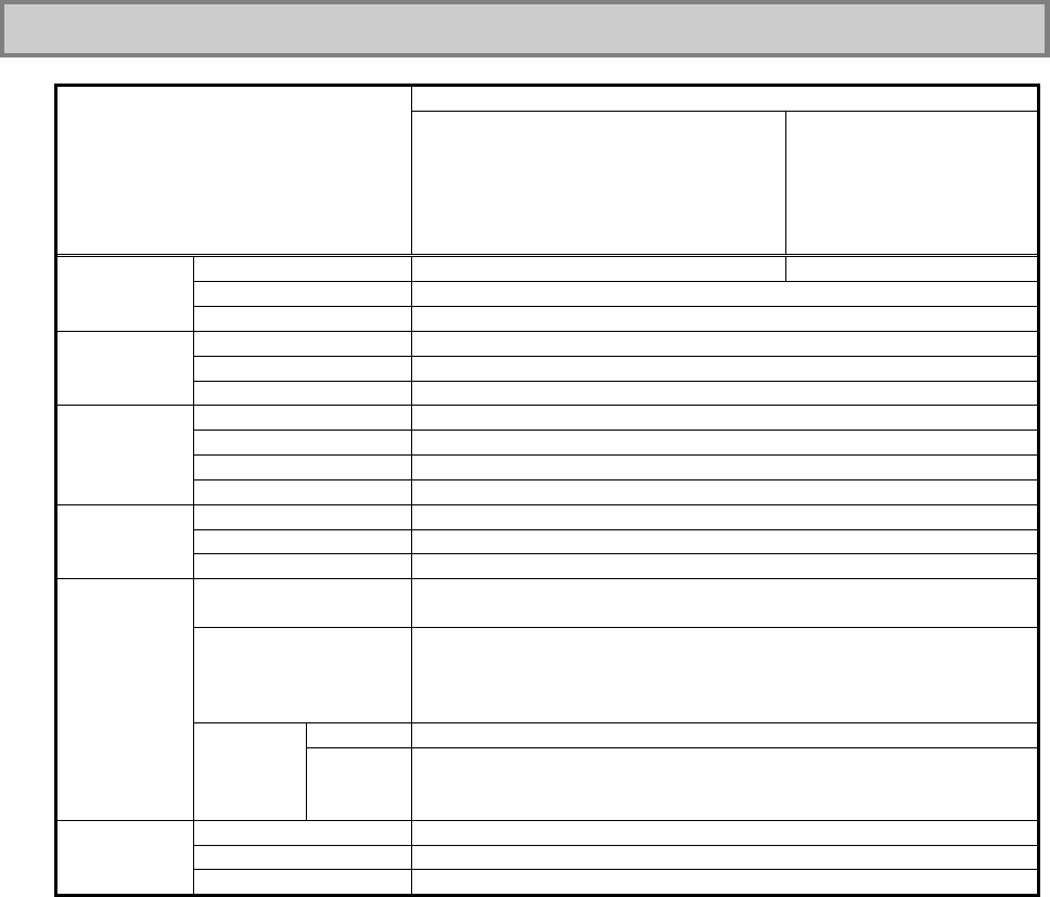
31
1.1.3 Environmental Specification (Main Unit)
Item Condition
Installation of standard hard disk drive
and battery
Installation of silicon disk drive and
standard battery
Installation of silicon disk drive and
stamina standard battery
Installation of hard disk
drive and battery of wide
temperature range
Operating 5 to 45 ºC (Note 2) -20 to 50ºC (Note 2)
Storage -40 to 70ºC
Temperature
Evaluation standard IEC 68-2-1,2,14 / MIL-STD-810F, Method 501.4, 502.4
Operating 5 to 95% RH (without condensation)
Storage 5 to 95% RH (without condensation)
Humidity
Evaluation standard IEC 68-2-30 / MIL-STD-810F, Method 507.4
Operating 15,000 ft (4,572m)
Storage 40,000 ft (12,190m)
Change rate 2,000 ft/min (609.6 m/min)
Altitude
Evaluation standard IEC 68-2-13 / MIL-STD-810F, Method 500.4
Operating 147 m/s2, 11 ms, half sinusoidal wave
Storage 490 m/s2, 11 ms, half sinusoidal wave
Shock
resistance
(Note 1) Evaluation standard IEC 68-2-27 / MIL-STD-810F, Method 516.5
Operating [Sinusoidal wave] 0.075 mm (0-P) in frequency range 10 to 55 Hz
9.8 m/s2 (0-P) in frequency range 55 to 500 Hz
Storage [Sinusoidal wave] 0.15 mm (0-P) in frequency range 10 to 55 Hz
19.6 m/s2 (0-P) in frequency range 55 to 500 Hz
[Random wave] 0.04G2/Hz in frequency range 20 to 1000 Hz
-6 dB/Octave in frequency range 1000 to 2000 Hz
Operating
Sinusoidal wave: IEC68-2-6
Vibration
resistance
(Note 1)
Evaluation
standard Storage Sinusoidal wave: IEC68-2-6
Random wave: MIL-STD-810F, Method 514.5 Category 24 FIGURE
514.5C-17
Operating IP54
Storage IP54
Dust proof
and drip
proof Evaluation standard IEC 529 / MIL-STD-810F
IEC: Abbreviation for International Electrotechnical Commission.
MIL: Abbreviation for Military Specifications and Standards.
Note 1: The vibration resistance of N22A does not assure that it has sufficient strength against resonance
generated when the frequency of added vibration is close to the natural frequency of N22A.
Note 2: Use the product with an ambient temperature of from 5ºC to 40ºC in tablet mode or while the battery is
being charged.
* The specification does not assure that N22A can operate continuously under the described environmental
conditions in which N22A is installed.
In addition, if N22A is equipped with one or more NEC or commercial options, the most severe environmental
condition among those for N22A and the options is applied. Installation environment conditions for external
optional devices are different that those for the main unit, see the document that comes with each device for
detailed conditions.
When N22A is stored at high/low temperatures, the clock built in N22A may be shifted. Set the clock before
N22A is used again.

32
1.2 CHECKING ACCESSORIES
The following accessories are included in the N22A package box. Check the accessories with
the component list below.
List of N22A Components
Item
No. Product Name Quantity
1 FC-N22A Main Unit 1
2 AC Adapter (Cable length: 1.8 m) 1
3 Power Cord (2.0 m) *1 1
4 Battery 1
5 Getting Started *2 1 copy
6 Warranty 1 copy
7 Recovery DVD-ROM *4 1 set
8 Backup CD-ROM (OS not included) *2 *3 *4 1 set
9 Touch Pen 1
10 Pre-installed Windows® XP License Agreement (English) 1 copy
11 Anti-theft screws (M2×4 screw (Black))
4
(including
2 spare screws)
*1: The attached power code is dedicated to 100 VAC.
*2: An electrical manual including the same contents as the User’s Manual is stored on the “Backup CD-ROM”.
*3: Attached application software and electrical manuals are stored.
Included software and electrical manuals are stored on the Recovery DVD-ROM.
*4: The optional external CD-R/RW with DVD-ROM drive is required.
Copies of notes not listed in this list may be included in the accessories.
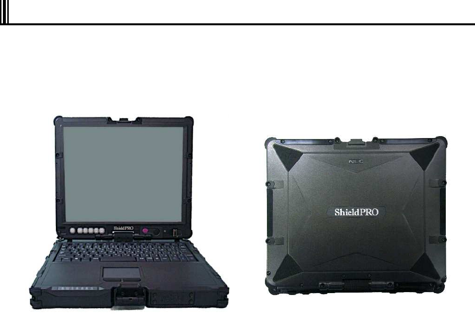
33
1.3 EXTERIOR VIEW
N22A is of convertible type allowing it to be used as a note or tablet PC depending on uses.
N22A also has several characteristics including light weight, various security features and
installation of touch panel to be user-friendly.
On its bottom surface of N22A, the hard disk drive, expanded RAM board and battery pack can
be replaced with spares.
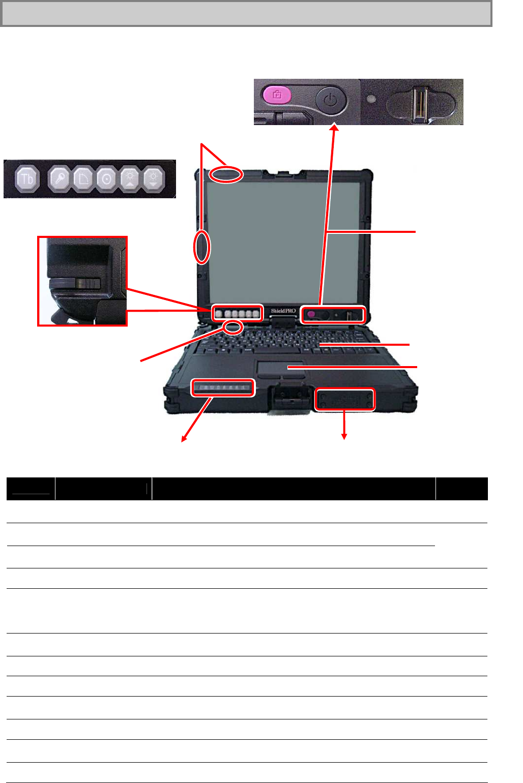
34
1.3.1 Names and Features of Sections of N22A
(1) Inner panels
No. Name Description Reference
page
(1) LCD display
(with touch panel) 12.1-in. TFT LCD display P57
(2) Power lock switch Locks the power switch to prevent the switch from being set
unintentionally (enabled by BIOS setting).
(3) Power switch Allows you to turn on/off power.
Pxx
(4) Fingerprint sensor Reads fingerprint (selection). P70
(5) Tablet buttons
Allows the screen rotation and LCD brightness adjustment features to
be executed directly.
Setting BIOS appropriately, you can assign any key codes to these
buttons.
Pxx
(6) Touch pen
storage area Stores the attached touch pen. Pxx
(7) Keyboard P51
(8) Touch pad Pxx
(9) Built-in speaker
(monaural) Monaural speaker (0.5 W output) for playing sound.
(10) Indicator lamps Each lamp indicates part statuses, such as the power supply status.
(11) Wireless LAN
Antenna Built-in Wireless LAN Antenna (selection)
(12) Bluetooth Antenna Built-in Bluetooth Antenna (selection)
(2)
(3)
(4)
(5)
(6)
(7)
(8)
(10)
(9)
(1)
(12)
(11)
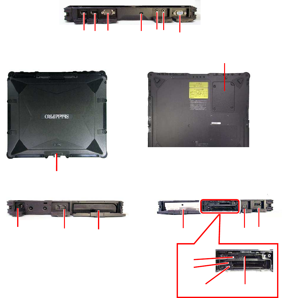
35
(2) Outside sections
(11)
(12)
(1)
(2)
(4)
(5)
(18)
[Right side view]
[Front view] [Bottom view]
[Rear view]
(6)
(13)
(3)
(10)
(7)
(9)
(19)
[Left side view]
(8)
(14)
(15)
(16)
(17)

36
No. Name Description Reference
page
(1) USB connector (2) Connects with a USB device (USB2.0 available). P72
(2) USB connector (3) Connects with a USB device (USB2.0 available). P72
(3) Serial connector Connects with a serial device such as a modem. Pxx
(4) Antitheft lock Connects with a commercial security cable. Pxx
(5) Mike terminal (stereo)
Connects with a commercial microphone.
Connect a 3.5 mm plug to this jack. (stereo and mini jack type)
Some devices may not be directly connected to this machine because of
the connector shape specifications. In such a case, use a commercially
available conversion cable.
(6) Output terminal common
to line and headphone
(stereo)
Outputs sounds to a commercial audio device or headphone (stereo and
mini jack type) Connect a 3.5 mm plug to this jack.
Connect an audio device with an internal amplifier, according to the
usage. Some devices may not directly connect to this machine because
of the connector shape specifications. In such a case, use a
commercially available conversion cable.
(7) External monitor output
connector Connects with an external analog RGB monitor. Pxx
(8) LCD display fixing lock Locks the LCD display. P43
(9) Expanded memory
storage area Stores expanded RAM board of an option. See the explanation of
expanded memory, in the manual that comes with the option.
(10) Power connector Connect an AC adapter or a car adapter. Pxx
(11) LAN (1000BASE-T)
connector Connects with LAN (1000BASE-T/100BASE-TX/10BASE-T) cable. P74
(12) Battery storage area Stores the attached battery. Pxx
(13) Disk drive storage area Stores disk/silicon disk drives (installed). P82
(14) Wireless communication
switch Switches wireless communication devices such as wireless LAN or
Bluetooth devices. Pxx
(15) Express card slot Insert the Express card P66
(16) PC card slot Connects with a PC card (PCMCIA of type II) for feature expansion. P66
(17) Triple memory slot Insert an SD card or a memory stick into this slot. P69
(18) IEEE 1394 connector
(4-pin) Connect a peripheral device, such as a digital video camera, to this
connector. P73
(19) USB connector (1)
(Connect/disconnect-pro
of enhanced type) Connects with a USB device (USB2.0 available). P72
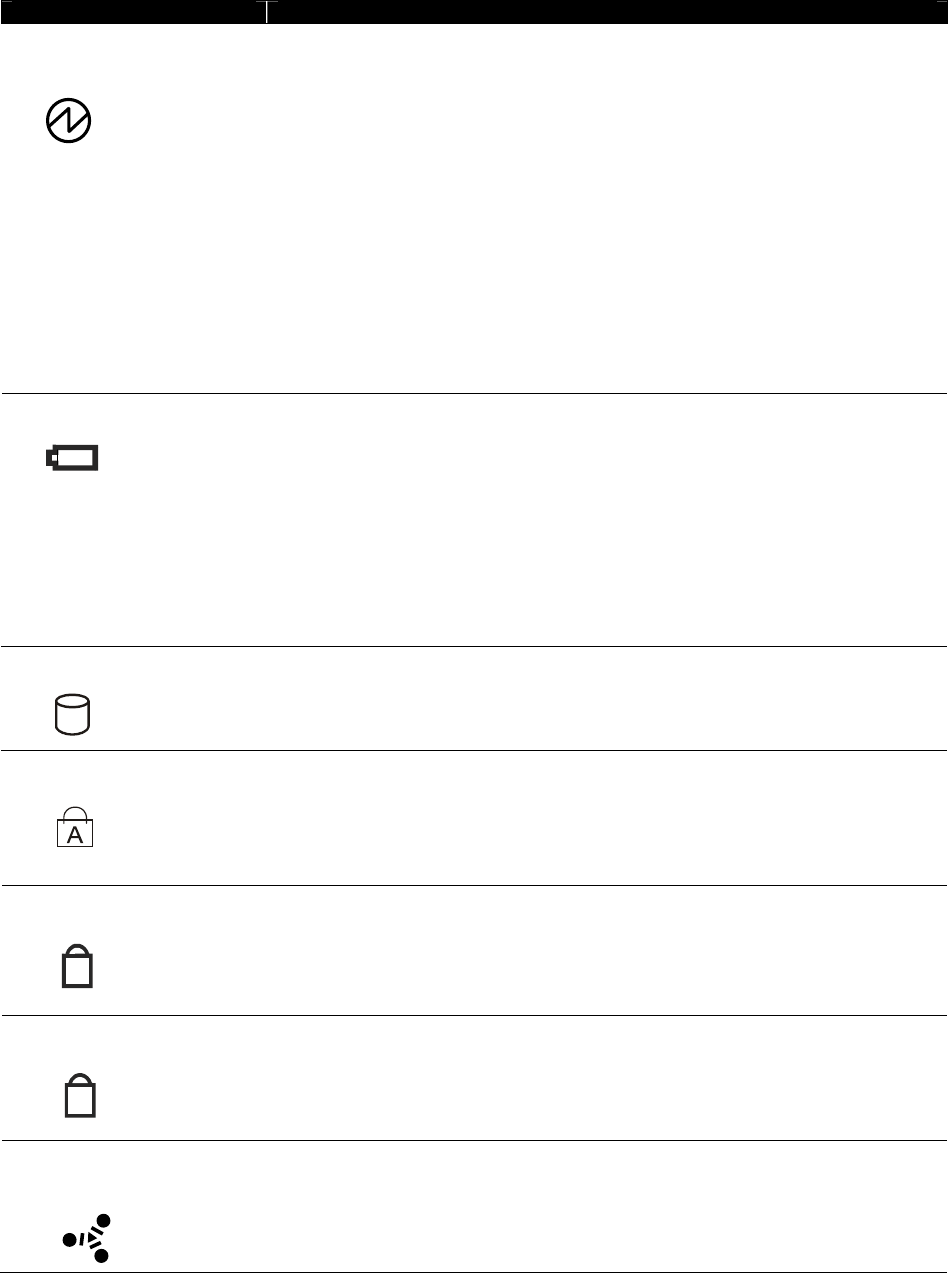
37
(3) Indicator lamps
Name Description
While power is supplied to N22A, the lamp illuminates or blinks in several colors
depending on the status of N22A or the remaining battery level as follows:
Illuminating in green: Power-on status
Blinking in green: Suspend (standby) status
Illuminating in red: Low battery level (7 to 10% of the full level)
Blinking in red
(at 1 sec. in red / off at
2 sec.):
Low battery level in suspend (standby) state (7 to 10% of
the full level)
Blinking in red
(at 0.5 sec. intervals):
Extremely low battery level in suspend (standby) state
(0 to 6% of the full level)
Illuminating in red and
green alternately
AC adapter voltage abnormality
Power lamp
OFF: Power-off status or in hibernate mode
Indicates battery status.
Charging
Illuminating in orange:
Blinking in orange
(at 1 sec. intervals):
Stop charging of the battery because of the ambient
temperature.
Blinking in orange
(at 0.5 sec. intervals):
Occurrence of error
Battery charge lamp
OFF: Discharging, full discharge in no connection of AC
adapter or full charge completed
Disk access lamp
Illuminating (blinking) in green indicates built-in HDD/silicon disk activity.
Indicates whether the caps lock feature is enabled or disabled.
Caps lock key lamp
Illuminating in green:
OFF:
Caps lock feature enabled with Caps Lock pressed once
Caps lock feature disabled with Caps Lock pressed
again
Indicates whether the numeric lock feature is enabled or disabled.
Numeric lock key lamp Illuminating in green:
OFF:
Numeral lock feature enabled with Num Lk pressed
once
Numeral lock feature disabled with Num Lk pressed
again
Indicates whether the scroll lock feature is enabled or disabled.
Scroll lock key lamp Illuminating in green:
OFF:
Scroll lock feature is enabled by pressing the Scr Lk key
once.
Scroll lock feature is disabled by pressing the Scr Lk
key again.
Indicates the use status of the wireless communication feature, wireless LAN or
Bluetooth.
Wireless communication lamp
(only for models with wireless
communication feature)
Illuminating in blue:
OFF:
Wireless communication feature is enabled.
Wireless communication feature is disabled.
1
⇅

38
1.4 INSTALLATION GUIDE
From Installing to Operating
Steps from installation to operations are shown in the following flow.
Introduction Chapter 1” Preparation”
↓
Checking installation environment Chapter 1 “Preparation SPECIFICATIONS”
↓
Installing/Mounting Chapter 1 “Preparation INSTALLATION GUIDE”
↓
Installing the battery Chapter 1 “Preparation INSTALLING BATTERY”
↓
Setting BIOS Chapter 4 “Setting BIOS”
↓
Installing and setting up operating system Chapter 5 “Installing OS and Applications”
↓
Installing application software Chapter 5 “Installing OS and Applications”
↓
Verifying system operations
↓
Carriage and storage Chapter 6 “Maintenance”
↓
Maintenance Chapter 6 “Maintenance”
(1) Notes on installation place
Install N22A in a place where it can be operated properly. See “Notes on Use of N22A in
FA Environment” for details.
(2) Notes on operation
1. Before connecting or disconnecting cables to/from peripherals (excluding USB devices
and PC and SD cards), confirm that the power of N22A is OFF. Connecting or
disconnecting the relevant cable to/from a peripheral with the power of N22A being ON
may cause a malfunction or fault to occur.
2. After turning off the power of N22A, wait for five seconds or longer before the power is
turned on again. Turning on the power just after turn-off without a certain interval may
cause a malfunction or fault to occur.
3. Clean N22A periodically.
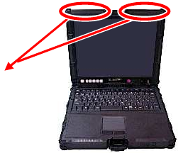
39
(3) Notes on storage and use environment of N22A
1. N22A is a VCCI Class B information technology equipment (or information equipment
mainly intended to be used in household environments) conforming to the reference
level of the Voluntary Control Council for Interference by Information Technology
Equipment (VCCI).
However, if N22A is used near a radio, TV and/or wireless device, N22A may cause
poor receptions.
On the other hand, a device generating intense magnetic field is located near N22A,
noises may have bad influence on N22A to operate inappropriately. If this occurs, take
N22A away from such a device.
2. To use N22A in an FA environment, always make N22A meet the conditions described
in “1.1.3 Environmental Specification (Main Unit)”.
(4) Notes on handling and use of HDD
Hard disk drives are precision devices.
N22A can protect the built-in hard disk drive with buffer materials. However, note the
following to protect data.
1. Do not apply shocks and vibrations exceeding over those defined in the environmental
specification to N22A.
2. Keep hard disk in the hard disk drive from being subject to strong shocks if the drive is
removed from N22A.
(5) Notes on handling of devices sensitive to magnetism (including floppy disks)
A magnet to sense opening or closing of the LCD display panel is contained at the upper
left corner of the panel.
The magnet may destroy data saved in magnetic media. Do not put devices sensitive to
magnetism (including floppy disks) close to the magnet.
Magnet
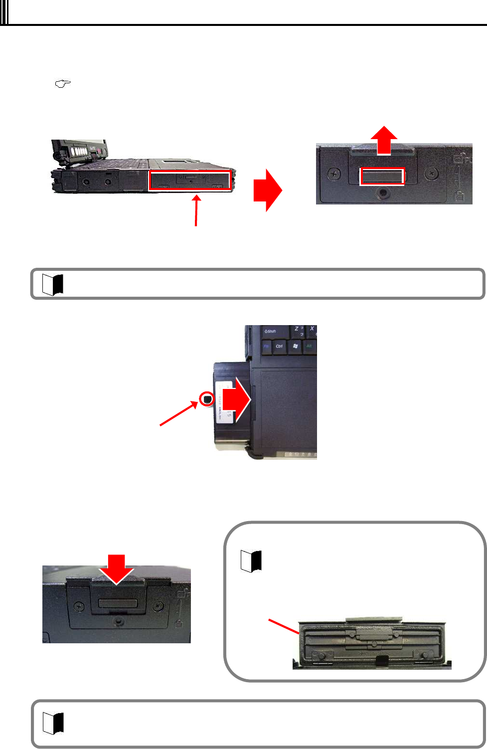
40
1.5 INSTALLING BATTERY
1 Turn off the N22A and remove the AC adapter or car adapter.
2 Unlock the LCD display to open the LCD panel.
( See “Opening/Closing LCD Display Panel and Setting Tablet Mode” in “Chapter 2. Uses of N22A”.)
3 While pressing the button of the battery cover on the left side, slide the cover upward
to open it.
4 Insert the battery horizontally until it is securely connected.
5 Close the battery cover, and then press the top part to return it to the original
position.
Battery cover
The battery is not charged enough at shipment of N22A from factory. Charge before use.
When using the N22A for the first time, connecting it to the power supply automatically
starts battery charging.
Install the battery with the battery removal support pulled out.
Battery removal
support
If dust and/or dirt adhere to the drip-proof
packing on rear of the cover, the dust-proof and
the drip-proof performance of the cover may be
reduced. Wipe the drip-proof packing to remove
dust and dirt before installing the cover.
Drip-proof packing
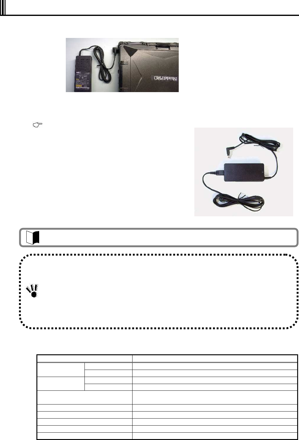
41
1.6 INSTALLING AC ADAPTER
1 Insert the DC plug of the AC adapter into the power connector on the left side.
2 Connect the attached power cord to the AC adapter.
3 Plug the power cable into the power outlet.
Charging of the battery automatically starts.
( See “Battery” in “Chapter 2 Uses of N22A”.)
The AC adapter operates in the range
between 100 and 240 VAC.
The power cable accompanying with
the N22A is designed for 100 V
operation only. Note that it cannot be
used with an input voltage exceeding
125 VAC.
(1) Specification of AC adapter
Item Specification
Operating -20 to 50ºC Temperature
Storage -20 to 70ºC
Operating 25 to 85% RH (without condensation) Humidity
Storage 10 to 90% RH (without condensation)
Input voltage 100 to 240 VAC (±10%), 1.1 to 0.5 A, 50/60 Hz (±5%)
(The AC cord can be exclusively used for 100 VAC.)
Output voltage 16 VDC (±7%), 4.0 A
Maximum power 56 W
Cable length 1.8 m (AC cord: about 2 m)
Outside dimension 140 (W) × 63 (D) × 30.5 (H) mm
Weight About 0.5 kg (including AC cord)
The AC adapter and power cable accompanying the N22A are designed for use only with the
N22A and the battery charger (optional, FC-BC01N). Do not use them for other devices. If the
AC adapter is connected to another device, it may be damaged.
The AC cord attached to N22A is intended to be used only in Japan. If you want to use N22A in
a country other than Japan, contact your service representative on the proper power cord.
Unplug the AC adapter from the outlet first, and then disconnect the N22A or battery charger
end. If it is removed in the reverse order, the AC adapter, N22A, or battery charger may be
damaged.
Always hold each plug of the AC adapter in its removal. Do not pull the cord.
The car adapter (optional, FC-VA01N) can be used for the power supply.
42
THIS PAGE INTENTIONALLY LEFT BLANK.
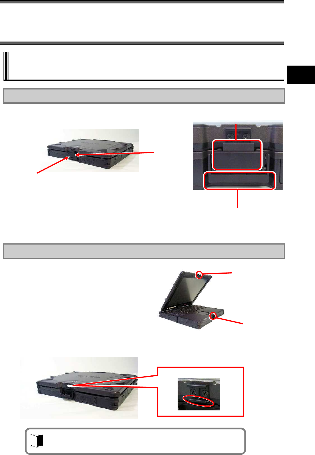
43
Uses of N22A
Chapter 2 Uses of N22A
2.1 OPENING/CLOSING LCD DISPLAY PANEL
AND SETTING TABLET MODE
2.1.1 Opening Panel
1 Pull up latch A and unhook latch B.
2 Open the LCD display panel.
2.1.2 Closing Panel
1 Fit the guide support on the base unit
to the guide on the LCD display panel
and close the panel.
2 Pull up latch A.
3 Hook latch B on the LCD display panel
and pull down latch A to fix the display
panel.
Unlatch
latch B.
latch A
Pull up latch A.
* LCD display lock consists of latches A and B.
latch B
Guides on display
panel
Guide support
on base unit
Hook latch B on the position.
If latch B is hooked improperly, check if the guide on the LCD display is
securely fit to the guide support on the base unit.
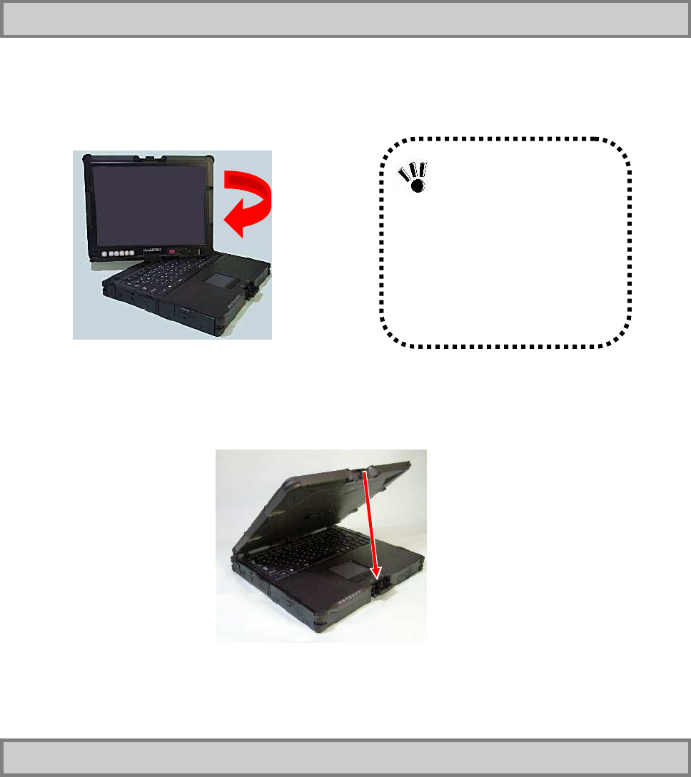
44
2.1.3 Turning Screen (to be in tablet mode)
1 Get the LCD display panel upright.
2 Turn the LCD display panel clockwise by 180º.
3 Fit the guide on the display panel to the guide support on the base unit and close the
panel with the LCD display facing upward.
4 Pull up latch A.
5 Hook latch B on the LCD display panel and pull down latch A to fix the LCD display
panel.
2.1.4 Returning Screen to its Original Position
1 Pull up latch A to unhook latch B.
2 Get the LCD display panel upright.
3 Turn the LCD display panel counterclockwise by 180º.
Do not turn the LCD
display panel clockwise by
larger than 180º or
counterclockwise.
Be careful not to pinch
your fingers while rotating
the LCD display panel.
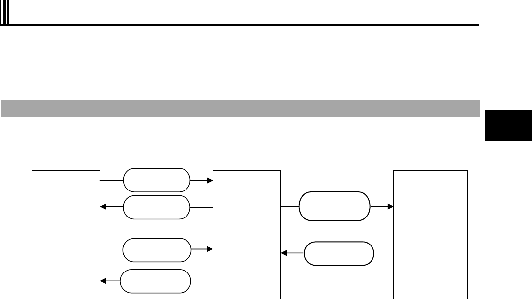
45
Uses of N22A
2.2 TURNING ON/OFF POWER
This section describes how to turn on or off the power of N22A and power saving features
(including suspend (standby) and pause states).
Take special note on turning off the power. If you turn off the power of N22A improperly, not
only data and programs but also the machine itself may be broken.
Power states
The power states of N22A is divided into four states, or power-off, power-on, suspend (standby)
and pause states. These states are changed as follows:
(1) Power-off state
In the power-off state, N22A is not used at all due to shutdown of Windows or another exit
operation.
(2) Power-on state
In the power-on state, N22A is used normally.
(3) Suspend (standby) state
Suspend (standby) is a power saving state where the power to the hard disk drive is shut
off. The power supply of the N22A is not completely shut off. In this state, the working
data is temporarily saved in memory and necessary power is supplied to keep the data in
the memory.
Because working data is saved in memory, N22A can immediately return to the original
state at recovery from the suspend (standby) state.
* Some OSs cannot enter N22A into the suspend (standby) state.
(4) Pause state
When the N22A enters the hibernate state, all data in the memory is saved to the hard disk
and power to the N22A goes off without exiting Windows.
If the power is turned on again, N22A is recovered to the same state as that at the
power-off. Due to the power-off, it takes a longer time for recovery from the pause state
than for recovery from the suspend (standby) state.
* Some OSs cannot enter N22A into the pause state.
See “Indicator lamps” of “Names and Features of Sections of FC-N22A” in “Chapter 1
Preparation” for details on the indicator lamp display according to the power status.
(1) Power-off
state
or
(4) Pause state
(2) Power-on
state
(3) Suspend
(standby)
state
Turn on power.
Turn off power.
Suspend
(Standby)
Resume
Return from
pause state
Enter into pause
state
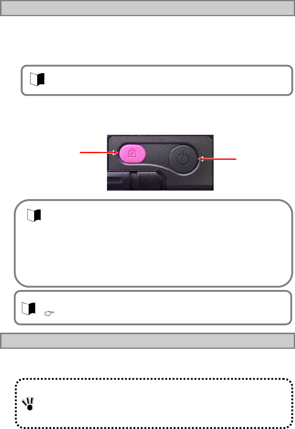
46
2.2.1 Turning on Power
To turn on the power in the power-off state, be sure to follow the procedure described below.
To turn on the power again, wait for five seconds or longer after power-off.
1 Turn on the peripheral devices.
2 Press the power switch for one second.
The N22A is turned on and the power lamp glows.
2.2.2 Turning off Power (shutdown)
Turn off the N22A when it will not be used for a long time as well as before connecting devices
to it.
Power lock
release switch Power switch
Some peripheral devices may be recognized properly only when their powers are turned
on before turning on the power of N22A.
Refer to the User's Guides of peripheral devices previously.
- For memory initialization, it may take some time to allow the initial screen to appear
after power-on.
- For the power lock release switch, see “Chapter 4 Setting BIOS”.
- Press the power switch continuously for 1 sec or longer.
To avoid operation mistakes, N22A is so designed that the power is turned on only by
pressing the power switch for 1 to 2 sec consciously.
- If N22A is activated only by battery, it takes 1 to 2 sec to turn on LEDs after depression
of the power switch.
This is because N22A is so designed as to prevent battery power from being consumed
by turning off all powers including the standby power in the power-off state. This does
not occur in use of “WakeOnLAN”, since the standby power remains to sense LAN
signals.
- After power-on, do not turn off the power while Windows and one or more applications are
activated. Before turning off the power, confirm that neither the mouse pointer nor the sand
clock appear and the file access LED does not illuminate.
- Pressing the power switch for 4 seconds forcibly turns off power; data that has not been
saved will be lost. Save the working data before pressing the power switch to turn off the
N22A.
The BIOS activation screen appears after power-on. To continue BIOS setting, press the
F2
key. The BIOS setup menu screen then appears.
( See “Chapter 4 Setting BIOS”.)

47
Uses of N22A
Power-off procedure by using Windows End menu
1 Save edited data and quit all the applications.
2 On the Windows® XP screen, click [Start] [Shutdown]. Next, click the [Shutdown]
button.
Do not press the power switch during the shutdown processing.
3 Check that the power is turned off.
After a few seconds, the screen will go dark and the power will turn off automatically.
Check that the power lamp goes off.
4 Turn off the peripheral devices.
Power-off procedure by using power switch
1 Save edited data and quit all the applications.
2 Press the power switch.
3 Check that the power is turned off.
4 Turn off the peripheral devices.
2.2.3 Power Saving Features
The suspend (standby) or hibernate features allow stopping of operation without exiting
applications. When restored, different from shutting down, the screen immediately before the
suspend (standby) or hibernate status is entered allows operation to be immediately started
(resuming).
Notes on using suspend (standby) and resume feature or hibernate status
To use the suspend (standby) and resume features, note the following. Failure to follow these
instructions may cause working data for entering N22A into the suspend (standby) state to be
lost or not to be restored.
Before entering suspend (standby) or hibernate status
When any communication device is being used, quit the communication application before
entering the suspend (standby) or hibernate status. Entering N22A into the suspend
(standby) state under communication may leave the line connected to add up the
communication fee.
Note that entering the hibernate status while communication being performed may forcibly
disconnect communication.
Before N22A can be entered into the suspend (standby) state, USB devices should be
removed from N22A. N22A with one or more USB devices connected may not be able to be
entered into the suspend (standby) state.
48
Do not enter the suspend (standby) or hibernate status in the following cases:
Executing system change job (including setting driver or adding printer),
Outputting data to printer,
Replaying audio or motion picture,
Reading/writing data from/to memory card or hard disk,
Reading/writing data from/to floppy disk, CD-R or DVD-R,
Using application not applicable to the suspend (standby) state feature,
When using a peripheral device or expansion card that does not support the suspend
(standby) and hibernate features
Executing Windows start or exit processing, or
If N22A is entered into the suspend (standby) state during connection to network through fax
modem or LAN by communication software, the network feature is aborted once. Some
applications accessing to network may cause data to be lost when N22A is entered into the
suspend (standby) state. Before using an application accessing to network, contact a system
administrator to check if the suspend (standby) state may be used.
When transiting to the suspend (standby) or hibernate status
Do not replace disks and PC and memory card. Failure to follow this instruction may
cause data to be saved improperly.
Do not connect or disconnect a USB device and IEEE 1394 device to/from N22A.
During suspend (standby) or hibernate status
Power is consumed during the suspend (standby) status. The saved data will be lost
if the battery becomes depleted. Be sure to connect the AC adapter during the
suspend (standby) status.
Do not connect or disconnect peripheral devices, otherwise this product may not
resume normally.
Other notes
If a SCSI PC card is used, N22A cannot be resumed properly depending on the combination
of the SCSI PC card and the connected device.
To make N22A resumed immediately after entering it into the suspend (standby) state, wait
for five seconds or longer from transition to the suspend (standby) state. It is required not to
impose a burden on N22A excessively.
After recovery from the pause state, nothing may appear on the LCD display. In this case,
touch the touch pad (mouse) or press any key to restore the normal display.
Resolution taken if resume feature is executed improperly
The following situations indicate improper execution of the resume feature:
Applications do not operate or
The data having existed before the suspend (standby) state cannot be restored.
The machine will not resume even if the power switch is pressed.
During use of applications causing these situations, do not use the suspend (standby)
and resume features. If N22A cannot be resumed by pressing the power switch, press
the power switch continuously for about four seconds or longer.
The power lamp disappears and the power is turned off forcibly. Then the settings in
the BIOS Setup Menu may return to the factory default values.
Provide settings for the BIOS Setup Menu again if required.
49
Uses of N22A
Setting power saving feature
Perform power saving feature from [Power supply option] of Windows. Operation for manually
executing the power saving feature and the time until the machine automatically enter the
power saving mode can be set.
(1) Changing operation to execute the power saving feature
1. Click [Start] [Control panel] [Performance and maintenance] [Power
option] [Detailed settings] tab.
2. In the [Power button] field, set the operation and the power saving feature to
be executed.
When the power switch is pressed
Select the power saving feature to be executed in [When the power switch of the
computer is pressed].
When the LCD display is closed
Select the power saving feature to be executed in [When the portable computer is
closed].
3. Click the [Apply] button, and then click the [OK] button.
Suspend (standby) state
If you want to suspend jobs on N22A temporarily, you can enter N22A into the suspend
(standby) state to save power consumption.
To suspend (standby) and then resume N22A with the power switch, the setting of the power
switch must be changed.
To enter N22A into the suspend (standby) state in the power-on state manually, follow either of
the procedures below.
(1) Entering the suspend (standby) status
The following three methods are available.
Entering suspend (standby) status from the Windows shutdown menu
Click [Start] [Shutdown option], and then click [Standby].
Close the LCD display
Enabled when [Standby] is selected in [When the portable computer is closed].
Press the power switch
Press the power switch for about one second while the power is on.
The power lamp blinks in green, indicating the suspend (standby) status.
Enabled when [Standby] is selected in [When the power switch of the computer is
pressed].
Before you can suspend (standby) and then resume N22A, wait for five seconds or longer
after change of the power lamp status.
Do not press the power switch for four seconds or longer to suspend (standby) or resume
N22A.
Pressing the power switch for four seconds or longer causes the power to be turned off
forcibly, which results in erasing of unsaved data.
50
(2) Resuming from suspend (standby) status
The following three methods are available.
Press the power switch.
The power lamp illuminates in green and N22A recovers from the suspend (standby)
state (or resumes).
Press any key
Press any key
Open the LCD display
When the N22A has entered into the suspend (standby) status by closing the LCD
display, open the LCD display to resume from the suspend (standby) status.
Pause state
If jobs on N22A are halted for a long period, entering N22A into the pause state allows power
consumption to be saved.
(1) Enabling hibernate status
1. Click [Start] [Control panel] [Performance and maintenance] [Power
option].
2. Click the [Hibernate status] tab, and then select “Enable hibernate status”.
3. Click [OK].
(2) Entering to hibernate status
The following three methods are available.
Enter the hibernate status from the Windows Shutdown menu.
Click [Start] [Turn Off Computer]. Then press Shift and click [Hibernate].
Press the power switch
Enabled when [hibernate] is selected in [When the power switch of the computer is
pressed].
Close the LCD display
Enabled when [hibernate] is selected in [When the portable computer is closed].
(3) Resuming from hibernate status
The following two methods are available.
Press the power switch.
Windows is started to recover the state set when the power was turned off last by
using the pause state feature.
Open the LCD display
When the N22A has entered into the hibernate status by closing the LCD display,
open the LCD display to resume from the hibernate status.
It may take time from closing the LCD display panel until the N22A enters the suspend
(standby) status.
When the time of closing the LCD display is too short, the N22A will not enter the suspend
(standby) status. In this case, close the LCD display panel again.
After recovery from the pause state, nothing may appear on the LCD display. If so, move the
mouse or press any key on the keyboard to allow the display screen to appear properly.
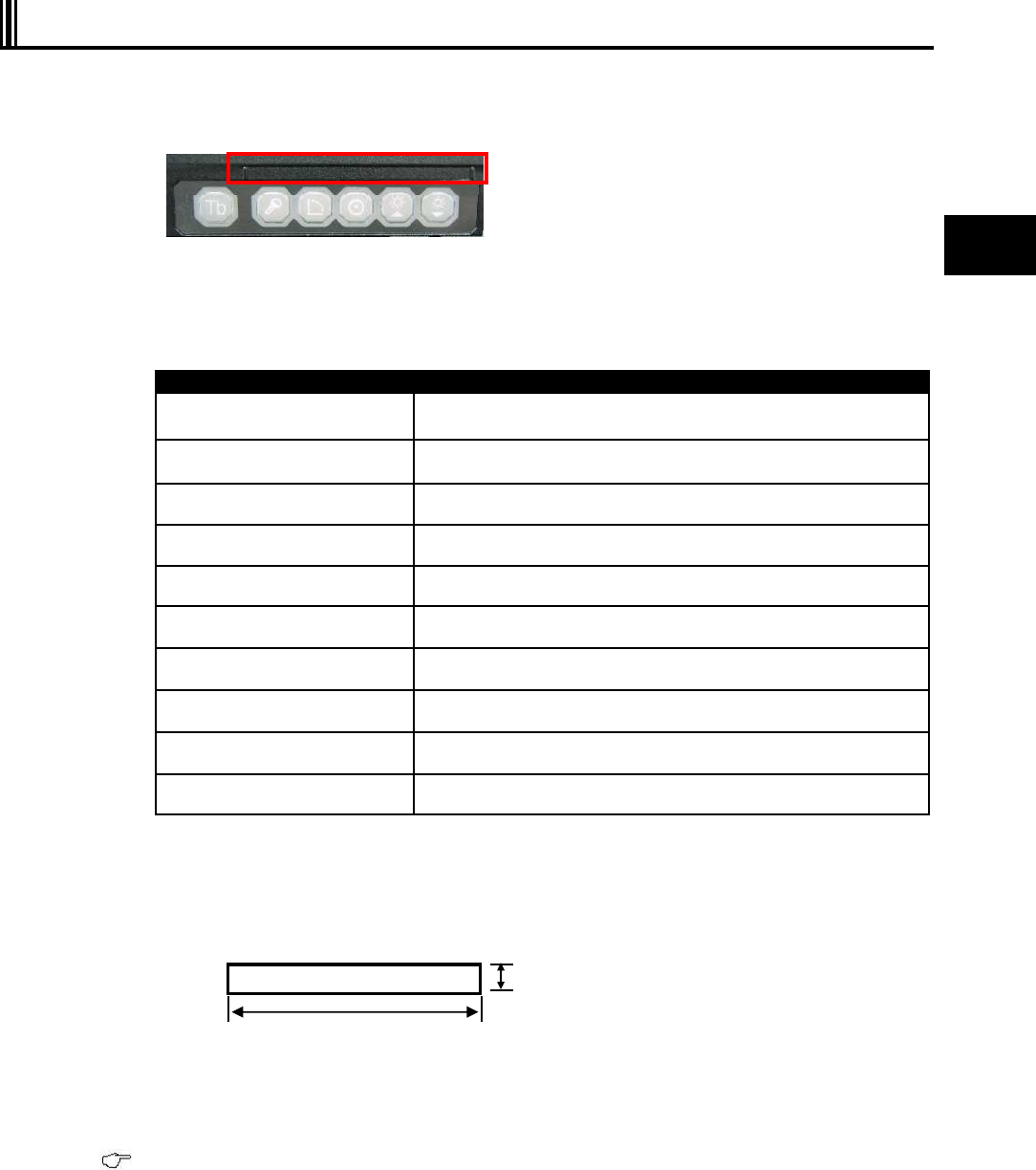
51
Uses of N22A
2.3 TABLET BUTTONS
These buttons enable direct execution of screen rotation, LCD brightness control, etc. Button
assignment can be changed as required.
(Tb) [Tb] button
(1) Tablet button 1
(2) Tablet button 2
(3) Tablet button 3
(4) Tablet button 4
(5) Tablet button 5
(6) Label pasting area
(1) Operations at depression of buttons
Button Operation (defined at shipment)
Tablet button 1 Ctrl + Alt + Del
Tablet button 2 Rotates the Windows screen.
Tablet button 3 Enter
Tablet button 4 Increases brightness of the LCD screen.
Tablet button 5 Decreases brightness of the LCD screen.
[Tb] + Tablet button 1 Esc
[Tb] + Tablet button 2 Tab
[Tb] + Tablet button 3 Starts the screen keyboard.
[Tb] + Tablet button 4 Moves the cursor upward.
[Tb] + Tablet button 5 Moves the cursor downward.
(2) Label pasting area
When key assignment is changed, you can paste a label showing the new key assignment
on the area.
The possible label size is as follows. Prepare the label if required.
Size:
(3) Changing key assignment
Button assignment can be changed from the BIOS setup menu.
( See “Tablet Button Submenu” in “Chapter 4 Setting BIOS.”)
(4) Starting any application
From the BIOS setup menu, assign [FC button 1] and [FC button 2] to enable execution of
the commands (starting application) registered using the FC button setting tool.
For FC button setting tool, see “FC Button Setting Tool” in “Chapter 5 Installing OS and Applications.”
(6)
3mm
60mm
(Tb)
(1)
(2)
(3)
(5)
(4)
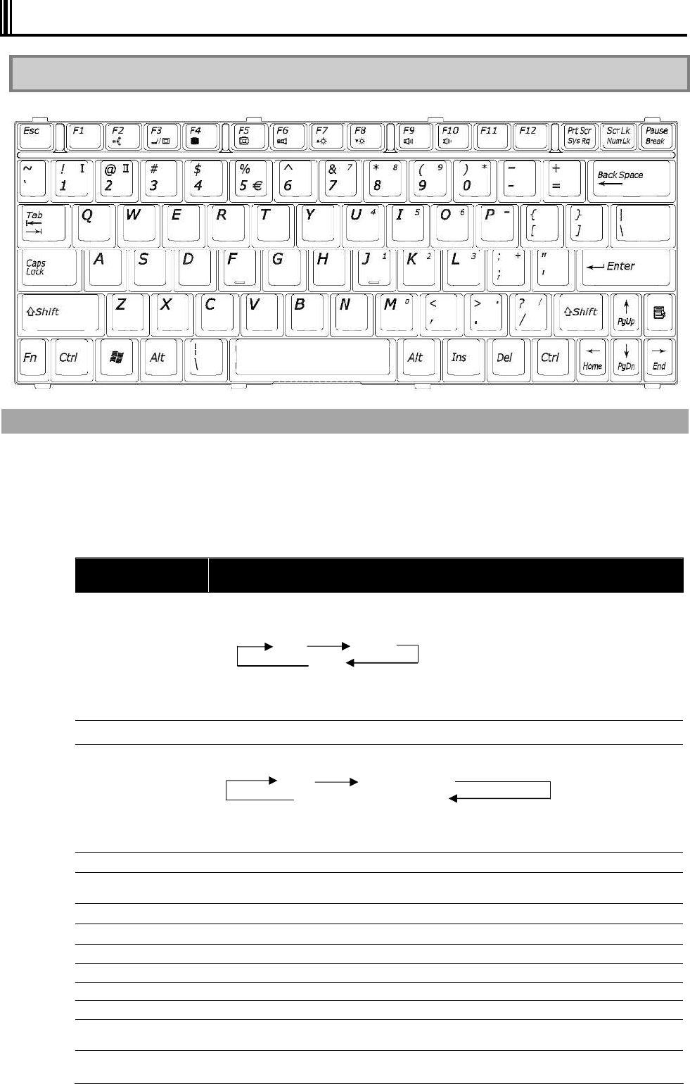
52
2.4 KEYBOARD
2.4.1 English Keyboard
Using Hot Keys [Fn]
Combining Fn with another key allows various operations on N22A to be done easily.
These are called hot key features.
Some icons indicating the features resulting from combinations of respective keys with Fn are
printed on the keys with the same color as Fn.
The table below lists the hot keys and their features.
Key combination Feature or description
Fn+F1
Switches the keyboard backlight from off to on (8 levels). (only for backlight
keyboard).
dark bright
OFF
Note: Switches only between on and off when the keyboard backlight control is set
to [Interlocked] in the BIOS setting.
Fn+F2 Switches the ON/OFF status of the wireless LAN feature. (The external switch is on.)
Fn+F3
Changes the display mode to any of the following three modes if an external monitor
is connected to N22A. (for only Windows XP)
LCD External monitor
Display on both monitors
Note: Alternatives may be limited to “External monitor” and “Display on both
monitors”, depending on the OS used.
Fn+F4 Turns off the backlight of the LCD display.
Fn+F5 Switches enlarged display/no enlarged display of the screen in the low resolution mode.
Some operating systems do not support this feature.
Fn+F6 Disable computer sound (Mute Status)
Fn+F7 Raises the brightness of the LCD display.
Fn+F8 Lowers the brightness of the LCD display.
Fn+F9 Raises the volume of the speakers.
Fn+F10 Lowers the volume of the speakers.
Fn+F11 Switches scroll lock on/off.
Fn+1
Fn+2 FC button
Allows registered application to be started (see Chapter 5).
Fn+PrtScr
(Sys Rq) System request
8 levels
⑤
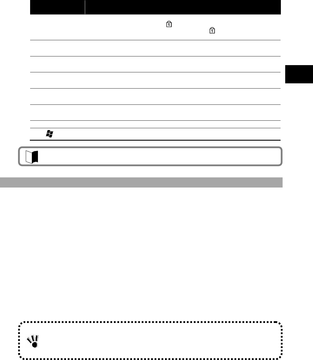
53
Uses of N22A
Key combination Feature or description
Fn+ScrLK
(Num Lk) Numeric lock
If these keys are pressed once, the lamp goes on and blue numerals and symbols
on keys are enabled. If the keys are pressed again, the lamp goes off and normal
characters are enabled.
Fn+Pause
(Break) Break
Fn+
(Page Up) Page Up
Fn+
(Page Dn) Page Dn
Fn+
(Home) Home
Fn+
(End) End
Fn+Alt Right Alt
Fn+ Right Windows
Keyboard with backlight
If a keyboard with backlight is selected from the selection menu, a Japanese keyboard with
backlight is installed. It is suitable for use in a dark place such as a warehouse or at night.
Backlight brightness can be adjusted in 8 levels or off by pressing Fn + F1. It is set to off by
default.
In the [Details] menu of the BIOS settings, set [Keyboard backlight control] to [Interlocked] to
adjust the backlight and LCD brightness at the same time. It is set to [Interlocked] by default. In
this case, press Fn + F7 to increase brightness, or press Fn + F8 to decrease brightness. Press
Fn + F4 to set to “off”.
Keyboard backlight automatically turns off at any of the following events:
When the LCD display panel is closed (opening it resumes the previous status)
When entered into the suspend (standby) status (the previous status resumes by
keyboard or mouse operation)
When entered into the hibernate status (pressing the power switch resumes the
previous status)
The keyboard backlight does not automatically turn off during any of the following events:
When “LCD power off” is set for Power supply option.
When screen saver is being executed.
Press Fn + F1 to turn off the keyboard backlight.
Some OSs and software may disable a part of hot keys to be used.

54
Entering the euro symbol
To enter the euro symbol (€) printed on the 5, change the keyboard layout as described below.
1 Click [Start] [Control Panel].
2 Click [Date, Time, Language, and Regional Option].
3 Click the [Details] button under “Text services and input languages” on the
[Languages] tab.
Note: When the desired keyboard exists in the installed service list, proceed to step 8.
Click the [Add] button under “Installed service”.
4 Select “English (United State)” in the “Input language” list.
5 Select “United States-International” in the “Keyboard layout/IME” list.
6 Click the [OK] button.
7 Select “English (United States)-United States-International” for “Default input
language”.
8 Click the [OK] button.
9 Restart the N22A.
The above settings allow entering the euro symbol (€) by pressing Ctrl + Alt + 5.
55
Uses of N22A
2.5 TOUCH PAD
The touch pad is a pointing device on which you can control the position of the pointer and
select a proper button to communicate with N22A.
The touch pad is composed of a rectangle pad and two buttons. Moving a finger on the pad
allows the pointer on the screen (also called the cursor) to be moved.
If the finger reaches to an end of the pad, let the finger away from the pad and put it at the
opposite end.
Then you can continue to move the pointer.
Term Operation
Point Move a finger on the pad to make the cursor reach to the intended target on the screen.
Click
Press and release the left button,
or
hit the pad lightly.
Double-click
Press and release the left button twice fast,
or
hit the pad twice fast.
Drag & drop
With the left button remaining pressed, move the finger until the cursor reaches to the
intended point (drag). After dragging to the intended point in the selected range, release the
button (drop). The object is dropped at the new point.
or
Tap the pad twice with a finger lightly and leave the finger contact with the pad at the
second tapping. Then move the finger on the pad to drag the selected object to the intended
point. Releasing the finger from the pad, the selected object is dropped at the new point.
Scroll
The scroll means that the display area is altered in the longitudinal or transverse direction
within the working area on the screen.
To alter the display area in the longitudinal direction, put a finger at the right end of the pad
and slide it along the end. To alter the display area in the transverse direction, put a finger at
the bottom of the pad and slide it along the bottom.
The feature can be used only when the touch pad driver attached to N22A is installed.
Some applications may disable the feature to be operated.
Do not make a sharp object such as a ballpoint pen contact with the touch pad.
Failure to follow this instruction may cause the surface of the touch panel to be damaged.
To maintain the optimum performance of the touch pad, keep your fingers and the pad clean
and dry.
Make a finger contact with the pad lightly without excess force.
If “Static” for the pointing device is selected in the selection menu, touch operation with a
gloved hand or a touch pen will not be possible.
56
2.5.1 Setting Touch Pad
Settings of the touch pad can be changed depending on user needs. For example, left-handed
users can interchange the features of the left and right buttons to use the left and right buttons
as the right and left buttons in the normal state, respectively. In addition, the size and
speed of the pointer on the screen may be changed.
1 Display the setting screen.
Click [Start] [Control Panel] [Printers and Other Hardware] [Mouse]. Then the
[Mouse Properties] dialog box appears.
2 Perform settings.
Perform settings on each of the [Buttons], [Pointers], and [Pointer Options] tabs.
3 Click [Apply] and then click [OK].
2.6 TOUCH PANEL
The touch panel feature allows the same operation as the touch pad on the LCD display. Use
the provided touch pen to perform operation on the display.
Term Operation
Point Slide the pen or finger on the touch panel until the cursor reaches to the intended target on
the screen.
Click Tap a point on the touch panel lightly.
Double-click Tap the touch panel twice fast.
Drag & drop Press the touch panel with the pen or finger lightly and slide the pen or finger to the
intended point (drag). After dragging to the intended point in the selected range, release the
pen or finger (drop). The object is dropped at the new point.
If the left and right buttons on the touch pad are interchanged, tapping the touch panel
cannot substitute for pressing the left button.
The features of the touch pad can be enabled/disabled by changing some BIOS settings.
Do not make a sharp object such as a ballpoint pen or a pencil contact with the touch
panel. Failure to follow this instruction may cause the touch panel to be damaged.
If the surface of the touch panel is dirt, wipe the surface with a dry and soft cloth such as
a glass wiping cloth. If manipulating the touch panel with dust adhering on the surface
may cause the surface to be hurt.
Neither put your hands on the surface of the touch panel nor push the surrounding of the
touch panel hard.
The pointer (cursor) may not be operated normally or moved to an end of the screen. While
the touch panel is manipulated, do not put your hands on the keyboard. Failure to follow this
instruction may cause key entries to occur.
57
Uses of N22A
2.6.1 Setting Touch Panel
Setting features
You can change the size and speed of the pointer on the screen. For settings, see “Setting
Touch Pad.”
Compensating position
The position of pointer must be compensated in the following cases:
Changing the resolution of the screen is changed, or
The pointer is not moved properly to the point with which you make the touch pen
contact.
Compensate the point of the pointer in the following procedure:
1 Display the setting screen.
Click [Start] [All Programs] [Gunze TPDD] [Calibrate].
2 Click the four sides specified with red mark × on the screen with the touch pen for
calibration.
Settings on the touch pad are also applied to the touch panel. The touch panel cannot be
independent of the touch pad.
58
2.7 DISPLAY FEATURE
The display features of N22A are characterized as follows:
12.1-in. TFT (Thin-Film Transistor) color LCD display of resolution 1024×768 XGA
(Extended Video Graphics Array)
Concurrent display of both LCD display and external monitor
2.7.1 Display Resolution
The default resolution and the default number of colors are set at shipment of N22A.
For display of a higher resolution, N22A can connect with an external monitor supporting the
higher resolution.
The table below shows the display modes available to N22A.
Display mode LCD display only
Resolution Number of colors
16 bits
800 600 32 bits
16 bits
1024 768 32 bits
* N22A allows external monitors can have resolutions in the range from 640×480 to
1600×1200 and the number of colors of 8, 16 and/or 32 bits. However, the used external
monitor limits available resolutions and the available number of colors.
Notes on color: 8 bits = 256 colors
16 bits = High Color or 65,536 (64 K) colors
32 bits = True Color 16,770,000 (16 M) colors
(16.77 million color display is accomplished by the dithering feature of the graphic
accelerator.)
2.7.2 Adjusting Screen Display
To change the resolution or the number of colors of the screen, follow the procedure below:
1 Open the setting screen.
Click [Start] [Control Panel] [Appearance and Themes] [Display]. Then the [Display
Properties] dialog box appears.
2 Select the [Settings] tab to set the resolution and/or the number of colors of the
screen.
3 Click [Apply] then click [OK].
Some OSs may limit display modes.
To enable the virtual screen feature, follow the procedure below:
On the screen displayed by selecting the [Settings] tab, click the [Advanced] button.
Click the [Monitor] tab.
Click [Hide modes that this monitor cannot display] to uncheck it.
Click [OK].
59
Uses of N22A
2.7.3 Connecting External Monitor
To get a wide display screen of a higher resolution, an external monitor can be connected to
N22A through an external analog RGB monitor connector. Follow the procedure below.
1 Confirm that the power of N22A is OFF.
2 Connect a proper monitor cable to the connector on the external monitor.
3 Turn on the monitor.
4 Turn on the N22A.
If nothing appears on the monitor, press Fn + F3 to select the monitor or both of the monitor
and LCD display (simultaneous display).
Some OSs may limit display modes.
Do not remove the external monitor from N22A in the suspend (standby) mode.
If no external monitor is connected at restart of operations in N22A, the LCD display
remains blank without output.
Some OSs or settings may limit the monitor change by hot keys Fn + F3.
60
2.8 BATTERY
The battery is the power supply built in N22A. The battery can be recharged by using the AC
adapter, optional battery charger FC-BC01N or optional car adapter FC-VA01N.
Installing the charged battery in N22A allows it to be operated without AC power.
The available time of the battery fully charged varies depending on the environment and
condition in which N22A is used. The time may be shortened if applications access to
peripheral devices frequently.
2.8.1 Notes on Batteries
Batteries are consumables. Repeating charging and discharging a battery causes its
charging ability to decrease. Batteries are not charged fully at purchase.
Charge batteries in temperature range 5 to 40ºC. Charging the battery at a higher
temperature may cause it to be deteriorated or damaged.
It takes a longer time to charge the battery fully at a low temperature than to charge it fully
at a normal temperature.
The time taken to charge the battery fully may vary depending on conditions under which
N22A is used.
At a lower temperature, N22A can operate only for a shorter period.
Batteries should be fully charged if possible. Repeating little charge and discharge of the
battery at a low battery level may cause the low remaining battery level to be erroneous.
In use of an external power, leave the battery installed in N22A. This allows the battery to
be kept in the full charge state.
If N22A is not used for a long period (two weeks or longer), remove the battery from N22A.
To remove the battery, do not make the battery pins contact with conductors including
metals and water. Short of the pins may cause the battery to be unavailable.
Save the battery in a low-temperature and dry place if saved. Do not leave the battery in a
place where the temperature exceeds 60ºC.
Do not leave the battery for three months or longer without recharging.
The battery driving time specified in the brochure and User’s Guide of the battery is
calculated based on the battery operation time measurement method (Ver. 1.0) defined by
the Japan Electronics and Information Technology Industries Association.
The actual battery driving time varies depending on the operation environment, the
brightness of the LCD display and the system settings.
When a vibration or shock exceeding the installation environmental conditions is applied to
the N22A with a battery installed, or a strong vibration or shock is applied to a battery itself,
the battery may damaged, resulting in smoke or fire. In this case, stop using the battery.
To use N22A only with the battery, you should often check the remaining battery level.
61
Uses of N22A
2.8.2 Battery Types
Batteries that can be used with the N22A are listed below. Be sure to use a battery of the
same type as the selection menu installation type for your N22A.
Battery type Description
Standard type
(FC-BP01N)
A lithium-ion battery provided with the FC-N22A (standard model and silicon disk
model)
Wide temperature range
type(FC-BP01N/W)
A lithium-ion battery provided with the FC-N22A (HDD wide temperature range
model)
Stamina standard type
(FC-BP01N/L)
A lithium-ion battery provided with the FC-N22A (silicon disk/stamina standard
battery model)
2.8.3 Charging Battery
Charge the battery as shown below.
Connect the AC adapter to N22A and a power outlet
Connect the AC adapter to the battery charger (optional, FC-BC01N) and an outlet.
Connect the car adapter (optional, FC-VA01N) to the N22A and a cigar lighter receptacle.
Connect the car adapter (optional, FC-VA01N) to the battery charger (optional, FC-BC01N)
and a cigar lighter receptacle.
When battery charging starts, the battery LED glows orange to indicate that the battery is being
charged. It is recommended to turn off the power of N22A while the battery is charged.
After the battery is fully charged, the battery charge LED goes off.
It takes about four hours to charge the battery fully.
Battery indicator LED Battery status
Off Battery is not being charged or is fully charged.
Illuminating orange Battery is being charged.
Blinking orange (at 1 sec. intervals) Battery has stoped charging because of the ambient
temperature.
Blinking orange (at 0.5 sec. intervals) Battery error
The battery charge level varies according to the Battery Charge Mode selection in the BIOS
setting. (Normal : 100%, Longlife : 80%, Keeping : 50%, Auto(initial value) : 100% or 80%).
For details, see “Battery Charge Mode” of “Power Management Configuration” in “Chapter 4
Setting BIOS”.
Just after the battery is fully charged, do not take the procedure of removing the AC adapter
from N22A and reconnecting it to start charging again. Failure to follow this instruction may
cause the battery to be damaged.
If an error occurs in the battery, the battery charge LED blinks. The temperature may rise
extraordinary or the battery may be defected. Move N22A to a place of good ventilation or
stop using N22A to lower its temperature.
If the battery charge LED blinks still, remove the AC adapter from N22A and stop using it.
Contact your service representative.
The battery is not charged any more if its temperature exceeds the range of 5 to 50ºC.
When charging the battery, do not remove the AC adapter or car adapter until the battery is
fully charged. If the adapter is removed during charging, the battery will not be fully charged.
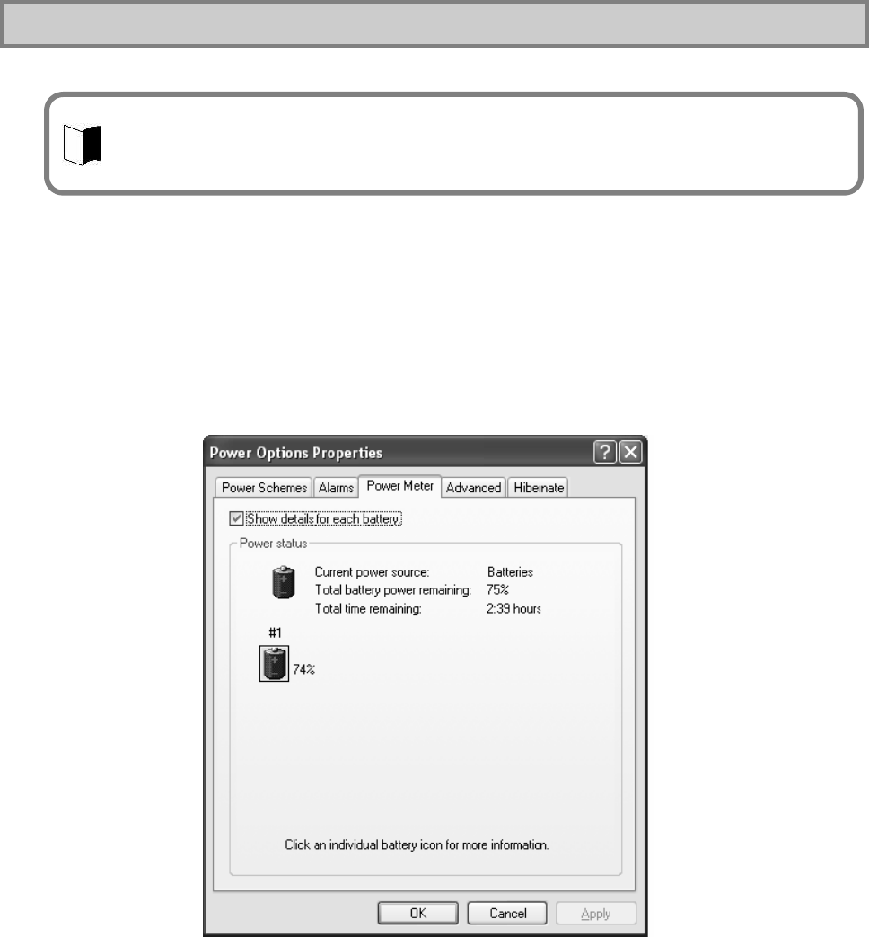
62
2.8.4 Checking Remaining Battery Level
For Windows XP
1. Click [Start] [Control Panel] [Performance and Maintenance] [Power
Options]. Then the [Power Options Properties] dialog box appears.
2. Select the [Power Meter] tab and check [Show details for each battery.].
For Windows XP, the dialog box shown below appears to allow you to check the
remaining battery level.
To activate the screen, wait for several minutes before the AC adapter is disconnected from
N22A.
“Total time remaining” may be different from the actual operation time depending on the
operation status of N22A.
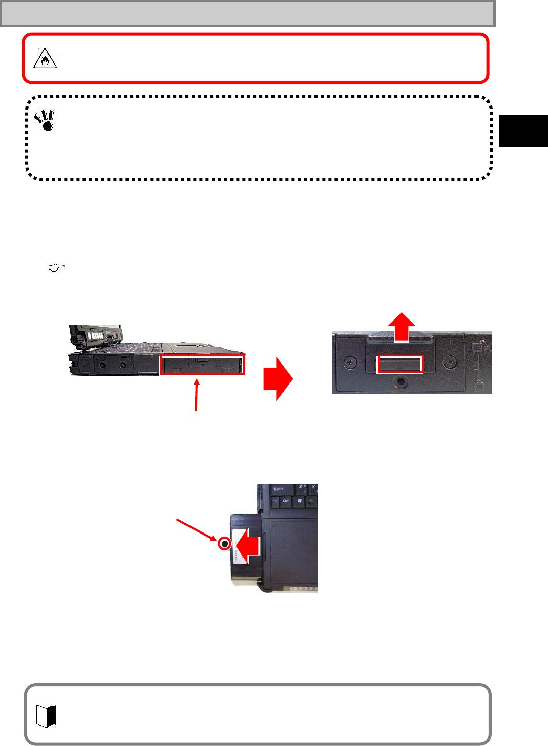
63
Uses of N22A
2.8.5 Replacing Battery
To replace the battery, follow the procedure below:
1 Leave N22A in the power-off state and unplug the AC adapter.
2 Release the LCD display lock, and then open the LCD display panel.
( See “Opening/Closing LCD Display Panel and Setting Tablet Mode” in “Chapter 2 Uses of N22A”)
3 While pressing the battery cover button on the left side, slide the cover upward to
open it.
4 Hold the battery removal support and then pull out the battery horizontally.
5 Insert a new battery into the battery storage area until it is securely connected.
6 Close the battery cover, and then press down the part slid to the original position.
Prepare a new battery valid for the N22A model to be used.
Do not disassemble batteries.
Batteries are consumables. Repeating charging and discharging a battery causes its charging
ability to decrease.
If the full discharging time becomes shorter, initialize the battery. If the time cannot be
recovered still, replace the battery with a spare.
Battery cover
Put the cover so that the battery removal support may not be pinched.
If dust and/or dirt adhere to the sealing material on the rear of the cover, the water-proof and
dust-proof and drip-proof performance of the cover may be reduced. Wipe the sealing material
part to remove dust and dirt before installing the cover.
Battery removal support
If a battery of an invalid type is substituted for the old one, it may explode. Always use a spare
battery of an option. For used batteries, see “6 Recycling Batteries”.
64
Recycling Batteries
A lithium ion battery is used for this product.
Lithiumion batteries are valuable resources being recyclable.
To protect valuable resources, do not dispose batteries becoming unnecessary, but
bring them to any of the following carry-on centers.
* For details of the carry-on centers, see the NEC environmental web page below:
URL:http://www.nec.co.jp/eco/ja/products/3r/indes_denchi.html (As of May 2008)
Notes on handling batteries in recycling
Insulate connectors with tape.
Do not peel off coating.
Do not disassemble batteries.
To keep batteries, enter them in a rugged case and put the lid on the case.
Keep batteries so that they may not get wet with rain.
Do not leave batteries in the sun.
65
Uses of N22A
2.8.6 Actions Taken for Low Battery Charge Level
Decreasing in remaining battery level during battery driving
If the battery power remains only a little, the power LED on N22A illuminates in orange or red to
inform that the battery should be charged
If so, perform either of the following operations depending on situations:
Possible supply of AC power through AC outlet
Connect the AC adapter to an outlet, or connect the car adapter to a cigar lighter
receptacle.
Then the battery charge LED illuminates in orange and battery charge is started.
When power outlet or car cigarette socket is not available
Close applications currently in use, then turn off the power of the N22A.
Setting operation of N22A at low battery level
The operation and state of N22A in a low or no battery charge level can be defined.
1 Logon to it with a user account having the administrator authority.
2 Click [Start] [Control Panel] [Performance and Maintenance] [Power Options].
3 Select the [Alarm] tab when the [Power Option Properties] window appears, then set
for operation settings.
In the lower battery charge level, do not access to a card such as a memory card if used.
Accessing to the card may fail because the time taken for the accessing can be longer than
the full discharging time. If the battery is discharged fully before data storage, the data is lost.
66
2.8.7 Initializing Battery
Initializing the battery is intended to recover its performance decreased temporarily.
The initialization process consists of full charge, full discharge and full recharge of the battery in
the order. It takes about 4.5 hours for the initialization.
Initialize the battery in the following cases:
N22A can be operated by the battery for a shorter period than before.
Repeating battery charging in other than the full discharge state may cause the
full-chargeable level of the battery to be reduced, which then may shorten the driving
period. This is called battery’s memory effect.
Because the battery is just purchased or has not been used for a long period, its
performance is reduced temporarily.
The indicator of the remaining battery level shows some error.
1 Turn off the power of N22A if operated.
2 Install the battery to be initialized.
3 Connect the AC adapter to N22A and the power cord to an AC outlet.
(Connect to a cigar lighter receptacle when using a car adapter.)
If the battery charge lamp blinks, remove the battery pack from N22A once and install it
again.
4 Charge the battery fully.
When the battery is fully charged, the battery LED goes off.
5 Turn on the power of N22A. If the NEC logo screen appears, press F2 to display the
BIOS Setup Menu.
6 Unplug the power cord from the AC outlet and remove the AC adapter from N22A.
(When a car adapter is used, remove the plug from a cigar lighter receptacle and then
remove the car adapter from the N22A.)
7 Select [Battery refresh] in the Power Management menu and press Enter.
8 If message “Refresh your battery now?” select [Yes] and press Enter.
The following dialog box appears.
Refresh battery program
Press Y to start refresh, N to exit
<ESC> to shutdown system
9 Press Y to start battery initialization.
10 Leave N22A until the power is fully discharged.
The power of N22A is automatically turned off.
11 Connect the AC adapter or car adapter to N22A to charge the battery fully.
While the battery is initialized, leave the LCD display panel opened.
To suspend battery initialization, press Ctrl + Alt + Del to reboot N22A or press the power
switch to turn off the power of N22A.
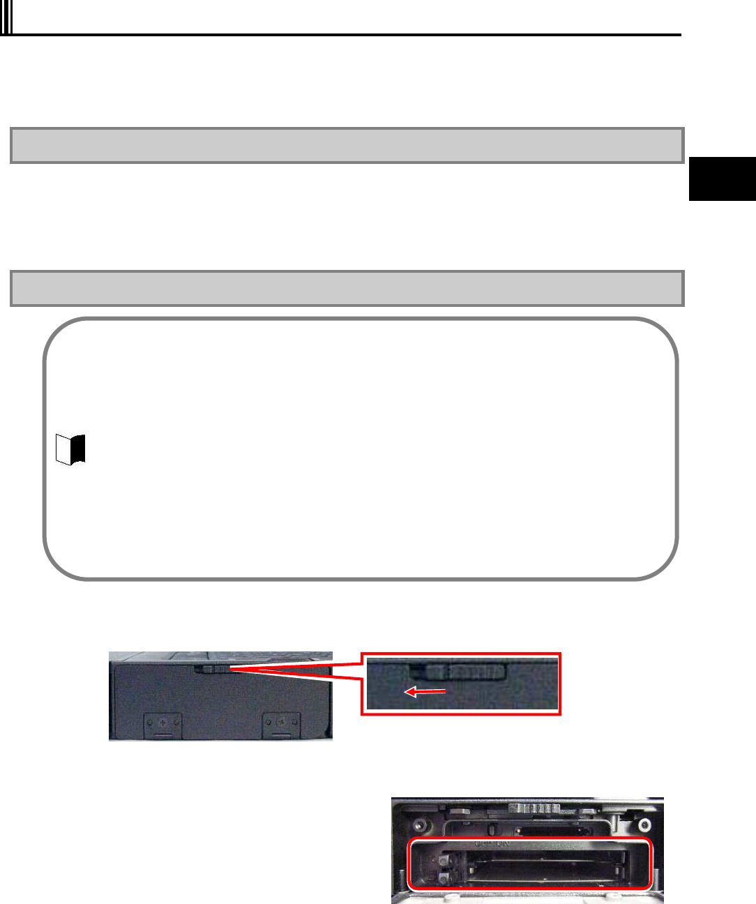
67
Uses of N22A
2.9 PC CARD/EXPRESS CARD
The cards listed below can be inserted into the N22A:
One card of type I or II can be inserted into the PC card slot.
One ExpressCard/34 or ExpressCard/54 card can be inserted into the express card slot.
2.9.1 Supporting CardBus
The PC card slot on FC-21S conforms to the CardBus specification.
The CardBus technology is intended for PC cards of 32-bit version.
This can accomplish the data transfer rate of up to 133Mbps at 33MHz.
SCSI host bus, graphics video and high-speed network cards are available to CardBus.
2.9.2 Installing PC Card in N22A
1 Open the cover on the right side of the N22A.
Slide the knob to the left to unlock the cover.
2 Checking the card slots.
Two card slots are available: the upper for
an express card, the lower for a PC card.
3 Insert the PC card/Express Card into the slot.
When a new card is inserted, the N22A detects it. Install an appropriate driver, according to
the screen instructions.
Some PC cards require certain system resources to be added. When such PC cards are
used, other system resources may have to be released.
The front and rear sides of a PC card are defined and thus the card must be inserted to the
mating slot in the defined orientation. Inserting a PC card to the mating slot in the wrong
orientation forcibly may cause the connector and/or slot to be damaged.
Some PC cards can be inserted to or removed from N22A without turning off the power.
However, any PC card cannot be inserted to or removed from N22A in the suspend (standby)
state.
If N22A is in the suspend (standby) or pause state, do not install or remove a PC card in or
from N22A. Changing the device configuration of N22A may cause data to be lost.
Do not install or remove a PC card in or from N22A while one or more applications operate.
Leave the eject button stored in other than removal of the PC card. Failure to follow this
instruction may cause the card and/or slot to be defected.
Remove a card, observing the proper procedure. Failure to do so may cause the N22A to
malfun
ction.

68
2.9.3 Removing PC Card from N22A
Some PC cards may cause icon [Removing or Taking Out Hardware] to appear on the task tray
at the lower right corner of the screen at the connection.
1 Double-click the icon to display the [Safely Remove Hardware] or [Remove Hardware]
dialog box.
2 Select a device to be removed in the dialog box and click [Stop].
3 “Stop a Hardware device” is indicated. Select the device to be removed and click
[OK].
4 Click [Close] to close the [Safely Remove Hardware] or [Remove Hardware] dialog
box.
5 When the eject button is pushed, the card will pop out a little then pull the card out
entirely from the PC card slot.
69
Uses of N22A
2.10 MEMORY CARD
A triple memory slot is equipped with the N22A supporting the following cards:
SD Memory Card (Secured (with copyright protection))
Memory Stick
Multimedia Card
SDHC Card (Class 6 data transfer speed at 6 MB/sec.)
These cards can be used for file storage, data exchange with a device equipped with a card slot
(including digital video and digital still cameras), music data writing and substitution for
password entry.
2.10.1 Notes on Handling and Storage of SD Card
(1) Do not take the following actions for SD card:
Disassemble or alter SD cards.
Give hard shocks to, bend, drop, and put water on SD cards.
Make hands or metals contact with metallic terminals on SD cards.
Peel off labels on SD cards or put new labels or seals on SD cards.
(2) Do not place SD card in the following places:
Place of increase in temperature (including closed in-car area and location exposed to
direct sunshine)
Place of high temperature and/or much dust
Place of generation of corrosive gas
For details on using “SD Memory Card”, “Memory Stick”, and “SDHC Card”, refer to the
instructions of the manuals included with each card.
Do not use “SD Memory Card”, “Memory Stick”, and “SDHC Card” in locations with static
electricity or electrical noise interference.
It is recommended to use the dedicated device to format the card.
SD cards is applicable to contents delivery services such as Internet (applicable to secure (with
copyright protection feature)).
Always install a mini SD card on an exclusive mini SD card adapter. Insert or remove the adapter
to/from the mating slot. Do not leave the adapter on the slot.
Memory Stick Duo and Memory Stick Pro are supported.
When using a Memory Stick, make sure to attach it to the dedicated adapter, and insert and
remove it together with the adapter.
“MagicGate” (copyright protection function) of Memory Stick is not supported.
Do not insert xD Picture Card as N22A does not support this card. To use xD Picture Card, a
separately sold adapter or USB reader/writer supporting xD Picture Card is required.
The SD card slot on N22A has the data transfer rate of 25MB/sec. *1
If an SD card for higher data transfer rate is used, the rate is limited to 25MB/sec.*1
*1 The data transfer rate is only the theoretical value to be different from the effective rate.
70
2.10.2 Protecting Data
Set the write protect switch on the SD card to the “LOCK” position. Move the switch to the
“LOCK” position for new recording (checkout), editing or file storage.
NEC recommends you to back up important data to other media.
NEC assumes any responsibility for direct and indirect faults including loss of data saved by
customers.
NEC recommends that, if an SD card is disposed, it is destroyed physically by using such a tool
as a hammer to prevent personal data from being flown out.
2.10.3 Installing or Removing SD Card in/from SD Card Slot
Inserting SD Card into SD Card Slot
1 Open the cover on the right side of the N22A.
Slide the knob to the left to unlock the cover.
2 Insert a card from the side with cut corner, facing up the label surface.
Removing SD Card from SD Card Slot
1 Halt the SD card.
1. Double-click the [Safely Remove Hardware] icon on the task tray at the lower
right corner of the screen
2. In the [Safely Remove Hardware] window, click the name of the device to be
removed and then click [Stop].
3. When [Stop of Hardware Device] is displayed, click [OK].
4. Click [Close] to close the [Safely Remove Hardware] window.
The procedure is not required if the SD card is removed in the power-off state.
2 Pushing the SD card allows it to be popped up a little. Then pull out the card.
Before the SD card can be stored, it should be saved in a case.
When an SD card is inserted to the SD card slot, note the orientation of the card. Inserting
an SD card in invalid orientation may cause a fault to occur.
Do not insert/remove a card until the Windows login screen or desktop is displayed.
Wait for about 30 seconds after resuming from the suspend (standby) or hibernate status
before accessing the card.
Before the SD card can be removed, the card must always be halted.
Do not remove the SD card from the SD card slot in any of the following cases. Failure to
follow this instruction may cause important data to be damaged or the SD card to be
accessed improperly at the next installation.
N22A is in the suspend (standby) or pause state,
The SD card opens one or more files (first close the files before removing the SD
card),
The SD card reads of writes data from or to N22A, or
Just after the SD card performs operation such as writing
The SD card may access to N22A intermittently.
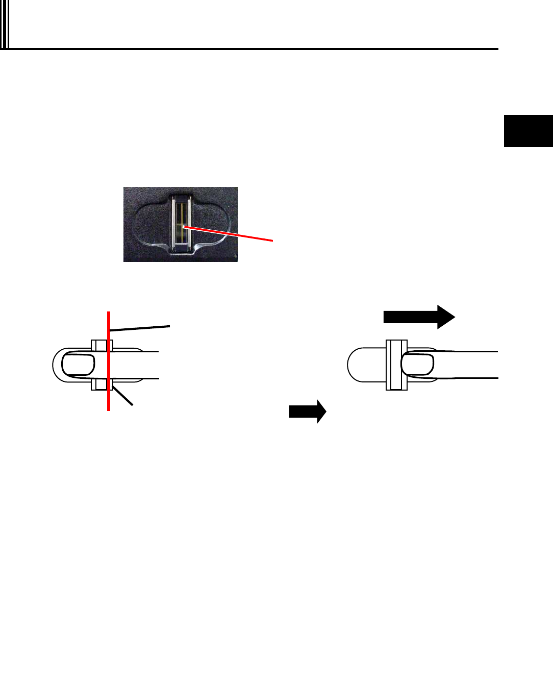
71
Uses of N22A
2.11
FINGERPRINT SENSOR (APPLIED TO FS-N22 OF
FINGERPRINT SENSOR INSTALLATION MODEL ONLY)
N22A of fingerprint sensor installation model can register fingerprint information to enhance
security.
N22A of no fingerprint sensor installation model cannot be equipped with the fingerprint sensor
later.
The fingerprint sensor is intended to read fingerprints. You may pull the registered finger with it
slipped on the sensor to allow the fingerprint to be read.
Security can be enhanced by registering fingerprint information.
See “Fingerprint Authentication Utility” in “Chapter 5 Installing OS and Applications” for details.
Proper finger movement
The fingerprint sensor reads a fingerprint in the range from the top joint to the tip.
Characteristics of fingerprint
It is recommended to register the fingerprints of more than one finger to be registered
easily.
It may be hard to register fingerprint in the following cases:
Grooves of fingerprint are buried with much
sweat and/or skin oil,
Finger is extremely dried,
Fingerprint is too small, Fingerprint is too large,
Fingerprint has no whorls, Hand is in bad condition, or
Fingerprint is weak due to wear. Fingers are much sweat and/or oily in the
summer season,
Fingers are extremely dried in the winter
season,
Fingers are rough or injured, or
Fingers have changed its shape rapidly.
Wipe a finger of sweat and/or skin oil completely or put proper cream on a rough or dry
finger, as necessary.
If your fingertips are small, register as large a finger as possible, i.e., a thumb.
A finger of difficult registration is apt to cause discrepancies in verification.
If all fingers are hard to be registered, registering a specific finger several times can reduce
discrepancies in verification.
Sensor
Put the registered finger
on the sensor with the
top joint located at this
line.
Sensor
(1) Put the registered finger on the
sensor with a line just above the top
joint located at the sensor. Start
moving the finger after a while.
(2) Pull the finger straight and slowly
in parallel with the sensor while
the finger is contact with the
sensor. Note that the finger may
not be detached from the sensor.
72
2.12 COMMUNICATION FEATURE
2.12.1 USB (USB 2.0)
USB is the prefix indicating the Universal Serial Bus. The USB has the defined shapes of
connectors and allows a computer to connect with up to 127 devices.
In addition, the USB provides the plug & play feature to allow the connector of a device to be
connected/disconnected without the power of N22A turned off.
Available USB devices mainly include pointing device, printers, digital cameras, mobile phones
and PHSs.
Connecting USB devices to N22A
N22A has three USB ports intended to connect with USB2.0 devices on the left side.
To connect a USB device to N22A, insert the plug of the USB cable to a USB connector on
N22A.
Removing USB devices from N22A
Some USB devices may cause the icon for removing or taking out hardware to appear on the
task tray at the lower right corner of the screen after the connection.
1 Double-click the icon to display the [Safely Remove Hardware] or [Remove Hardware]
dialog box.
2 Select a device to be removed in the dialog box and click [Stop].
3 “Stop a Hardware device” is indicated. Select the device to be removed and click
[OK].
4 Click [Close] to close the [Safely Remove Hardware] or [Remove Hardware] dialog
box.
Connect/disconnect-proof enhanced connector
USB connector (1) is the connect/disconnect-proof enhanced connector enduring 10,000
combinations of connections and disconnections.
Some USB devices require driver installations and/or switch settings before or after they are
connected to N22A.
Refer to the User's Guides of USB devices to be connected to N22A before using them.
Some USB devices cannot be directly connected to the N22A due to its shape. In such a case,
use a commercially available cable.
After disconnecting a USB device from N22A, wait for three seconds or longer before the device
is connected again.
If the connector of a USB device is connected to a USB connector on N22A quickly or obliquely,
N22A may not be able to read signals properly to recognize it as an unknown device. If so,
remove the connector from the USB connector once and reconnect it again.
When a USB device is connected to N22A, note the orientation of the plug to be inserted to a
USB connector.
Unless a USB device is removed appropriately, N22A may operate improperly. Remove a USB
device in the correct procedure.
Do not connect or remove a USB device to/from N22A in the suspend (standby) state, transition
to the suspend (standby) state, recovery from the suspend (standby) state, the pause state,
transition to the pause state, or recovery from the pause state.
If N22A connects with one or more USB devices, it may not be able to enter into the suspend
(standby) state. Before N22A can be entered into the suspend (standby) state, the USB devices
must be removed.
Some OSs may limit the features of USB devices.
73
Uses of N22A
2.12.2 IEEE 1394 devices
IEEE 1394 devices, such as digital video cameras, can be connected to the N22A.
Installing an IEEE 1394 device
1 Turn on the N22A and the IEEE 1394 device.
2 Open the cover on the right side, and then connect the IEEE 1394 device to the IEEE
1394 connector.
Removing IEEE 1394 device
1 Turn off the N22A and then remove the cable from the IEEE 1394 connector.
Be sure to turn off the N22A before turning off the IEEE 1394 device.
2 Turn off the IEEE 1394 device and then remove the cable.
For some devices, driver installation or switch settings may be required before or after
connection.
Refer to the operation manual for the IEEE 1394 device to be connected before using it.
Wait at least 3 seconds between insertion or removal of an IEEE 1394 device.
Be sure to check the plug insertion direction when connecting an IEEE 1394 device.
Observe the proper procedure for removing an IEEE 1394 device. Failure to do so may
cause malfunction of the N22A.
Do not insert or remove an IEEE 1394 device during the suspend (standby) status, when
entering the suspend (standby) status, when resuming from the suspend (standby)
status, during the hibernate status, when entering the hibernate status, or when resuming
from the hibernate status.
There may be a case where the N22A cannot enter the suspend (standby) status with an
IEEE 1394 device connected. Remove the IEEE 1394 device before entering the
suspend (standby) status.
The IEEE 1394 device function may be limited, depending on the OS to be used.
74
2.12.3 LAN
The built-in 1000BASE-T LAN module allows N22A to connect with network. The module
supports the data transfer rate of up to 1000Mbps.
Connecting N22A to network
1 Insert one end of a LAN cable to the RJ-45 connector (LAN connector) on N22A to the
depth securely.
2 Insert the other end of the LAN cable to the network connector to the depth securely.
Setting LAN
1 Click [Start] [Control Panel] [Network and Internet Connection] [Network
Connections].
2 Double-click [Local Area Connection] to display the [Local Area Connection Status]
dialog box. Click [Properties].
3 The [Local Area Connection Properties] dialog box appears. Provide settings
appropriate for the connected network.
While N22A operates, do not remove the LAN cable from the hub. If removed, the network
connection will be cut out.
If the LAN cable is removed during network connection, immediate re-connection may be
able to recover the operation. If not, restart OS.
During network communication through LAN, connect the AC adapter to N22A. Only the
battery can operate N22A for a rather short period.
The suspend (standby) or pause state disables the network feature. During network
communication, do not enter N22A into the suspend (standby) or pause state.
To run an application using network, enter N22A into the suspend (standby) or pause state
after asking a system administrator to confirm that the application may be used in suspend
(standby) or pause state.
Some applications may cause data to be lost when N22A is recovered from the suspend
(standby) or pause state.
To connect N22A to network, a LAN cable sold separately is required.
For gigabit communications, a cable supporting category 6 or 5e is required.
If you do not know necessary components, contact a system or network administrator.
75
Uses of N22A
Power-on using LAN controller
When the network server is accessed via an internal LAN, the N22A automatically resumes
from the suspend (standby) or hibernate status. When it is off, it is automatically turned on.
To use the power-on using LAN controller by the LAN built in N22A, the following settings are
required.
Settings associated with BIOS Setup Menu (common to OSs)
1. Press F2 on the logon screen. The setup menu is displayed.
2. Select [Power management] from the menu bar and then press Enter. Select
“Power-on using LAN controller”“Enabled”, and then press Enter.
3. Select [Security] from the menu bar, and then select [Network boot setting]
[Keyboard/Mouse Lock] [Disabled], and then press Enter.
4. Press F10 and then select “Yes”.
* Without the setting, keyboard and mouse operations are disabled at remote power-on.
Settings associated with network adaptor
Perform each setting ([Details] and [Power management]) from [Control Panel]
[Network and Internet Connection] [Network Connections] right-click on [Local Area
Connection] [Properties] [Configuration].
Used OS Setting by OS
[Advanced]
Wake from system shutdown [Enable] (setting at shipment)
Wake On Lan Triggers [Automatic] (setting at shipment)
Windows XP
[Power Management]
Check [Allow this device to bring the computer out of standby.].
76
2.12.4 Wireless LAN (applied to N22A of wireless LAN installation
model only)
N22A of wireless LAN installation model allows the wireless LAN feature to be used.
N22A of no wireless LAN installation model cannot be equipped with the wireless LAN feature
later.
Notes on security in use of wireless LAN products
The wireless LAN is advantageous to allow LAN connection freely within the radio wave range
because data is transmitted among wireless access points including computers through radio
waves instead of using LAN cables.
On the other hand, since radio waves reach any locations over obstacles (including walls)
within a certain range, the following problems may occur without security.
Stealing communication data
Malicious outsiders may intentionally intercept radio waves to steal communication data as follows:
− Personal information including IDs, passwords and credit card numbers
− Mail contents
Invading into network illegally
Malicious outsiders may access to personal and corporate networks without notice to take the following actions:
− Acquiring private and confidential information (information leak)
− Make communication as a specific person to spread illegal information (spoofing)
− Rewrites intercepted communication data to be transmitted (falsification)
− Spread computer virus to destroy data and/or systems (destruction)
The N22A provides security settings against the problems mentioned above, for wireless LAN
cards or wireless access points. In nature, wireless LAN cards and wireless access points have
proper security features to cope with these problems. Accordingly, wireless LAN products can
be used with their security features to reduce occurrences of the problems.
The communication speed and distance vary depending on wireless LAN devices and
ambient conditions including radio wave environment, obstacles and installation environment.
Due to the property of radio wave, the communication speed is apt to be slower as the
communication distance is longer. To allow you to use wireless LAN more comfortable, it is
recommended to use wireless LAN devices within a distance as short as possible.
To connect N22A to network, wireless LAN access points sold separately and some other
devices are required.
Using N22A in a country other than Japan may conflict relevant laws in the country.
Accordingly, disable the wireless LAN feature of N22A in other than Japan.
During network communication, do not enter N22A into the pause or suspend (standby) state.
During network communication, connect the AC adapter to N22A. Only the battery can
operate N22A for a rather short period.
For influences on airplanes or medical devices, see “Cautions on using wireless features” in
“For safety”.
Confirm that [Wireless LAN Controller] is set [Enabled] in BIOS Setting when using wireless
LAN. See “PCI Configuration Submenu” in “Chapter4 SETTING BIOS” in detail.
Security settings are not be performed when the N22A is purchased.
77
Uses of N22A
Security enabled by N22A
The wireless LAN installed in N22A has the following security features.
1. Preventing interception
Setting an encryption key by using the encryption feature allows wireless LAN data
among communication devices using the specific encryption key to be encrypted.
However, encryption keys may possibly be known by outsiders or decrypted by
decryption technology. Accordingly, it is recommended to change encryption keys
periodically.
For encryption feature settings, see “Setting encryption feature” of “Wireless LAN” in
this section.
2. Preventing illegal accesses by setting SSIDs (network names)
Setting specific SSIDs (network names) for both access points and communication
devices can avoid connections from communication devices without the same
SSIDs. However, SSIDs can be known by using devices which have the feature of
detecting SSIDs automatically.
To avoid this, SSID hiding must be set on access points not to notify them.
Registering MAC addresses of connected devices in each access point disables
devices not registered to connect to the access point (MAC address filtering). For
setting SSIDs, see “Setting encryption feature” of “Wireless LAN” in this section.
Installing the wireless LAN driver
Install the wireless LAN driver according to the following procedure.
1 Start Windows.
2 Click [Start] [Run…].
3 Click the [Browse] button to select Wireless_TIC_125458_v10.5.1.0_XP32.exe in the
C:¥WINXP¥Drv¥WirelessLAN folder, and then click the [OK] button.
4 The “Important Information” screen is displayed. Check the contents and then click
the [Next] button.
5 The “License Agreement” screen is displayed. Check the contents, select “I accept
the terms in the License agreement”, and then click the [Next] button.
6 The “Location to Save Files” screen is displayed. Check the installation destination
folder and then click the [Next] button.
Wait until the file is expanded.
7 The Intel PROSet/Wireless installer screen is displayed. Click the [Install software]
button.
8 The Intel software license agreement screen is displayed. Select “I accept the terms
in the license agreement”, and then click the [Next] button.
9 The setup type selection screen is displayed. Select “Custom” and then click the
[Next] button.
To provide the following security, used access points should be applicable to the settings. These
settings are only intended to reduce security risks as much as possible but do not assure
complete safety to avoid security risks.
With Standard setup, some features are not installed such as that disabling wireless LAN
connection before logging on to Windows, etc.

78
10 The features selection screen is displayed. Select the necessary features.
To install all sub-features, select “Install this feature and all its sub features” and then click
the [Install] button.
11 When the “Installation completed” screen is displayed, click the [OK] button.
12 When the “Restart” screen is displayed, click the [Yes] button.
13 The N22A is restarted.
Installation of the wireless LAN driver is completed.
On/off of wireless communication
1 Open the cover on the right side of the N22A.
Slide the knob to the left to unlock the cover.
2 Slide the wireless communication switch to the right to turn on/off the wireless
communication device.
The wireless communication lamp will glow blue, indicating that the function can be used.
Sliding the switch to the left will turn the wireless communication function off.
Setting wireless LAN
Perform the following operations.
For Windows XP:
1 Click [Start] [All Programs] [Intel PROSet Wireless].
2 Press Fn + F2 to enable the wireless feature.
If you use wireless LAN for the first time, click [Enable Intel PROSet/Wireless].
3 Connectable wireless networks appears. Select a desired network and click
[Connect]. Provide settings appropriate for the selected network.
4 From the menu bar, select [Tool] [Control tools].
5 The “Create password” screen is displayed. Enter the password and then click the
[OK] button.
6 The “Open administrator package” screen is displayed. Click [Create new package]
and then click the [OK] button.
7 Click the [Profile] button.
8 The “Management tool – new package” screen is displayed. Click the [Add] button.
9 The “Create wireless profile” screen is displayed. Set the information to connect to
the wireless LAN network.
10 When profile setting has completed, click [Close].
Profile name
Enter any profile name (name of a file to which the set parameter information is stored).
Wireless network name (SSID)
Enter the currently used wireless network name.
* If you don't know the wireless network name (SSID), ask your network administrator.
Management profile types
To enable wireless LAN connection before logging on to Windows, select “Before logon/common: Active
during the user is logged in. This profile is shared by all users.”

79
Uses of N22A
11 When “The current package has been changed. Save the changes?” screen is
displayed, click [Yes].
12 The “Save as” screen is displayed. Specify the save destination and file name, and
then click [Save].
13 The “Converting administrator profile to XML” screen is displayed. Click [Browse]
to specify the destination, and then click [Close].
14 When saving completes, click [Finish].
15 The “Package has been saved” screen is displayed. Click “Apply this package to
this computer” and then click the [OK] button.
16 The created profile name is displayed in the “ Intel PROSet Wireless” screen. Click
the profile and then click the [Connect] button.
17 Check if the created profile is connected.
(“Connected” is displayed on the right of the profile name.)
Carefully manage the password.
If the connection for the created profile fails, consult your network administrator.
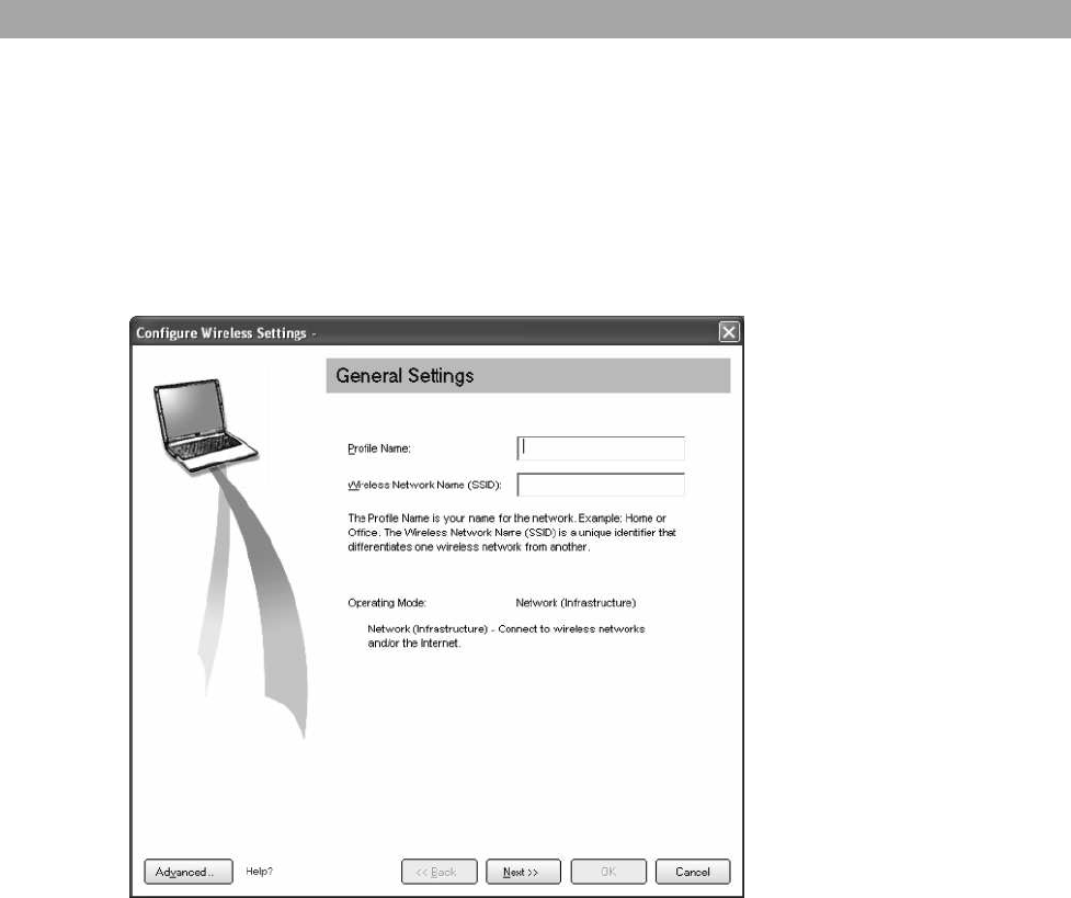
80
Setting SSID feature
Perform the following operations.
For Windows XP:
1. Select a connectable wireless network in the [Intel® PROSet/Wireless] dialog
box and click [Connect].
2. Enter proper names in fields [Profile Name] and [Wireless Network Name
(SSID)].
3. Click [Next]. The [Security Settings] dialog box appears. Go to “Setting WEP
feature”.
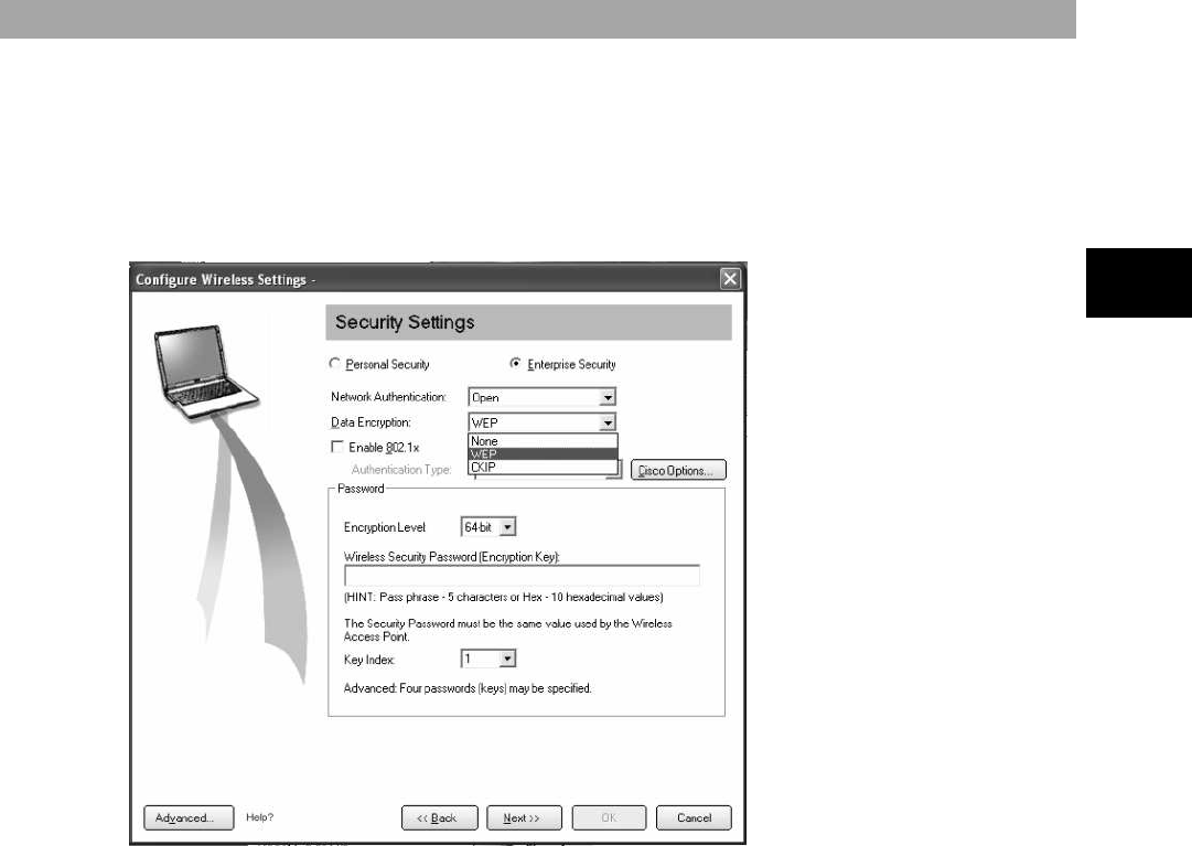
81
Uses of N22A
Setting encryption feature
Perform the following operations.
For Windows XP:
1. In the [Security Settings] dialog box, set the settings appropriate for the
connected wireless network.
Then set the settings follow the directions shown on the display screen.
82
2.12.5 Bluetooth Feature (only for models with this feature installed)
This feature allows access to other Bluetooth devices via wireless connection.
On/off of Bluetooth
Slide the wireless communication switch to turn on Bluetooth feature. (See “On/off of wireless
communication” described previously in this chapter.)
Checking Bluetooth communication status
Put the cursor on the wireless switching icon in the task tray at lower right of the screen.
2.12.6 Serial Port
N22A has a serial port connecting with a serial device including a serial mouse or modem.
To connect a serial device to N22A, follow the procedure below:
1 From the BIOS setup menu, select [Details] [Peripheral devices], and then press
the [Enter] key.
2 Select [Peripheral device submenu] to check that serial port A is enabled.
(For details, see “Chapter 4 Setting BIOS”.)
3 Exit the BIOS setup menu, and then turn off the N22A.
4 Insert the cable of a serial device to the serial port on N22A.
5 Turn on the power of N22A.
N22A cannot connect with a portable modem getting power through the serial port. Use the
built-in battery or a modem using external AC power.
Some OSs may limit serial features.
The communication speed or distance may vary depending on the target Bluetooth device or
peripheral conditions, including radio wave environment, barriers, and installation
environment.
The communication speed is reduced near a microwave oven being used.
To use the Bluetooth feature, set the Bluetooth controller to Enabled (factory default) shown in
the Details menu in “Chapter 4 Setting BIOS”.
During communication, do not enter the hibernate or suspend (standby) status.
During communication, be sure to connect an AC adapter or car adapter to the N22A. Using
it with a battery only results in shorter operating time.
For influences on airplanes or medical devices, see “Cautions on using wireless features” in
“For safety”.
83
Uses of N22A
2.13 HARD DISK DRIVE/SILICON DISK DRIVE
The hard disk drives/silicon disk drives shown below can be used with the N22A.
Disk type Description
Hard disk drive (standard)
(FC-HD80KN/S) A hard disk drive provided with the N22A
(standard model)
Hard disk drive
(wide temperature range)
(FC-HD40KN/S)
A hard disk drive provided with the N22A
(wide temperature range model)
Silicon disk drive
(FC-SD20KN/S) A silicon disk drive provided with the N22A
(silicon disk model)
Be sure to use a hard disk drive of the same type as that in the selection menu installation type
for your N22A.
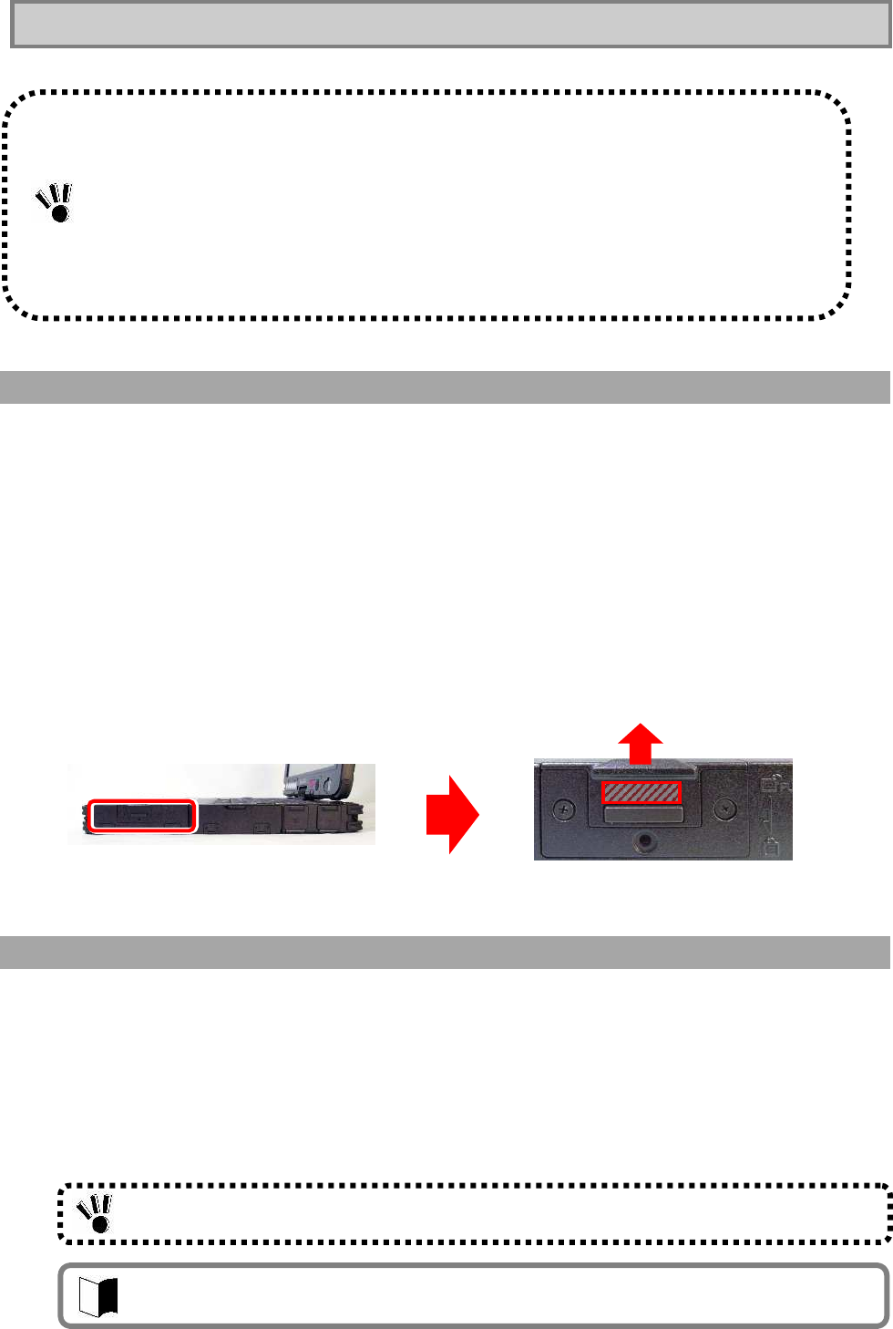
84
2.13.1 Installing/Removing HDD/Silicon Disks
Removal
1 Turn off the power of N22A if operated.
2 Unplug the power cord from the AC outlet and remove the AC adapter from N22A.
When using a car adapter, unplug it from the cigar lighter receptacle and then remove the
car adapter from the N22A.
3 Remove the battery pack from N22A.
See “Replacing Battery” in “Chapter 2 Uses of N22A”for the removal products.
4 Remove the anti-theft screws if they are to be used.
5 While pressing the button of the HDD/silicon disk cover on the right side, slide the
cover upward to open it.
6 Hold the HDD removal support and then pull out the HDD horizontally.
Installation
1 Insert a hard disk/silicon disk assembly into the disk storage area until it is securely
connected.
2 Close the cover, and then press down the part slid to the original position.
3 Attach the anti-theft screws if they are to be used.
4 Install a battery and connect an AC adapter or car adapter.
HDDs are extremely precise equipment. Note the following if used.
During data read/write (with the access lamp being ON), only a small shock may cause the
HDD to be defected.
If the HDD is defected, important data may be unavailable at a time and unable to be restored.
It is recommended to frequently back up important data for which the same data cannot be
created twice.
Depending on models of HDDs, a region with no drive number assigned appears in the [Disk
Management] dialog box. This is the re-setup region required for re-setup. Do not provide the
region with such processing as deletion from targets of disk management.
Put the cover so that the HDD removal support may not be caught.
The HDD/silicon disk cannot be inserted in the wrong direction (upside down). Carefully
check its direction.
85
Security
Chapter 3 Security
3.1
SETTING PASSWORD ON BIOS SETUP UTILITY
You can set a password intended to limit users of starting the system on the BIOS SETUP
Utility.
If you set a password, any user must enter the password for the following operations. This can
increase the security feature:
Starting BIOS SETUP Utility
Starting system
In the BIOS setup menu, the following security passwords can be set.
1. Supervisor password
Users who can start the system are limited. After setting this item, the password
must be entered when starting the BIOS setup menu or the system.
2. User password
Users who can start the system are limited. In addition, the BIOS setup items can
also be limited.
In case users other than the administrator use the N22A, the administrator can
prohibit other users from changing settings.
3. Hard disk password
To prevent illegal use with any device other than the N22A, a password must be
entered when using the HDD by connecting to other devices.
There are two HDD passwords, or HDD master and HDD user passwords.
The HDD master password is intended to release the HDD user password.
The HDD user password is intended to authenticate your computer and the HDD installed in
the computer.
4. I/O LOCK FEATURE
The I/O lock disables the I/O feature, measures to interchange data with external
devices, on the BIOS SETUP Utility.
See “I/O Lock Feature” in “Chapter 4 Setting BIOS”.
For the setting procedure, see “Security setting” in “Chapter 4 Setting BIOS”.
Even if an HDD password has been set, entering the password is not required when
booting your computer.
To use the I/O lock feature, set supervisor and user passwords to limit accessing to the
BIOS SETUP Utility.
86
3.2 LOGIN PASSWORD
The login password is intended to limit users of OS.
If a login password is set, the password must be entered to login to the OS.
<Setting Procedure>
1. Click [Start] [Control Panel].
2. Click [User Accounts] to open the dialog box.
3. Click [Change an account] and click the name of the user for which a login
password is to be created.
4. Click [Create a password] to open the password setting screen.
5. Enter a password in the [Type a new password:] and [Type the new password
again to confirm:] boxes and click [Create password].
3.3 SECURITY CHIP
Setting the security chip allows electronic mails and files to be encrypted and prohibited from
being opened without an authentication password.
In addition, N22A is equipped with a security chip called TPM (Trusted Platform Module) in its
major part to store encryption keys in the security chip. Thus, if only the HDD is withdrawn, the
data in the HDD will not be read.
A login password can be created only by a user having any of accounts in the local
computer including guest and administrator accounts and those created for the computer.
To create a tip for a password, anyone using computers can see the tips on the [Welcome]
screen.
A user having the administrator account of a computer can create or change passwords for
all users of the computer.
A user having a limited account can only create or change his or her own password or
create a tip of the password.
If a user having the administrator account of a computer changes a password of a user,
then the user loses all the passwords stored for EFS encrypted files, personal certificate,
and web site or network resources.
To use the security chip, set supervisor and user passwords to restrict accessing to the
BIOS SETUP Utility.
See “Infineon Security Platform” in “Chapter 5 . Installing OS and Applications ” for details.
87
Security
3.4
FINGERPRINT AUTHENTICATION PASSWORD
(APPLIED TO N22A OF FINGERPRINT SENSOR
INSTALLATION MODEL ONLY)
The fingerprint authentication password is intended to provide authentication by fingerprints
using the built-in fingerprint sensor instead of passwords.
N22A has an attached utility to allow logon to Windows, release of screen saver lock and
substitution for passwords of various applications by fingerprint authentication.
3.5 ANTITHEFT LOCK
A commercial security cable can be used to tie N22A to a desk or so. This is effective to prevent
N22A itself from being stolen.
The antitheft lock hole has the size of 3mm×7mm. Select a security cable fit to the hole.
3.6 ANTITHEFT HDD/Silicon Disk and BATTERY
The attached anti-theft screws are effective to prevent HDD/Silicon disk and the battery from
being stolen.
The cover does not open easily, tighten the anti-theft screws to fix the HDD/Silicon disk cover
and the battery cover.
See “Fingerprint Authentication Utility” in “Chapter 5 . Installing OS and Applications ” for details.
Take sufficient care for management and treatment of important data without overconfidence
of the security cable.
88
Chapter 4 Setting BIOS
This chapter describes the uses of the BIOS SETUP Utility allowing you to set various
environmental conditions on N22A including power management.
4.1 BIOS SETUP UTILITY
N22A has the BIOS SETUP Utility to set the environment in which N22A is used. In initial
booting, the BIOS SETUP Utility is shown in English.
The BIOS SETUP Utility is intended to set an environment of N22A without starting OS.
Using the BIOS Settings on BIOS SETUP UtilitySETUP Utility, you can provide various settings
for security, device, power saving and other features.
4.1.1 Settings on BIOS SETUP Utility
You can perform the following operations on the BIOS SETUP Utility.
(1) Setting the current date and time
(2) Selecting language used on the BIOS SETUP Utility
(3) Checking or changing hardware environment
(4) Setting security
(5) Setting power management
(6) Setting boot of N22A
Any settings changed on the BIOS SETUP Utility will be made effective after rebooting.
If both supervisor and user passwords are set, you cannot make changes on some items on
the BIOS SETUP Utility started with the user password.
If some settings are provided improperly on the BIOS SETUP Utility, N22A does not reboot.
If this occurs, restart the BIOS SETUP Utility to return them to the factory defaults.
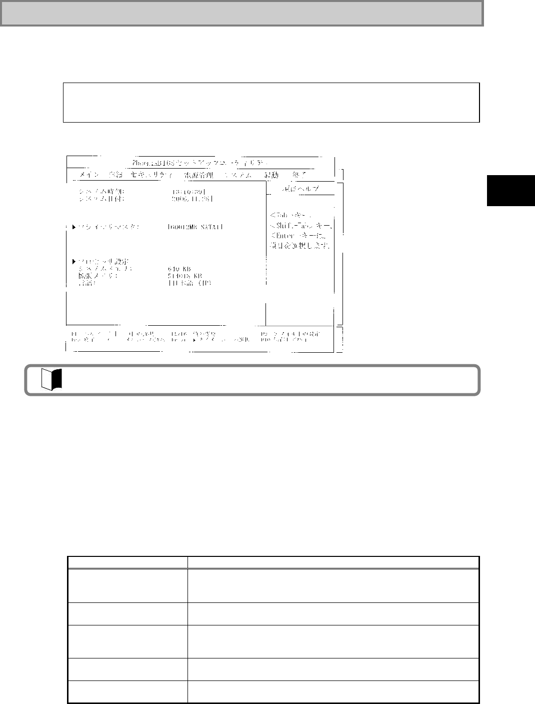
89
Setting BIOS
4.1.2 Running/exiting BIOS SETUP Utility
(1) Starting
If the following message appears on the BIOS start screen appearing after the power of
N22A is turned on, press F2.
The dialog box shown below appears.
(2) Exiting
1. Press F10.
2. The [Setup Confirmation] dialog box appears.
3. Select [Yes] and press Enter.
The setting values are saved and the BIOS SETUP Utility is exited.
Selecting [Exit] on the menu bar can exit the BIOS SETUP Utility.
(3) Exit menu
On the Exit Menu, you can exit the BIOS SETUP Utility or read or save system settings.
Option Description
Exit Saving Changes Saves the setting data resulting from changes and exit the BIOS SETUP
Utility.
(Pressing F10 can do the same exit operation.)
Exit Discarding Changes Exits the BIOS SETUP Utility without saving the setting values
(discarding the current setting values).
Load Setup Defaults Overwrites default values to all setting values.
The default values may be different from factory defaults.
(See the factory defaults.)
Discard Changes Returns the setting values to those before changes.
(The BIOS SETUP Utility remains appearing.)
Save Changes Saves the setting values resulting from changes.
(The BIOS SETUP Utility remains appearing.)
Press <F2> to SETUP or Press <F12> to Network boot.
or
Press <F2> to Enter BIOS SETUP, <F12> to Boot on Network.
The factory default of the language is [English (US)].
Menu bar
Parameter
Key status bar
90
4.1.3 Loading the BIOS SETUP Defaults
The following describes the way to return the data on the BIOS SETUP Utility to their factory
defaults.
1. Turn on the power of N22A.
2. If message “Press <F2> to SETUP or Press <F12> to Network boot.” or “Press
<F2> to Enter BIOS SETUP, <F12> to Boot on Network.” appears on the BIOS
Start screen, press F2.
3. The BIOS SETUP Utility appears.
4. Press F9.
The [Setup Confirmation] dialog box appears.
5. Select [Yes] and press Enter.
The system reads factory defaults.
6. Press F10.
7. Select [Yes] and press Enter.
The system saves the setting values and exits the BIOS SETUP Utility.
Now the job is completed.
The default values may differ from the factory setting values.
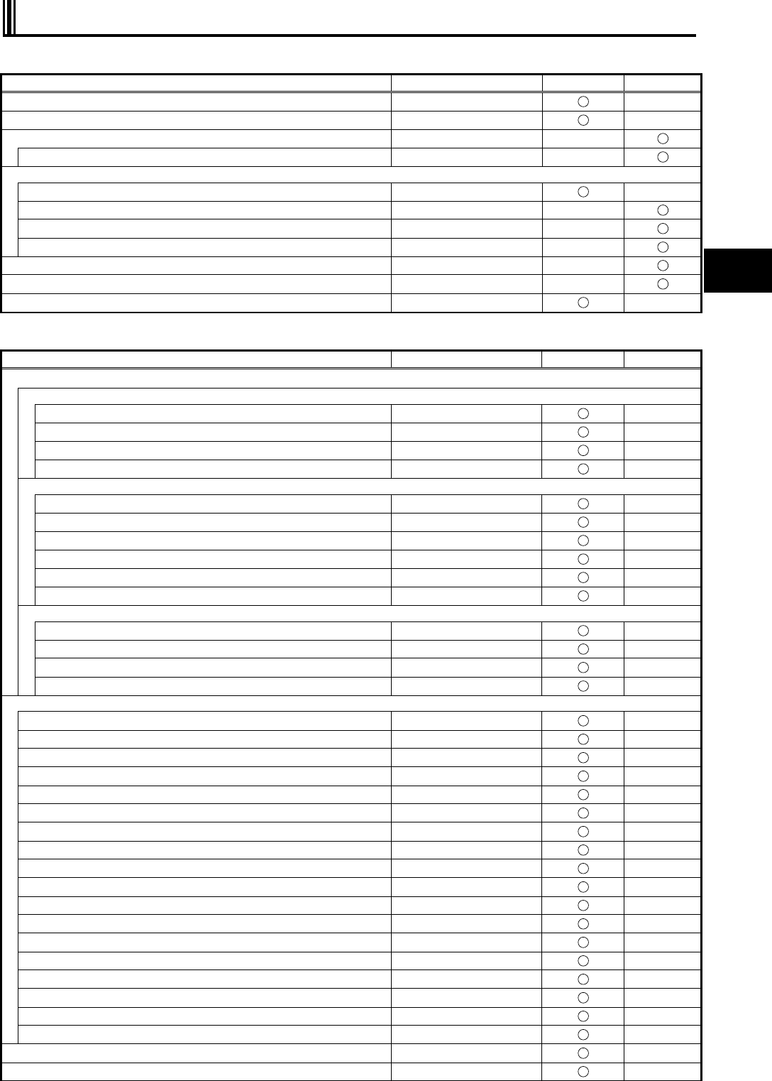
91
Setting BIOS
4.2 LIST OF BIOS SETUP MENUS
(1) Main Menu
Setting Item Factory Default Setting Item
View Only
System Time (Current Time)
System Date (Current Date)
Primary Master (secondary master)
SMART Monitoring Enabled
Processor Settings
CoreMulti-Processing Enabled
CPU Speed ―――
CPU Type ―――
Cache Ram ―――
System Memory ―――
Extended Memory ―――
Language English (US)
(2) Advanced Menu Configuration
Setting Item Factory Default Setting Item
View Only
PCI Configuration
On Board PCI
LAN Controller Enabled
Option ROM Scan Enabled
PCI Express Card Enabled
Wireless LAN Controller Enabled
On Board USB
USB Controller Enabled
USB 2.0 Controller Enabled
Touch Panel Enabled
FingerPrint Sensor Enabled
Bluetooth Controller Enabled
OP Controller Enabled
Card Bus Device
CardBus Controller Enabled
IEEE1394 Controller Enabled
SD Card Slot Enabled
Memory Stick Card Enabled
I/O Device Configuration
Serial port A Enabled
Base I/O address 3F8
Interrupt IRQ 4
Keyboard Enabled
Internal Mouse Enabled
Sound Enabled
Total Graphics Memory 128MB
Display Out LCD+CRT
LCD Panel View Expansion Enabled
LCD Brightness Control Enabled
Illumination Sensor Enabled
LCD Mode Normal
Keyboard Backlight Interlocked
Legacy USB Support Enabled
Parallel ATA Enabled
Serial ATA Enabled *1
Serial ATA Mode AHCI
SMART Device Monitoring Enabled
Reset Configuration Data No
Summary screen Disabled

92
Setting Item Factory Default Setting Item
View Only
Silent Boot Logo screen
QuickBoot Mode Enabled
Fn/Left Ctrl key replacement Disabled
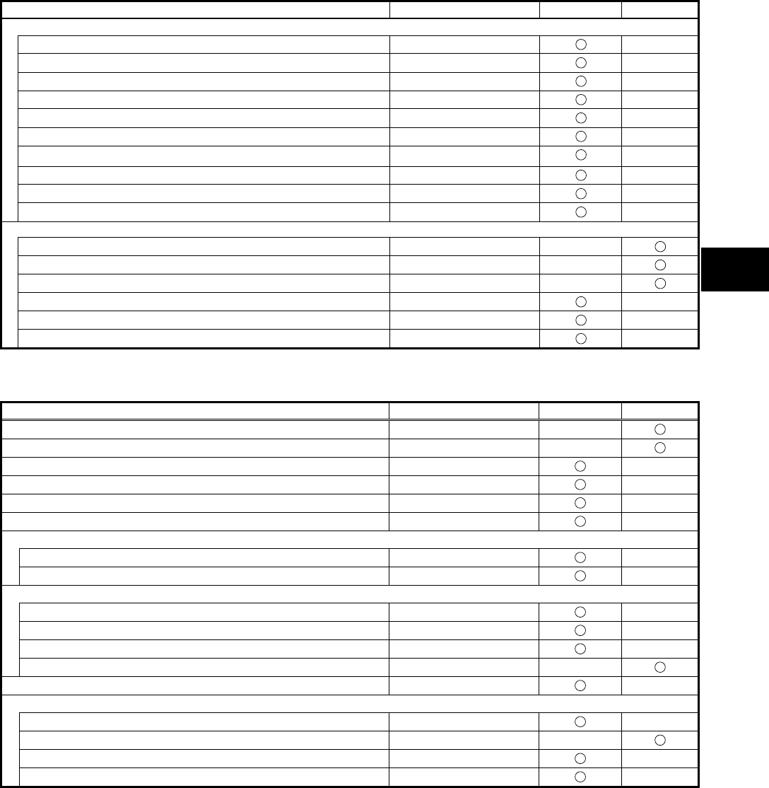
93
Setting BIOS
Setting Item Factory Default Setting Item
View Only
Tablet Button
Tablet Button 1 0h
Tablet Button 2 0h
Tablet Button 3 0h
Tablet Button 4 0h
Tablet Button 5 0h
[Tb] + Tablet Button 1 0h
[Tb] + Tablet Button 2 0h
[Tb] + Tablet Button 3 0h
[Tb] + Tablet Button 4 0h
[Tb] + Tablet Button 5 0h
DMI Event Logging
Event Log Capacity ―――
Event Log Validity ―――
View DMI Event Log ―――
Clear All DMI Event Logs No
Event Logging Enabled
Mark DMI Events As Read ―――
*1: Models with a wide temperature range HDD and silicon disk installed are “Not Used.”
(3) Security
Setting Item Factory Default Setting Item
View Only
Supervisor Password is ―――
User Password is ―――
Set Supervisor Password (No value)
Set User Password (No value)
User Password Protection Disabled
Password on boot Disabled
Network Boot Setting
Keyboard/Mouse Lock Enabled
BIOS LOCK *2 Disabled
HardDisk Security
Fixed disk boot sector Normal
Assign HDD Password (No value)
Secondary Master HDD Password Disabled
Hard Disk Erase ―――
No-Execute Memory Protection Enabled
Security Chip Configuration
TPM support Enabled
Current TPM State *3 ―――
Change TPM State *3 No Change
Password Authentication *3 Disabled
*2: This option appears when the supervisor password is set and [Password on boot] is set to [Enabled].
*3: Not displayed when TPM support is set to “Disabled”.
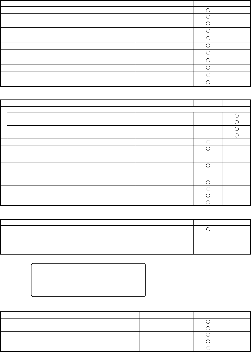
94
(4) Power Management Configuration
Setting Item Factory Default Setting Item
View Only
Power Switch Lock Disabled
Wake On LAN Disabled
Wake On PC Card Disabled
Wake On ExppressCard Disabled
Wake On Ring Disabled
Restore On AC/Power Loss Stay Off
Restore On AC/Power Loss from S4 Disabled
C-States Enabled
CPU Power Level Minimum
Battery Charge Mode Auto
Battery Refresh ―――
(5) System
Setting Item Factory Default Setting Item
View Only
System Management
System Part # FC-N22A
System Serial # ―――
BIOS Revision ―――
EC FW Revision ―――
Temperature Sensor Enabled
Upper Limit 75
Wide Range Temperature
Support: 80
Lower Limit 5
Wide Range Temperature
Support: -25
Voltage Sensor Enabled
POST Errors Enabled
HDD Thermal Sensor Enabled
Self-Diagnostic Program Disabled
(6) Boot Order Configuration
Setting Item Factory Default Setting Item
View Only
This menu lists boot devices in the preference order.
1: USB CD-ROM
2: USB FDC
3: Master HDE
4: Onboard LAN device
(The order shown on the
left)
The actual dialog box appears as follows:
(7) Exit
Setting Item Factory Default Setting Item
View Only
Exit Saving Changes ―――
Exit Discarding Defaults ―――
Load Setup Defaults ―――
Discard Changes ―――
Save Changes ―――
Boot priority order
1: USB CDROM: ---------------------------------------------USB CDROM device
2: USB FDC: --------------------------------------------------USB FDC device
3: IDE HDE: FUJITSU MHW2060BH-(S1) -------------Primary Master HDE
4: PCI LAN: ---------------------------------------------------Onboard LAN device
95
Setting BIOS
4.3 MAIN MENU
(1) System Time
Enter the current time in format “hh:mm:ss” (hh: hour, mm: minute and ss: second)
(2) System Date
Enter the current date in format “yyyy/mm/dd” (yyyy: year, mm: month and dd: date)
(3) Primary Master (Secondary Master)
Indicates the information on devices connected to the primary master (including capacities
and types).
If you move the cursor to this option and press Enter, the relevant setting submenu
appears on the screen.
Select [Advanced] [I/O Device Configuration] [SMART Device Monitoring] to display
the setting information.
If you change some settings, the new information resulting from the change is displayed
after rebooting.
Option Parameter Description
SMART
Monitoring (View only) [Enabled] or [Disabled] appears if the [SMART Monitoring] is
enabled or disabled, respectively.
This setting cannot be changed.
(4) Processor Settings
Indicates the processor information.
If you move the cursor to this option and press Enter, the relevant setting submenu
appears on the screen.
Option Parameter Description Displayed value
Multi-core
mode Disabled
Enabled When set to [Disabled], the CPU operates
in the single core mode.
When set to [Enabled], the CPU operates in
the multiple core mode.
CPU Speed (View only) Indicates the speed of the installed CPU
(by the number of clocks) 1200MHz
CPU Type (View only) Indicates the type of the installed CPU. Genuine Intel(R) CPU
Cache Ram (View only) Indicates the capacity of the second cache
of the installed CPU. 2048KB
* 1
* Shaded value: Factory-set *1 Installation of 256MB memory
(5) System Memory
Indicates the capacity of the system memory.
(6) Extended Memory
Indicates the capacity of the extended memory.
(7) Language
Specify the language used in BIOS. You can select either Japanese or English.
A standard hard disk (80 GB) is displayed as “Primary master”. A wide temperature
range-capable hard disk (40 GB) or silicon disk (20 GB) is displayed as “Secondary master”.
The factory default of the language is [English (US)].
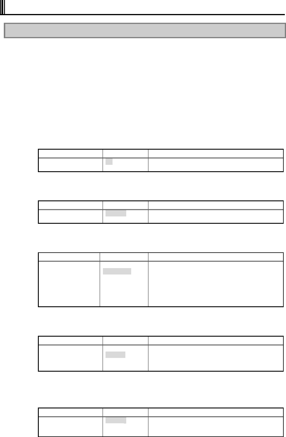
96
4.4 ADVANCED MENU CONFIGURATION
4.4.1 Advanced Menu Configuration
(1) PCI Configuration
This option allows you to provide settings for PCI devices built in N22A.
If you move the cursor to this option and press Enter, the relevant setting submenu
appears on the screen. For the submenu, See “PCI Configuration Submenu” in “Chapter 4
Setting BIOS.”
(2) I/O Device Configuration
This option allows you to provide settings for peripherals built in N22A.
If you move the cursor to this option and press Enter, the relevant setting submenu
appears on the screen. For the submenu, See “PCI Configuration Submenu” in “Chapter 4
Setting BIOS.”
(3) Setting value initialization
This option allows you to initialize the system setting values.
Option Parameter Description
Setting value initialization
No
Yes Set to [Yes] to initialize the resource information.
*Shaded value: Factory-set
(4) Summary screen
The option allows you to specify whether the system setting status is displayed on booting.
Option Parameter Description
Summary screen Disabled
Enabled Set to [Enabled] to display the system setting status on
booting.
*Shaded value: Factory-set
(5) Silent Boot
This option allows you to select the screen displayed on booting.
Option Parameter Description
Silent Boot POST screen
Logo screen
Non screen
Set to [POST screen] to display the Power-On Self-Test
(POST) screen without displaying the NEC logo.
Set to [Logo screen] to display the NEC logo and shorten
the booting time.
Set to [Non screen] to display neither the POST nor NEC
logo screens.
(The booting time is not made shorter.)
*Shaded value: Factory-set
(6) QuickBoot Mode
This option allows you to specify whether a part of tests is skipped on booting or not.
Option Parameter Description
QuickBoot Mode Disabled
Enabled Set to [Disabled] to execute all tests.
Set to [Enabled] to skip a part of tests.
This can shorten the booting time if the extended memory
capacity is considerably large.
*Shaded value: Factory-set
(7) Fn/Left Ctrl key replacement
This option allows the features of Fn and Left Ctrl on the keyboard to be replaced with
each other.
Option Parameter Description
Fn/Left Ctrl key
replacement Disabled
Enabled Set to [Disabled] to operate Fn and Left Ctrl as they are.
Set to [Enabled] to replace the features of Fn and Left
Ctrl of the keyboard to be replaced each other.
*Shaded value: Factory-set
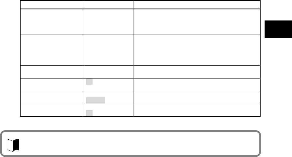
97
Setting BIOS
(8) Tablet Button
This option allows you to assign features to the tablet buttons.
If you move the cursor to this option and press Enter, the relevant setting submenu
appears on the screen.
For the submenu, see “4.3.4 Tablet Button Submenu”.
(9) DMI Event Logging
This option displays the system event log occurring on booting or allows you to set the
system event log.
If you move the cursor to this option and press Enter, the relevant setting submenu
appears on the screen.
Option Parameter Description
Event Log Capacity (View only) If “Space Available” appears, the area where DMI
event log information is stored has empty space.
If “Full” appears, the area where DMI event log
information is stored has no empty space.
Event Log Validity (View only) “Valid” appears normally (normal state).
“Invalid” appears if the event log area becomes illegal
due to power shutdown during storage of event log. If
“Invalid” appears, run [Clear All DMI Event Logs] to
recover the normal state.
View DMI Event Log (View only) Press Enter to display the contents in the DMI event
log entirely.
Clear All DMI Event
Logs No
Yes Select [Yes] to clear the DMI event log entirely after
rebooting.
Event Logging Disabled
Enabled Set to [Disabled] not to record the DMI event log.
Set to [Enabled] to record the DMI event log.
Mark DMI Events As
Read Yes
No Press Enter and select [Yes] to make the currently displayed
log read already.
*Shaded value: Factory-set
DMI (Desktop Management Interface) is a standard specification of hardware-to-software
interface intended to simplify management of each computer for easy system management.

98
4.4.2 PCI Configuration Submenu
The PCI Configuration Submenu allows you to set features of PCI devices built in N22A.
Option Parameter Description
On Board LAN Provide settings for on-board LAN devices.
If you move the cursor to this option and press Enter, the relevant setting
submenu appears on the screen.
LAN Controller Disabled
Enabled Enable or disable wired LAN controller.
Option ROM Scan
PCI Express Card
Wireless LAN
Controller Disabled
Enabled Enable or disable wireless LAN controller.
On Board USB Provides settings for on-board USB devices.
If you move the cursor to this option and press Enter, the relevant setting
submenu appears on the screen.
USB Controller Disabled
Enabled Enable or disable the USB controller.
Set to [Disabled] to disable even the USB2.0
controller. USB connectors become unavailable (I/O
lock).
USB 2.0 Controller Disabled
Enabled Enable or disable the USB2.0 controller.
Set to [Disabled] to disable the USB2.0 controller.
USB devices operate in the USB1.1 specification.
Touch Panel
GPS Controller
FingerPrint Sensor
Bluetooth Controller
Card Bus Device
CardBus Controller
IEEE1394 Controller
SD Card Slot
Memory stick Card
*Shaded value: Factory-set
4.4.3 I/O Device Configuration Submenu
The I/O Device Configuration Submenu allows you to set features of peripherals built in N22A.
Option Parameter Description
Serial port A Disabled
Enabled Set to [Disabled] to disable serial port A (I/O lock) and
release the interrupt.
Set to [Enabled] to enable serial port A.
I/O Base Address 3F8
2F8
3E8
2E8
Specify the I/O base address of serial port A.
Interrupt IRQ 4
IRQ 3 Specify the IRQ of serial port A.
Internal Mouse Disabled
Enabled Set to [Disabled] to disable the touch pad.
Set to [Enabled] to enable the touch pad.
Touch Panel Disabled
Enabled Set to [Disabled] to disable the touch panel.
Set to [Enabled] to enable the touch panel.
Sound / Modem Disabled
Enabled Set to [Disabled] to disable sound (makes the audio
controller disabled).
Set to [Enabled] to enable sound.
Total Graphics Memory
Specify the graphic memory capacity.
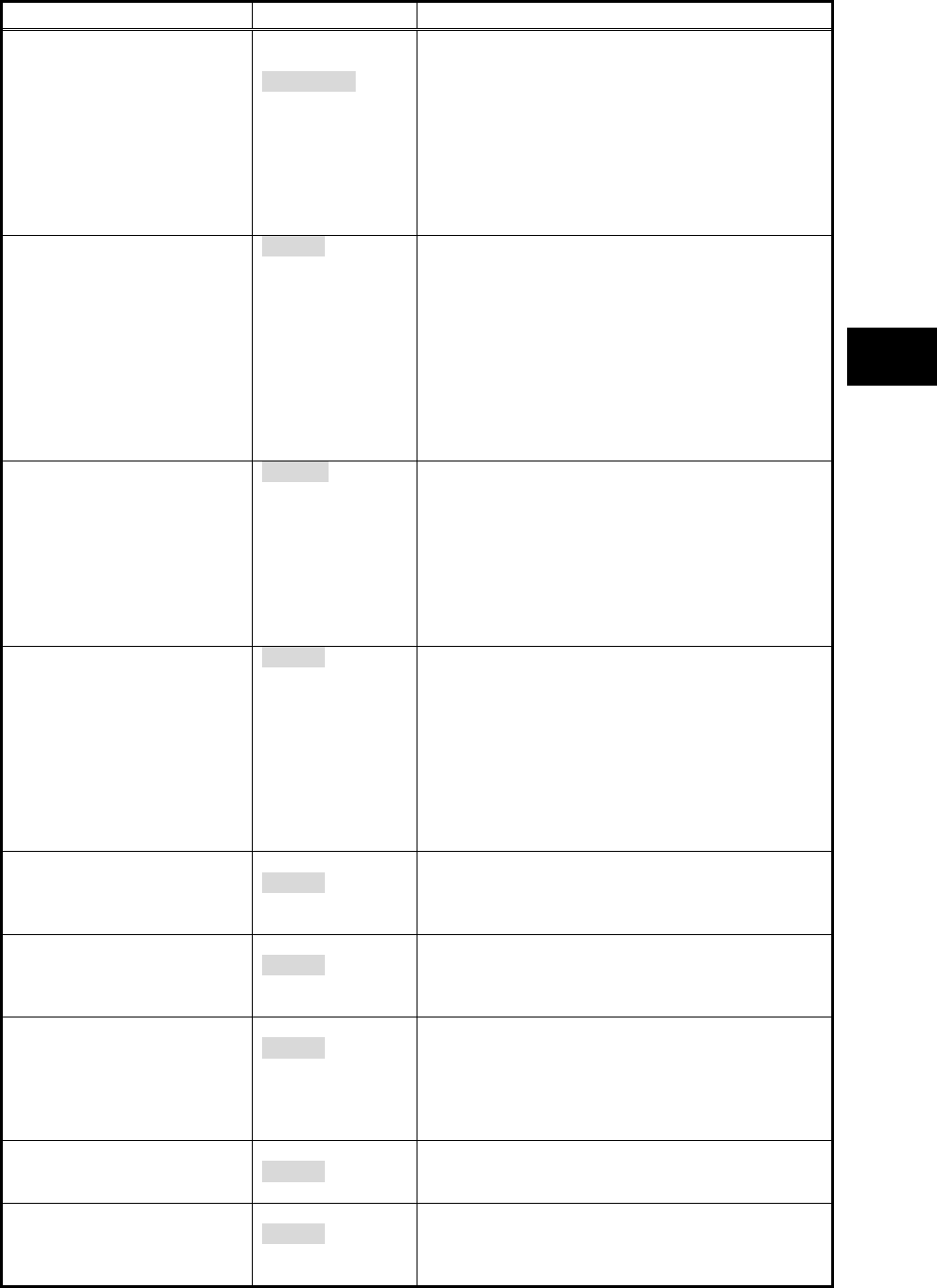
99
Setting BIOS
Option Parameter Description
Display Out CRT
LCD
LCD + CRT
Specify the monitor(s) on which screen data is
displayed.
Set to [CRT] to display screen data on the external
monitor in booting.
(Screen data is not displayed on the built-in LCD
monitor.)
Set to [LCD] to display screen data on the built-in LCD
monitor in booting.
Set to [LCD + CRT] to display screen data on both
monitors in booting.
LCD Panel View Expansion Enabled
Disabled Specify the LCD panel view expansion feature.
If this option is set to [Disabled], a part of area is not
displayed at the top and bottom sides and the left and
right sides on a display screen smaller than the
maximum display size of the LCD panel.
(However, parameter [Disabled] is unavailable if the
screen resolution is set to the maximum value in OS
setting.)
If this option is set to [Enabled], display image smaller
than the maximum display size of the LCD panel is
expanded to be displayed on the full screen.
LCD Brightness Control Disabled
Enabled Specify the LCD brightness control method.
Set to [Disabled] to have the LCD brightness
controlled by OS or driver.
(Tablet buttons 4 and 5 and hot keys Fn + F7, Fn + F8
are disabled to change the LCD brightness.)
Set to [Enabled] to have the LCD brightness controlled
by BIOS. (Tablet buttons 4 and 5 and hot keys Fn +
F7, Fn + F8 are enabled to change the LCD
brightness.)
Keyboard Backlight Connect
Disconnect Specify the keyboard backlight brightness control
method.
Set to [Interlocked] to interlock with the LCD
brightness. The keyboard backlight brightness is
increased/decreased by pressing Fn + F7/Fn + F8.
Keyboard backlight is turned on/off by pressing Fn +
F1.
Set to [Independent] to adjust the keyboard backlight
brightness in 8 levels (dark to bright) or turn on/off it
by pressing Fn + F1.
Legacy USB Support Disabled
Enabled Enable or disable the legacy USB feature.
Set to [Disabled] to disable the legacy USB feature.
Booting from an external USB device is also disabled.
Set to [Enabled] to enable the legacy USB feature.
Parallel ATA Disabled
Enabled Set to [Disabled] to disable the built-in parallel ATA
IDE adapter.
Set to [Enabled] to enable the built-in parallel ATA
IDE adapter.
Serial ATA Disabled
Enabled Set to [Disabled] to disable the built-in serial ATA IDE
adapter.
Set to [Enabled] to enable the built-in serial ATA IDE
adapter.
* For the Linux model with a wide temperature range
HDD, this item is set to [Disabled] at factory.
Serial ATA Mode
Disabled
Enabled Enable or disable the AHCI feature.
Set to [Disabled] to disable the AHCI feature.
Set to [Enabled] to enable the AHCI feature.
SMART Device Monitoring Disabled
Enabled Set to [Disabled] not to provide S.M.A.R.T. monitoring
for IDE devices.
Set to [Enabled] to provide S.M.A.R.T. monitoring for
IDE devices.
* Only for models featuring the function
*Shaded value: Factory-set

100
Option Parameter Description
Reset Configuration Data
Summary Screen
Silent Boot
QuickBoot Mode
Fn/Left Ctrl Key replacement
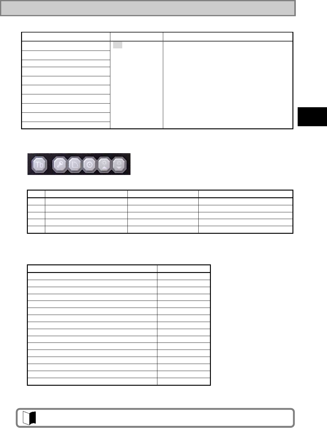
101
Setting BIOS
4.4.4 Tablet Button Submenu
The Tablet Button Submenu allows you to assign features to tablet buttons.
Option Parameter Description
Tablet Button 1
Tablet Button 2
Tablet Button 3
Tablet Button 4
Tablet Button 5
[Tb] + Tablet Button 1
[Tb] + Tablet Button 2
[Tb] + Tablet Button 3
[Tb] + Tablet Button 4
[Tb] + Tablet Button 5
00h
00h ~ FFh
Assign features to tablet buttons.
Enter the key codes to be set.
Key codes shown in the table below are only
available
If [0] is set to an option, the serigraphed standard
feature is enabled for the option.
If [FFFF] is set to an option, the feature of the option
is disabled.
*Shaded value: Factory-set
The table below shows the correspondence between actual tablet buttons and options.
Tb (1) (2) (3) (4) (5)
No
Option Usual feature Feature of [Tb] + [Tablet button]
(1)
Tablet Button 1 Ctrl + Alt + Del ESC
(2)
Tablet Button 2 Screen rotation Tab
(3)
Tablet Button 3 Enter Starting screen keyboard
(4)
Tablet Button 4 LCD brightness UP PgUp
(5)
Tablet Button 5 LCD brightness Down PgDn
The tablet buttons can only have the features listed in the table below. Do not specify any
values other than those in the table below.
Feature Setting value
Ctrl+Alt+Del 0100 h
Screen rotation * E06D h
Enter 005A h
LCD brightness UP 0107 h
LCD brightness Down 0108 h
ESC 0076 h
Tab 000D h
Starting screen keyboard * E06A h
PgUp key 0075 h
PgDn key 0072 h
Keyboard backlight OFF 0101 h
Switching wireless LAN enabled/disabled 0102 h
Switching screen output port 0103 h
LCD backlight OFF 0104 h
FC button 1 * E048 h
FC button 2 * E03A h
* [Screen rotation], [Starting screen keyboard], [FC button 1] and [FC button 2] are enabled only in operation of
Windows
[FC Button 1] and [FC Button 2] can run the execution command (or application starts) registered
on the [FC Button Setup utility] dialog box.
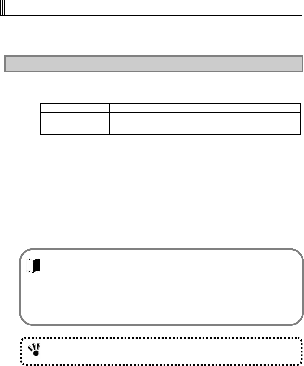
102
4.5 SECURITY MENU
The N22A can limit the BIOS Setup Menu users by setting a supervisor password and user
password, and prevent unauthorized use of the hard disk drive with other than the main unit by
setting a hard disk password.
4.5.1 Security
(1) Supervisor Password
This option indicates whether a supervisor password is set or not.
Option Parameter Description
Supervisor Password is (View only) “Set” appears when a supervisor password is set.
“Clear” appears when a supervisor password is not
set.
(2) User Password
This option indicates whether a user password is set or not.
For the option and description on a user password, see “(1) Supervisor Password” above.
(3) Set Supervisor Password
This option allows you to set a supervisor password. If a supervisor password is set,
accessing to the BIOS SETUP Utility is limited.
<Supervisor password setting procedure>
1. Select [Set Supervisor Password] and press Enter. The setting dialog box appears.
2. Enter a new password in field [Enter New Supervisor Password] and press Enter.
3. Enter the same password in field [Confirm New Supervisor Password] for confirmation and press Enter.
4. When message “Changes have been saved.” appears, press Enter.
The value in field [Supervisor Password is] is changed to [Set].
To change a password already set, enter the current password in field [Enter Current
Password] for confirmation, press Enter and then enter a desired password in the same way
as setting a new password.
A password can only consist of up to eight alphanumeric characters and is not case-sensitive.
If you press Enter without entering anything in the new supervisor password field, both the
supervisor and user passwords are cancelled.
To cancel the user password only, cancel the supervisor password once and then set the
supervisor password only.
Re-setup of N22A cannot cancel the passwords.
Forgetting a password, you cannot cancel the password.
Accordingly, if a password is set, manage it carefully.
103
Setting BIOS
(4) Set User Password
This option allows you to set a user password. If a user password is set, accessing to the
system on booting is limited.
<User password setting procedure>
1. Select [Set User Password] and press Enter. The setting screen appears.
2. Enter a new password in field [Enter New Password] and press Enter.
3. Enter the same password in field [Confirm New Password] for confirmation and press Enter.
4. When message “Changes have been saved.” appears, press Enter.
The value in field [User Password is] is changed to [Set].
(5) User Password Protection
This option indicates whether the user password is protected or not.
Option Parameter Description
User Password Protection
Disabled
Enabled Set to [Enabled] not to allow you to change the user
password if you enter the setup menu with the user
password.
* Shaded value: Factory-set
(6) Password on boot
Option Parameter Description
Password
Disabled
Enabled et to [Disabled] not to request you to enter the user
on boot passwords on booting.
Set to [Enabled] to request you to enter the user
password on booting.
* This option becomes selectable after a supervisor password is set.
Shaded value: Factory-set
Without supervisor password, you cannot select an item to set the user password.
First set the supervisor password.
Entering the BIOS SETUP Utility with the supervisor password, you can check and change
all setting items.
However, entering into it with the user password, you cannot change the following items
(view only).
Items [System Time], [System Date] and [Language] on the [Main] menu
Items [Exit Saving Changes], [Exit Discarding Changes] and [Save Changes] on the
[Exit] menu
Forgetting a password, you cannot cancel the password.
Accordingly, if a password is set, manage it carefully.
104
(7) Network Boot Setting
The option allows you to provide settings on network starting.
If you move the cursor to this option and press Enter, the relevant setting submenu
appears on the screen.
Option Parameter Description
Keyboard/Mouse Lock Disabled
Enabled Allows you to set the operations of the keyboard and
mouse on remote (PME) booting (until OS is
started).
Set to [Disabled] to allow the keyboard and mouse to
be used.
Set to [Enabled] to lock the keyboard and mouse to
be unavailable.
BIOS LOCK Disabled
Enabled Allows you to set [Password on boot] on remote
(PME) booting.
Set to [Disabled] to boot without request of entering
the user password.
Set to [Enabled] to request you to enter the user
password.
This option appears when the supervisor password is
set and [Password on
boot] is set to [Enabled].
*Shaded value: Factory-set
(8) HardDisk Security
This option allows you to set the security of the HDD.
If you move the cursor to this option and press Enter, the relevant setting submenu
appears on the screen.
On the submenu, you can set security features of the HDD as described below.
Option Parameter Description
Fixed disk boot sector Normal
Write Protect Set to [Write Protect] to prohibit data from being
written to the boot sector in the HDD to protect the
sector from virus.
Assign HDD Password (No value) Allows you to set an HDD password.
See Supplement 1: Setting HDD password” for how
to set an HDD password.
Secondary Master HDD
Password Enabled
Disabled Set to [Enabled] to set the HDD password in the
secondary master hard disk drive.
Hard Disk Erase (No value) Erases data in the HDD.
See “Supplement 2: Erasing HDD data” for how to
clear data.
*Shaded value: Factory-set
Supplement 1: Setting HDD password
There are two HDD passwords, or HDD master and HDD user passwords.
<HDD password setting procedure>
1. Select [Assign HDD Password] and press Enter.
2. Enter a supervisor password in field [Enter New Master Password.] and press Enter.
3. Enter the same password in field [Confirm New Master Password.] for confirmation and press Enter.
4. The [Assign HDD User Password] dialog box appears.
5. Enter a supervisor password in field [Enter New User Password] and press Enter.
6. Enter the same password in field [Confirm New User Password] for confirmation and press Enter.
7. Select [Primary Master HDD Password] and press F5 or F6 to set the option to [Enabled].
Remote (PME) booting means that the administrator PC remotely boots a client PC.
Setting a HDD user password can prohibit the HDD from being used in another PC illegally.
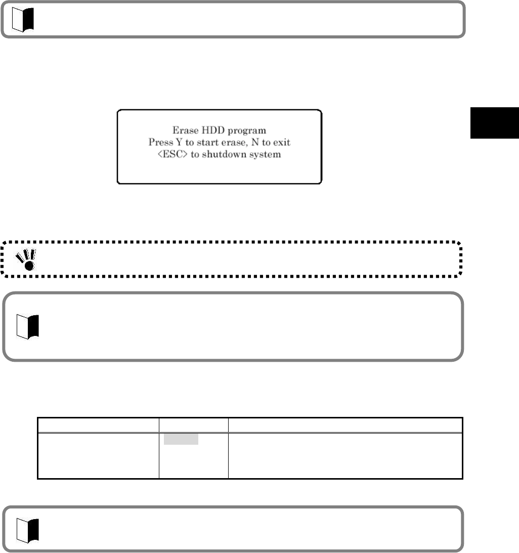
105
Setting BIOS
Supplement 2: Erasing HDD data
The following shows the erase HDD data procedure.
NSA (Random(1) Random(2) 00h)
Writes [random data random data 00] in the order in the entire HDD area.
The erase HDD procedure conforms to the method recommended by NSA.
<HDD erase procedure>
1. Select [Hard Disk Erase] and press Enter. The [Setup Confirmation] dialog box appears.
2. Select [Yes] to exit the BIOS SETUP Utility and transit to the erase HDD dialog box. The following dialog box
appears.
3. Press Y to start erasing the HDD.
Press N to cancel the erase HDD procedure and start system booting.
Press ESC to shutdown the system (power-off).
(9) No-Execute Memory Protection
This option allows you to specify whether the DEP (Data Execution Prevention) feature of
the HDD is enabled or not.
Option Parameter Description
No-Execute Memory
Protection Enabled
Disabled Enable or disable the DEP (Data Execution Protection
Prevention) feature.
Set to [Enabled] to enable the DEP feature.
Set to [Disabled] to disable the DEP feature.
*Shaded value: Factory-set
DEP (Data Execution Prevention) is a feature of preventing illegal programs and data from
being executed in hardware manner. DEP disables computer virus to write or run program
codes illegally.
If you enter the BIOS SETUP Utility with the user password, item [Hard Disk Erase] does
not appear in the menu.
To boot N22A (to start Windows installed in the primary master hard disk), the HDD
master and HDD user passwords being set may not be entered even if [Primary Master
HDD Password] is set to [Enabled].
After the HDD data is erased, the data having been stored in the HDD cannot be restored.
Before erasing the HDD, make sure that necessary data does not remain in the HDD.
Erasure takes 80 to 140 minutes for a standard HDD (80 GB), 25 to 30 hours for a wide
temperature range HDD (80 GB), and 5 to 6 hours for a silicon disk (20 GB).
106
(10) Security Chip Configuration
This option allows you to provide settings for the security chip.
If you move the cursor to this option and press Enter, the relevant setting submenu
appears on the screen.
On the submenu, you can set features of the security chip as described below.
Option Parameter Description
TPM support Disabled
Enabled Enable or disable the security chip called TPM (Trusted Platform
Module).
Set to [Disabled] to disable the security chip (TPM).
Set to [Enabled] to enable the security chip (TPM).
Current TPM State (No setting) Shows the setting status of the security chip (TPM).
(Not displayed when TPM support is set to [Disabled].)
Change TPM State No Change
Enable &
Activate
Deactivate &
Disable
Clear
Enable or disable the security chip (TPM) feature.
Set to [No Change] not to change the security chip (TPM)
status.
Set to [Enable & Activate] to enable the security chip
(TPM) feature.
Set to [Deactivate & Disable] to disable the security chip
(TPM) feature.
Set to [Clear] to return the security chip (TPM) to the
factory setting.
(Not displayed when TPM support is set to [Disabled].)
Password Authentication Disabled
Enabled Enable or disable password lock when setting the security
chip (TPM) feature.
Set to [Disabled] so as not to request entering a password
when setting the security chip (TPM) feature.
Set to [Enabled] to request entering of a password when
setting the security chip (TPM) feature.
*Shaded value: Factory-set
If the security chip is set to Enabled, set supervisor and user passwords to limit accessing to
the BIOS SETUP Utility.
For details on security chips or setting procedure of the utility, see “Infineon Security
Platform” in “Chapter 5 Installing OS and Applications”.
107
Setting BIOS
4.5.2 I/O Lock Feature
The I/O lock disables the I/O feature, measures to interchange data with external devices, on
the BIOS SETUP Utility.
I/O lock can be enabled by setting the following in the BIOS Setup Menu.
(1) How to lock the LAN controller
[Advanced] [PCI Setting] [On Board LAN Device] [LAN Controller] [Do not use]
(2) How to lock the wireless LAN controller
[Advanced] [PCI Setting] [Wireless LAN Device] [Wireless LAN Controller] [Do
not use]
(3) How to lock the USB controller
[Advanced] [PCI Setting] [On Board USB Device] [USB Controller] [Do not use]
(4) How to lock serial port A
[Advanced] [Peripheral Setting] [Serial Port A] [Do not use]
(5) Locking card bus controller (PCMCIA)
[Details] [Peripheral device settings] [Card bus controller] [Disabled]
(6) Locking bluetooth controller
[Details] [Peripheral device settings] [Bluetooth controller] [Disabled]
(7) Locking parallel ATA
[Details] [Peripheral device settings] [Parallel ATA] [Disabled]
(8) Locking serial ATA
[Details] [Peripheral device settings] [Serial ATA] [Disabled]
4.5.3 Clearing BIOS Passwords
N22A can limit users of the BIOS SETUP Utility by supervisor and user passwords and prevent
the HDD from being used illegally by
other computers with HDD passwords.
(1) Clearing passwords by BIOS SETUP Utility
To release passwords, start the BIOS SETUP Utility, enter the existing supervisor
password in [Set Supervisor Password] in the Security Menu and press Enter without
entry of new password.
Forgetting a password, you cannot cancel the password.
Accordingly, if a password is set, manage it carefully.
108
4.6 POWER MANAGEMENT CONFIGURATION
4.6.1 Power Management Configuration
This menu allows you to set power management features.
Option Parameter Description
Power Switch Lock Disabled
Enabled Specify whether the power inhibit release switch is enabled
or disabled.
Set to [Enabled] to enable the power switch with the power
inhibit release
switch being pressed. (Pressing the power switch only
cannot turn on/off the power.)
Wake On LAN Disabled
Enabled Specify whether the power is turned on by the wake on
LAN feature of the internal LAN controller or not.
Wake On PC Card
Wake On ExppressCard
Wake On Ring Disabled
Enabled Specify whether the power of the device connected to the
serial port is turned on or not.
Restore On AC/Power Loss Stay Off
Last State
Power On
Specify the state recovered when the power of the AC
adapter is interrupted and then on again.
Set to [Stay Off] not to turn on the power at AC power-on of
the AC adapter.
Set to [Last State] to return to the state at AC power-off of
the AC adapter. If AC power of the AC adapter is
interrupted with the power being on, the power is turned on.
If AC power of the AC adapter is interrupted with the power
being off, the power is not turned on.
Set to [Power On] to turn on the power at AC power-on of
the AC adapter.
Restore On AC/Power Loss
from S4
Intel SpeedStep(R) technology
Disabled
Enabled Specify whether the Intel SpeedStep technology is enabled
or disabled.
Set to [Disabled] to operate N22A in the battery
optimization performance.
Set to [Enabled] to operate N22A in the performance
optimized by the Intel SpeedStep technology. (The CPU
frequency varies depending on load to CPU.)
C-States Disabled
Enabled Specify the CPU power management status.
Set to [Disabled] to set the CPU power management to C1
status.
Set to [Enabled] to set the CPU power management to C1,
C2, C3, and C4.
CPU Power Level Minimum
Standard
Maximum
Specify the CPU power level when the CPU is entered into
idling state during OS operation.
Set to [Minimum] to transit the CPU to the minimum power
consumption state.
Set to [Standard] to transit the CPU to the normal power
consumption state.
Set to [Maximum] to transit the CPU to the maximum
power consumption state.
Power Mode Disabled
Enabled Specify the power save mode.
Set to [Disabled] to operate the system in the normal mode.
Set to [Enabled] to operate the system in the power save
mode.
109
Setting BIOS
Option Parameter Description
Battery Charge Mode Normal
LongLife
Keeping
Auto
Specify the battery charging mode.
Set to [Normal] to charge the battery fully.
Set to [LongLife] to charge the battery at level of 80%.
(Select this if you want to make the battery life longer.)
Set to [Keeping] to charge the battery at level of 50%.
(Select this if the battery is stored.)
Set to [Auto] to select [Normal] in the normal state but
[LongLife] if the battery temperature becomes higher.
Battery Refresh (No setting) Recovers the battery feature.
Select [Yes] and press Enter to refresh the battery.
*Shaded value: Factory-set
110
4.7 SYSTEM MENU
The System Menu allows you to set system features as described in the table below.
Option Parameter Description
System Management Indicates system information.
If you move the cursor to this option and press Enter,
the relevant setting submenu appears on the screen.
System Part # Indicates the product name of N22A.
System Serial # Indicates the serial number of N22A (not used now).
BIOS Revision Indicates the BIOS revision of N22A.
EC FW Revision
(View only)
Indicates the EC-FW revision of N22A.
Temperature Sensor Disabled
Enabled Specify the temperature monitoring feature.
Set to [Disabled] to disable the temperature monitoring
feature at system booting.
Set to [Enabled] to enable the temperature monitoring
feature at system booting.
Upper Limit [°C] 75
Wide Range
Temperature Support:
80
Indicates the upper limit of the monitoring
temperature.
Lower Limit [°C] 5
Wide Range
Temperature Support:
-25
Indicates the lower limit of the monitoring
temperature.
Voltage Sensor Disabled
Enabled Specify the voltage monitoring feature.
Set to [Disabled] to disable the voltage monitoring
feature at system booting.
Set to [Enabled] to enable the voltage monitoring
feature at system booting.
POST Errors Disabled
Enabled Specify the operation when an error is found during
POST.
Set to [Disabled] to have the system continue booting
if an error is found by the POST.
Set to [Enabled] to suspend booting if an error is found
by the POST and indicate the error content.
HDD Thermal Sensor *1
Disabled
Enabled Specify the HDD temperature monitoring feature.
Set to [Disabled] to disable the HDD temperature
monitoring feature at system booting.
Set to [Enabled] to enable the HDD temperature
monitoring feature at system booting.
Illumination sensor Disabled
Enabled Set the illuminance sensor.
If “Disabled” is selected, the illuminance sensor is
disabled.
If “enabled” is selected, the illuminance sensor is
enabled.
LCD Mode Normal
Enhanced Change the LCD brightness level.
If “Normal” is set, the brightness is changed in the
range from the lowest to level 13.
If “Enhanced” is set, the brightness is changed in the
range from the lowest to level 16.
Self-Diagnostic Program
*Shaded value: Factory-set
*1: For wide temperature range HDD, “HDD Temperature Sensor” is not displayed.
Operations when temperature sensor is set to “Use”
Monitor system temperature (internal temperature sensor) at power on (BIOS startup),
where an error message will appear, after BIOS startup is completed, if the temperature
is outside the range between upper and lower limits of the setting values.
The temperature sensor has a margin of error. In case of operating at temperatures
close to the lower limit of monitoring temperature, adjust the setting value if an error
message appears after BIOS startup is completed.
Do not change “Upper Limit of Monitoring Temperature” to a greater value since the main
unit internal temperature will rise after power is turned on.
This operation is performed only on startup, and will not be performed after the operating
system starts.
111
Setting BIOS
4.8 BOOT MENU
4.8.1 Boot Order Configuration
This menu lists boot devices in the preference order. The top device first tries to start the OS. If
the device cannot start the OS due to such a reason as no existence of OS,
the next device tries to start the OS.
To change the boot device, press PgUp or PgDn to move the cursor to the device to be used to
start the OS.
Press F5 or F6 to move the cursor upward or downward in the list, respectively.
Press x to move the cursor in [Boot priority order] and [Excluded from boot order].
Up to eight devices can be registered in [Boot priority order].
The factory set priority is defined as follows:
1: USB CD-ROM
2: USB FDC
3: Master HDE
4: Onboard LAN device
The actual dialog box appears as follows:
Boot priority order
1: USB CDROM: --------------------------------------------------------------USB CDROM device
2: USB FDC:--------------------------------------------------------------------USB FDC device
3: IDE HDE: FUJITSU MHW2060BH-(S1) ------------------------------Primary Master HDE
4: PCI LAN: --------------------------------------------------------------------Onboard LAN device
5:
6:
7:
8:
Excluded from boot order
: USB KEY: ------------------------------------------------------------------USB KEY device
: USB HDD: -----------------------------------------------------------------USB HDD device
112
Chapter 5 Installing OS and Applications
5.1 WINDOWS XP PRE-INSTALLED MODEL
5.1.1 Configuration of Windows XP Pre-installed Model
N22A of Windows XP pre-installed model has Microsoft Windows XP Professional installed at
factory shipment to be automatically booted at power-on.
The parameters are previously set to the factory defaults as shown in the table below.
Accordingly, you may not enter them on booting of N22A.
Parameter Factory default
Owner FC-USER
Organization (Not set)
Computer name FC-N22A-XXXXX
Value “XXXXX” in the computer name shows the lowest five digits of the product ID of Microsoft Windows XP
Professional.
For the product ID, see the Microsoft Windows XP Professional license label pasted on the bottom of N22A.
For how to change the computer name, see “Specify computer and workgroup names” in the Online Help of
Microsoft Windows XP Professional.
To change the owner or organization, see next subsection “Changing Owner and/or Organization by Modifying
Registry” or provide re-setup for Windows XP. For the re-setup, see “Chapter 6 Re-setup of Windows XP in
N22A of Pre-installed Model”.
For the HDD installed in N22A of pre-installed model, the first and second partitions (or system and remaining
areas respectively) are formatted at shipment from factory.
To change the format so as to assign the second partition (remaining area) to more than one drive, select [Start]
[Control Panel] [Performance and Maintenance] [Administrative Tools] [Computer Management]
[Disk Management] after the setup is completed.
Standard HDD (80 GB) or wide temperature range HDD (40 GB):
Capacity (1st HDD)
First partition Second partition
20GB (NTFS) Standard HDD: About 40GB (NTFS)
Wide temperature range HDD: About 20GB (NTFS)
Silicon disk (20GB)
Capacity (1st HDD)
First partition Second partition
113
Installing OS and Applications
Changing Owner and/or Organization by Modifying Registry
Note that Windows XP installed in N22A is not specified as an upgrading/downgrading
product by Microsoft.
The following warning may be recorded in the event log at the time of log-off, this is only an
indication and the operation of OS is not affected.
Event ID : 1517
Source : Userenv
Type : Warning
Description : Windows saved the user’s registry at log-off though the application or the
service is using the registry. The memory used by the user’s registry has
not been released.
The registry will be unloaded when it is not used.
This is due to execution of the service as a user account.
Try to configure the service with LocalService or NetworkService.
Although the following warning/error may be recorded to the Event Viewer event log when
returning from the standby state, this is only a display problem and the OS is functioning
normally.
Event ID : 256
Source : PlugPlayManager
Type : Warning
Description : Transmission for reporting the change of device interface to “IWMSWindow”
window times out.
Event ID : 7011
Source : Service Control Manager
Type : Error
Description : A timeout occurred during wait for transaction response from the WZCSVC
service.
The registry has a variety of information required to operate Windows XP.
Changing the registry incorrectly may cause Windows XP to be started improperly. Change
the registry with sufficient care.
If Windows XP is not started or started improperly after change of the registry, reinstall
Windows XP.
Be sure to change the registry before installing applications in N22A. If the registry is changed
after some applications are installed, the changed registry may not be reflected on the
versions of the applications.
However, Windows XP can operate normally.
Only symptoms such as shown by an example below may appear:
Ex: When organization and/or owner are changed after Microsoft Excel is installed,
Selecting [Control Panel] [Organization/owner in System] causes the organization
and owner after registry change to be displayed.
The version information in the Help file of Excel indicates the organization and owner
after registry change.
* The operation is not affected.
114
(1) Registry change procedure
1. Start WindowsXP.
2. Click [Start] [Run…], type “c:¥windows¥regedit.exe”, and click [OK].
3. Open HKEY_LOCAL_MACHINE¥SOFTWARE¥Microsoft¥Windows NT¥CurrentVersion.
4. Click the following items and change the organization and/or owner.
Registered Organization
Registered Owner
5. Click [File] [Exit] to exit the registry editor.
(2) Organization/owner check procedure
1. Start Windows XP.
2. Right-click [My Computer] and click [Property].
Microsoft Windows XP Professional License Label (COA label)
N22A of pre-installed mode has Last Known Good Configuration Microsoft Windows XP
Professional license label (COA label) pasted on the bottom of N22A.
The label includes some important information including “Product ID”. Take sufficient care
on that label so that the label may not be damaged, broken or peeled off.
5.1.2 “Microsoft Windows XP Service Pack 2”
The OS installed in N22A of Windows XP pre-installed model is “Microsoft Windows XP Service
Pack 2” (called Service Pack 2 below).
Service Pack 2 includes a set of update programs intended to improve or correct faults and
problems found after the first supply of Windows XP.
Addition/deletion
Do not delete Service Pack 2 from N22A.
Some device drivers are only applicable to Service Pack 2. Thus, deleting Service Pack 2
may cause some drivers to be operated improperly.
The latest and other information on Windows XP is provided on the following web site. Access
the site periodically.
http://www.microsoft.com/japan/windowsxp/downloads/
The Microsoft Windows XP Professional license label (COA label) shall not be re-issued if it is
damaged, broken or peeled off.
Note: Because the COA label is partially transparent and not laminated, it seems to get a hole
or be broken.
However, it does not indicate that the label is damaged. The transparent part of the label
may have a unique shape due to special processing to be different from others.
115
Installing OS and Applications
5.2 INSTALLING ATTACHED APPLICATIONS
5.2.1 Standby Rescue Lite
(1) Overview
A full copy of the boot area (referred as Active Area hereafter) currently running is made to
the “standby area” in the same volume, and the system will quickly switch to the
failure-free system by restarting the system when a failure occurred.
The main features are as follows:
1. Copying/Updating
Create a full backup of the Active Area in the standby area.
2. Rescue start
When a failure occurs, the system can start with the failure-free area by quickly
switching (rescue start) from the Active Area to the standby area automatically or
manually.
3. File Exclusion Feature
Register files not to be backed up in the standby area, such as temporary files and
specific files/folders, to the exclusion list in order to reduce the standby area size.
4. Setting Password
Protect “Display Option Dialog”, “Copying/Updating”, and “Rescue start now”
execution by setting a password.
Be sure to log in as a user having an Administrator privilege, to add or remove
applications.
An administrator privilege is a privilege to manage the entire configuration of a computer.
If you are unsure how to log in as a user with an administrator privilege, on the [Logon
information] screen, enter “Administrator” in the [User name] field and, in the [Password]
field, a password that you set for an administrator account when you started this machine
for the first time. Select the computer name that you set when you started this machine
for the first time and click the [OK] button. A domain name is shown only when a domain
has been set for network installation.
Installation software is stored in drive C (hard disk), so a CD-ROM drive unit is not
required during installation.
Applications do not come with the English version preinstalled model and the Linux
preinstalled model.
CD-ROM/DVD drive unit is not required because “Set of Installation Software” is stored on
Drive C (hard disk).
This software is not included with Linux Pre-installation models.
Since the standby area requires the same space size as the space used by Active Area,
there must be unused space at the same size or larger than the currently used space in the
system drive.
Drives other than the system drive cannot be backed up.
This software cannot be used for Silicon Disk models.

116
(2) Supported Operating Systems
Microsoft® Windows® XP Japanese Version (SP2)
Microsoft® Windows® XP English Version (SP2)
(3) How to Install
1. Start Windows.
2. Click [Start] [Control Panel].
3. Double click [Add/Remove Programs].
4. Click the [CD or Floppy Disk (F)] button in the [Add Program] tab.
5. Click the [Next] button in the [Install from Floppy Disk or CD-ROM] window.
6. Enter [C:¥WINXP¥SRL300¥setup.exe], then click the [Finish] button.
7. Follow the instructions displayed in the window to install.
Restart the computer.
The installation of Standby Rescue Lite is completed.
(4) How to start
Click [Start] [Programs] [Standby Rescue Lite] [Standby Rescue Lite].
If copying/updating to the standby area has not been performed, a confirmation message
for standby area creation will appear.
The main window of Standby Rescue Lite will appear when copying/updating is completed.
(5) How to delete
1. Start Windows.
2. Click [Start] [Control Panel].
3. Double click [Add/Remove Programs].
4. Click the [Standby Rescue Lite], then click the [Change/Remove] button.
5. Click the [Yes] button when the [Confirm File Delete] window appears.
6. Click the [No to All] button when [Delete Shared File] appears.
7. Click the [OK] button when [Uninstall Complete] appears.
Restart the computer.
Standby Rescue Lite deletion is completed.
(6) Details
For details on features and operations
Please refer to “SRL_UserGuide.pdf” stored in C:¥WINXP¥SRL300¥Docs¥.
Cautions and Restrictions
Refer to “Readme.txt” stored in “C:¥WINXP¥SRL300¥”.
Latest information on “Standby Rescue Lite”
Visit NetJapan’s Website at http://www.netjapan.co.jp/ (Japanese only).
Install Adobe
®
Reader
®
to view SRL_UserGuide.pdf.
117
Installing OS and Applications
5.2.2 Software RAS Tool
(1) Overview
This tool monitors hardware status and SMART information of the hard disk, and records
in log files, outputs to Windows Event Viewer, and starts specified programs when an
abnormality causing failures is detected.
Main features are as follows:
1. Hardware status monitoring feature
Monitors hardware status such as the internal temperature, fan, voltage, PCI parity,
and mirroring interface board. Also, monitors the SMART (Self-Monitoring Analysis
and Reporting Technology) information of the hard disk (hard disk built-in
self-diagnosis feature).
2. Logging/abnormality output features
Regularly monitors the hardware status, and saves (logging) to a file.
Also, outputs to Event Viewer or starts specified programs when an abnormality is
detected.
3. Failure analysis feature
Supports failure analysis with the following features.
In the file saved by the logging feature, monitored time (Windows calendar time and BIOS
calendar time) is also recorded.
Outputs error information, by converting from a memory dump file output when a Windows
system error occurs, to a text file.
4. Power switch feature
For Windows® XP/Server® 2003, Windows menu shutdown and power switch
shutdown are the same operations; however, the power switch shutdown for
Windows® 2000 does not save data.
With this feature, the same operations as Windows menu shutdown can be
performed for Windows® 2000 when shutting down with the power switch.
5. Calendar correction feature
Sets the BIOS calendar time to Windows calendar time.
6. Digital input/output feature
Digital data input/output can be performed with RAS library features.
(2) Supported Operating Systems
Microsoft® Windows® XP Japanese Version (SP2)
Microsoft® Windows® XP English Version (SP2)
(3) Details
These features are available by installing the attached “Software RAS”.
For using these features and details, change settings by referring to the “Software RAS”
PDF file.
CD-ROM/DVD drive unit is not required because the “Set of Installation Software” is stored
on Drive C (hard disk).
Windows Vista
®
is not supported.
Software RAS tool is not installed at factory default.
To use this tool, install Software RAS tool following the instructions in the PDF file stored in
C:¥WINXP¥SoftRAS¥.
118
5.2.3 Adobe® Reader® 7.0
(1) Overview
Display, view, and print electrical manuals in PDF (Portable Document Format) format.
When using Adobe® Reader® 7.0 for the first time after installation, the “Software
License Agreement” window will appear. Click the [I agree] button.
When adding or removing application software, make sure to log in as a user with
Administrator right.
When adding another application after setting up again, make sure to restart Windows
before adding another application.
Read [Start] [Programs] [Supplemental] before adding or removing application
software.
(2) How to Install
1. Start Windows.
2. Insert the included “Recovery DVD-ROM Media” into the CD-ROM/DVD drive.
3. Click [Start] [Run].
4. For Japanese version: Enter
“C:¥WINXP¥AdbeRdr¥JPN¥AdbeRdr70_jpn_full.exe” for [Name], then click the
[OK] button.
For English version: Enter
“C:¥WINXP¥AdbeRdr¥ENU¥AdbeRdr70_enu_full.exe” for [Name], then click
the [OK] button.
5. Click the [Next] button when the [Adobe Reader 7.0 Setup] window appears.
6. Click the [Next] button when the [Welcome to Adobe Reader 7.0-Japanese
Setup] window appears.
7. Click the [Next] button when the [Destination Folder] window appears.
To change the installation destination folder, click the [Change Destination
Folder...] button, select the folder to install from the [Look in:] window, then
click the [OK] button.
8. Click the [Install] button when the [Ready to Install the Program] window
appears.
9. Click the [Finish] button when the [Setup Completed] window appears.
The installation of Adobe® Reader® 7.0 is completed.
CD-ROM/DVD drive unit is not required because “Set of Installation Software” is stored on
Drive C (hard disk).
This software is not included with Linux Pre-installation models.
Adobe
®
Reader
®
7.0 is not installed at factory default. To use, install Adobe
®
Reader
®
7.0 by
referring to “How to install” below.
An Administrator right is the right of administrators to mange the entire computer
configuration. If you are not sure how to log in as a user with Administrator right, in the
[Logon Information] window, enter “Administrator” for the username, enter the Administrator
account password set when the computer started for the first time for [Password], and select
the computer name set when the computer started for the first time for [Domain Name], then
click the [OK] button. The domain name is displayed only when the domain was set for
network installation.
119
Installing OS and Applications
(3) How to start
Click [Start] [Programs] [Adobe Reader 7.0].
Adobe® Reader® 7.0 window appears.
(4) How to delete
1. Start Windows.
2. For Windows® XP: Click [Start] [Control Panel].
3. For Windows® XP: Double-click [Add/Remove Programs].
4. Click “Adobe Reader 7.0” then click the [Remove] button.
5. Click the [Yes] button when the [Confirm File Delete] window appears.
6. Click the [No to All] button when the message “Delete Shared File?” appears.
7. For Windows® XP: Click the [Yes] button to restart the computer when a
window prompting to restart the computer appears.
Adobe® Reader® 7.0 deletion is completed.
5.2.4 Fingerprint authentication utility (only models with this feature)
Fingerprint authentication is a system that authenticates a user according to fingerprint by use
of a fingerprint sensor. The fingerprint authentication allows the following features to be
executed:
To logon Windows and cancel the lock of screen saver
A replacement password for an application (Protection of the important files)
(1) Supporting OSs
Microsoft Windows XP, English Ver. (SP2)
(2) Installation procedure
1. Start Windows.
2. Click [Start] [Control Panel].
3. Double-click [Add or Remove Programs].
4. Click [CD or Floppy] on the [Add new Programs] tab.
5. If message “Install Program From Floppy Disk or CD-ROM, and then click
Next.” appears, click [Next].
6. Click [Browse…] and change the file type to [Program].
Specify “C:¥WINXP¥Fingerprint Sensor¥autorun.exe” and click [Open].
7. The menu window appears. Click [Software Installation].
8. Follow the directions on the window. For details of installation, see
“C:¥WINXP¥FingerprintSensor¥doc¥0411¥Manual.pdf”.
9. After the installation is completed, reboot N22A.
Now the Fingerprint Authentication Utility is completely installed.
This function does not come with Linux preinstalled models.
For how to register fingerprints and how to use, refer to the following document.
“Click C:¥WINXP¥Fingerprint Sensor¥autorun.exe and browse Manual.pdf.”
To browse the documentation file, Acrobat Reader 7.0 must be installed.

120
(3) Usage
1. Start Windows.
2. Click [Start] [Settings] [Control Panel].
3. Double-click [Add or Remove Program].
4. Click [CD or Floppy] on the [Add new Programs] tab.
5. If message “Install Program From Floppy Disk or CD-ROM, and then click
Next.” appears, click [Next].
6. Click [Browse…], specify “C:¥WINXP¥Fingerprint Sensor¥autorun.exe” and
click [OK].
7. The menu dialog box appears. Click [Documentation].
Open “Manual.pdf” to check usages including the fingerprint registration procedure.
(4) Deletion procedure
1. Start Windows.
2. Click [Start] [Settings] [Control Panel].
3. Double-click [Add or Remove Program].
4. Click [Protector Suite QL] and [Change].
5. Follow the directions on the dialog box to uninstall the fingerprint
authentication utility.
6. After the uninstallation is completed, reboot N22A.
Now the fingerprint authentication utility is removed completely.
Data saved in the biometric device (chip for fingerprint sensor) is not erased even if the built-in
HDD is erased.
See “C:¥WINXP¥Fingerprint Sensor¥doc¥0411¥Manual.pdf” to uninstall the fingerprint
authentication utility in the proper procedure.
121
Installing OS and Applications
5.2.5 Infineon Security Platform
Using Infineon Security Platform allows electronic mails and files to be encrypted and
prohibited from being opened without authentication password.
In addition, N22A is equipped with a security chip called TPM (Trusted Platform Module) in its
major part to store encryption keys in the security chip. Thus, if only the HDD is withdrawn, the
data in the HDD will not be read.
(1) Supporting OSs
Microsoft Windows XP, English Ver. (SP2)
(2) BIOS setting procedure
Set BIOS in the following procedure.
1. After power-on of N22A, the BIOS start screen (with NEC logo displayed at the
center) appears. If message “Press <F2> to SETUP or Press <F12> to Network
boot.” appears, press F2.
2. After the BIOS SETUP Utility menu appears, select [Security].
3. Select [Security Chip Configuration] and press Enter.
4. Select [Security Chip] and press Enter.
5. Select [Enabled] and press Enter.
6. Item [Security Platform] appears. Select it and press Enter.
7. Select [Enabled] and press Enter.
8. Press F10 to open the [Save configuration changes and exit now?] dialog box.
Select [Yes] and press Enter. An attempt is made to restart BIOS.
9. After restarting, the [Physical Presence Operations] dialog box is opened.
10. Select [Execute] and press Enter to try to restart BIOS.
For details of the features, operations and restrictions of the Infineon Security Platform, see
“C:¥WINXP¥TPM¥Readme¥JP¥Readme.txt”.
To use the security chip, set supervisor and user passwords to restrict accessing to the BIOS
SETUP Utility. See “SECURITY MENU” in “Chapter 4 Setting BIOS”.
122
(3) Installation procedure
1. Start Windows.
2. Click [Start] [Settings] [Control Panel].
3. Double-click [Add or Remove Program].
4. Click [CD or Floppy] on the [Add new Programs] tab.
5. If message “Install Program From Floppy Disk or CD-ROM, and then click
Next.” appears, click [Next].
6. Click [Browse…], specify “C:¥WINXP¥TPM¥Setup.exe” and click [OK].
7. If [Infineon TPM Integration SDK- InstallShield Wizard] appears, click [Next].
8. Install the Infineon Security Platform according to the directions on the screen.
9. If the installation is completed and the message prompting you to reboot N22A,
click [Yes] to reboot it.
Now the Infineon Security Platform is installed completely.
(4) Starting procedure
The [TPM] icon appears on the task tray at the bottom right corner of the screen. Click the
icon to display its menu.
(5) Deletion procedure
1. Start Windows.
2. Click [Start] [Control Panel].
3. Double-click [Add or Remove Programs].
4. Click [Infineon TPM Professional Package] and [Change/Remove].
5. If the [Confirm File Deletion] dialog box appears, click [Yes].
6. When [Delete shared file?] appears, click [No to all].
7. After the uninstallation is completed, reboot N22A.
Now the Infineon Security Platform is deleted completely.
After the installation, select [Security Platform Initialization] and [Security Platform User’s
Initialization] on the menu displayed by selecting the TPM icon.
Then select [Manage Security Platform] to set security features.
Just after BIOS setting, the hardware add wizard requests driver installation. However, the
driver can be installed in the following procedure. you may cancel the hardware add wizard.
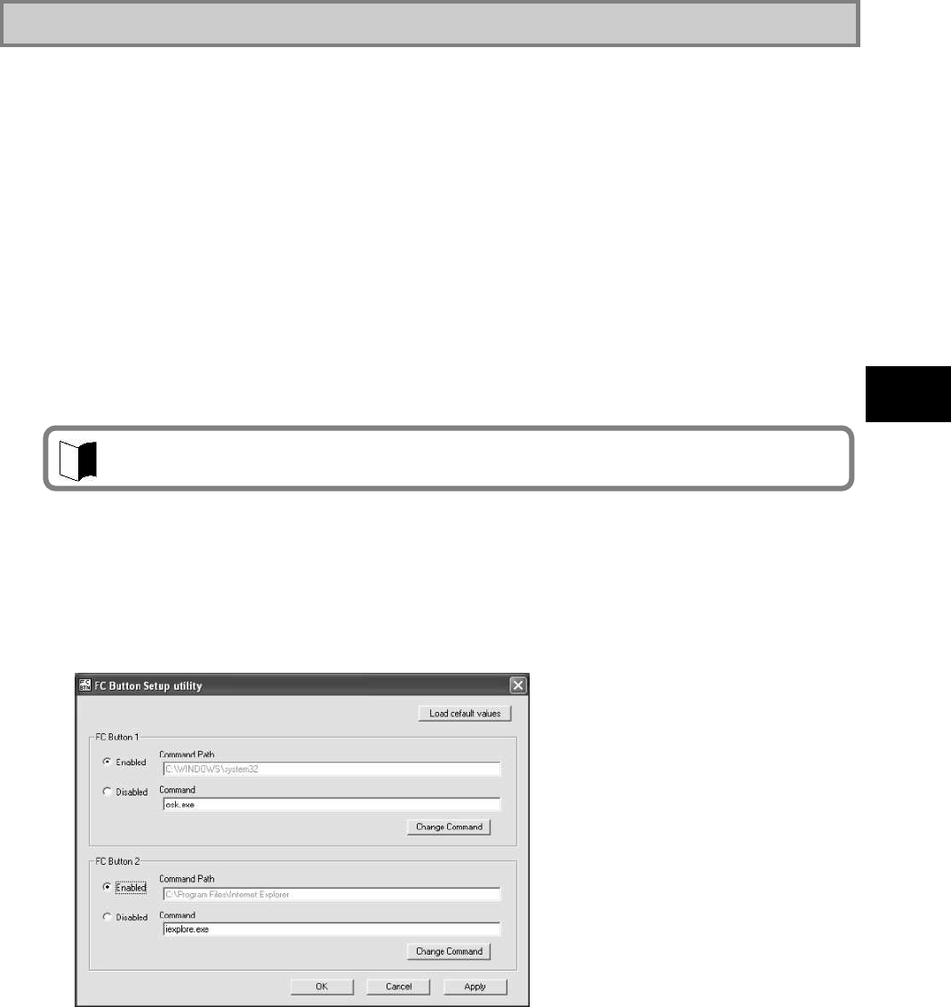
123
Installing OS and Applications
5.2.6 FC Button Setting Tool
Two sets for executing desired applications can be registered to abbreviation keys.
(1) Supporting OSs
Microsoft Windows XP, English Ver. (SP2)
(2) Usage
The registered applications can be executed by Fn+1 (FC button 1) and Fn+2 (FC button
2), respectively.
The tablet buttons at the lower left corner of the LCD display can be assigned new features
different from their original ones by using the BIOS SETUP Utility.
If any of the keys are assigned [FC button 1] and/or [FC button 2], the execution
commands (or application starts) registered on the [FC Button Setup utility] dialog box can
be run.
FC button 1 and FC button 2 must be assigned to tablet buttons via the BIOS setup menu
to use the above function.
See C:¥WINXP¥FCBTN¥FCbtnReadme.txt for details.
(3) Start procedure
Click [Start] [All Programs] [FC Button Setup utility].
The [FC Button Setup utility] dialog box shown below appears. Set the buttons
appropriately.
For BIOS settings, see “Chapter 4 Tablet Button Submenu”.

124
5.3 OTHER OSS AND APPLICATIONS
(1) CD-R/RW with DVD-ROM drive
Option FC-CW002U (external CD-R/RW with DVD-ROM drive) contains writing tool. A
DVD video replay tool is commercially available.
(2) English version preinstalled model
The procedure for re-setup using the accompanying recovery DVD-ROMs is the same as
that for the Japanese version. Refer to CHAPTER RE-SETUP of Windows® XP
PREINSTALLED MODEL.
The accompanying recovery DVD-ROMs for the English version preinstalled model comes
as one DVD-ROM.
(The accompanying recovery DVD-ROMs for the Japanese version preinstalled model
comes as one DVD-ROM.
Among the applications accompanying this product, the following can be used with English
preinstalled models.
<Applications that can be used in the English version>
Fingerprint authentication utility
FC button setting tool
Adobe Reader7.0
Standby Rescue Lite
Infineon Security Platform
Software RAS Tool

125
Installing OS and Applications
THIS PAGE INTENTIONALLY LEFT BLANK.
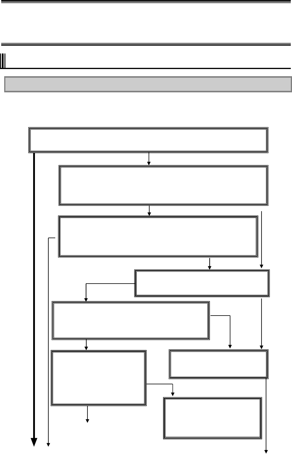
126
Chapter 6 Maintenance
6.1 TROUBLESHOOTING
6.1.1 Flowchart
This section describes many solutions to troubles. If a trouble occurs, see the section to find
the solution to the trouble according to the procedure below.
If a trouble occurs, first refer to the guide.
Check peripheral devices.
To check if a peripheral device is
available to
N22A, refer to the User’s Guide or
ask your sales agent or manufacturer.
Is N22A booted normally?
If the NEC Logo screen does not appear (excluding the case where BIOS is set not to
display the NEC Logo screen) or message “Operating system not found” appears in
N22A booting, a hardware error may occur.
No
If smoke, odor or noise is generated, turn off the power immediately and pull out the plug of the
power cord from AC outlet. (If a car adapter is used, remove the plug from the cigar lighter
receptacle and remove the car adapter from this product.)
Take actions.
Take action according to the relevant
event in “Troubleshooting Q&A.”
Booted normally
Not booted
No applicable
No tips found
Not soluble
Remove peripheral devices.
If the troubles cannot be solved still,
turn off the power.
Remove added peripheral devices
(including expanded board, memory
and hard disk) and check if N22A
operates normally.
Check hints.
If applicable actions are not found or some measures cannot
resolve the symptom, see “Actions Taken to Solve Trouble
(Tips).” The section describes tips to solve troubles.
Search for applicable information.
No applicable Search “Troubleshooting Q&A”
for the situation in which a trouble occurs.
Booted
Boot N22A in safe mode.
If N22A is not booted normally, boot it in the safe mode to check the status and/or
change some settings.
For how to boot N22A in the safe mode, see next subsection “Boot N22A in safe
mode” .
<Continues on the next page>
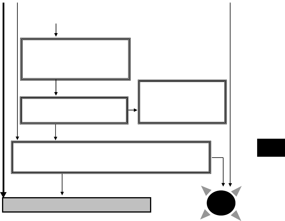
127
Maintenance
Reinstall OS.
Reinstall the OS according to the description in “Chapter 5 Installing OS and
Applications” and check if N22A operates normally. Reinstalling OS causes
applications installed by you and data created by you to be erased.
Contact your sales agent or NEC. Solved
Return system settings to original
values.
Return the system settings to the factory
defaults according to the description in
“Repairing System.”
Not soluble
Delete added applications.
Delete applications installed by you one by
one to check if the trouble can be solved.
Examine applications.
To check if each application is
available to the operating system
or service pack you use, refer
to the User’s Guide or ask your
sales agent or manufacturer.
Not soluble
Not soluble
<Continued>

128
6.1.2 Actions Taken to Solve Trouble (Tips)
Because N22A uses combinations of various applications and peripherals, unexpected
troubles can occur.
The following describes tips to solve troubles appropriately.
Take proper actions calmly.
Neither turn off the power nor click the mouse hastily.
If N22A seems to freeze, it may only take much time to process applications.
If so, wait for a while until the processes are completed.
Write down message on screen if displayed.
Put numeric and English messages on paper because such ambiguous information can
often be good tips for solving troubles.
Guess cause of trouble.
Guess which device caused the trouble among N22A, a peripheral device, an application
or another. The cause may not be identified. However, you can easily take proper action if
identified.
If the trouble may possibly be caused by a peripheral device, remove the peripheral
devices one by one and re-execute the operation in which the trouble occurred. Then you
may identify the peripheral device causing the trouble.
Boot N22A in safe mode
If N22A is not booted normally, boot N22A in the safe mode to check the status and/or
change settings properly.
See “Starting Windows XP in Safe Mode” in “Repairing System”.
Use system information
System information
You can collect the system information including the configuration of N22A and other
related information can be collected to display the information.
The system information helps to search for the data required to solve system
problems rapidly.
- Procedure of displaying [System Information] dialog box.
Click [Start] [All Programs] [Accessories] [System Tools] [System
Information].
System restoration
You can cancel improper changes of N22A to return to the default settings. See the
help of Windows for details.
See Windows help.
Help start procedure
Click [Start] [Help and Support] to display the [Help and Support Center] dialog
box.
Trouble solving procedure:
- Search for tips by “Fixing a problem”
The following operation allows tips to be displayed to solve problems depending on
situations of N22A.
1. Click [Fixing a problem] in the [Help and Support Center] dialog box.
Topics for solving problems appear.
2. Click the topic you want to see.
The details of the selected topic appear on the right window.
3. Click an item you want to see from the list in the window.
The causes and solutions of the trouble appear in the right window. Take
actions according to the directions on the screen.

129
Maintenance
Some items may list trouble situations on the right window. In such a case, click
the applicable situation to select it and click [Next] at the bottom of the window.
The possible causes and resolutions of the trouble appear on the right window.
- Search for desired items by keywords
The following procedure allows you to specify keywords of desired items to search
for tips.
1. Enter a keyword to be checked in the [Search] field of the [Help and Support
Center] dialog box.
2. Click [] next to the [Search] field.
Related topics appear.
3. Select an item from the topics to click it.
The description of the item appears on the right window.
Search “Troubleshooting Q&A” for applicable trouble.
Read the applicable item if found.
See other guides, helps and README files.
If a trouble occurs in an application, refer to the User’s Guide or help of the application.
README files are often provided for applications to include important information which is
not descried in respective user’s guides and helps.
Open the relevant README file by using a text editor such as Notepad to see the file.
Recover system settings to original.
You can return the system settings to the factory default values in the following procedure:
1. Turn on the power of N22A.
2. Press F2 on the NEC Logo screen.
The BIOS Setup Utility Menu screen appears.
3. Press F9.
The confirmation message appears.
4. Confirm that [Yes] is selected and press Enter.
5. Press F10.
The confirmation message appears.
6. Confirm that [Yes] is selected and press Enter.
For details of BIOS setup, see “Chapter 4 Setting BIOS”.
Restore system.
If Windows does not start at all, see “Re-setup” in this chapter to restore the system.
Contact NEC.
For NEC inquiries, see “Maintenance Service” in this chapter.
Before inquiring, enter the failure symptoms on the “Problem Check Sheet” at the end of
this manual. The warranty card includes the model number and other information useful
for remedies, so have it handy for reference.
For troubles on a peripheral, memory device or application purchased separately, contact
the agent of the product.
For troubles of an application attached to N22A, the agent of the application can give
proper responses.
Clicking [Set search options] below the [Search] field allows desired information to be
retrieved from other information sources.

130
6.1.3 Troubleshooting Q&A
(1) Troubles including smoking, heat generation, noise and cable disconnection
Symptoms Action
Smoke and/or odors are generated from N22A.
N22A is heated too hot to make hands contact
with it.
Noises are generated from N22A.
A visible trouble appears on N22A or a cable
connected to N22A.
Turn off the power immediately. Unplug the AC cord from the mating
AC outlet, disconnect the AC adapter from N22A and remove the
battery from N22A. Contact your service representative.
If a car adapter is used, turn off the power immediately. Remove the
plug from the cigar lighter receptacle and remove the car adapter
from this product. Contact your service representative.
Noises are generated from the HDD. Noises are generated from the HDD blinking of the file access lamp.
This is caused by certain operations in the HDD and thus does not
indicate occurrence of an error.
If any abnormal noise, other than the above, is heard, unplug the
adapter and battery and contact your dealer.
Nothing appears on the display screen. When the power lamp is OFF:
− If pressing the power button lightly is not replied by N22A, press
the button hard.
− If the AC adapter is connected to N22A, disconnect the adapter
once and connect it again.
− If the car adapter is used, disconnect it and connect it again.
− If battery power is used, check the remaining battery level and the
installation of the battery in N22A.
For checking procedures, see “Checking Remaining Battery
Level” and “Installing Battery”.
When the power lamp illuminates in green:
− During operation, the power management feature may work to
clear the screen automatically.
Try to press any key to check if the screen display appears.
− The brightness of the screen may be too low. Press Fn + F7 to
increase the brightness.
− Outputting display data to external monitor may be set. Press Fn
+ F3 to alter the display setting.
− Reboot N22A.
A resolution which the LCD display does not support may be set.
After turning off the power of N22A forcibly, start Windows in the
safe mode to reset the resolution.
N22A is halted after POST(Power On Self Test). If an error code appears on the display screen, write down the code
and reboot N22A.
Message “Operating system not found” appears. Confirm that no floppy disk is inserted into the floppy disk drive (if
the floppy disk drive is connected to N22A). If inserted, pull out the
floppy disk and reboot N22A.
If the message appears during booting from the HDD, insert
bootable disk into the external 3.5-in. floppy disk drive or the
external CD-R/RW with DVD-ROM drive to check the HDD status.
Confirm that the HDD is set on the Boot Menu subordinate to the
BIOS Setup Menu.
Message “BOOT: Couldn’t find NTLDR. Please
insert another disk” appears on the display screen.
If an attempt is made to boot N22A from the floppy disk
intentionally, replace the floppy disk with the bootable disk and
press any key to continue booting.
If N22A is booted from the HDD, confirm that a floppy disk is not
inserted in the floppy disk drive (when the floppy disk drive is
connected to N22A). If inserted, remove the floppy disk and reboot
the N22A.

131
Maintenance
Symptoms Action
Pressing the power switch cannot turn on the
power. After removing the AC adapter/car adapter and battery from the
N22A once, reconnect the AC battery to N22A and reinstall the
battery in N22A.
For the battery removal procedure, see “Replacing Battery”. If the
power cannot be turned on still, N22A may be defected. Contact
your service representative or NEC.
The power cannot be turned off. It is desired to
turn off the power forcibly. First follow the procedure in “Turning off power”. If the power cannot
be turned off still, turn off the power forcibly in the following
procedure.
1) Press the power switch continuously for about four seconds or
longer.
− If N22A is set to be entered into the suspend (standby) state by
the power switch, the operation may lead N22A to be the
suspend (standby) state.
In such a case, release the finger from the power switch once
and re-press the switch continuously for longer than four
seconds or longer to shut down N22A forcibly.
− If the power is turned off forcibly to shut down N22A, data not
saved will be lost.
If the power cannot be turned off still, contact your service
representative.
Windows cannot start. The BIOS Setup Menu may be set incorrectly. Return the settings of
the BIOS Setup Menu to that at purchase according to “Chapter 4
Setting BIOS”. Then turn on the power again.
The extended option menu of Windows appears. The extended option menu may appear if Windows was shut down
improperly last or cannot be started normally due to some start error.
Restart Windows in the safe mode according to “Repairing System”.
Message “Checking file system on” appears on
the display screen. In the next start of Windows after illegal termination, the HDD may
be checked to be valid on the way of the starting. Without errors,
Windows is started normally.
If not, follow the directions shown on the display screen.
(2) Battery troubles
Symptoms Action
The battery cannot be charged (the battery
charging lamp does not illuminate in orange.) The battery is not charged in full charge status and may not be
charged in nearly full charge status. Check the battery capacity.
Confirm that the AC adapter is connected to N22A properly.
If the battery temperature is less than 0ºC or higher than 60ºC,
charging the battery is not started. Wait until the temperature
returns to be in the range from 5 to 50ºC.
Confirm that the battery is installed in N22A properly.
Check if the pins on the battery are dirt.
The battery fully charged can operate N22A only
for a shorter period. Repeating incomplete recharge and discharge frequently may
disable the battery to be charged fully. To solve the problem,
initialize the battery (see “Initializing Battery” for details).
The battery operation time shown by the OS
battery meter does not match the actual operation
time.
The actual operation time may be different from the estimated
operation time depending on how N22A is used. If the actual
operation time is shorter extremely, initialize the battery (“Initializing
Battery” for details).

132
(3) AC adopter troubles
Symptoms Action
Power is not supplied even though the AC adapter
is connected. The power lamp blinks red.
It is the voltage error if the power lamp is blinking in red and green
alternately at 0.5-second intervals.
Stop using the AC adapter and contact your dealer.
(4) Display troubles
Symptoms Action
The screen is dark considerably. Adjust the brightness by using Fn + F7 or the relevant tablet button.
The resolution cannot be adjusted to the desired
value. Confirm that the video driver is installed properly.
Check the BIOS Setup Menu to confirm that the video memory is
configured properly.
If an external monitor is used, confirm that the monitor supports the
desired resolution.
Nothing appears on the external monitor. Confirm that the power of the monitor is ON.
Confirm that the monitor signal cable is connected properly.
Change the selected monitor to the external one by pressing Fn +
F3 or through the Windows [Display] roperty.
The concurrent display feature does not operate. Turn on the power of the external monitor before turning on the
power of N22A.
Select the desired display option by pressing Fn + F3 or through the
Windows [Display] property.
Windows cannot be started after BIOS setting is
changed. In the next start of Windows after illegal termination, the HDD may
be checked to be valid on the way of the starting. Without errors,
Windows is started normally. If not, follow the directions shown on
the display screen.
The original screen before entering into the power
saving state does not appear. Some applications or peripheral devices may operate improperly when
an attempt is made to use the suspend (standby) feature. Turn off the
power of N22A once and on again.
If the power cannot be turned off, press the power switch continuously
for four seconds or longer to
shut down N22A forcibly. To use an application or peripheral device
of such type, do not enter N22A into the suspend (standby) state.
The command prompt (MS-DOS prompt)
window appears on the full screen.
Press Alt + Enter.
With the command prompt (MS-DOS prompt)
being active, the screen does not appear after
recovery from the suspend (standby) state.
Press Alt + Tab to alter the task. Then N22A operates normally.
The LCD brightness is lowered when using the
N22A in a high–temperature environment.
When using the N22A in a high-temperature environment while the
LCD brightness is set to high for a long period of time, the internal
temperature may rise. In such a case, the LCD brightness is
automatically lowered or cannot be raised, to extend the LCD life.
(5) Troubles of hardware devices
Symptoms Action
N22A does not recognize a device newly
installed. The devices may be configured improperly on the BIOS Setup
Menu.
Confirm that the used peripheral port is set to [Enabled] on the
BIOS Setup Menu.
Check if the relevant device driver should be installed.
Check if the device requires one or more jumper and/or switch
settings.
For an external device, check if the connection cable such as a USB
cable and the power cord are connected properly.
If the external device has its own power switch, confirm that the
power is turned on.

133
Maintenance
(6) Troubles of HDD
Symptoms Action
After power-on, N22A does not recognize the
HDD. Confirm that the type of the HDD is configured properly on the BIOS
Setup Menu.
An error message on the HDD appears on the
display screen. Insert the bootable disk to the external 3.5-in. floppy disk drive or
the CD-R/RW with DVD-ROM drive to check the consistency of
the HDD.
The HDD may possibly be defected. Contact your service
representative.
The HDD can operate only slowly. Data files stored in the HDD may be fragmented. Optimize the files
by using such a tool as Windows defragmenter.
The indicator indicating use of the HDD does not
blink but remains ON. Data files stored in the HDD may be fragmented. Cancel the file
fragmentation by using such as tool as Windows defragmenter.
The empty capacity in the HDD is not enough. The empty capacity in the HDD can be increased in the following
ways:
− Delete all files in the Recycle Bin.
− Reduce the maximum size of the Recycle Bin.
(If the maximum size of the Recycle Bin is set to 0%, deleted
files are rejected without storage in the Recycle Bin.)
− Deletes contents in the TEMP folder.
(Do not delete the primary working file while one or more
applications are executed. Deleting the primary working file may
cause applications not to operate.)
− Delete temporary files for Internet Explorer.
− Delete one or more installed applications.
(Deleting applications not used at the moment allows the empty
capacity in the HDD to be increased.)
− Click [Disk Cleanup] to delete unnecessary files in the HDD.
The empty capacity in the HDD does not increase
after unnecessary files are dumped into the
Recycle Bin.
Files deleted or drugged to the Recycle Bin are not deleted from the
HDD immediately but stored in the Recycle Bin.
To delete files stored in the Recycle Bin from the HDD, right-click
the Recycle Bin icon to display the menu and click [Empty Recycle
Bin] in the menu.
(7) Troubles in file storage
Symptoms Action
Data cannot be stored in the HDD. Check the empty HDD capacity. If not enough, increase the empty
capacity according to “Empty HDD capacity is not enough” on [Hard
Disk]. Any file larger than the empty disk capacity cannot be saved.
Data cannot be stored in the floppy disk. Check if the floppy disk is subjected to write-protect. If so, release
the write-protect.
Check the empty capacity of the disk. If the empty capacity is not
enough, reject unnecessary files or use another floppy disk.
Data cannot be stored in the SD card. Check if the write-protect switch on the SD card is set to [LOCK]. If
so, release it.

134
(8) Troubles of keyboard, mouse and touch pad
Symptoms Action
The keyboard does not respond to any inputs. Connect an external USB keyboard to N22A and check if the
keyboard can operate properly. If so, the built-in keyboard cable may
be defected. Contact your service representative.
The numerical keypad is disabled. Confirm that [Num Lk] is ON (the NumLk LED illuminates in
green).
The external USB keyboard and/or USB mouse
do not operate. Check if the USB cables are connected properly.
The serial mouse does not operate. Confirm that the mouse cable is connected properly.
Connect the mouse before booting N22A.
Confirm that the serial port is enabled on the BIOS Setup Menu.
The touch pad does not operate or makes
responses only slowly. Check if the touch pad is dirt.
If operated by excess force or other than finger cushions, the touch
pad may operate improperly.
If you touch more than one point, the touch pad does not operate
normally.
The touch panel does not operate or the pointer
operates invalidly. Confirm that the driver and utility software of the touch panel are
installed.
Calibrate the touch panel by using the utility software.
(9) Troubles of network (LAN)
Symptoms Action
N22A cannot connect with network. The connection may be invalid. Contact your network administrator
to check if N22A is connected to the relevant hub through a LAN
cable.
The setting may be invalid. For example, the protocol or the domain
work group may be set improperly or the computer account may not
be put on the primary domain controller. For details, ask your
network administrator.
Only the [Whole Network] icon appears in the
[My Network] or [Network Computer] dialog
box.
It may take a rather long time until the display appears. Wait for a
while and click [Refresh] on the [View] menu. If the display status
remains unchanged, the network may be connected improperly or
network software may be set inappropriately.
Check the connection and network software.
Only the own computer appears in the [My
Network] or [Network Computer] dialog box. It may take a rather long time until the display appears. Wait for a
while and click [Refresh] on the [View] menu. If the display status
remains unchanged, check if the domain or work group to be
connected matches the setting domain or work group.
To see the setting domain or work group, click [Start] [Control
Panel] [Performance and Maintenance] [System] to display the
[System Properties] dialog box and select the [Computer Name] tab on
the dialog box.

135
Maintenance
Symptoms Action
Shared drives and/or folders are unavailable. Check if the Microsoft network share service is installed in
N22A by clicking [Start] [Connect To] [Show all connections]
to display the LAN connection icon, right-clicking the icon, clicking
[Properties] and checking column “This connection uses the
following items:” in the [General] tab.
If not, shared drives and folders are not available. To use them,
install the share service.
Check if N22A is set to access to shared drives and folders. To allow
other computers connected to the network to use drives and/or
folders in N22A, drives and folders to be shared should be set for
share. For the purpose, right-click a drive or folder to be shared to
display the menu, click [Sharing and Security ...] in the menu and
check “Share this folder on the network” in the [Property] dialog
box. After the setting, the drive or folder icon changes to be suit to
share.
Check if certain access authorities are set for shared drives and
folders. The owner of a shared drive or folder can set its access
authority.
The access authority of a drive or folder defied to be shared is first
set to “read only”. Other users can read data from the drive or folder
but cannot write data to it.
Pressing F12 cannot make network booting. Pressing F12 on the NEC logo screen may not be able to run the
network boot process. In this case, press F12 on the NEC logo screen
several times. If the network boot process is not executed still, change
the interval at which F12 is pressed.
N22A operates only unstably. state during communication, N22A may operate improperly. Do not
enter N22A into the suspend (standby) or pause state during
communication. Release the setting that the Windows power
management feature may enter N22A into the suspend (standby) state
automatically if the setting is provided.
(10) Troubles of wireless LAN
Symptoms Action
Communication is disabled. Check that the wireless communication switch is on.
Press Fn + F2 to alter ON/OFF of the wireless LAN feature.
On the [Wireless Network Connection Status] dialog box, [Disable]
of the wireless LAN feature may be checked.
Click [Start] [Connect to] [Wireless Network Connection] to
check the setting.
Check if the power of devices to be connected are turned on
according to the User’s Guides of the devices.
Confirm that the SSID (network name) is set properly. To connect
to a wireless LAN access point, set the SSID to be the same as the
ID of the access point.
With data encryption, confirm that the encryption key is set
correctly. Set a specific encryption key for all wireless LAN access
points and computers connected to N22A.
Check if the environment is set properly. Set the environment again
if necessary.
Communication is disabled intermittently or the
communication speed is too late. The wireless LAN device to be connected may be located too far
from N22A. Check the radio wave environment. In poor radio wave
environment, make the wireless LAN device close to N22A.
The possible distance between N22A and a wireless LAN device
varies depending on device specification.
If one or more wireless devices only conforming to IEEE802.11b
exist in a range where radio wave can be radiated to a connected
wireless LAN access point conforming to IEEE802.11g, the
communication speed for IEEE802.11g decreases.
If a wireless device only conforming to IEEE802.11b connects to
another access point, only reach of radio wave to the access point
influences the communication speed.

136
Symptoms Action
Communication is disabled intermittently or the
communication speed is too late. If a microwave oven is used in an area where communication with
2.4 GHz wireless LAN device occurs, the communication speed and
distance of the 2.4 GHz wireless LAN device may be reduced.
It is recommended that microwave ovens are not used near 2.4 GHz
wireless LAN devices.
Concurrent communication of 2.4 GHz wireless LAN and
Bluetooth devices may decrease the communication speed and/or
distance of devices of each type. It is recommended not to operate
either 2.4 GHz wireless LAN or Bluetooth devices or keep them
away from each other.
If more than one computer are connected to a network, increase in
the number of computers connected to a single wireless LAN access
point may cause the transmission speed per computer to decrease.
A remote computer does not appear in [Network
Computer]. Check computer names. A computer connected to N22A may have
the same name. Give a unique name to N22A.
If a remote computer does not have the “File and Printer Sharing for
Microsoft Network” service, the PC does not appear in the
[Wireless Network Connection Properties] dialog box. Install the
service in the remote computer.
Check if the TCP/IP protocol is installed in N22A. Set the IP
address properly to be appropriate for the network connected.
The surrounding radio wave status may be bad. Shorten the distance
to the remote computer connected to N22A and/or remove obstacles
between N22A and the remote PC. Then connect N22A to the
remote device again.
The remote computer may be just booted. After several minutes,
check the connection status again.
Double-clicking the icon of a remote computer in
[Network Computer] cannot indicate the
information on the PC.
Check if shared folders and printers exist in remote computers. Set
folders and printers to be shared on remote computers to “Sharing and
Security...”.
Connection with an access point is cut off without
notice. If more than one access point exist in the surrounding area, the
connection is automatically switched to another access point
depending on settings of access points. If another access point uses the
same SSID (network name), change the SSID.
A wireless LAN cannot be used prior to log on to
Windows. Enable “Before log-on/common: active while a user is logging on.
All users share this profile” of management profile type for wireless
LAN setting.
For how to set, refer to CHAPTER 2 USING THIS PRODUCT
WIRELESS LAN.
(11) Bluetooth-related failure
Symptoms Action
Communication is not possible. Make sure the wireless communication switch is on.
Check whether the Bluetooth function is disabled in the Wireless
network connection. If it is disabled, enable the function.
Communication disconnects. Connect the line again.
Disconnection of communication takes long. It may take much time to disconnect Bluetooth devices.

137
Maintenance
(12) Troubles of PC card
Symptoms Action
The PC card does not operate. Confirm that the PC card is inserted properly.
If the card requires an IRQ, confirm that at least a single IRQ is not
used.
The PC card provides communication improperly.
The relevant application might be reset when N22A was entered into
the suspend (standby) or pause state. Abort the application once and
start it again.
(13) Troubles on power management
Symptoms Action
N22A does not enter into the suspend (standby) or
pause state automatically. If N22A is connected to another computer or a bi-directional printer
accessing to N22A at constant intervals, N22A is not entered into
the suspend (standby) or pause state automatically.
Confirm that the timeout of the suspend (standby) or pause state is
enabled.
Check if one or more programs are executed. Abort all programs
being executed if any. In addition, first cut the phone line if used
before entering N22A into the suspend (standby) state.
Some applications may operate improperly if a peripheral device
tries to use the power management feature. Turn off the power of
FCN21S once and then on again.
To use an application or peripheral device of such type, do not enter
N22A into the suspend (standby) state.
N22A does not immediately enter into the
suspend (standby) or pause state. In general, if N22A executes some operation, wait until the
operation is terminated.
The used PC card may prohibit N22A from entering into the
suspend (standby) or pause state. To enter N22A into either of the
state, abort the communication program and remove or halt the
card.
If a file or program stored in the disk inserted in the floppy disk or
CD-ROM drive connected to N22A through USB is opened or
executed, close the file or abort the program. Then the N22A can be
entered into the suspend (standby) or pause state.
For memory extension, the empty capacity by the extended memory
capacity is required in the HDD. Check the capacity of the HDD.
If “Enable hibernation” is not checked or it is checked but the state
when portable computer is closed or power button of computer is
pressed is not set to the pause state, N22A cannot be entered into
the pause state. Make proper settings according to “Pause state and
recovering from pause state”.
N22A does not resume from the suspend
(standby) or pause state. When the battery is discharged completely, N22A automatically
enters into the suspend (standby) or pause state. Take either of the
following actions:
− Connect the AC adapter to the N22A.
− Replace the fully discharged battery with a fully charged battery.
If an attempt is made to resume N22A from the
suspend (standby) or pause state, the screen is
disturbed and the power is turned off.
If the LCD display panel is closed or the power is turned off during
transition to or recovery from the suspend (standby) or pause state,
N22A may not be able to resume. In this case, turn on the power by
using the power switch. If an error message appears, follow the
direction of the message.
The power cannot be turned off. “Turning off power”, an error such as application freeze may occur.
Press Ctrl + Alt + Del to abort the application forcibly and turn off
the power by the procedure described in “3.2.2.2 Turning off power”.

138
(14) Software troubles
Symptoms Action
An application program operates improperly. Confirm that the application program is installed properly.
If an error message appears on the display screen, refer to the
documentation of the application program to search for required
information.
If N22A is shut down clearly, reboot N22A.
<Resetting N22A>
If an error occurs to cause programs being used to hang, N22A may
have to be reset (rebooted).
If N22A seems to hang, wait for a while. N22A may provide data
processing.
Check the LED indicating use or no use of the HDD periodically.
If the LED blinks irregularly, programs may access to the HDD to
disable the keyboard. When N22A does not operate at all and the
“Restart” feature of OS is unavailable, reset N22A.
Follow the procedure below to reset N22A:
1. Press Ctrl + Alt + Del.
2. If the above step does not work well, continue to press the power
button for four seconds or longer to shut down N22A. Wait for
five seconds or longer and turn on the power of N22A again.
The reset operation erases all data not stored.
(15) Sound troubles
Symptoms Action
Sound does not replay. Check if the mute feature is enabled.
Click [Start] [Control Panel] [Sounds, Speech and Audio
Devices] [Sounds and Audio Devices] to display the [Sound and
Audio Devices Properties] dialog box. If the [Mute] checkbox in the
[Volume] tab of the [Sound and Audio Devices Properties] dialog
box is checked, uncheck the checkbox.
Confirm that the volume level is not set to too low.
The volume may often be too low. Press Fn + F9 to turn up the
volume.
Confirm that the sound driver is installed properly.
Confirm that N22A is not in the suspend (standby) state.
If external speakers are used, confirm that they are connected to
N22A properly.
Sound is replayed but distorted. Confirm that the volume is set to neither too high nor too low. In most
cases, because the volume is set to too high, some electronic audio
parts lead sound distortion.
The sound system fails in recording. Adjust the replay or record sound level.
An external microphone or sound device does not
operate. Confirm that a microphone is connected to the mating connector on
N22A properly.
Click the speaker icon on the task bar to check the Windows
volume.
Check the volume control of N22A.

139
Maintenance
(16) Troubles of optional CD-R/W with DVD-ROM drive FC-CW002U
Symptoms Action
The CD-R/W with DVD-ROM drive does not
read CD data. Confirm that the CD is properly put on the tray with the label facing
upward.
Confirm that the CD is not dirt. If dirt, clean the CD with CD
cleaning kit. You can procure CD cleaning kit from most computer
shops.
Confirm that the DVD/CD-ROM driver is installed properly.
The CD or DVD cannot be pulled off. The CD/DVD is not put on the drive properly. Take out the CD/DVD
manually in the following procedure:
1. Turn off the power of N22A.
2. Insert a thin needle-shaped wire such as extended paper clip into
the manual ejection hole on the drive and push the wire hard. Then
the tray is ejected.
3. Pull out the tray completely and take out the CD/DVD.
(17) Troubles of optional floppy disk drive FC-FD002U
Symptoms Action
The indicator indicating that the floppy disk drive
is being used remains ON. Confirm that the floppy disk is not damaged physically.
Confirm that the floppy disk is inserted properly.
Writing data to the floppy disk is disabled. Confirm that the floppy disk has already been formatted.
Confirm that the floppy disk is not write-protected.
Confirm that a proper drive is selected for writing.
Confirm that a sufficient empty capacity remains in the floppy disk.
Confirm that the floppy disk is not damaged physically.
Reading data from the floppy disk is disabled. Confirm that the floppy disk has already been formatted.
Confirm that a proper drive is selected for reading.
(18) Battery charger failure (option FC-BC01N)
Symptoms Action
The charger is broken. Stop using the charger and contact your dealer.
The battery cannot be inserted into the battery
charger. Check the connector position of the battery for correct insertion
orientation.
(19) Car adapter failure (Option FC-VA01N)
Symptoms Action
The car adapter is broken. Stop using the adapter and contact your dealer.
The main unit is not supplied with power,
although the car adapter is connected.
The car adapter LED does not glow.
Connect the cigar lighter plug again.
Conduction is not possible unless the cigar lighter plug is properly
connected to the cigar lighter receptacle.
(20) Wide temperature range model failure
Symptoms Action
The system does not operate or operation is
unstable although it is used in the operating
temperature range (-20C to 50C) for
wide-temperature-range operating models.
Makes sure that the device main unit, hard disk, and battery support
the wide temperature range.
Wide-temperature-range operation is possible only when the device
main unit, hard disk, and battery support the wide temperature range.

140
(21) Password troubles
Symptoms Action
After password entry, message “An invalid
password is entered” appears. Check the password again and reenter it properly.
Check if the [Caps Lock] or [Num Lock] key lamp illuminates. If
the [Caps Lock] or [Num Lock] key lamp illuminates, the password
may be unable to be entered properly.
If [Caps Lock] key lamp illuminates, press Shift + Caps Lock to
release it. Then enter the password.
If [Num Lock] key lamp illuminates, press Fn + F12 to release it.
Then enter the password.
The password is forgotten. If you forget the Windows password, there is no means to find the
password directly. Take any of the following actions:
− Click to the right of the “type your password” field on the
Windows logon screen to check the tip of the password.
− Logon to N22A with another user account.
− Ask a person having an administrator account of N22A to create a
new password.
If you forget the supervisor password, contact your service
representative.
(22) Miscellaneous
Symptoms Action
The date and/or clock go wrong. If the device is stored at a high or low temperature, the internal clock
may deviate. In this case, reset before use.
Check the clock of OS and the BIOS Setup Menu to find the system
time (OS) and the RTC clock (BIOS).
When the system time goes wrong:
The operated application software may be defected. Abort the
software and set the date and time again. If the system time goes
wrong still, contact your service representative.
When the RTC time (BIOS) goes wrong:
The power of the calendar clock built in N22A is supplied by a
battery. Accordingly, the calendar clock can continue operating
if the power of N22A is turned off. If the date and/or time go
wrong after resetting, the backup battery may reduce its
necessary level or a hardware error may occur. Contact your
service representative.
It is desired to use N22A in other than Japan. Contact your service representative. NEC does not provide any
maintenance service in countries and regions other than Japan.
141
Maintenance
6.2 RE-SETUP OF Windows XP IN N22A OF
PRE-INSTALLED MODEL
6.2.1 Re-setup
Re-setup can recover the damaged system of N22A to the normal state.
However, files stored in the HDD are erased. In addition, it takes much time for re-setup. Check
if re-setup is absolutely required before starting the job.
(1) Situations requiring re-setup
Provide re-setup for the system in N22A in the following situations:
1. Recovering system from trouble
At power-on, the power lamp goes on but Windows does not start.
One or more programs in the HDD do not operate.
System files in the HDD are erased unintentionally.
Repairing the system cannot solve problem.
Started Windows XP in the safe mode, but problem cannot be solved.
2. Changing settings of Windows
The settings of Windows are required to be recovered to the factory defaults.
3. Changing the settings of the HDD
The capacity of drive C is required to be changed.
The HDD is required to be configured with only a single partition.
(2) System repair procedure
The system can be repaired in either of the following two ways. The proper way is
dependent on the system status. Try the simpler method first in the order shown below:
1. Repair the system by using the [Last Known Good Configuration] menu.
2. Provide the system with re-setup by using the recovery CD-ROMs.
Notes on re-setup
Make a backup of data.
Some re-setup methods may erase all or a part of data you have created. For the re-setup
methods, see “Standard and Custom Re-setups”.
Write down the settings of N22A.
Re-setup returns all settings including network settings to the factory defaults.
To use N22A with the same settings as the current ones after re-setup, write down the
current settings of N22A.
Remove peripheral devices purchased separately from N22A.
Provide re-setup under the condition that devices coming with FC-N21C are only connected
to N22A.
Peripheral devices purchased separately should be connected to N22A after re-setup.
If a supervisor password is set, cancel the supervisor password or change the BIOS
SETUP as follows:
Select [Security] [Password on boot] [Disabled].
For the supervisor password, see “Chapter 4 Security”.
Do not suspend re-setup.
After starting re-setup, be sure to complete it according to the procedure described in this
guide. If suspended, restart the re-setup from the beginning.
The re-setup is to return the system in N22A to that in the same state at shipment from factory
based on the data stored in the recovery CD-ROMs if the system is damaged.
The re-setup is also required after the configuration of the HDD is changed. It is because
formatting (initializing) the HDD causes the system to be erased.
142
6.2.2 Standard and Custom Re-setups
There are two re-setups, or standard and custom re-setups. The following describes four
re-setup patterns.
(1) Standard re-setup
Every hard disk drive in N22A can be returned to the factory default. Beginners and users
unfamiliar with HDD should always follow the procedure for re-setup.
(2) Custom re-setup
For re-setup of drive C only or change of the capacity of drive C, follow the procedure.
Select any of the following three procedures and go to Subsection “Custom Re-setup”.
1. Re-setup of drive C only in the NTFS format.
Provide only drive C in the built-in HDD with re-setup in the NTFS format.
Drive D and the other drives are not formatted and the data in the drives is left as it is.
* The capacity of drive C is not changed.
2. Re-setup of entire HDD area to a single partition
Provide the entire area of the built-in HDD with re-setup to a single partition in the
NTFS format. Drive C can have the maximum capacity.
Data in the built-in HDD is erased completely. Be sure to make backup copy of the
data.
3. Free re-setup of HDD area (re-setup by user setting)
Provide the area of the built-in HDD with re-setup to a combination of partitions of
5GB or larger in 1GB freely.
Data in the built-in HDD is erased completely. Be sure to back up the data.
For file systems NTFS, FAT32 and FAT16, click [Start]
[Help and Support]. (Searching with
keyword such as “File System”, you can view the detailed information.)

143
Maintenance
6.2.3 Repairing System
The following describes the troubleshooting procedures when the system cannot be started
normally due to change of system configuration.
Repairing System by Using Configuration in the Last Normal Starting
If starting Windows XP is disabled after some system change, the problem can be solved by
using the configuration in the last normal starting.
The configuration changes made after the last normal starting are all discarded.
If the system is started normally more than once after configuration change, the
configuration before the change cannot be recovered.
To use the configuration on the last normal starting, follow the procedure below:
1. Start Windows XP being defected.
2. If message “For troubleshooting and advanced startup options for Windows,
press F8.” appears on the screen, press F8.
3. If [Windows Advanced Options Menu] appears, select [Last Known Good
Configuration] and press Enter.
4. On the operating system selection menu, press Enter.
The [Hardware Profile/Configuration Recovery Menu] dialog box appears.
Any of the following options can be selected on the menu.
Hardware profile selection used at startup of this device
Switch configuration at previous normal startup
Reboot this device
System repair
5. To restart Windows XP in the configuration before occurrence of the problem,
press L. Then press Enter.
Windows XP is started by using the configuration at the last normal starting.
Starting Windows XP in Safe Mode
The safe mode is a specific diagnostic mode intended to allow Windows to be started normally.
Follow the procedure below to start Windows in the safe mode:
1. Start Windows XP.
2. If message “For troubleshooting and advanced startup options for Windows,
press F8.” appears, press F8.
3. Select start option “Safe Mode” and press Enter.
Windows XP is started in the safe mode.
Repairing System by Using [System Restore]
If using the safe mode or the configuration on the last normal starting cannot start Windows XP
normally, use [System Restore] to repair the system.
This method allows N22A to be recovered to the previous state without discarding the personal
data files.
To start [Restore System], click [Start] [All Programs] [Accessories] [System Tools]
[System Restore].
For details, click [Start] [Help and Support] to see the information. (You can search with
keyword “system repair” for the detailed information to be viewed.)
144
6.2.4 Standard Re-setup
Repairing System by Using Recovery CD-ROMs
The Recovery CD-ROMs attached to N22A can be used to recover the information stored in
the HDD to factory defaults.
(1) Tools to be prepared
The following tools are required for re-setup by using the recovery CD-ROMs.
Prepare the following CD-ROMs attached to N22A.
Recovery CD-ROMs (WinXP)
CD-R/RW with DVD-ROM drive (FC-CW002U)
In addition, the user name and computer name must be entered.
Define the names to be registered previously.
(2) Check items before re-setup
Be sure to return BIOS settings to the factory defaults if changed.
For how to return BIOS settings to the factory defaults, see “Chapter 4 Loading the BIOS
SETUP Defaults”.
(3) Notes on re-setup
Do not connect or add peripherals including a printer or memory devices.
Before the re-setup is completed, any peripherals including a printer and extended
memory devices should never be connected to N22A. If these peripherals are
purchased concurrently with N22A, first complete the setup of Windows XP to be
followed by connections and installations of the peripherals according to the user’s
guides coming with the peripherals.
Be sure to connect the AC adaptor all the way of re-setup.
Do not turn off the power on the way.
Do not turn off the power in the middle of the setup. Setting the power switch to OFF or
disconnecting the power cable in the middle of the setup may cause a fault to occur. If
the screen seems to stop on the way, the setup program may operate. This does not
indicate that the system is defected. Advance the operation according to the defined
procedure without panic.
(4) System Restoration Procedure
1. Turn on the power of N22A.
2. As soon as the power lamp goes on, insert “Recovery CD-ROM (WinXP)” into
the CD-ROM drive.
3. If the following dialog box appears, press Enter.
Separate “Recovery DVD-ROM Media” for Japanese and English version preinstalled models
are included one copy for each.
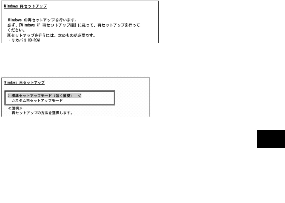
145
Maintenance
4. If the following dialog box appears, select [標準再セットアップモード(強く推
奨)] and press Enter.
5. Follow the direction on the dialog box to provide re-setup.
For the subsequent steps, follow the directions on the dialog box.
Now the HDD is completely restored to the factory defaults.
Then provide re-setup for Windows XP.
(5) Re-setup of Windows XP
If the power of N22A is turned on for the first time after system restoration by using the
recovery CD-ROMs, the Windows XP setup job including entry of your name is required. It
takes about 30 minutes to complete the job.
1. Reboot N22A after the system restoration job is completed. If the [Welcome to
Microsoft Windows] screen appears, click [Next].
2. The [The End User License Agreement] screen appears. Click the scroll button
to read it thoroughly.
3. After reading, click [Yes, I accept]. Then click [Next].
Clicking [No, I don’t accept] disables the setup job to be started.
4. If the [Help protect your PC] dialog box appears, select [Not right now] and
click [Next].
5. If the [What’s your computer’s name?] dialog box appears, enter any name in
the name field.
The factory default of [Computer name] is “FCN22A-XXXXX” (XXXXX: lowest five digits of
product ID).
The computer name can be changed later.
[Computer description] is empty at shipment.
6. Click [Next].
7. If the [What’s your Administrator password?] dialog box appears, enter a
password in the password field.
The password field is empty at shipment.
The password is case sensitive.
The password can be changed later. The password entered here must be reentered in the
re-setup job. Take note of the password for remembrance.
8. Click [Next].
9. If message “Is this computer in a domain?” appears, select [Yes] or [No].
146
(The following describes the operation after you select [No].)
10. Click [Next].
11. Message “Checking your Internet connectivity” appears and then message
“How will this computer connect to the Internet?” appears.
12. Click [Skip].
13. Message “Ready to register with Microsoft” appears.
14. Select “No, not at this time” here.
15. Click [Next].
16. If message “Who will use this computer” appears, enter a user name.
Default user name: FC-USER
Without entering a user name, you cannot advance to the next step.
The data in [User Name 1] is registered as the user of [System Properties].
17. Click [Next].
18. Message “Thank you!” appears.
19. Click [Finish].
20. Message “Please wait…” appears. Wait until the screen changes without any
operation.
21. If the [Logon to Windows] screen appears, enter the password set in step 7
and click [OK].
22. Wait until the desktop screen appears.
Before the desktop screen, the [Change System Settings] screen may appear.
Before the desktop screen, the [Change System Settings] screen may appear.
In this case, wait until the desktop screen appears, click [Finish] on the [Introduction to
Windows XP] screen and click [Yes] on the [Change System Settings Screen] screen to
restart the system.
Now the operation is completed.
After re-booting, the [Welcome to the Found New Hardware Wizard] dialog box may appear.
If this occurs, provide proper settings in the following procedure:
1. If [Welcome to the Found New Hardware Wizard] appears, click “No, not this time” and then
click [Next].
2. Click “Install the software automatically” and then click [Next].
Message “Please wait while the wizard installs the software …” appears.
3. If the [Completing the Found New Hardware Wizard] dialog box appears, click [Finish].
Because WindowsXP automatically recognizes USB keyboard and mouse, specific settings
are not required.
In use of a USB keyboard,
[Standard 101/102 –Key or Microsoft Natural PS/2 Keyboard] or [PS/2 Compatible Mouse]
may appear when you click [Start] [All Programs] [Accessories] [System Tools]
[System Information] and select [Components] [Problem Devices] in the [System
Information] dialog box.
This is a view-only problem. The USB keyboard can operate normally without any
problems.
If the keyboard or mouse is reconnected, the key layout may be set improperly.
If so, see “(6) Notes on change to keyboard or mouse of different key layout” described
below.

147
Maintenance
(6) Notes on change to keyboard or mouse of different key layout
If the current keyboard or mouse is changed to another one, the new keyboard or mouse
may operate improperly. If so, change the key layout of the keyboard in the following
procedure:
1. Click [Start] [Control Panel].
2. Click [Date, Time, Language, and Regional Options] and [Regional and
Language Options].
3. Click [Details…] in [Text services and input languages] of the [Language] tab.
Note: If you find the desired keyboard layout in the list of installed services, go to
step 7.
Click [Add] in [Installed services].
4. Select the language of the keyboard layout to be added from the [Input
language:] list.
5. If [Keyboard layout/IME:] has only a single option, click the option.
If more than one options are available, open pull-down menu [Keyboard
layout/IME:] and select the desired option from the list.
6. Click [OK].
7. Click the language of the used keyboard layout from the [Default input
language] list.
8. Click [OK].
9. Click [OK].
Installing Attached Applications
Install attached applications with re-setup.
For the re-setup procedure, see “Chapter 5 Installing Attached Applications”.
Providing Settings Made after Purchase Again
Any settings made after purchase are discarded by re-setup. Provide the settings again.
Reconnect peripherals purchased separately if any and provide settings for the peripherals
again. Also make network setting.
In addition, reinstall applications purchased separately and having been installed if any.
148
6.2.5 Custom Re-setup
The HDD can be restored to specified status by using the attached Recovery CD-ROMs.
Checking Items
(1) Tools to be prepared
The following tools are required for re-setup by using the recovery CD-ROMs.
Prepare the following CD-ROMs attached to N22A.
Recovery CD-ROM (WinXP)
CD-R/RW with DVD-ROM drive (FC-CW002U)
In addition, the user name and the computer name must be entered.
Define the names to be registered previously.
(2) Check items before re-setup
Be sure to return BIOS settings to the factory defaults if changed.
For how to return BIOS settings to the factory defaults, see “Chapter 4 Loading the BIOS
SETUP Defaults”.
(3) Notes on re-setup
Do not connect or add peripherals including a printer or memory devices.
Before the re-setup is completed, any peripherals including a printer and extended
memory devices should never be connected to N22A. If these peripherals are
purchased concurrently with N22A, first complete the setup of Windows XP to be
followed by connections and installations of the peripherals according to the user’s
guides coming with the peripherals.
Do not turn off the power on the way.
Do not turn off the power in the middle of the setup. Setting the power switch to OFF or
disconnecting the power cable in the middle of the setup may cause a fault to occur. If
the screen seems to stop on the way, the setup program may operate. This does not
indicate that the system is defected. Advance the operation according to the defined
procedure without panic.
System Restoration Procedure
1. Turn on the power of N22A.
2. If the power lamp goes on, insert the first Recovery CD-ROM disk (WinXP) in
the CD-ROM drive.
3. If the following dialog box appears, then press Enter.
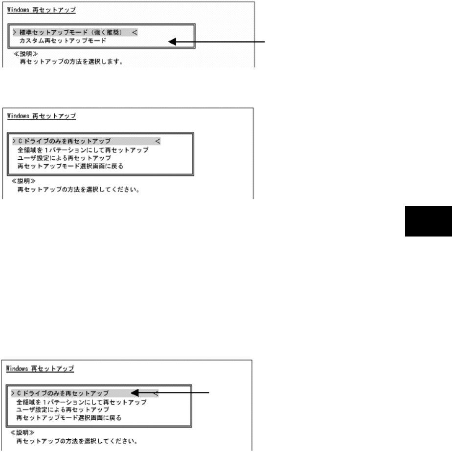
149
Maintenance
4. If the following dialog box appears, select [カスタム再セットアップモード] and
press Enter.
5. The following dialog box appears.
Select one of the following three procedures.
(1) [C ドライブのみを再セットアップ]
(2) [全領域を 1 パーティションにして再セットアップ]
(3) [ユーザ設定による再セットアップ]
(1) Re-setup of drive C only (NTFS)
If the HDD to be subject to re-setup has an unassigned area larger than drive C, re-setup
of drive C only may be disabled.
If so, retain the unassigned area as a partition before selecting [C ドライブのみを再セッ
トアップ].
1. If the following dialog box appears, select [C ドライブのみを再セットアップ]
and press Enter.
2. If message “C ドライブに Windows XP を再セットアップします。よろしいです
か?” appears on the dialog box, select [Yes] and press Enter.
For the subsequent steps, follow the directions on the dialog box.
If the [Windows XP Setup Wizard] dialog box appears after restarting, then the following
operation is the same as that for the standard re-setup.
Perform the operation according to the description in “Repairing System by Using
Recovery CD-ROMs”.
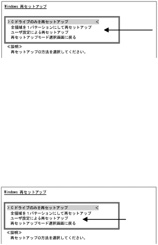
150
(2) Re-setup by combining entire area into a single partition (NTFS)
Select [全領域を 1 パーティションにして再セットアップ] on the [WindowsXP 再セット
アップ] dialog box and press Enter.
1. If the following dialog box appears, select [全領域を 1 パーティションにして再
セットアップ] and press Enter.
2. If message “ハードディスクの全領域をフォーマットして Windows XP を再セッ
トアップします。よろしいですか?” appears on the dialog box, select [Yes] and
press Enter.
For the subsequent steps, follow the directions on the dialog box.
If the [Welcome to Microsoft Windows] dialog box appears after restarting, then the
following operation is the same as that for the standard re-setup.
Perform the operation according to the description in “Repairing System by Using
Recovery CD-ROMs”.
(3) Re-setup with free setting of HDD area (NFTS)
Select [ユーザ設定による再セットアップ] on the [WindowsXP 再セットアップ] dialog
box and press Enter.
1. If the following dialog box appears, select [ユーザ設定による再セットアップ]
and press Enter.
2. If message “ドライブのサイズを GB 単位で指定できます。” appears, enter the
desired capacity of drive C by using the numeric keypad. The range from 5GB
to 82GB can be specified. However, you cannot specify any capacity larger
than the capacity of the HDD.
3. If message “この設定でよろしければ F8 キーを押してください。” appears, make
sure that the specified value is displayed and press F8.
For the subsequent steps, follow the directions on the dialog box.
If the [Welcome to Microsoft Windows] dialog box appears after restarting, then the
following operation is the same as that for the standard re-setup.
Perform the operation according to the description in “Repairing System by Using
Recovery CD-ROMs”.
151
Maintenance
6.3 MAINTENANCE SERVICE
If the FC-NOTE Series ShieldPRO (FC-N22A) fails, two ways are available for transferring it to
and from the repair center: either a courier assigned by NEC can collect the device and return it
after the repair (pick-up repair) or the customer can take the failed device to our repair center
for repair and collect the repaired device from the repair center (delivery repair). On-site
repair is also available.
Contact for pick-up repair:
Delivery address for delivery repair:
Contact for on-site repair:
Charge-free warranty period
The main unit, standard built-in hard disk drive, and AC adapter are guaranteed for three years
if a three-year charge-free warranty has been registered within one month after purchase.
(Otherwise, the warranty period is one year.)
The batteries and built-in wide temperature range hard disk drive are guaranteed for one year,
and optional products are guaranteed for six months.
Charged repair
If the warranty period has expired or, based on NEC’s criteria, the life of the failed component
is considered to have ended, the product will be repaired for a fee.
The repair fee comprises charges for labor, components, and, for on-site repair only, travel
expenses.
Flow of repair
Caution when sending a product for repair
Pack the product so that it will not be damaged during transport. (For example, cover it with
bubble wrap or pack it with cushioning materials.) Some couriers offer transport services for
precision devices. We recommend using such a special service.
Complete the check
sheet.
See the reverse side.
Reception/estimate
Consideration
for repair
Starting repair
Payment for repair
If a request for repair is cancelled, the charges
for labor, any parts installed by the point of
cancellation, and delivery will still apply.
Collection: Fee for collecting and returning
the product
Delivery:
Fee for returning the product
(1)
(
2
)
(
3
)
(
4
)
(
5
)
(
6
)
(
7
)
Completion
FC-NOTE
+
Returning the repaired product
Customer
NEC Fi
e
lding
FC-NOTE Checksheet
Collection/delivery
+
Repair
report
152
6.3.1 Consumables and End-of-Life Products
The following components are considered to be consumables, with their rate of consumption
depending on their frequency of use and aging, so they must be replaced periodically. We
recommend periodically replacing these components. Before requesting repair of a hard disk,
backup important data stored in the hard disk. For replacement of components, contact your
dealer.
(1) Consumables
Rate of consumption varies depending on use frequency and use amount. Consumables
are replaced for a fee even if the warranty period of the main unit has not expired.
部品名 推奨交換周期の目安 備 考
バッテリ(標準タイプ) 1 年 FC-BP01N
バッテリ
(広温度範囲タイプ)
1年 FC-BP01N/W
バッテリ
(Stamina standard type)
1年 FC-BP01N/L
カレンダ電池 7 年(無通電放置) *
キーボードカバー 傷・汚れなどが目立つとき FC-KC01N/JP
* 部品は販売しておりません。NEC フィールディング株式会社での修理、交換となります。
(2) End-of-Life Products
Abrasion and degrading of end-of-life products vary greatly, depending on the products’
frequency of use, aging and usage environment, so they cannot be repaired.
Charges may apply for replacing these components, even if the warranty period has not
expired.
部品名 推奨交換周期の目安 備 考
標準 HDD 3 年または 20,000POH(通電時間)の短い方
FC-HD80KN-S
広温度範囲 HDD 3 年または 20,000POH(通電時間)の短い方
高温環境下では 1年(1日8時間、250 日
運用)
FC-HD40KN-S
Silicon disk drive Within 10 years or 100 thousand rewrites,
whichever comes first FC-SD20KN-S
LCD 10,000h ※
タッチパッド 打鍵 100 万回以内 ※
タッチパネル 打鍵 100 万回以内 ※
標準キーボード 打鍵 500 万回以内 ※
バックライト付きキーボー
ド 打鍵 100 万回以内 ※
外付 3.5 型フロッピィディ
スク
4年 FC-FD002U
外付 CD-R/W with
DVD-ROM ドライブ
4年 FC-CW002U
AC アダプタ 50,000h FC-AA01N
バッテリ充電器 40,000h FC-BC01N
カーアダプタ 50,000h FC-VA01N
* 部品は販売しておりません。NEC フィールディング株式会社での修理、交換となります。
Note 1: In order to extend the rewrite life, rewrite processing is averaged to prevent specific blocks from being
repeatedly rewritten.
A rewrite life (reference value) can be calculated from the following formula according to conditions of actual
customer use (memory size, rewrite file size, rewrite frequency).
The following data pertain to the replacement intervals recommended by NEC. The values were
calculated at standard conditions with an ambient temperature of 25ºC. Note that the values are
not guaranteed.

153
Maintenance
· Silicon disk size : Cp = 8,000,000 [KB]
· Write target area size : Da [Byte] = 8,000,000 [KB]
· Write target block : DaB [block] = 16,000 [blocks]
· Rewrite data size : X [KB]
· Rewrite frequency per hour : Z [no. of times/hour]
· Operating time per day : H [hours]
· Operating days per year : D [days]
· Number of blocks used for 1 rewrite of data size X:
A=ROUNDUP(X / 512 [KB]) 4 = [No. where decimal point of X / 512 [KB] is rounded up] 4
* Rewrite life [Years] (reference value) = (100,000 times DaB) / (Z A H D).
6.3.2 Service Menu
The following FC98-NX Series Support Pack maintenance pack is offered. Three service types
can be selected.
1) On-site repair service
A service engineer visits the installation site and repairs the system when a problem occurs.
2) Pick-up repair service
A company assigned by NEC picks up the device and delivers the repaired one.
3) Delivery repair service
The customer sends the device with a failure to our repair center for repair.

154
6.4 FAILURE OR ABNORMALITY
6.4.1 If a failure is suspected
If you suspect that the device has a failure, follow these procedures:
1. Make sure that the AC adapter or car adapter, power cable, and cables connecting other
devices are securely connected.
2. See “Chapter 8 Troubleshooting”. When a corresponding symptom is shown, take
appropriate measures according to the instructions.
3. Make sure that software required for operating the main unit is correctly installed.
4. Use a commercially available virus detection program to check the product.
If a failure still persists after the above measures have been taken, do not try to operate the
device, but contact your dealer or nearest maintenance service company instead. Before
requesting service, record the lamp conditions of the main unit and alarm display on the screen,
which may be helpful for deciding causes. When requesting repair of a product still under
warranty, also submit the warranty card.
[Information to be provided when making inquiries]
When inquiring about the factory computer or a peripheral device which failed,
information such as the usage environment and specific symptoms of the failure will be
required. Before inquiring with the support center, enter the factory computer type, failure
details, and other information into the problem check sheet at the end of this document.
Operating environment
1. Hardware environment
Main unit model name, serial number (warranty number), and available hard disk
space; as well as types, model names, and product names (manufacturer names) of
your peripheral devices (external monitor, printer, expansion hard disk drive, card
devices, etc.)
2. Software environment
OS and its version and manufacturer, application running when a failure occurs;
specific symptoms, such as how the device was operating, display, frequency of
failures; any other matters you noticed.
The FC User Lounge accepts customers’ inquiries. This is a service providing the latest
technical information (general information), Q&As, and information for checking third
parties’ products. Registration (free of charge) is required to use this service.
6.4.2 Before Requesting Repair
Prepare the following when requesting repair.
1. Warranty card
2. Notes of message on the display device
3. Failure information (Problem check sheet at the end of this document)
* NEC shall not be held responsible for the data stored in the hard disk. Make a backup copy of
data stored in the hard disk.
* Once the device has been repaired, any information set by the customer (such as revisions in
the BIOS setup menu and registered fingerprint information and other security settings) will be
lost. Such information must be re-set.
155
Maintenance
6.5 CARE
(1) Preparation before care
If N22A is dirt only a little, prepare dry and clean clothes made of soft materials.
If N22A is dirt hard, prepare clean clothes soaked with water or lukewarm water and
twisted hard.
(2) Care of components
Main unit, touch pad and keyboard
Wipe the main unit, touch pad and keyboard with the prepared clothes.
If dust is entered into clearances of the keyboard, remove the dust by using
commercial computer cleaner.
If such dust cannot be removed, contact NEC.
LCD display
Wipe the LCD display with soft, dry and clean cloth.
Do not wet the cloth with water or lukewarm water.
Power cord, AC adapter, and Car adapter
If N22A is left connected with the power cord and/or AC adapter, dirt may be
accumulated on the connected plugs.
Remove the dirt periodically.
Fingerprint sensor (only for N22A equipped with fingerprint sensor)
The fingerprint sensor is made contact with fingers directly to be dirt by fingers. Thus,
always make the sensor cleaned.
Wipe the fingerprint sensor with soft, dry and clean cloth to remove dirt lightly.
6.6 RECYCLING BATTERIES
A lithium ion battery is used for N22A.
Lithium ion batteries are valuable resources being recyclable.
To protect valuable resources, do not dispose batteries becoming unnecessary but bring
them to any of the following carry-on centers:
* For details of the carry-on centers, see the NEC environmental web page below:
URL:http://www.nec.co.jp/eco/ja/products/3r/indes_denchi.html
Notes on handling batteries in recycling
- Insulate connectors with tape.
- Do not peel off coating.
- Do not disassemble batteries.
- To keep batteries, enter them in a rugged case and put the lid on the case.
- Keep batteries so that they may not get wet with rain.
- Do not leave batteries in the sun.
Do not use volatile organic solvents including thinner and benzene and chemical rigs for care of
N22A.
Failure to follow this instruction may cause the exterior package to be damaged or a fault to
occur.
Do not throw water or lukewarm water on N22A directly. Failure to follow this instruction may
cause N22A to be damaged or defected.
Do not use a sharp object such as a ballpoint pen.
OA device cleaning kits are convenient to wipe dirt.
For OS device cleaning kits, contact NEC.
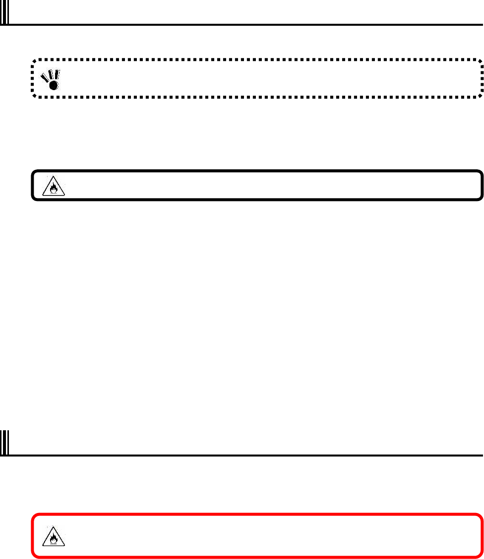
156
6.7 CARRIAGE AND STORAGE OF N22A
Follow the procedure below if N22A will be carried or stored.
1 Turn off the power of N22A.
2 Disconnect the AC adapter from the mating receptacle.
3 Remove all cables connected to N22A.
4 Remove the battery.
5 Package N22A securely so that it may neither damaged nor subjected to shocks and
vibrations.
Storage of N22A
Remove the battery from N22A if it will be stored for a long period.
Do not store the battery in a place where the temperature may exceed 60ºC to
prevent it from being deteriorated.
Store the battery in the following temperature ranges:
-20 to 60ºC in storage for a month or shorter
-20 to 45ºC in storage for three months or shorter
-20 to 20ºC in storage for a year or shorter
Do not leave the battery for three months or longer without recharging.
6.8 DISPOSAL OF DEVICES
For the disposal of N22A, hard disk drives and options, contact your service representative.
See “Recycling Batteries” in “Chapter 6 Maintenance” for the battery.
Back up important data stored in the hard disk.
Close all the covers during transportation.
To pull out a cord, be sure to hold the plug. Pulling a cord for removal may cause
disconnection and further fire to occur.
Neither put the battery close to fire nor soak it with water. Failure to follow this instruction may
cause the battery to fire, fume or explode.

157
Maintenance
THIS PAGE INTENTIONALLY LEFT BLANK.
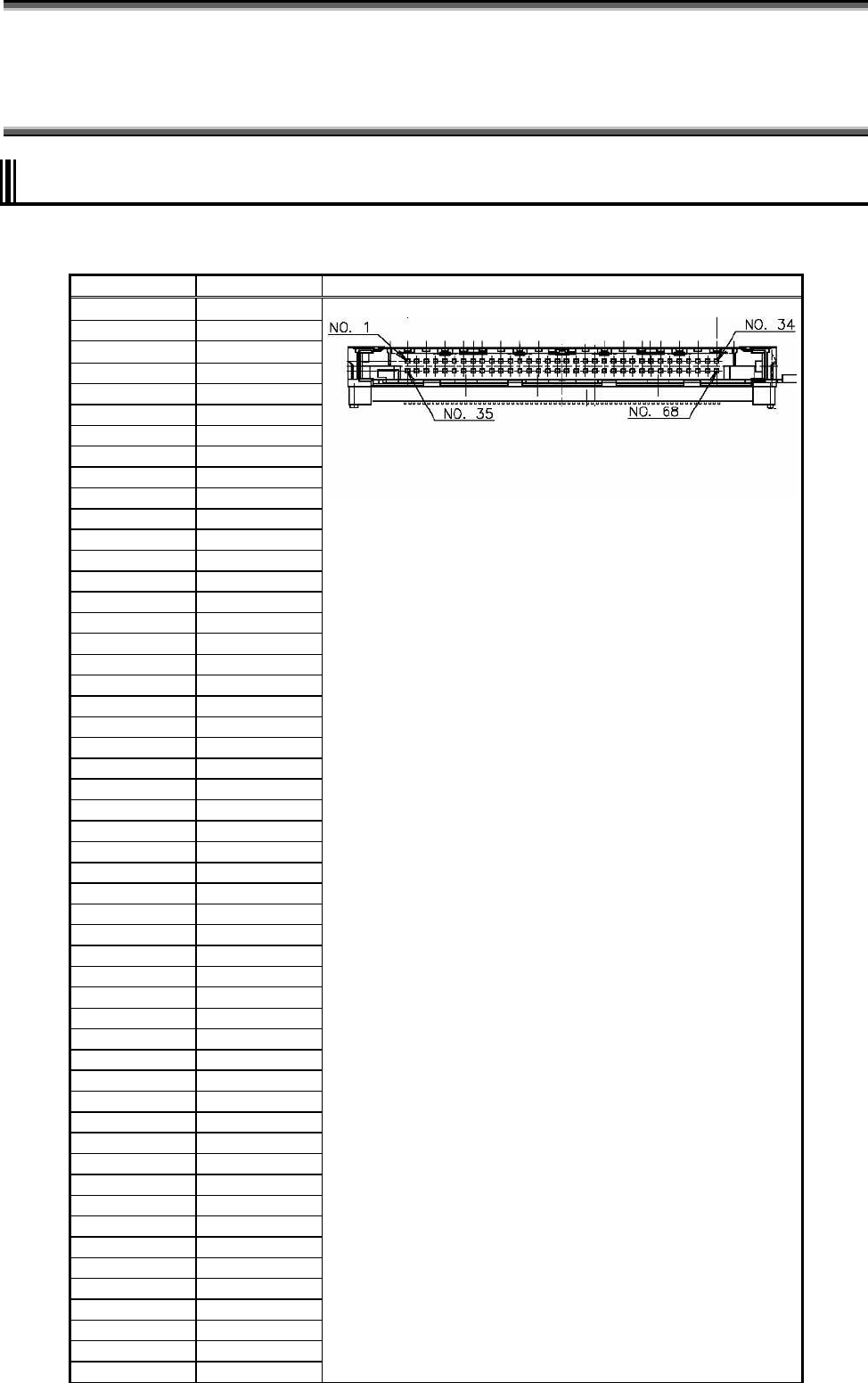
158
Chapter 7 Appendices
7.1 I/O INTERFACES
(1) PCMCIA interface
Connector: 68-pin card slot
Pin number Signal name Pin alignment
1 GND
2 CADATA<3>
3 CADATA<4>
4 CADATA<5>
5 CADATA<6>
6 CADATA<7>
7 CE1#
8 CADR<10>
9 OE#
10 CADR<11>
11 CADR<9>
12 CADR<8>
13 CADR<13>
14 CADR<14>
15 WE#
16 IREQ#
17 CAVCC
18 CAVPP
19 CADR<16>
20 CADR<15>
21 CADR<12>
22 CADR<7>
23 CADR<6>
24 CADR<5>
25 CADR<4>
26 CADR<3>
27 CADR<2>
28 CADR<1>
29 CADR<0>
30 CADATA<0>
31 CADATA<1>
32 CADATA<2>
33 IOIS16#
34 GND
35 GND
36 CD1#
37 CADATA<11>
38 CADATA<12>
39 CADATA<13>
40 CADATA<14>
41 CADATA<15>
42 CE2#
43 VS1
44 IORD#
45 IOWR#
46 CADR<17>
47 CADR<18>
48 CADR<19>
49 CADR<20>
50 CADR<21>
51 CAVCC
52 CAVPP
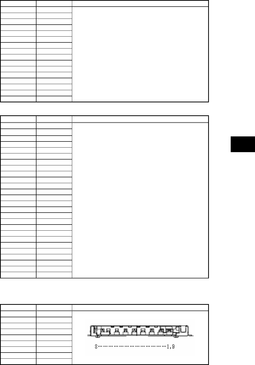
159
Appendices
Pin number Signal name Pin alignment
53 CADR<22>
54 CADR<23>
55 CADR<24>
56 CADR<25>
57 VS2
58 RESET
59 WAIT#
60 INPACK#
61 REG#
62 SPKR#
63 CHSTS#
64 CADATA<8>
65 CADATA<9>
66 CADATA<10>
67 CD2#
68 GND
(2) Express card interface
Pin number Signal name Pin alignment
1 GND
2 USBD-
3 USBD+
4 CPUSB#
5 RESERVED
6 RESERVED
7 SMBCLK
8 SMBDATA
9 +1.5V
10 +1.5V
11 WAKE#
12 +3.3VAUX
13 PERST#
14 +3.3V
15 +3.3V
16 CLKREQ#
17 CPPE#
18 REFCLK-
19 REFCLK+
20 GND
21 PERn0
22 PERp0
23 GND
24 PETn0
25 PETp0
26 GND
(3) SD interface
Connector: SD-slot 12-pin connector (female)
Pin number Signal name Pin alignment
1 CD/DATA3
2 CMD
3 GND
4 MEDIA_3V
5 CLK
6 GND
7 DATA0
8 DATA1
9 DATA2
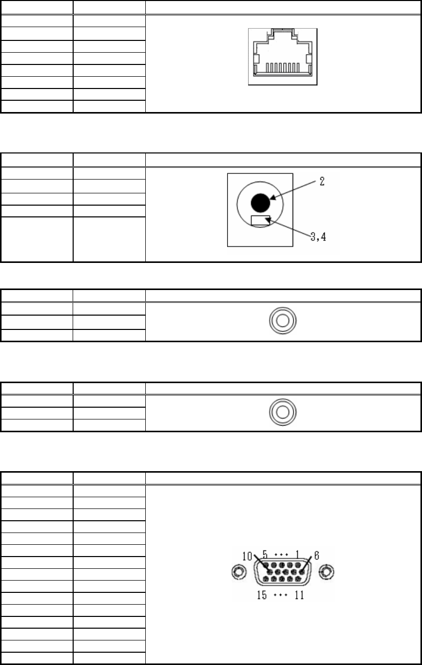
160
(4) LAN interface (1000BASE-T)
Connector: RJ45
Pin number Signal name Pin alignment
1 LA_TRD0+
2 LA_TRD0-
3 LA_TRD1+
4 LA_TRD2+
5 LA_TRD2-
6 LA_TRD1-
7 LA_TRD3+
8 LA_TRD3-
8 • • • 1
(5) DC plug jack
Connector: RJ11
Pin number Signal name Pin alignment
- -
2 ADP-IN
3 AC-GND
4 AC-GND
(6) Headphone output interface
Pin number Signal name Pin alignment
1 AGND
2 LEFT
3 RIGHT
(7) Microphone input interface
Connector: Mini jack (female)
Pin number Signal name Pin alignment
1 AGND
2 LEFT
3 RIGHT
(8) Analog RGB interface
Connector: SD-sub 15-pin connector (female)
Pin number Signal name Pin alignment
1 RED
2 GREEN
3 BLUE
4 NC
5 GND
6 GND
7 GND
8 GND
9 VP50
10 GND
11 NC
12 DDCA
13 HSYNC
14 VSYNC
15 DDCL
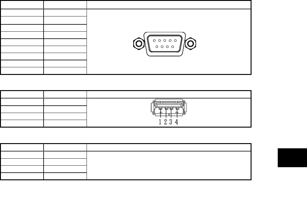
161
Appendices
1 • • • 5
6 • • 9
(9) Serial interface (COM1)
Connector: D-sub 9-pin connector (male)
Pin number Signal name Pin alignment
1 DCD
2 RXD
3 TXD
4 DTR
5 GND
6 DSR
7 RTS
8 CTS
9 RI
(10) USB interface (USB 1/2/3)
Pin number Signal name Pin alignment
1 +5V
2 D-
3 D+
4 GND
(11) IEEE1394 interface
Pin number Signal name Pin alignment
1 TPB-
2 TPB+
3 TPA-
4 TPA+
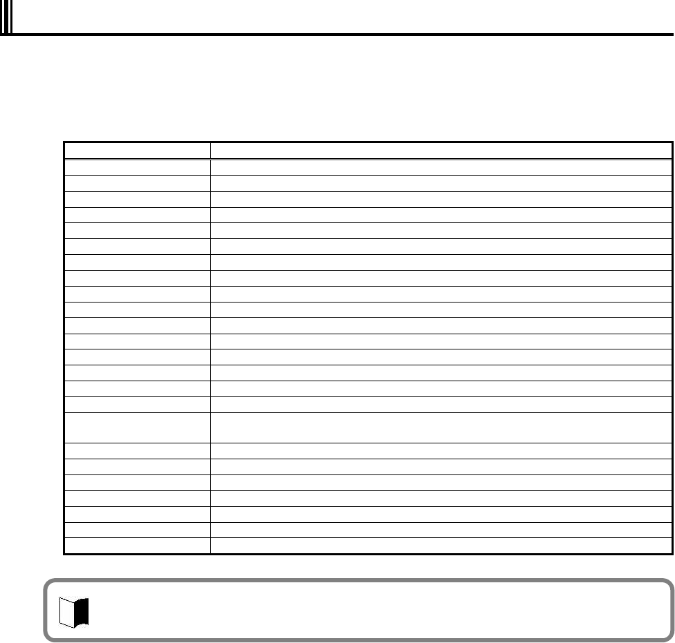
162
7.2 INTERRUPT LEVELS
The table below lists interrupt levels. Interrupt levels 0 to 23 are assigned. A smaller interrupt
level has a higher priority.
List of assignment levels
Interrupt level Setting at shipment from factory
IRQ00 Counter/timer
IRQ01 Keyboard (PS/2)
IRQ02 Interrupt controller
IRQ03 COM 2
IRQ04 COM 1 (serial port)
IRQ05 (Not used)
IRQ06 (Not used)
IRQ07 (Not used)
IRQ08 System CMOS/realtime clock
IRQ09 Microsoft ACPI-Compliant System
IRQ10 SMBus controller
IRQ11 (Not used)
IRQ12 Touch pad
IRQ13 Math coprocessor
IRQ14 Primary IDE
IRQ15 Secondary IDE
IRQ16 Express Card/PC card bus controller/USB UHCI4 Internal GA, PCI Express Root
Port 2
IRQ17 Wireless LAN/IEEE1394 PCI Express Root Port1
IRQ18 EHCI2/USB UHCI2/SD card
IRQ19 USB UHCI1/SATAAHCI controller
IRQ20 Internal LAN
IRQ21 USB UHCI5
IRQ22 HDA Sound
IRQ23 USB UHCI0/USB EHCI
Assignment may vary depending on whether the device is used or not by the peripheral device
setting of BIOS.
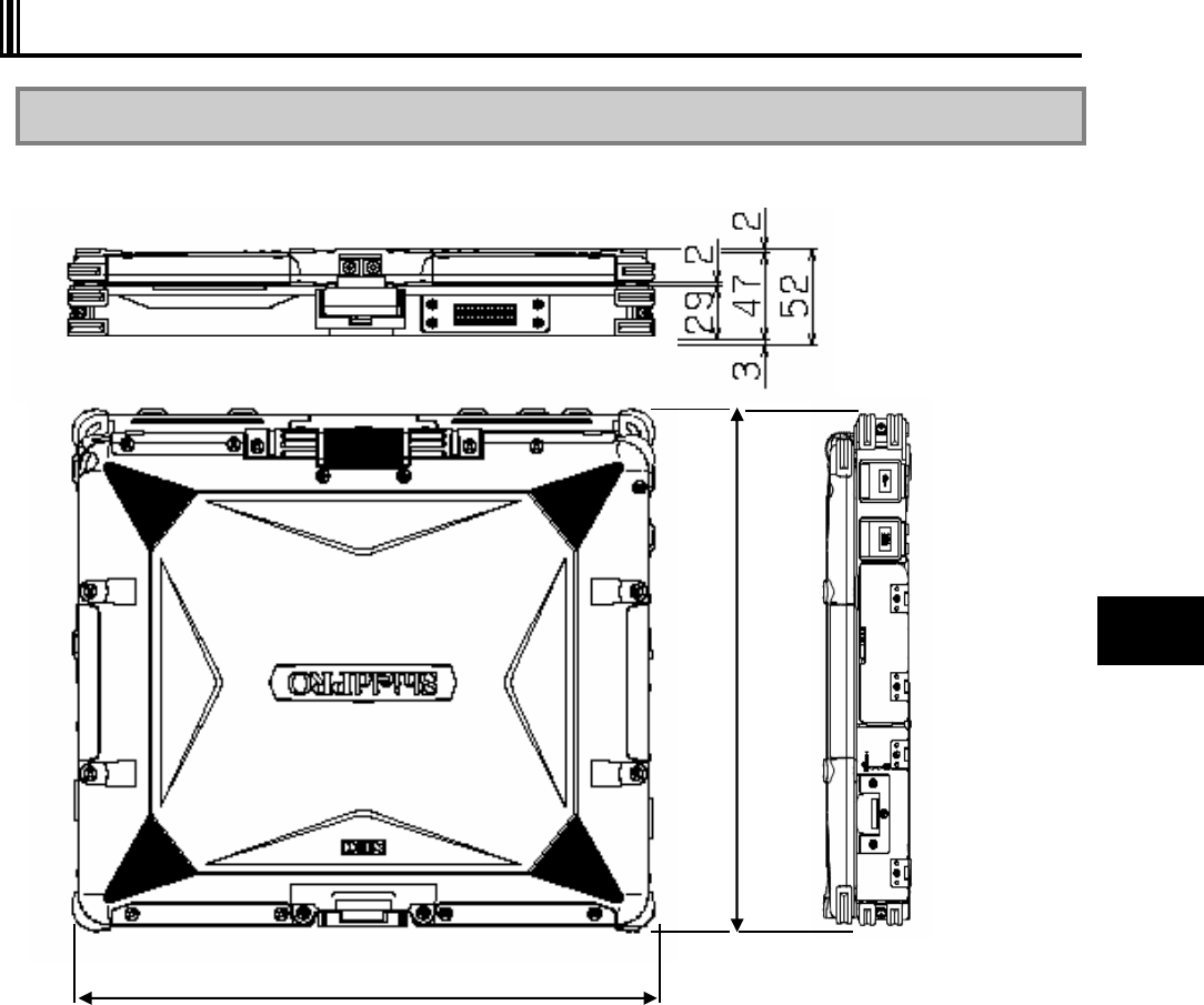
163
Appendices
7.3 OUTSIDE DIMENSION
7.3.1 N22A
(1) Body
298.6
260.4
(295.4 excluding projections and bumper)
(245.5 excluding projections and bumper)
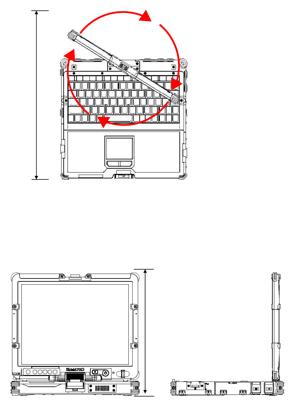
164
* Excluding projections (including rubber feet and protect rubbers at 4 corners)
[Rotation of LCD display panel]
389.8
[Body with LCD display panel made upright (node type)]
283.6
Unit: mm
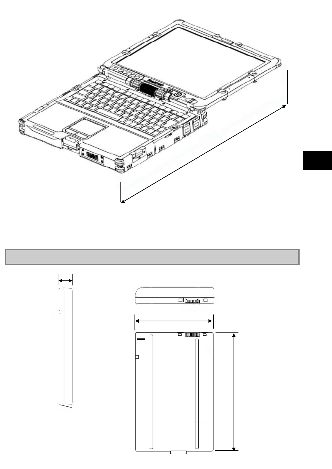
165
Appendices
* Excluding projections (including rubber feet and protect rubbers at 4 corners)
7.3.2 Spare Battery (FC-BP01N, FC-BP01N/W, FC-BP01N/L)
483.4
20.5
145.1
100.69
Unit: mm
Unit: mm
Weight: about 0.33 kg(FC-BP01N)
about 0.33 kg(FC-BP01N/W)
about 0.21 kg(FC-BP01N/L)
[Body with LCD display panel taken down]
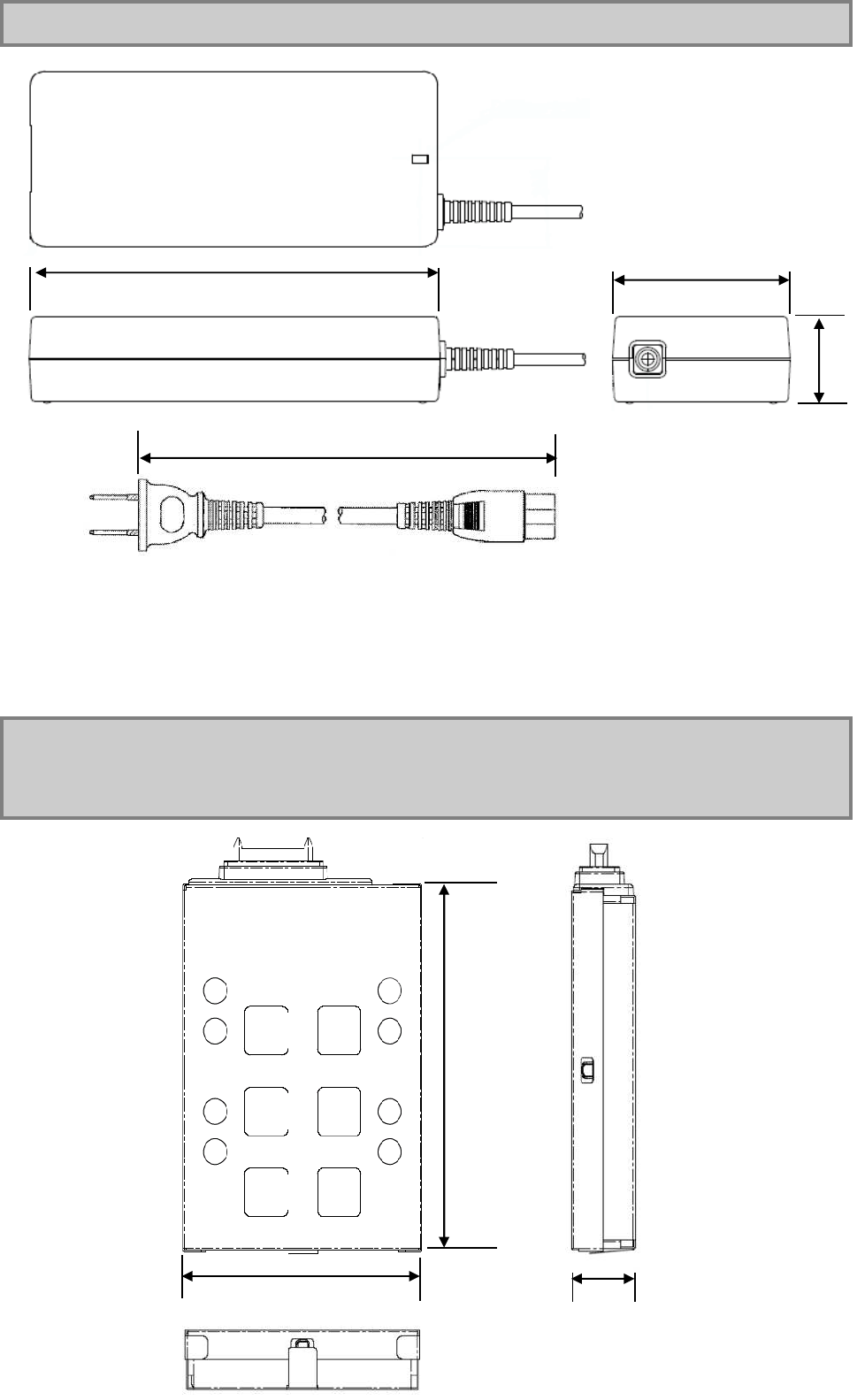
166
7.3.3 AC Adapter (FC-AA01N)
7.3.4 Hard Disk Drive (Standard HDD:FC-HD80KN-S,
Wide Temperature HDD:FC-HD40KN-S)/
Silicon Disk Drive (FC-SD20KN-S)
AC
cabl
e
leng
th
Abo
ut
1.8
m
Pow
er
cord
leng
th
Abo
ut 2
m
Unit: mm
Weight: about 0.46 kg
63
±
0.5
140
±
0.5
128.3
82.2
Unit: mm
Weight: about 0.12Kg
(FC-HD80KN-S)
about 0.12Kg
(FC-HD40KN-S)
about 0.12Kg
(FC-SD20KN-S)
2,000
±
100
20.5
* Excluding projections
30.5
±
0.5

167
Appendices
Problem check sheet
When making an inquiry, you will be asked the configuration of the product in use and specific
conditions of the problem.
Before inquiring, complete each item of this sheet, which will lead to a prompt and appropriate
response. We recommend using this sheet.
Problem Check Sheet 1 Configuration of device
Hardware
Main unit
Model number
(shown on the
warranty) FC-N22A/
Serial number
(warranty
number) S
Memory capacity MB (MegaByte)
Hard disk
capacity GB (GigaByte)
Available hard
disk space
GB (GigaByte)
MB (MegaByte)
To check the hard disk capacity and available space, click [My computer] and right-click the
hard disk icon followed by [Properties] in the menu shown. The capacity and space will be
shown.
Peripheral
devices Product name and model name (manufacture name)
Expansion
memory
Display
Printer
Expanded hard
disk drive
Network board
PC card
Other peripheral
device(s)

168
Software
Version of OS
□ Windows XP Professional (ServicePack )
Application(s) running while the failure occurred
Problem Check Sheet 2 Specific failure details
What failed? Describe the failure.
Did any error messages or numbers appear on the screen?
If any appeared, write the message(s) or the number(s).
When does the failure occur?
Describe the situation when the failure occurred, such as the names of all applications
running and the operation status.
□ At every start-up.
□ Every time the application is started.
□ When a specific operation is performed.
□ For the first time.
Decribe what you noticed, if anything.
Describe when you noticed the failure and whether anything unusual happened then.
Problem Check Sheet 3 Configuration of device
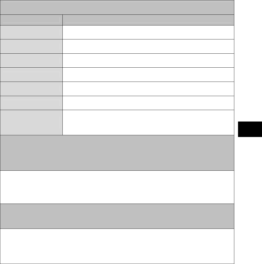
169
Appendices
NEC will confirm the following when receiving your repair request.
To eliminate any problem related to repair, complete all of the following items.
If the configuration of peripheral devices for repair is different from that written in Problem
Check Sheet 1, enter the following.
Peripheral devices Product name and model name (manufacture name)
Expansion memory
Display
Printer
Expanded hard disk drive
Network board
PC card
Other peripheral
device(s)
Software may be initialized (including replacement of the hard disk) during repair. Do you
agree with software initialization?
If you do not agree with initialization, the device may not be repaired.
Be sure to backup the data you created in the hard disk before requesting a repair, regardless of whether you agree with
initialization. (For how to backup, see Windows Help.)
□ Agree with initialization
□ Do not agree with initialization
If the system setting (BIOS setting) has been changed, describe what was changed.
After repair, the BIOS setting will be returned to the factory setting.
If you have changed the BIOS setting, be sure to record your changes.

170
INDEX
A
AC adapter············································10
APPLICATION··········································
B
BATTERY ·············································33
BIOS ·····················································59
BIOS SETUP UTILITY··························59
Bluetooth···················································
C
Checking Remaining Battery Level·······34
COMMUNICATION FEATURE·············43
Connecting External Monitor·················31
Convertible type······································2
D
Dust-proof and drip-proof······················16
F
FA Environment····································16
FC button··············································24
FINGERPRINT SENSOR ·····················42
Floppy disk············································16
H
HARD DISK DRIVE ······························53
Hard disk password ······························89
Hard Disk Security································73
HDD Thermal Sensor····························79
Hot Keys ···············································22
I
I/O Lock ················································76
Initializing Battery··································37
K
KEYBOARD··············································
Keyboard with backlight························23
L
LCD display ··········································12
M
MAINTENANCE········································
MEMORY CARD ······································
P
Pause state···········································13
PC CARD/EXPRESS CARD·················38
PCI Configuration ·································66
Power lamp···········································14
Power Saving Features ························13
Primary Master ·····································65
Processor Settings································65
R
Remote power-on feature ·····················46
Resume ················································15
S
Safe mode ··········································120
SD Card················································40
Security·················································71
SECURITY MENU ····································
SILICON DISK DRIVE ··························53
SSIDs (network names)························51
Supervisor password ····························71
Suspend (standby) state·······················13
T
TABLET BUTTONS······························19
Tablet mode··········································12
TOUCH PAD·············································
TOUCH PANEL ········································
U
User password··········································
W
WEP feature ·········································51
Wide temperature type ·························53
Wireless LAN········································47

171
Appendices

NEC Factory Computer
FC-NOTE Series
N22A
User’s Manual
Ver. 1 May 2008
AM1
-
000859
-
001