NETIS SYSTEMS WF2301RT 150Mbps Wireless-N Outdoor Access Point User Manual netis WF 2301
NETIS SYSTEMS CO., LTD. 150Mbps Wireless-N Outdoor Access Point netis WF 2301
user manual
netis 150Mbps Wireless-N
Outdoor Access Point
Quick Installation Guide
WF-2301
V1.1.01
2012-02-08
Package Contents
The following items should be found in your package
150Mbps Wireless-N Outdoor AP
PoE Adapter
Quick Installation Guide
Please make sure that the package contains the above items, if any of the listed items are damaged
or missing, please contact with your distributor.
Before You Begin
Minimum Requirements:
Broadband Internet access service (DSL / Cable / Ethernet)
Internet Explorer 5.0 or higher for Web configuration
802.11n,802.11g or 802.11b compliant wireless adapters (for wireless connection)
Windows 98/2000/XP/2003/Vista or higher operating system
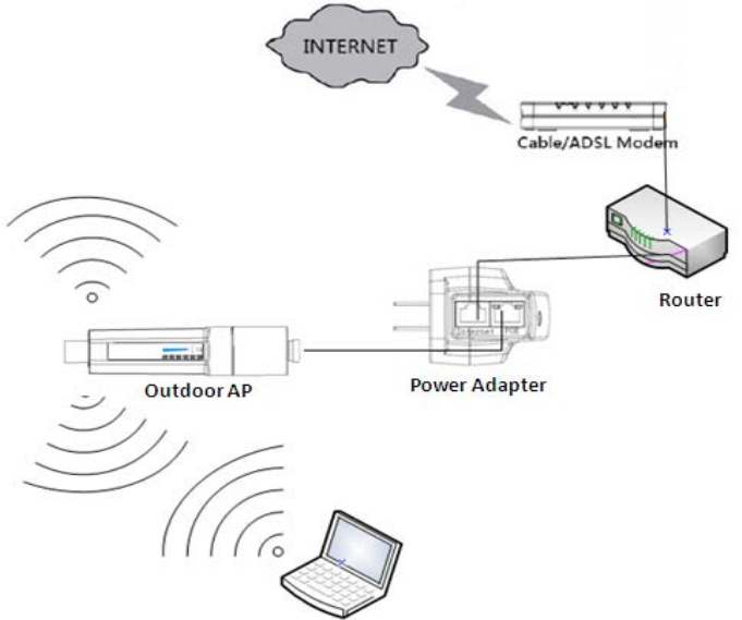
1. Hardware Installation Procedures
The procedures to install the Wireless-N AP please refer to Figure 1-1
Figure 1-1
Step 1 connecting Cable/ADSL Modem to the WAN port.
Attach one end of an Ethernet cable to your modem’s Ethernet port, and the other end to one
of the WAN ports of your router.
Step 2 connecting the power adapter.
Attach one end of an Ethernet cable to the Internet access router LAN port, the other end to
the Internet port of power adapter. Then plug the Power Adapter into an AC outlet.
Step 3 connecting the 150Mpbs outdoor adapter.
Connect another Ethernet cable from your POE port of the power adapter to the LAN port of
150Mbps outdoor AP.
Step 4 Power on the following devices in this order:
Cable/ADSL modem, Router.
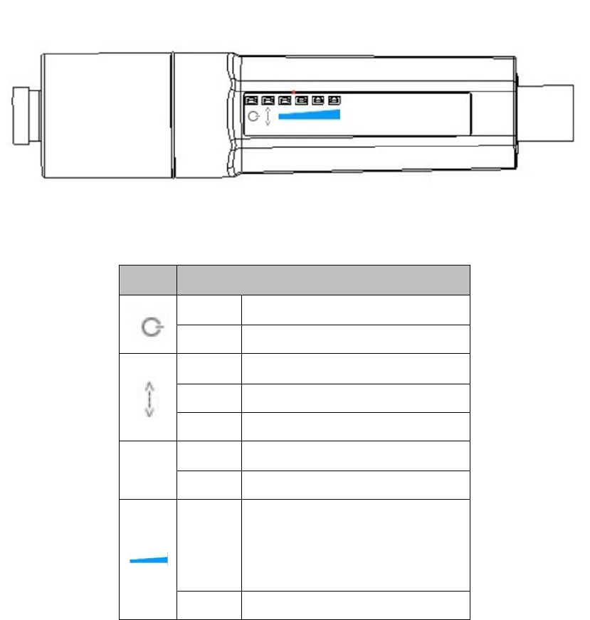
2. LED Indicators
Figure 2-1
LEDFunction
ONPoweron
OffPoweroff
OnConnectionnormal
OffAbnormal
Flashing Datatransmitting
OnPowersupplynormal
POE
OffAbnormal
Flashing
4lightsignalstrengthabove75%
3lightsignalstrengthmedium
Lessthan2lightsignalstrengthis
weak.
OffNosignal
3. Configure computer
3.1. Windows 98/Me
1. Go to Start Settings Control Panel.
2. Find and double-click the Network icon. The Network dialog box appears.
3. Click the Configuration label and ensure that you have network card.
4. Select TCP/IP. If TCP/IP appears more than once, please select the item that has an arrow “”
pointing to the network card installed on your computer. DO NOT choose the instance of TCP/IP
with the words “Dial Up Adapter” beside it.
5. Click Properties. The TCP/IP Properties dialog box appears.
6. Ensure the Obtain IP Address Automatically is checked.
7. From the WINS Configuration dialog box, Ensure that Disable WINS Resolution is checked.
8. From the Gateway dialog box, remove all entries from the Installed gateways by selecting them
and clicking Remove.
9. From the DNS Configuration dialog box, remove all entries from the DNS Server Search Order
box by selecting them and clicking Remove. Remove all entries from the Domain Suffix Search
Order box by selecting them and clicking Remove. Click Disable DNS.
10. Click OK, back to Network Configuration dialog box
11. Click OK, if prompted to restart, click YES.
3.2. Windows 2000
Please follow the steps below to setup your computer:
1. Go to Start Settings Control Panel
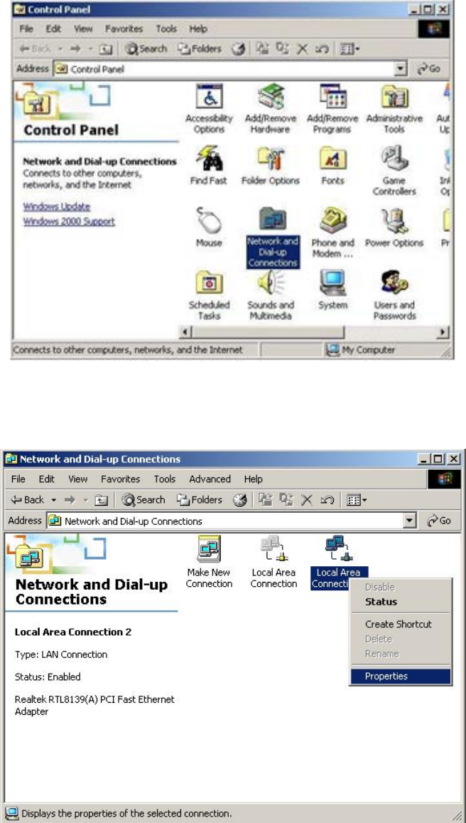
Figure 3-1
2. Double click the icon Network and Dial-up Connections
3. Highlight the icon Local Area Connection, right click your mouse, and click Properties
Figure 3-2
4. Highlight Internet Protocol (TCP/IP), and then press Properties button
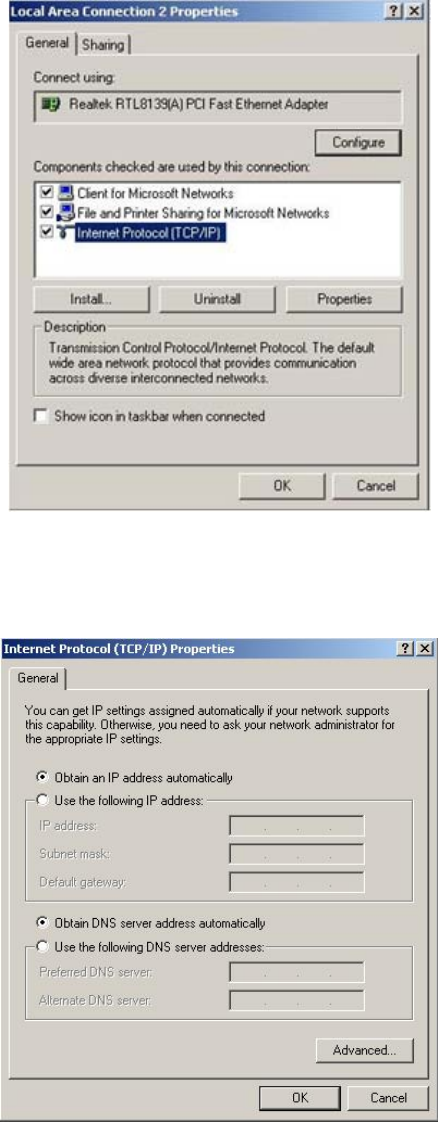
Figure 3-3
5. Choose Obtain an IP address automatically and Obtain DNS server address automatically, and
then press OK to close the Internet Protocol (TCP/IP) Properties window
Figure 3-4
6. Press OK to close the Local Area Connection Properties window
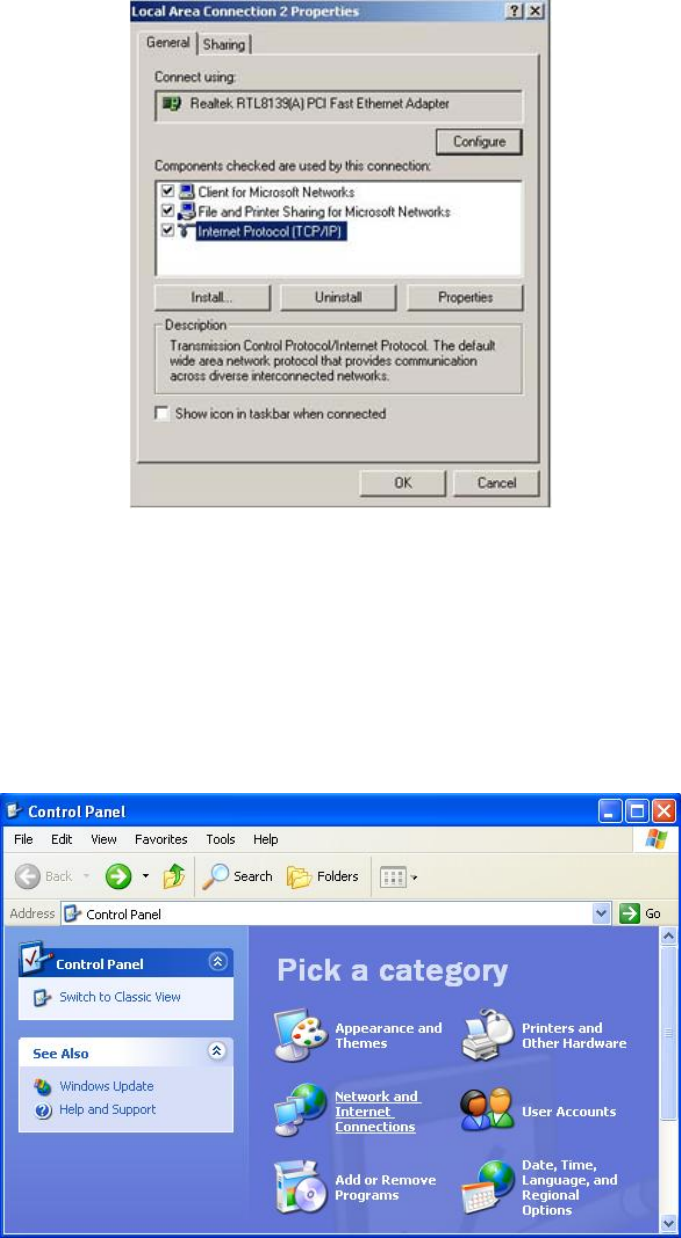
Figure 3-5
3.3. Windows XP
Please follow the steps below to setup your computer:
1. Go to Start Settings Control Panel
2. Click Network and Internet Connections
Figure 3-6
3. Click Network Connections
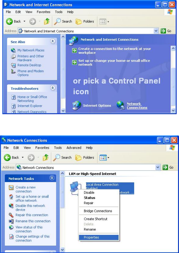
Figure 3-7
4. Highlight the icon Local Area Connection, right click your mouse, and click Properties
Figure 3-8
5. Highlight Internet Protocol (TCP/IP), and then press Properties button
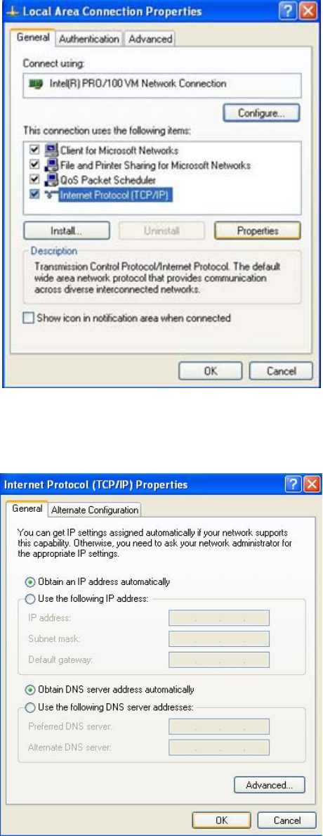
Figure 3-9
6. Choose Obtain an IP address automatically and Obtain DNS server address automatically, and
then press OK to close the Internet Protocol (TCP/IP) Properties window
Figure 3-10
7. Press OK to close the Local Area Connection Properties window
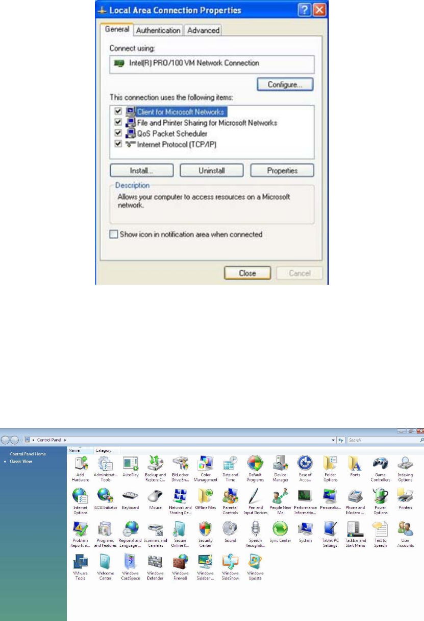
Figure 3-11
3.4. Windows Vista
Please follow the steps below to setup your computer:
1. Go to Start Settings Control Panel
2. Click Network and Sharing Center
Figure 3-12
3. Click Manage Network Connections
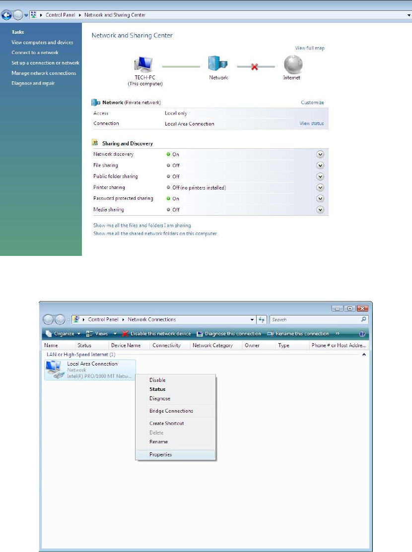
Figure 3-13
4. Highlight the icon Local Area Connection, right click your mouse, and click Properties
Figure 3-14
5. Highlight Internet Protocol Version 4 (TCP/IP) and then press Properties button
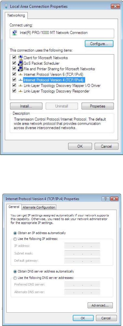
Figure 3-15
6. Choose Obtain an IP address automatically and Obtain DNS server address automatically, and
then press OK to close the Internet Protocol (TCP/IP) Properties window
Figure 3-16
7. Press OK to close the Local Area Connection Properties window.
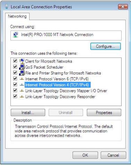
Figure 3-17
3.5. Windows 7
Please follow the steps blow to setup your computer:
1. Go to Start→ Control Panel→ Network and Internet.
2. Click Network and Sharing Center→ Change adapter settings.
3. Highlight the icon Local Area Connection, right click your mouse, and click Properties.
Highlight Internet Protocol version 4 (TCP/IPv4).
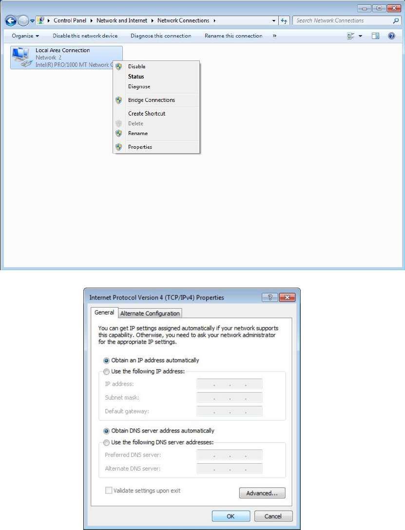
Figure 3-18
Figure 3-19
4. Choose Obtain an IP address automatically and Obtain DNS server address automatically,
and then press the OK to close the window.
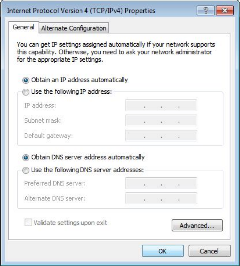
Figure 3-20
5. Press OK to close the Local Area Connection Properties window.
4. Checking Connection with the Adapter
After configuring the TCP/IP protocol, use the ping command to verify if the computer can
communicate with the Router. To execute the ping command, open the DOS window and Ping the
IP address of the 300Mbps Wireless-N Gigabit Router at the DOS prompt:
For Windows 98/Me: Start → Run. Type command and click OK.
For Windows 2000/XP: Start → Run. Type cmd and click OK.
For Windows Vista/7:Start→ Type cmd at the start search bar and press the Enter.

If the Command window returns something similar to the following:
C:\Documents and Settings\admin>ping 192.168.1.1
Pinging 192.168.1.1 with 32 bytes of data:
Reply from 192.168.1.1: bytes=32 time=1ms TTL=64
Reply from 192.168.1.1: bytes=32 time=1ms TTL=64
Reply from 192.168.1.1: bytes=32 time=1ms TTL=64
Reply from 192.168.1.1: bytes=32 time=1ms TTL=64
Ping statistics for 192.168.1.1:
Packets: Sent = 4, Received = 4, Lost = 0 (0% loss),
Approximate round trip times in milli-seconds:
Minimum = 0ms, Maximum = 0ms, Average = 0ms
Then the connection between the router and your computer has been successfully established.
If the computer fails to connect to the router, the Command window will return the
following:
C:\Documents and Settings\admin>ping 192.168.1.1
Pinging 192.168.1.1 with 32 bytes of data:
Request timed out.
Request timed out.
Request timed out.
Request timed out.
Ping statistics for 192.168.1.1:
Packets: Sent = 4, Received = 0, Lost = 4 (100% loss),
Verify your computer's network settings are correct and check the cable connection between
the router and the computer.
In order to make the whole network operate successfully, it is necessary to configure the
150Mbps AP through your computer has a WEB browser installed. Please follow up the steps
listed below.
5. Login
Open a web browser (Safari, Internet Explorer, etc.) on the computer you have just connected to
the router, type http://192.168.1.1 in the address bar, and press enter
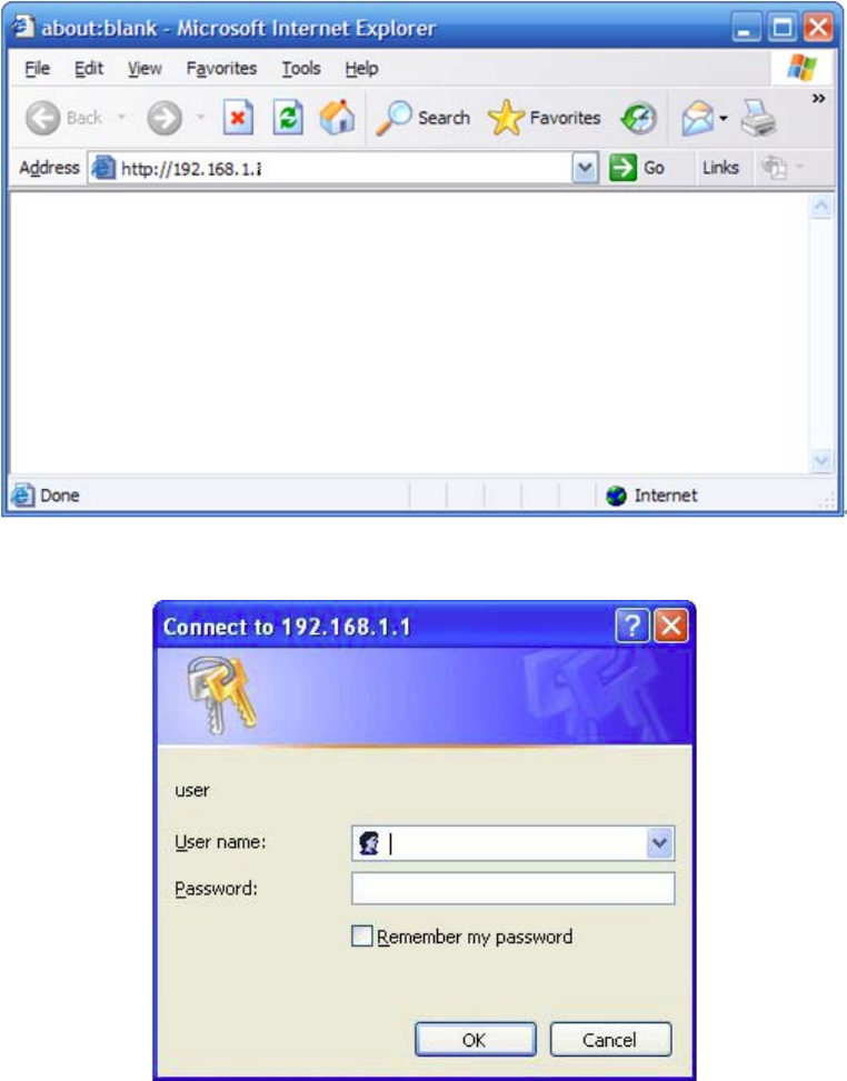
Figure 5-1
In the pop-up window, enter the user name guest and password guest and then click OK
Figure 5-2
6. Wireless AP Setup
6.1. Password Setup
The default username/password is guest/guest. To ensure the Router’s security, it is suggested that
you change the default password to one of your choice, here enter a new password and then
Re-enter it again to confirm your new password. Click “Save” button to save settings.
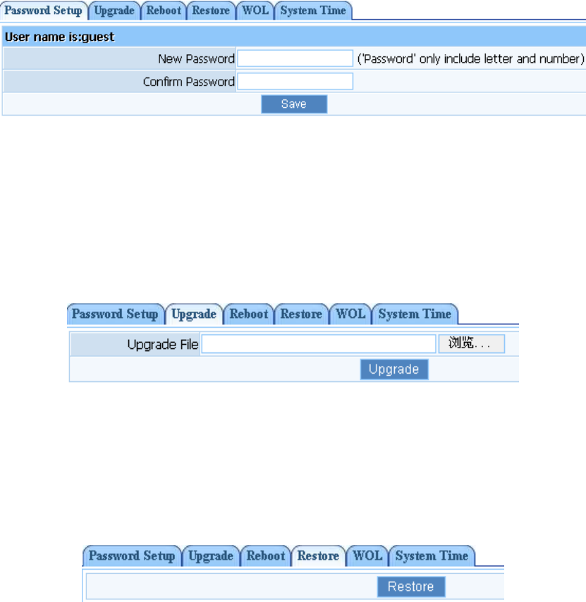
Figure 6-1
6.2. Upgrade
Click "Browse..."button and select a File to upgrade, after you have selected the appropriate file,
click "Upgrade" button to execute upgrade procedure. Do not cut off the power supply during the
process of upgrading.
Figure 6-2
6.3. Factory Defaults
Click "Restore" button, the Router will erase all of your settings and replace them with the factory
defaults, make sure you have backup current settings before click this button.
Figure 6-3
6.4. Wireless Security Settings
The item allows you to encrypt your wireless communication, and you can also protect your
wireless network from unauthorized user access. It supplies “WEP”, “WPA-PSK”, “WPA2-PSK”
and “WPA/WPA2-PSK” five different encryption modes.
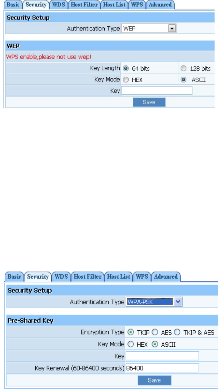
6.4.1. WEP
Figure 6-4
Key Length: There are two basic levels of WEP encryption, 64 bits and 128 bits, the more
bits password have, the better security wireless network is, at the same time the speed of
wireless is more slower.
Key Mode: If you select WEP to encrypt your data, choose the bits of password, it should be
64 bits or 128 bits. Then choose the format of password; it should be HEX or ASCII. The
valid character for HEX format should be numbers from 0 to 9 and letters from A to F. HEX
support mixed letter and number mode. And ASCII supports all characters that in keyboard.
Key Length description: when you select 64bits, you need to input 10 chars for HEX and 5
chars for ASCII, and when you select 128bits, you need to input 26 chars for HEX and 13
chars for ASCII.
Note: when the WPS is enabled, please not use WEP.
6.4.2. WPA-PSK
Figure 6-5
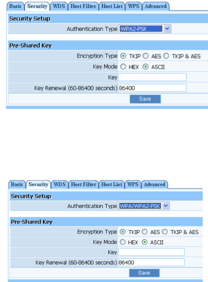
Encryption type: You can select the algorithm you want to use, TKIP, AES or TKIP&AES.
TKIP means “Temporal Key Integrity Protocol”, which incorporates Message Integrity Code
(MIC) to provide protection against hackers. AES, means “Advanced Encryption System”,
which utilizes a symmetric 128-Bit block data.
Key Renewal: you can configure the renewal time between 60 to 86400 seconds.
Key Length description: you need to input 8 to 63 ASCII characters no matter which type you
select.
6.4.3. WPA2-PSK
The WPA2-PSK is similar to WPA-PSK and with stronger encryption method than WPA-PSK,
using WPA2-PSK; you should input password (leave this value in the range of 8 to 63 characters)
and key renewal time (leave this value in the range of 60 to 86400 seconds).
Figure 6-6
6.4.4. WPA/WPA2-PSK
This item mixed WPA-PSK and WPA2-PSK mode, which provides higher security level; you can
configure it according with WPA-PSK or WPA2-PSK.
Figure 6-7
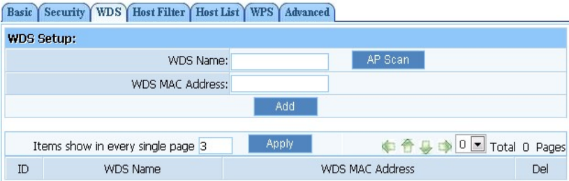
6.5. WDS Settings
If you have selected WDS or AP+WDS mode in Wireless Basic-Radio Mode, please do the
following configurations.
Figure 6-8
WDS Name: Give a description of your wireless bridge to tell apart.
WDS MAC Address: If the current working mode is “WDS” or “AP+WDS”, then you need
to configure wireless bridge configuration. Enter MAC address of remote access point, at the
same time the remote access point also need to configure to “WDS” or ”AP+WDS” mode.
Current WDS Information: It illustrates basic information of all wireless bridge that in
connection status, you may delete unnecessary bridge.
AP1:
Select radio mode is WDS or AP+WDS in wireless management-basic of AP1.
Click on ‘Wireless Management’- ‘AP Setup’- ‘Security’ and select and save None as
authentication type.
Click on ‘Wireless Management’- ‘AP Setup’- ‘Security’ and select and save None as WDS
authentication type or select a WDS security type, enter key and save.
Input WDS name (e.g.: default), input MAC address of AP2 (00-22-4f-bc-af-5d), click add,
then the record named default will appears in WDS list.
Select Channel is ‘Channel 6’in wireless management-basic of AP2.
AP2:
Select radio mode is WDS or AP+WDS in wireless management-basic of AP2.
The IP address of AP2 should be 192.168.1.x (1<x<255,e.g.: x=8).
Select ‘LAN setup’-‘DHCP server’ ,select disable DHCP server.
4. Input WDS name (e.g.: Default), input MAC address of AP1 (00-22-4f-cc-ae-f5), click add,
then the record named Default will appears in WDS list.
Select Channel is ‘Channel 6’in wireless management-basic of AP2.
Note: Before you setup WDS connection, please make sure that AP1 and AP2 is in the same
network, that is if the IP address of AP1 is 192.168.1.1, then the IP address of AP2 should be
192.168.1.x (1<x<255,e.g.: x=8).
FCC Statement
This equipment has been tested and found to comply with the limits for a Class B digital
device, pursuant to part 15 of the FCC rules. These limits are designed to provide reasonable
protection against harmful interference in a residential installation. This equipment generates,
uses and can radiate radio frequency energy and, if not installed and used in accordance with
the instructions, may cause harmful interference to radio communications. However, there is
no guarantee that interference will not occur in a particular installation. If this equipment does
cause harmful interference to radio or television reception, which can be determined by
turning the equipment off and on, the user is encouraged to try to correct the interference by
one or more of the following measures:
-Reorient or relocate the receiving antenna.
-Increase the separation between the equipment and receiver.
-Connect the equipment into an outlet on a circuit different from that to which the receiver is
connected.
-Consult the dealer or an experienced radio/TV technician for help.
To assure continued compliance, any changes or modifications not expressly approved by the
party responsible for compliance could void the user’s authority to operate this equipment.
(Example- use only shielded interface cables when connecting to computer or peripheral
devices)
FCC Radiation Exposure Statement
This equipment complies with FCC RF radiation exposure limits set forth for an uncontrolled
environment. This transmitter must not be co-located or operating in conjunction with any other
antenna or transmitter. This equipment should be installed and operated with a minimum
distance of 20 centimeters between the radiator and your body.
This equipment complies with Part 15 of the FCC Rules. Operation is subject to the following
two conditions:
(1) This device may not cause harmful interference, and
(2) This device must accept any interference received, including interference that may cause
undesired operation of the device