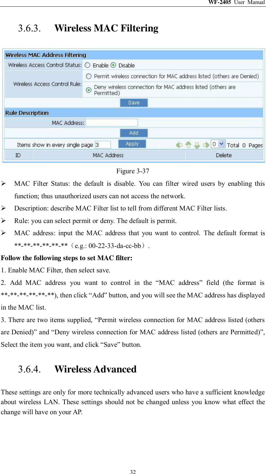
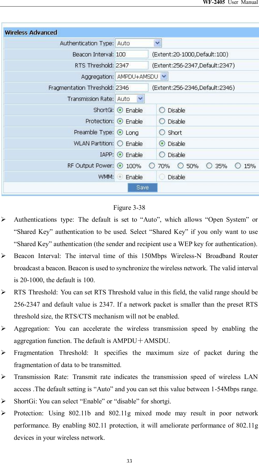
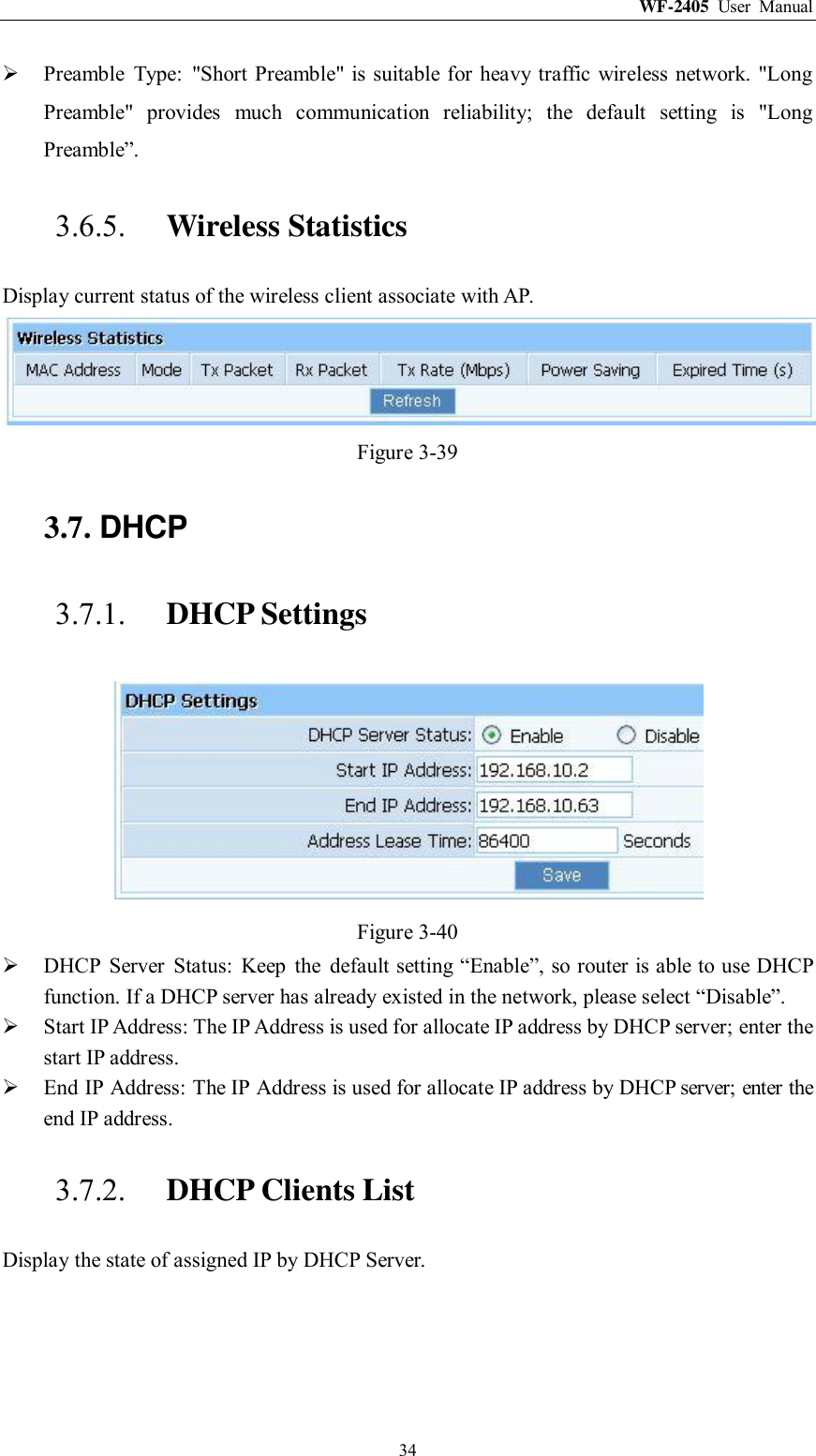
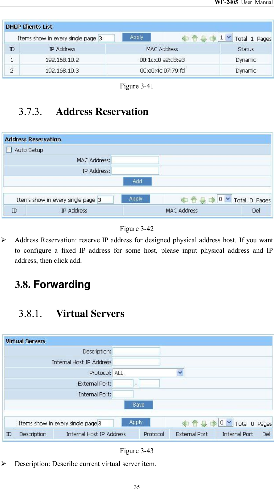
NETIS SYSTEMS WF2405R 150Mbps Wireless-N Mini Router/AP User Manual
NETIS SYSTEMS CO., LTD. 150Mbps Wireless-N Mini Router/AP
UserManual.wiki
>
NETIS SYSTEMS
>
WF2405R User Manual
User Manual
Navigation menu
Upload a User Manual
Namespaces
Wiki Guide
HTML
PDF
Info
Views
User Manual
Discussion / Help
Navigation
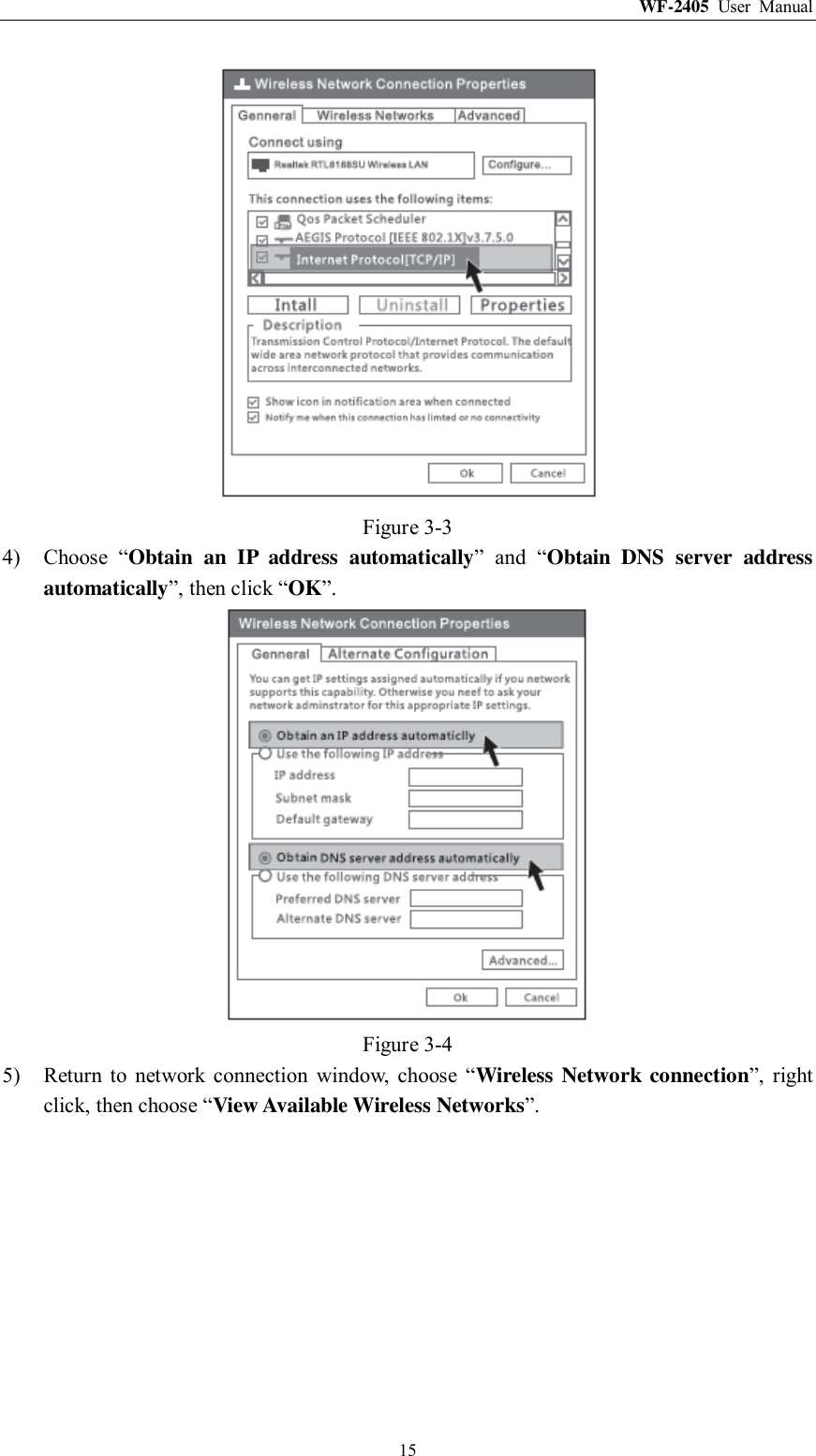
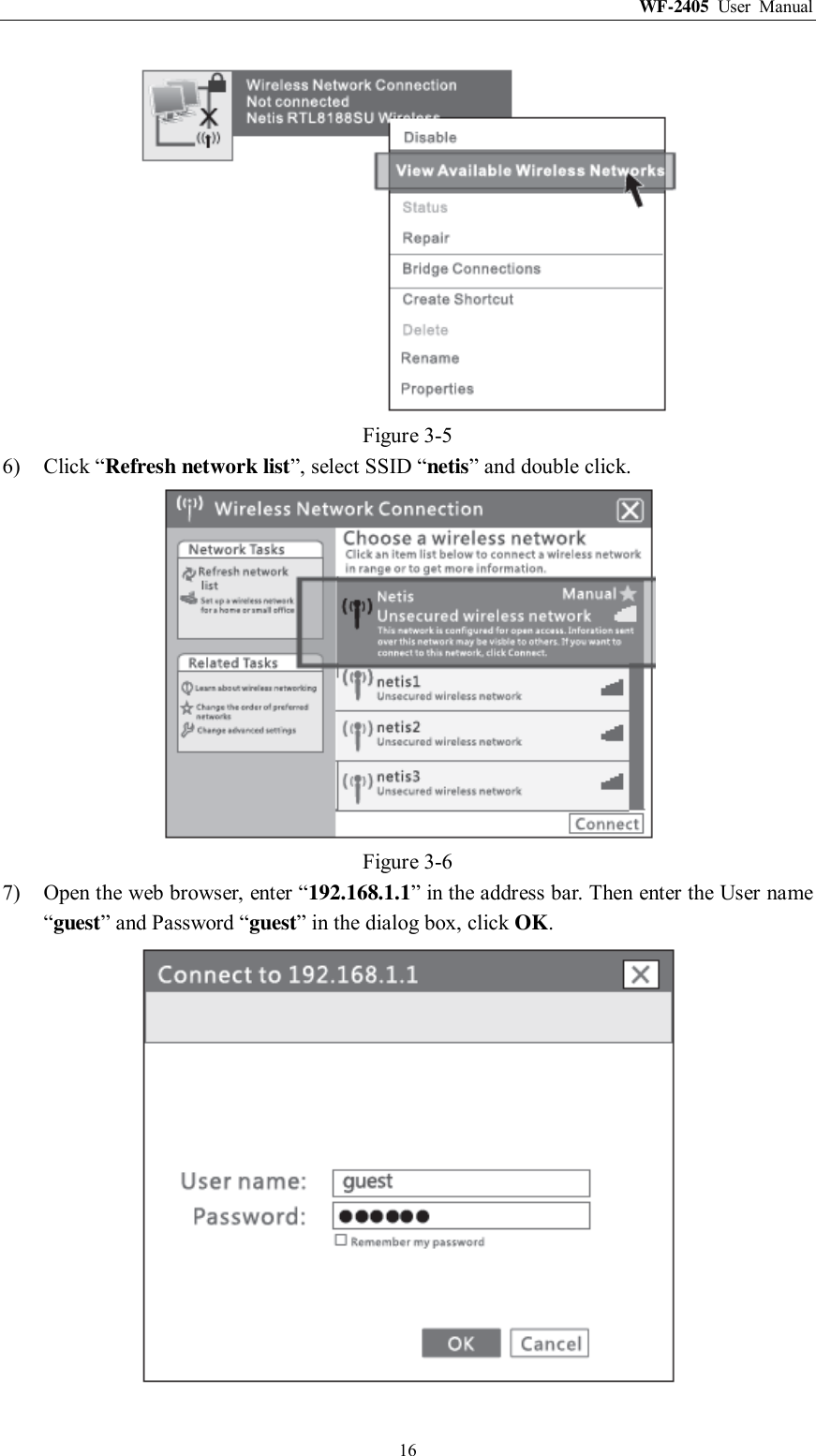
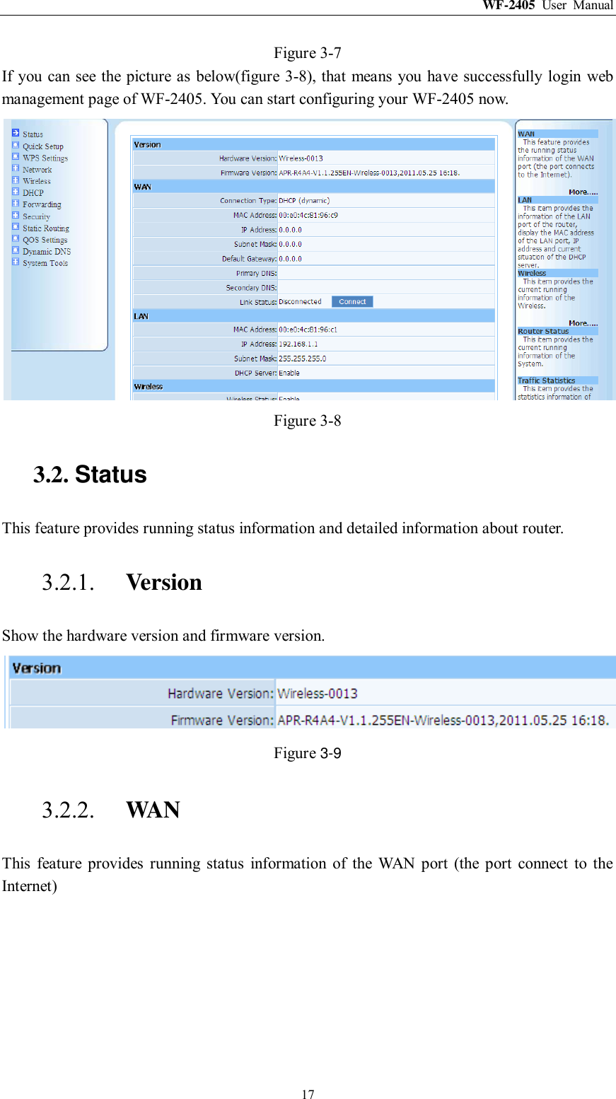
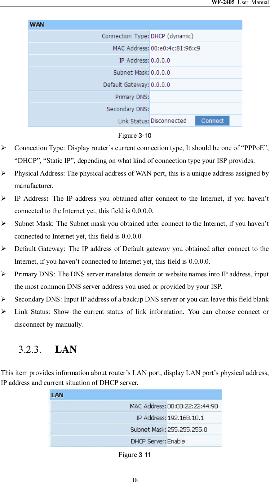
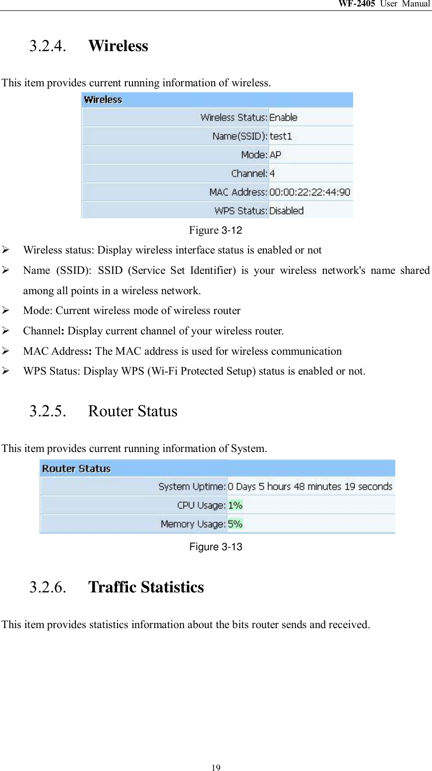
![WF-2405 User Manual 14 Figure 3-1 2) Select “Wireless Network connection”, right click, then choose “Properties”. Figure 3-2 3) Select “Internet Protocol[TCP/IP]”, double click.](https://usermanual.wiki/NETIS-SYSTEMS/WF2405R/User-Guide-1551133-Page-15.png)
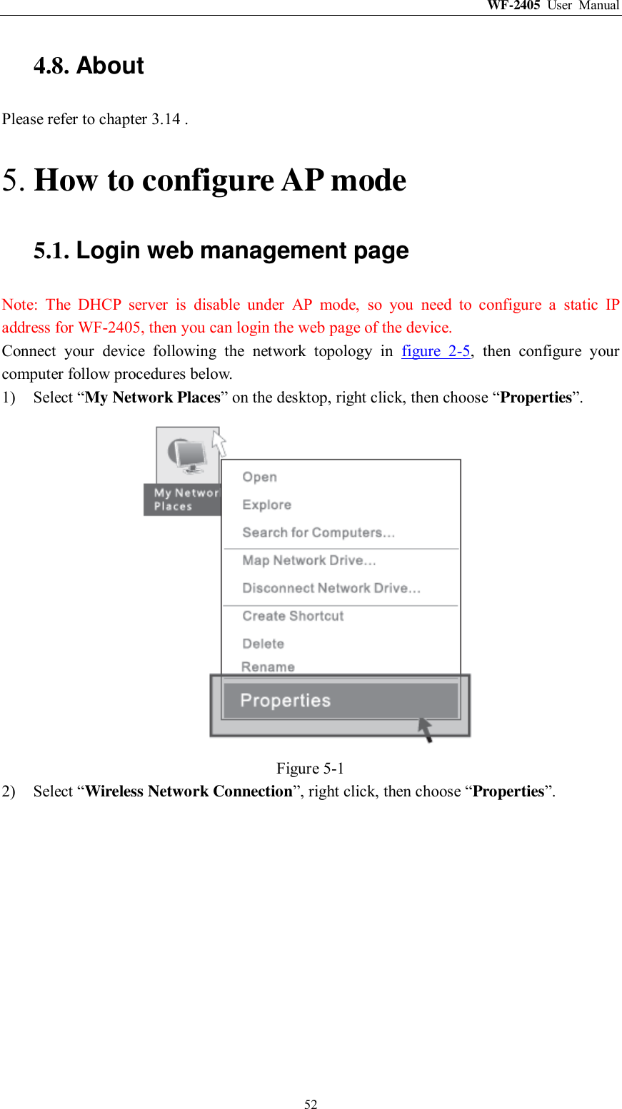
![WF-2405 User Manual 47 Figure 4-1 2) Select “Local Area connection”, right click, then choose “Properties”. Figure 4-2 3) Select “Internet Protocol[TCP/IP]”, double click.](https://usermanual.wiki/NETIS-SYSTEMS/WF2405R/User-Guide-1551133-Page-48.png)
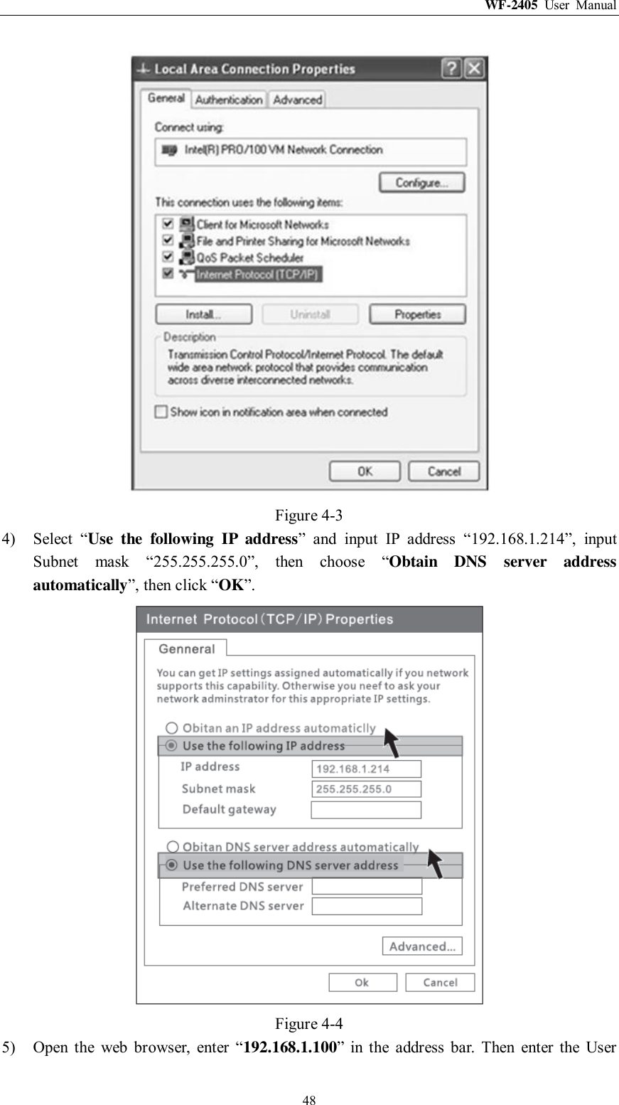
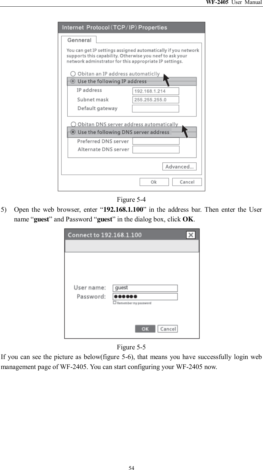
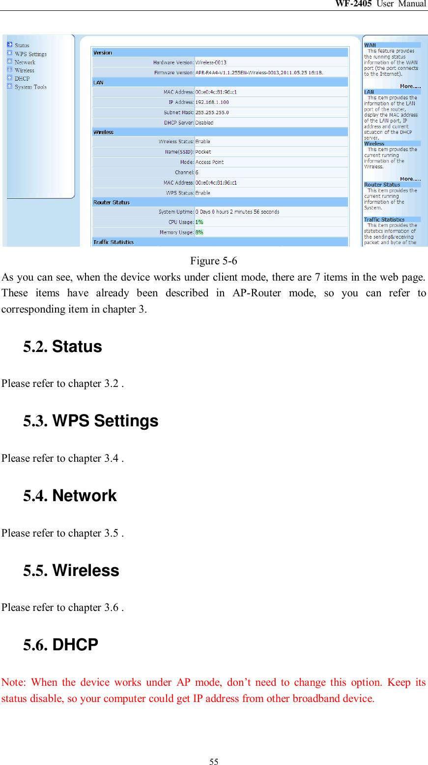
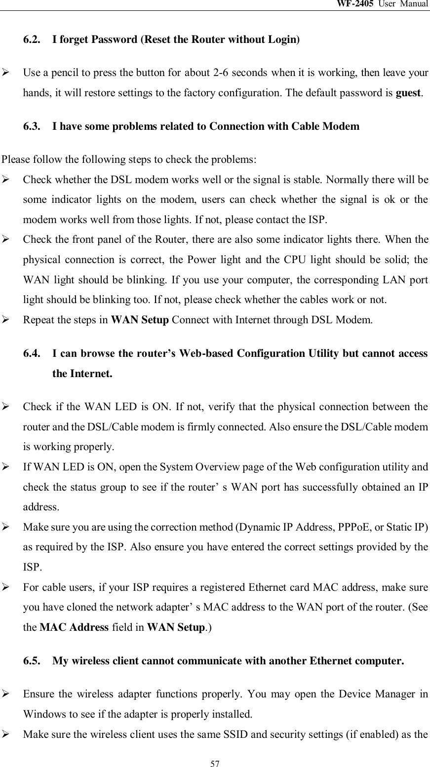
![WF-2405 User Manual 53 Figure 5-2 3) Select “Internet Protocol[TCP/IP]”, double click. Figure 5-3 4) Select “Use the following IP address” and input IP address “192.168.1.214”, input Subnet mask “255.255.255.0”, then choose “Obtain DNS server address automatically”, then click “OK”.](https://usermanual.wiki/NETIS-SYSTEMS/WF2405R/User-Guide-1551133-Page-54.png)