NETIS SYSTEMS WF2405R 150Mbps Wireless-N Mini Router/AP User Manual
NETIS SYSTEMS CO., LTD. 150Mbps Wireless-N Mini Router/AP
User Manual

WF-2405
User Manual
V1.1
2011-06-22

WF-2405 User Manual
1
Certification
FCC CE
FCC Statement
This equipment has been tested and found to comply with the limits for a Class B digital device,
pursuant to part 15 of the FCC rules. These limits are designed to provide reasonable protection
against harmful interference in a residential installation. This equipment generates, uses and can
radiate radio frequency energy and, if not installed and used in accordance with the instructions,
may cause harmful interference to radio communications. However, there is no guarantee that
interference will not occur in a particular installation. If this equipment does cause harmful
interference to radio or television reception, which can be determined by turning the equipment off
and on, the user is encouraged to try to correct the interference by one or more of the following
measures:
-Reorient or relocate the receiving antenna.
-Increase the separation between the equipment and receiver.
-Connect the equipment into an outlet on a circuit different from that to which the receiver is
connected.
-Consult the dealer or an experienced radio/TV technician for help.
To assure continued compliance, any changes or modifications not expressly approved by the party
responsible for compliance could void the user‟s authority to operate this equipment. (Example- use
only shielded interface cables when connecting to computer or peripheral devices)
FCC Radiation Exposure Statement
This equipment complies with FCC RF radiation exposure limits set forth for an uncontrolled
environment. This transmitter must not be co-located or operating in conjunction with any other
antenna or transmitter.
This equipment complies with Part 15 of the FCC Rules. Operation is subject to the following two
conditions:
(1) This device may not cause harmful interference, and
(2) This device must accept any interference received, including interference that may cause
undesired operation.
Caution!
The manufacturer is not responsible for any radio or TV interference caused by unauthorized
modifications to this equipment. Such modifications could void the user authority to operate the
equipment .The distance between user and product should be no less than 20cm.

WF-2405 User Manual
2
Package Contents
The following items should be found in your package:
WF-2405
Power adapter
Quick Installation Guide
CD-Rom
Ethernet cable
Make sure that the package contains above items. If any of the above items is missing or
damaged, please contact the store you bought this product from.
Brand and Copyright Announcement
Copyright © 2010 Netis Corporation.
All rights reserved
is a registered trademark of Netis Corporation. Other trademarks and trade
names may be used in this document to refer to either the entities claiming the marks and
names or their products.
Reproduction in any manner without the permission of Netis Corporation is strictly
forbidden
All the information in this document is subject to change without notice.
USA/Canada Technical Support
Phone: 1-866-71-network or 1-866-716-3896 (free in USA & Canada)
E-mail: usa_support@netis-systems.com

WF-2405 User Manual
3
Contents
CONTENTS ...................................................................................................................................... 3
1. INTRODUCTION .................................................................................................................... 6
1.1. PRODUCT OVERVIEW .......................................................................................................... 6
1.2. MAIN FEATURES ................................................................................................................. 6
1.3. SUPPORTING STANDARD AND PROTOCOL ............................................................................. 6
1.4. WORKING ENVIRONMENT ................................................................................................... 7
2. HARDWARE INSTALLATION .............................................................................................. 8
2.1. SYSTEM REQUIREMENT ...................................................................................................... 8
2.2. PANEL DEFINITION .............................................................................................................. 8
2.3. HOW TO RESTORE FACTORY CONFIGURATION ..................................................................... 10
2.4. HARDWARE INSTALLATION PROCEDURES ........................................................................... 10
2.4.1. AP-Router mode ...................................................................................................... 10
2.4.2. Client mode ............................................................................................................. 11
2.4.3. AP mode .................................................................................................................. 12
3. HOW TO CONFIGURE AP-ROUTER MODE .................................................................... 13
3.1. LOGIN WEB MANAGEMENT PAGE........................................................................................ 13
3.2. STATUS............................................................................................................................. 17
3.2.1. Version .................................................................................................................... 17
3.2.2. WAN ........................................................................................................................ 17
3.2.3. LAN......................................................................................................................... 18
3.2.4. Wireless ................................................................................................................... 19
3.2.5. Router Status ........................................................................................................... 19
3.2.6. Traffic Statistics ....................................................................................................... 19
3.3. QUICK SETUP ................................................................................................................... 20
3.3.1. DHCP (dynamic) ..................................................................................................... 20
3.3.2. PPPoE .................................................................................................................... 20
3.3.3. Static ....................................................................................................................... 21
3.3.4. Wireless Configuration ............................................................................................ 21
3.3.5. MAC Clone ............................................................................................................. 22
3.4. WPS SETTINGS................................................................................................................. 22
3.4.1. WPS Settings ........................................................................................................... 23
3.4.2. Add a New Device ................................................................................................... 23
3.4.3. WPS Configuration .................................................................................................. 23
3.5. NETWORK ........................................................................................................................ 24
3.5.1. WAN ........................................................................................................................ 24
3.5.1.1. Wired Access ................................................................................................................... 25
3.5.1.2. Wireless Access ................................................................................................................ 26
3.5.2. LAN......................................................................................................................... 27
3.5.3. MAC Clone ............................................................................................................. 27
3.5.4. IGMP Proxy ............................................................................................................ 27

WF-2405 User Manual
4
3.6. WIRELESS ........................................................................................................................ 28
3.6.1. Wireless Settings ...................................................................................................... 28
3.6.2. Wireless Security ..................................................................................................... 29
3.6.2.1. None ................................................................................................................................ 29
3.6.2.2. WEP ................................................................................................................................ 29
3.6.2.3. WPA-PSK ........................................................................................................................ 30
3.6.2.4. WPA2-PSK ...................................................................................................................... 30
3.6.2.5. WPA/WPA2-PSK ............................................................................................................. 31
3.6.3. Wireless MAC Filtering ........................................................................................... 32
3.6.4. Wireless Advanced ................................................................................................... 32
3.6.5. Wireless Statistics .................................................................................................... 34
3.7. DHCP .............................................................................................................................. 34
3.7.1. DHCP Settings ........................................................................................................ 34
3.7.2. DHCP Clients List ................................................................................................... 34
3.7.3. Address Reservation ................................................................................................ 35
3.8. FORWARDING ................................................................................................................... 35
3.8.1. Virtual Servers ......................................................................................................... 35
3.8.2. Port Triggering........................................................................................................ 36
3.8.3. DMZ ....................................................................................................................... 36
3.8.4. UPnP ...................................................................................................................... 37
3.8.5. FTP Private Port ..................................................................................................... 37
3.9. SECURITY......................................................................................................................... 37
3.9.1. Security Settings ...................................................................................................... 37
3.9.2. IP Address Filtering ................................................................................................. 38
3.9.3. MAC Filtering ......................................................................................................... 39
3.9.4. Domain Filtering ..................................................................................................... 40
3.10. STATIC ROUTING .............................................................................................................. 41
3.11. QOS SETTINGS ................................................................................................................. 42
3.12. DYNAMIC DNS ................................................................................................................ 42
3.13. SYSTEM TOOLS................................................................................................................. 43
3.13.1. Firmware ................................................................................................................ 43
3.13.2. Time Settings ........................................................................................................... 43
3.13.3. Password ................................................................................................................. 44
3.13.4. WOL ....................................................................................................................... 44
3.13.5. System Logs ............................................................................................................. 44
3.13.6. Remote Management ............................................................................................... 45
3.13.7. Factory Defaults ...................................................................................................... 45
3.13.8. Reboot ..................................................................................................................... 45
3.13.9. Backup .................................................................................................................... 45
3.14. ABOUT ............................................................................................................................. 46
4. HOW TO CONFIGURE CLIENT MODE ............................................................................ 46
4.1. LOGIN WEB MANAGEMENT PAGE........................................................................................ 46
4.2. HOW TO CONNECT INTERNET UNDER CLIENT MODE............................................................. 49
4.3. STATUS............................................................................................................................. 51

WF-2405 User Manual
5
4.4. WPS SETTINGS................................................................................................................. 51
4.5. NETWORK ........................................................................................................................ 51
4.6. DHCP .............................................................................................................................. 51
4.7. SYSTEM TOOLS................................................................................................................. 51
4.8. ABOUT ............................................................................................................................. 52
5. HOW TO CONFIGURE AP MODE ...................................................................................... 52
5.1. LOGIN WEB MANAGEMENT PAGE........................................................................................ 52
5.2. STATUS............................................................................................................................. 55
5.3. WPS SETTINGS................................................................................................................. 55
5.4. NETWORK ........................................................................................................................ 55
5.5. WIRELESS ........................................................................................................................ 55
5.6. DHCP .............................................................................................................................. 55
5.7. SYSTEM TOOLS................................................................................................................. 56
5.8. ABOUT ............................................................................................................................. 56
6. TROUBLESHOOTING ......................................................................................................... 56
6.1. I CANNOT ACCESS THE WEB-BASED CONFIGURATION UTILITY FROM THE ETHERNET
COMPUTER USED TO CONFIGURE THE ROUTER. ................................................................................ 56
6.2. I FORGET PASSWORD (RESET THE ROUTER WITHOUT LOGIN) .............................................. 57
6.3. I HAVE SOME PROBLEMS RELATED TO CONNECTION WITH CABLE MODEM .......................... 57
6.4. I CAN BROWSE THE ROUTER‟S WEB-BASED CONFIGURATION UTILITY BUT CANNOT ACCESS THE
INTERNET. .................................................................................................................................... 57
6.5. MY WIRELESS CLIENT CANNOT COMMUNICATE WITH ANOTHER ETHERNET COMPUTER. ....... 57

WF-2405 User Manual
6
1. Introduction
1.1. Product Overview
WF-2405 is dedicated to Small Office/Home Office (SOHO) Wireless network
solution. The ability to be powered through a USB connection when power outlets are scarce,
compact design, and included travel bag all further the device's ability to deliver networking
with a very high degree of mobility. It provides up to 150Mbps data transmission rate in
2.4GHz frequency, complies with IEEE 802.11n, IEEE 802.11g and IEEE802.11b and
backwards compatible with all IEEE 802.11n/g/b devices. And the router also supports
wireless LAN up to 128-bit WEP, WPA/WPA2 encryption security. The Wireless-N
Router also provides WEB and Remote Management and system log so that network
administrators can manage and monitor the network in real time. The Wireless-N
Router also provides a hardware WPS (Wi-Fi protected setup) button, which helps you setup a
secure wireless network in a snap. The button lets you activate the wireless protection easily.
1.2. Main Features
Comply with IEEE802.11n/g/b, IEEE802.3 10Base-T, IEEE802.3u 100Base-TX
standards
External switch for wireless modes: AP-Router, Client, AP
Powered through a USB connection
Support 64/128-bit WEP, WPA and WPA2 wireless security modes
Support static ARP, MAC filtering, IP access control, DNS filter
Support FTP, PPTP and L2TP pass through
Support UPNP (universal plug and play)
Upgradeable firmware for future functions
WPS(PIN/PBC) enable
Support DMZ
1.3. Supporting Standard and Protocol
IEEE 802.11b/g/n
IEEE 802.11e
IEEE 802.11h

WF-2405 User Manual
7
IEEE 802.11k
IEEE 802.11i
IEEE 802.3 10Base-T
IEEE 802.3u 100Base-TX
1.4. Working Environment
Temperature
0° to 40° C (operating)
-40° to 70° C (storage)
Humidity
10% to 90 % non-condensing (operating)
5% to 90% non-condensing (storage)
Power
DC 5V
WF-2405 User Manual
8
2. Hardware Installation
2.1. System Requirement
Minimum Requirements:
Broadband (DSL/Cable) modem and service with Ethernet port
802.11n b/g/n wireless adapter or Ethernet adapter and cable for each computer
Internet Explorer® 5.0, Firefox® 2.0 or Safari® 1.4 or higher
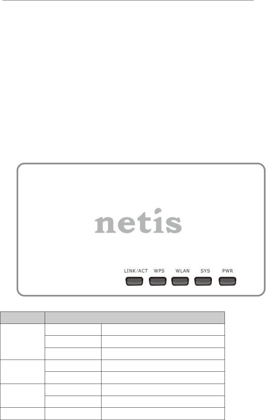
2.2. Panel Definition
Top view
Figure 2-1
LED
Function
LINK/ACT
On
Wired Connection normal
Flashing
Data transmitting
Off
Wired Connection abnormal
WPS
Flashing slowly
WPS is running
OFF
WPS is not running
WLAN
Flashing
Wireless data transmitting
Off
Wireless off
SYS
ON and Off
Abnormal
WF-2405 User Manual
9
Flashing
Normal
PWR
On
Power on
Off
Power off
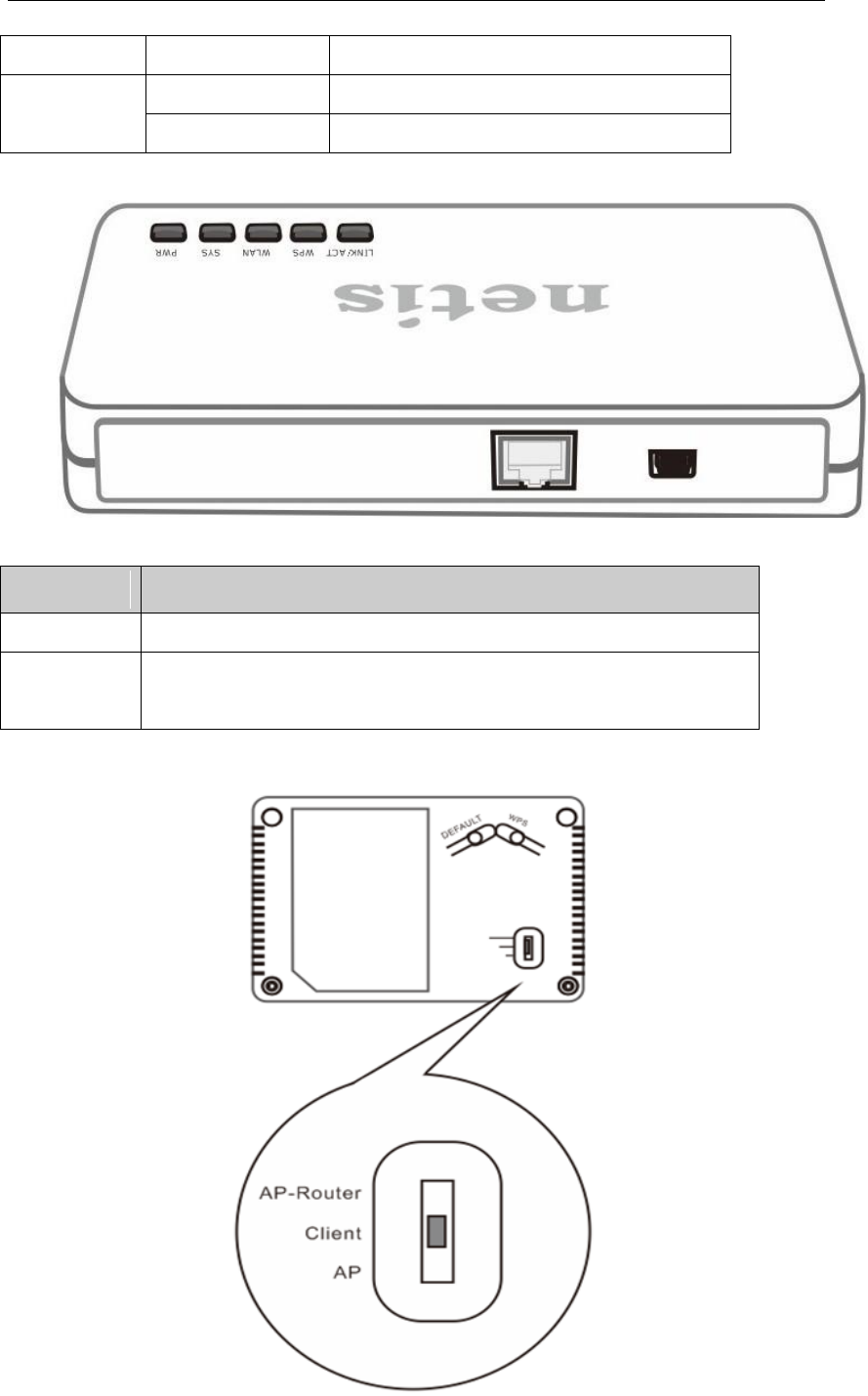
Side view
Figure 2-2
Description
Function
RJ45
Connect to ADSL/Cable modem or other network device
USB
Connect to Power adapter, please don‟t use the unknown power
adapter, otherwise your device may be damaged.
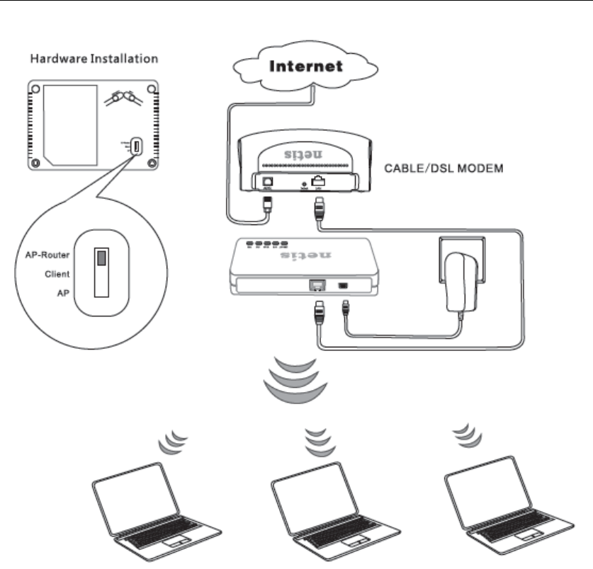
Bottom view

WF-2405 User Manual
10
Description
Function
DEFAULT
Restore factory configuration
WPS
Enable WPS setting
AP-Router
Switch to AP-Router mode
Client
Switch to Client mode
AP
Switch to AP mode
2.3. How to Restore factory configuration
If the router ever freezes in a setting change process or if you can‟t access it because you can‟t
remember the IP you have given it or other problem, you may have to utilize the reset button on
the back of the router to put it back to factory settings. You have to press and hole this button
for a few seconds (2-6s) with a pencil when it is working, then release and it will restore
settings to the factory configuration.
The other way to restore factory settings is through the same user interface used in setup.
Click on „System management‟- „Restore‟, and click on the „Restore‟ button.
2.4. Hardware Installation Procedures
The WF-2405 can work at AP-Router, Client, and AP mode. Each mode meets different
requirements, you can select corresponding mode as you wish. So please check which mode
is that you want, then install your device following the procedures below.
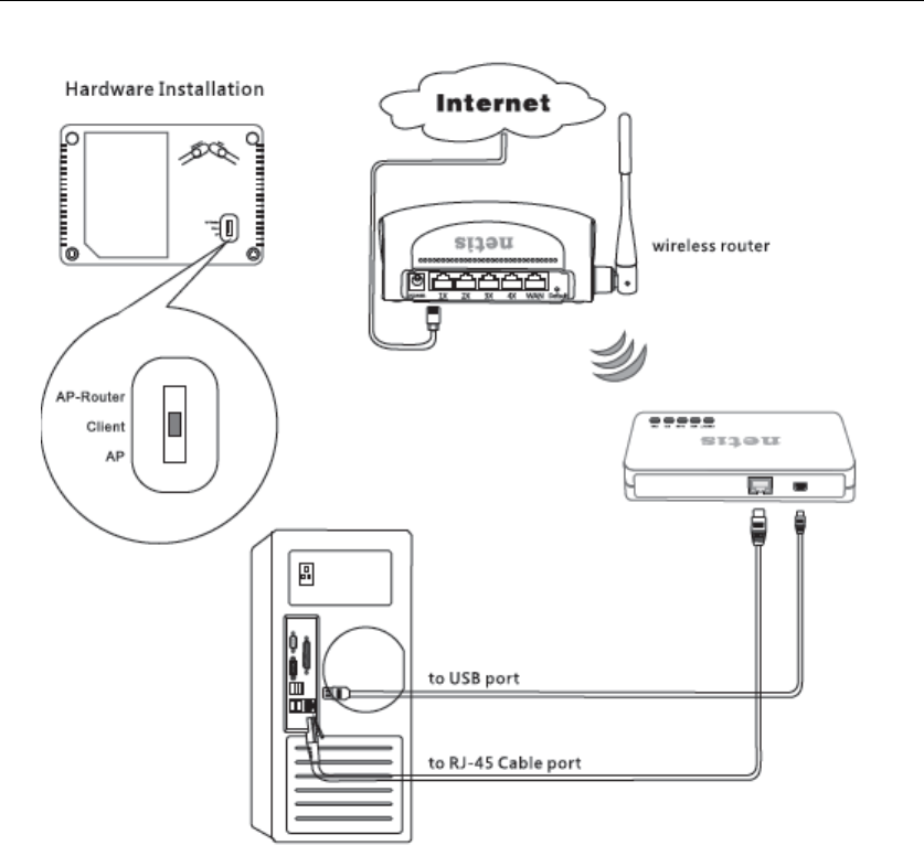
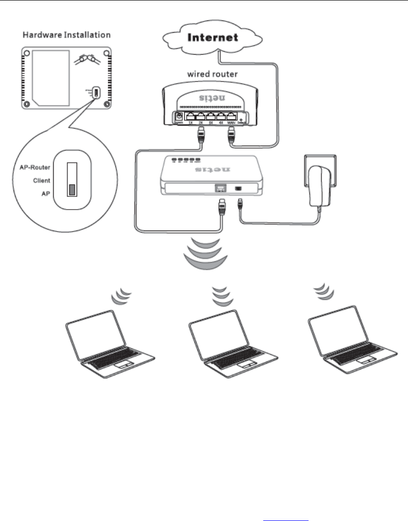
2.4.1. AP-Router mode
The device works as wireless router under this mode. Wireless clients(Notebook, tablet and
smart phone..) can connect to WF2405 via wireless, then access the internet. Select the
AP-Router mode and connect your device as figure 2-3.
WF-2405 User Manual
11
Figure 2-3
2.4.2. Client mode
The device work as a wireless card under this mode. Computer connect to RJ45 of WF-2405
via cable, then use WF-2405 to search and connect other AP or AP-Router. Please connect
your device as figure 2-4.
WF-2405 User Manual
12
Figure 2-4
2.4.3. AP mode
The device work as an access point under this mode. RJ45 of WF-2405 connect to other
broadband device(switch or router), then wireless client can connect to WF-2405 to access the
internet. Please connect your device as figure 2-5.
WF-2405 User Manual
13
Figure 2-5
3. How to configure AP-Router mode
3.1. Login web management page
Connect your device following the network topology in figure 2-3, then configure your
computer follow procedures below.
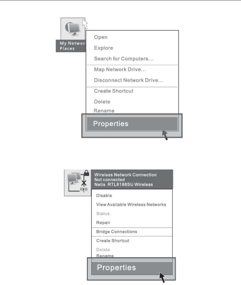
1) Select “My Network Places” on the desktop, right click, then choose “Properties”.
WF-2405 User Manual
14
Figure 3-1
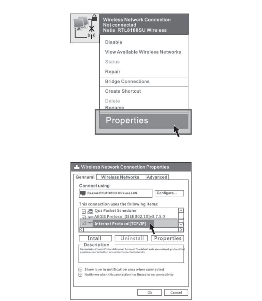
2) Select “Wireless Network connection”, right click, then choose “Properties”.
Figure 3-2
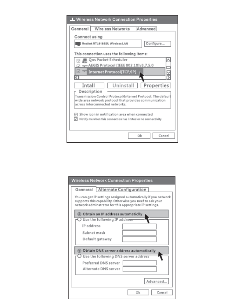
3) Select “Internet Protocol[TCP/IP]”, double click.
WF-2405 User Manual
15
Figure 3-3
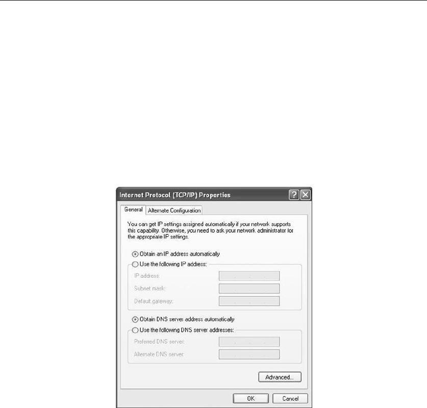
4) Choose “Obtain an IP address automatically” and “Obtain DNS server address
automatically”, then click “OK”.
Figure 3-4
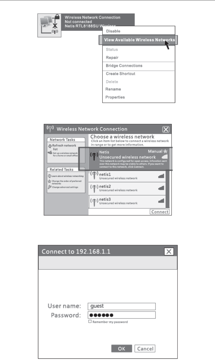
5) Return to network connection window, choose “Wireless Network connection”, right
click, then choose “View Available Wireless Networks”.
WF-2405 User Manual
16
Figure 3-5
6) Click “Refresh network list”, select SSID “netis” and double click.
Figure 3-6
7) Open the web browser, enter “192.168.1.1” in the address bar. Then enter the User name
“guest” and Password “guest” in the dialog box, click OK.
WF-2405 User Manual
17
Figure 3-7
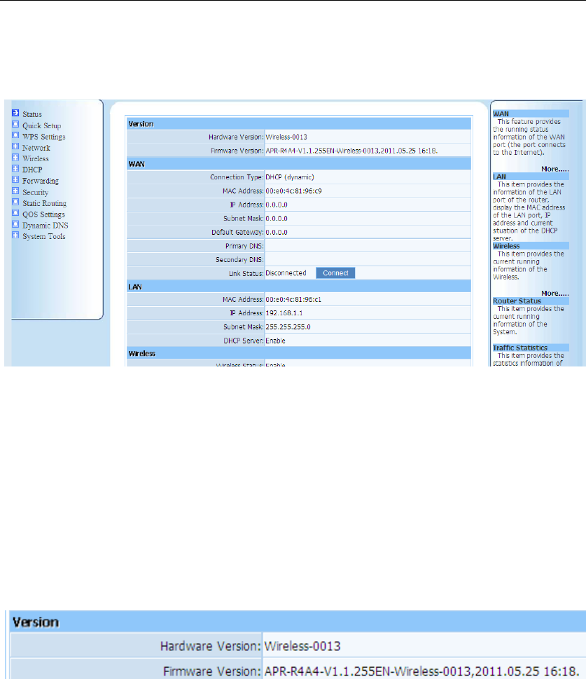
If you can see the picture as below(figure 3-8), that means you have successfully login web
management page of WF-2405. You can start configuring your WF-2405 now.
Figure 3-8
3.2. Status
This feature provides running status information and detailed information about router.
3.2.1. Version
Show the hardware version and firmware version.
Figure 3-9
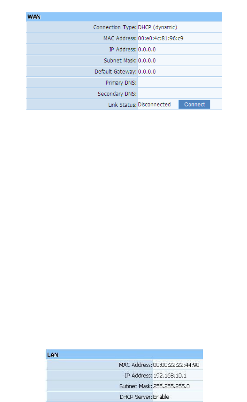
3.2.2. WAN
This feature provides running status information of the WAN port (the port connect to the
Internet)
WF-2405 User Manual
18
Figure 3-10
Connection Type: Display router‟s current connection type, It should be one of “PPPoE”,
“DHCP”, “Static IP”, depending on what kind of connection type your ISP provides.
Physical Address: The physical address of WAN port, this is a unique address assigned by
manufacturer.
IP Address: The IP address you obtained after connect to the Internet, if you haven‟t
connected to the Internet yet, this field is 0.0.0.0.
Subnet Mask: The Subnet mask you obtained after connect to the Internet, if you haven‟t
connected to Internet yet, this field is 0.0.0.0
Default Gateway: The IP address of Default gateway you obtained after connect to the
Internet, if you haven‟t connected to Internet yet, this field is 0.0.0.0.
Primary DNS: The DNS server translates domain or website names into IP address, input
the most common DNS server address you used or provided by your ISP.
Secondary DNS: Input IP address of a backup DNS server or you can leave this field blank
Link Status: Show the current status of link information. You can choose connect or
disconnect by manually.
3.2.3. LAN
This item provides information about router‟s LAN port, display LAN port‟s physical address,
IP address and current situation of DHCP server.
Figure 3-11
WF-2405 User Manual
19
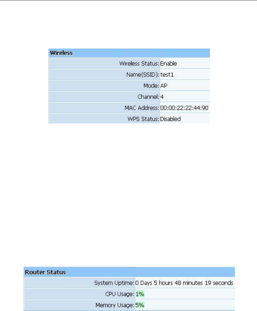
3.2.4. Wireless
This item provides current running information of wireless.
Figure 3-12
Wireless status: Display wireless interface status is enabled or not
Name (SSID): SSID (Service Set Identifier) is your wireless network's name shared
among all points in a wireless network.
Mode: Current wireless mode of wireless router
Channel: Display current channel of your wireless router.
MAC Address: The MAC address is used for wireless communication
WPS Status: Display WPS (Wi-Fi Protected Setup) status is enabled or not.
3.2.5. Router Status
This item provides current running information of System.
Figure 3-13
3.2.6. Traffic Statistics
This item provides statistics information about the bits router sends and received.
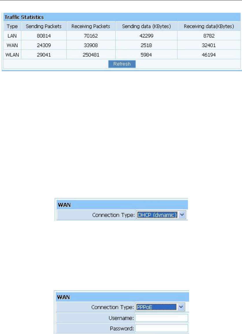
WF-2405 User Manual
20
Figure 3-14
3.3. Quick Setup
Providing you the convenient and simplest method for configure the router, the purpose of this
item is to provide an easy way for you to use it and configure your router to access the Internet
quickly; including „DHCP(dynamic)‟, „PPPoE‟, „Static‟ and „Wireless Configuration‟. This
is the most convenient tool for you to configure router.
3.3.1. DHCP (dynamic)
Figure 3-15
After select this item, you will obtain an IP address from your ISP automatically, those ISP who
supply Cable modem always use DHCP technology.
3.3.2. PPPoE
Figure 3-16
If your ISP provides you the PPPoE service (all ISP with DSL transaction will supply this
service, such as the most popular ADSL technique), please select this item. In the “Convenient
configuration” You can input your PPPoE username and password to access the Internet.
PPPoE Username: Input PPPoE username provided by ISP
PPPoE Password: Input PPPoE password provided by ISP.
WF-2405 User Manual
21
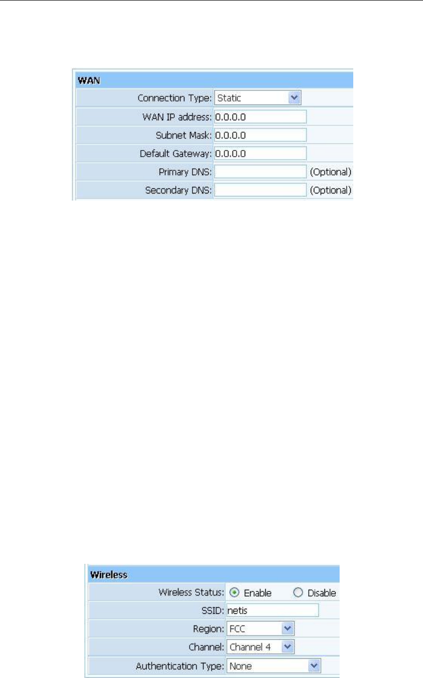
3.3.3. Static
Figure 3-17
This item should only be used when users use a static IP address to access Internet, you should
input your “WAN IP address”, ”subnet mask”,” default gateway” and “DNS server (domain
name server)” according to the information provided by your ISP. And every IP address should
be input in appropriate IP field, a IP address only divided into four IP octets by sign“.” is
acceptable.
WAN IP address: The IP address that your Internet access into
Subnet mask: Specify a Subnet Mask for your WAN segment
Default gateway: It is provided by your ISP
Primary DNS: DNS server is used for resolve domain name. Your ISP will provides you
with at least one DNS IP address, input IP address of your DNS server in this field
Secondary DNS: Input IP address of backup DNS server, or you can leave this field blank.
3.3.4. Wireless Configuration
You can choose “Enable” or “Disable” to enable or disable the wireless function. The default
setting is “enable”. If you chose the “Disable” status, the router will become a wired broadband
router without wireless function, so be careful when you choose this status.
Figure 3-18
SSID: SSID (Service Set Identifier) is your wireless network's name shared among all
WF-2405 User Manual
22
points in a wireless network. The SSID must be identical for all devices in the wireless
network. It is case-sensitive and must not exceed 32 characters. Make sure all points in the
wireless network have the same SSID. For added security, you should change the default
SSID to a unique name.
Region: Choose a correct region which fit your use environment.
Channel: Wireless router communicates to wireless cards in a particular channel, which
can reduce interference between different channels.
Authentication Type: Different authentication types use different encryption types, which
can encrypt wireless data to protect your wireless communication.
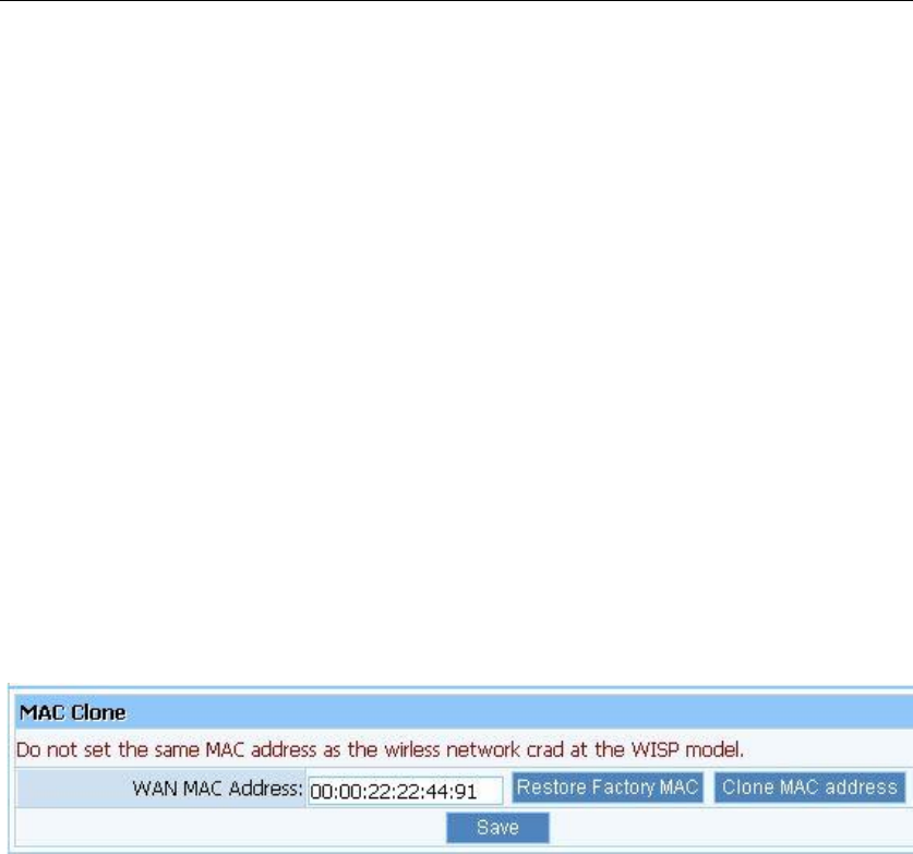
3.3.5. MAC Clone
The WAN port of router has a unique MAC address assigned by manufacturer; it called as
“Default MAC”. The “Clone MAC” is used for some special situations; For example, ISP only
allows certain MAC address to access the Internet, thus you can modify your WAN port‟s MAC
address in accord with the requirement of ISP, avoiding ISP‟s detection.
Figure 3-19
3.4. WPS Settings
Wi-Fi Protect Setup (WPS) function can let you create a safety network easily. You can through
„PIN Input Config (PIN)‟ or ‟Push Button (PBC)‟to encrypt your network. This router also
provides WPS button, you only need to push the WPS button in this router and the wireless
network card that support WPS function, then the router will be encrypted to WPA2-AES mode
automatically
Note:
If you have configured encryption mode in your router, then when you use this WPS function,
please configure the authentication type to none, and then it will be encrypted to WPA2-AES
mode automatically. If you don‟t want to change your authentication type, then when you use
this function, the router will be encrypted to the mode that you have configured.
WF-2405 User Manual
23
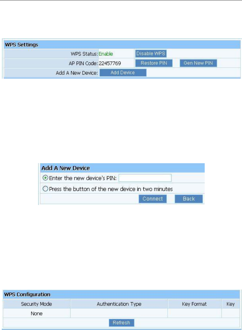
3.4.1. WPS Settings
Figure 3-20
WPS Status: You can use this function to setup the wireless connection between this router
and wireless network card. The default is Enable.
AP PIN Code: This code can mark a wireless product.
Add A New Device: Add a new device by WPS.
3.4.2. Add a New Device
Figure 3-21
Enter the new device‟s PIN: This code can mark a wireless product.
Press the button of the new device in two minutes: New device will send a PIN code to
wireless router.
3.4.3. WPS Configuration
Display the encryption information.
Figure 3-22
WPS can connect the wireless adapter and the router in a safe way. If you have a wireless
network card which has WPS button, you may set up a safe network via the following methods
Method 1:
1. Push the WPS button in the Router until the WPS LED is flashing several times
2. Push the WPS button in the wireless network card for about 3-5seconds
3. The safe connection will be established automatically
WF-2405 User Manual
24
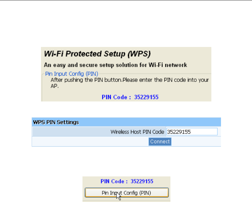
Method 2:
1. Input the PIN code of the adapter‟s WPS page into the router‟s WPS configure page, then
click ‟connect‟
Figure 3-23
Figure 3-24
2. Push the „PIN Input Config (PIN)‟ in the Wi-Fi protect setup of the adapter
Figure 3-25
3. Select this router in the pop-up window, then click „Select‟
4. The connection between the adapter and the router is be established automatically.
Method 3:
1. Select „Input PIN from AP‟ in WI-FI protect setup page, input PIN of the router, then click
„PIN Input Config (PIN)‟
2. Select this router in the pop-up window, then click „Select‟
3. The connection between the adapter and the router is be established automatically.
Remark
If there is more than one AP in the PBC mode when you use the method 1, there will be session
overlap. Please using method 2/3 or wait for a while push the button again.
3.5. Network
3.5.1. WAN
This item provides two access types for you to configure the WAN parameters. They are
wired access and wireless access.
WF-2405 User Manual
25
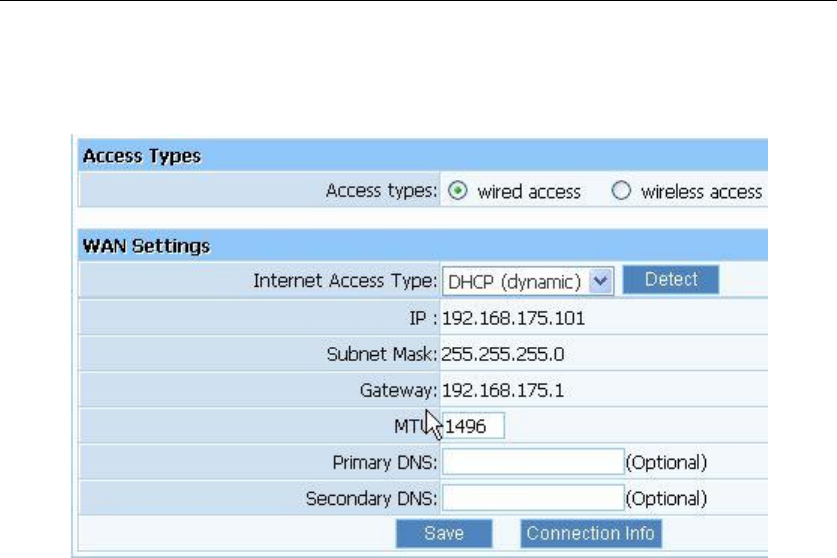
3.5.1.1. Wired Access
Figure 3-26
Internet Access Type: Ask for your ISP to get the correct access type.
IP: The IP address you obtained after connect to the Internet, if you haven‟t connected to
the Internet yet, this field is 0.0.0.0.
Subnet Mask: The Subnet mask you obtained after connect to the Internet, if you haven‟t
connected to Internet yet, this field is 0.0.0.0.
Gateway: The IP address of Default gateway you obtained after connect to the Internet, if
you haven‟t connected to Internet yet, this field is 0.0.0.0.
MTU: The MTU (Maximum Transmission Unit) setting specifies the largest packet size
permitted for network transmission. Most DSL users should use the value 1492.You can
set MTU manually, and you should leave this value in the 1200 to 1500 range. If the value
you set is not in accord with the value ISP provide, it may causes some problems, such as
fail to send Email, or fail to browse website. So if that happen, you can contact your ISP for
more information and correct your router‟s MTU value.
Primary DNS: The DNS server translates domain or website names into IP address, input
the most common DNS server address you used or provided by your ISP.
Secondary DNS: Input IP address of a backup DNS server or you can leave this field
blank.
WF-2405 User Manual
26
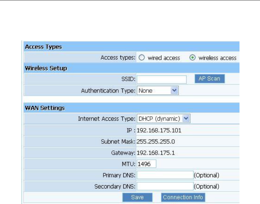
3.5.1.2. Wireless Access
Figure 3-27
SSID: SSID: SSID (Service Set Identifier) is your wireless network's name shared among
all points in a wireless network. The SSID must be identical for all devices in the wireless
network. It is case-sensitive and must not exceed 32 characters. Make sure all points in the
wireless network have the same SSID. For added security, you should change the default
SSID to a unique name.
Authentication Type: “None” means do not encrypt wireless data.
Internet Access Type: Ask for your ISP to get the correct access type.
IP: The IP address you obtained after connect to the Internet, if you haven‟t connected to
the Internet yet, this field is 0.0.0.0.
Subnet Mask: The Subnet mask you obtained after connect to the Internet, if you haven‟t
connected to Internet yet, this field is 0.0.0.0.
Gateway: The IP address of Default gateway you obtained after connect to the Internet, if
you haven‟t connected to Internet yet, this field is 0.0.0.0.
MTU: The MTU (Maximum Transmission Unit) setting specifies the largest packet size
permitted for network transmission. Most DSL users should use the value 1492.You can
set MTU manually, and you should leave this value in the 1200 to 1500 range. If the value
you set is not in accord with the value ISP provide, it may causes some problems, such as
fail to send Email, or fail to browse website. So if that happen, you can contact your ISP for
more information and correct your router‟s MTU value.
Primary DNS: The DNS server translates domain or website names into IP address, input
the most common DNS server address you used or provided by your ISP.
Secondary DNS: Input IP address of a backup DNS server or you can leave this field
blank.
WF-2405 User Manual
27
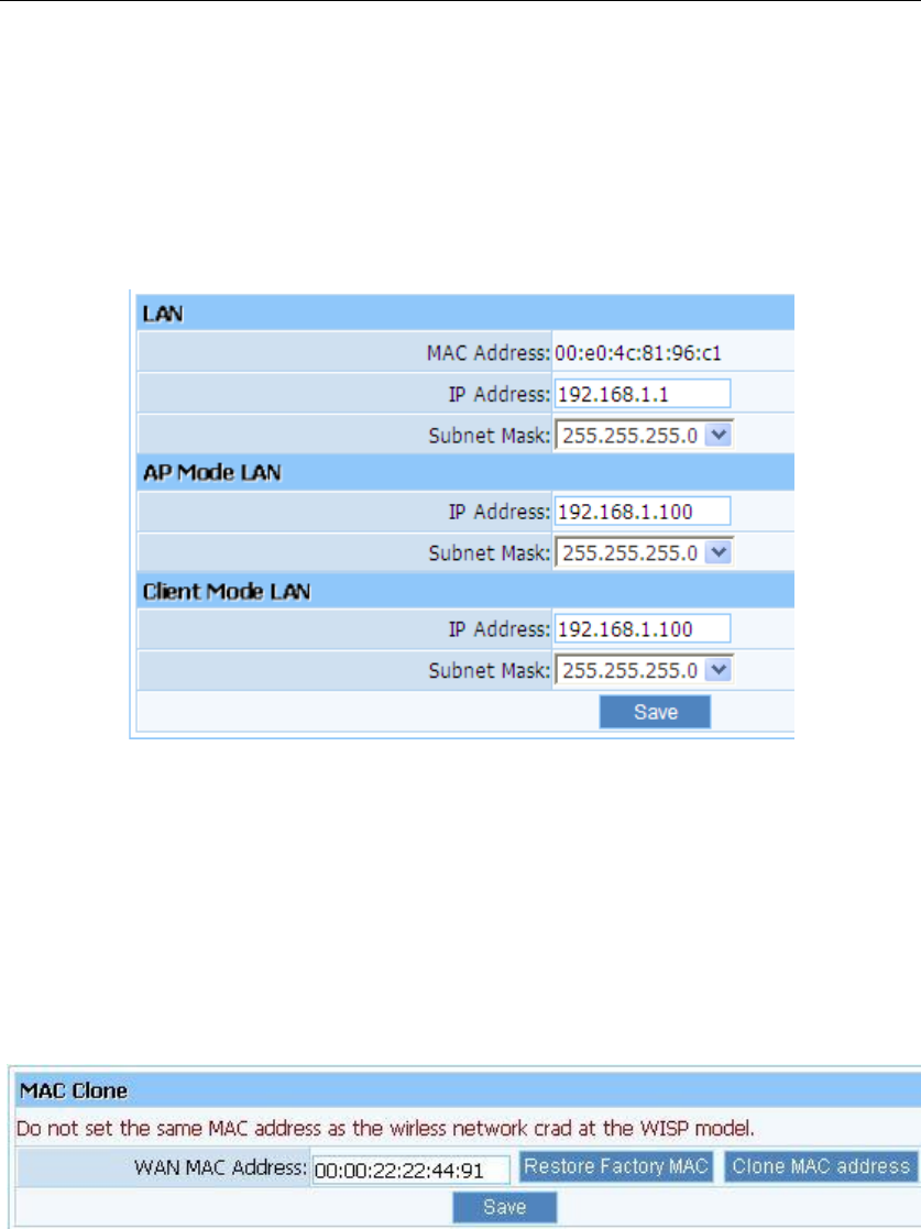
3.5.2. LAN
The IP address of LAN port is used for access router itself by computers that connect to the
router directly; here you can set IP address you need. The IP address format is like
***.***.***.***, and default IP address is 192.168.1.1, the default subnet mask is
255.255.255.0.
Figure 3-281
3.5.3. MAC Clone
The WAN port of router has a unique MAC address assigned by manufacturer; it called as
“Default MAC”. The “Clone MAC” is used for some special situations; For example, ISP only
allows certain MAC address to access the Internet, thus you can modify your WAN port‟s MAC
address in accord with the requirement of ISP, avoiding ISP‟s detection.
Figure 3-29
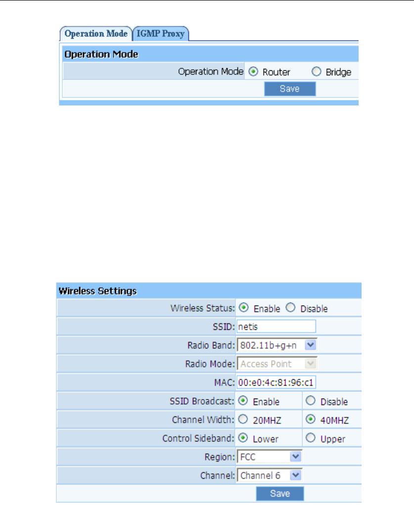
3.5.4. IGMP Proxy
Here you can set the IGMP Proxy „Router‟ and „Bridge‟.
WF-2405 User Manual
28
Figure 3-30
3.6. Wireless
3.6.1. Wireless Settings
Providing basic configuration items for wireless router users, including “wireless network
status”, “SSID”, “Radio Band”, “Radio Mode”, “MAC”, “SSID broadcasting”, “Channel
width”, “Channel sideband”, “Region” and “Channel” several basic configuration items.
Figure 3-31
Wireless network status: You can choose “enable” or “disable” to enable or disable the
“Wireless Network Status”, if what you choose is “Disable”, the AP function of wireless
router will be turned off.
SSID: The default is trst1.
Radio band: You can select the wireless standards running on your network, if you have
Wireless-N, and Wireless-B/G devices in your network, keep the default setting,
802.11b+g+n
Radio mode: Now WF-2405 only support Access Point.
MAC: Wireless router‟s physical address.
SSID Broadcasting: You can select “enable” or “disable” to enable or disable the broadcast
SSID function, If the setting of this field is disable, wireless client can‟t obtain this SSID to
WF-2405 User Manual
29
login in, then user have to input the SSID value manually.
Channel width: This switch allows you to set Router's wireless bandwidth. 20MHz: In this
mode you can get low bandwidth, little interference and slow rate. 40MHz: In this mode
you can get high bandwidth, high interference and rapid rate. Use only when you have a
pure router, draft 802.11n wireless network.
Channel sideband: It controls your wireless router use higher or lower channel when
working on 40MHz.
Region: please select the region where you live in.
Channel: In 20MHz, you can select one channel from 1 to 13 manually, and in 40MHz,
you can select one channel from 1 to 9 or 5 to 13, which provides a choice of avoiding
interference.
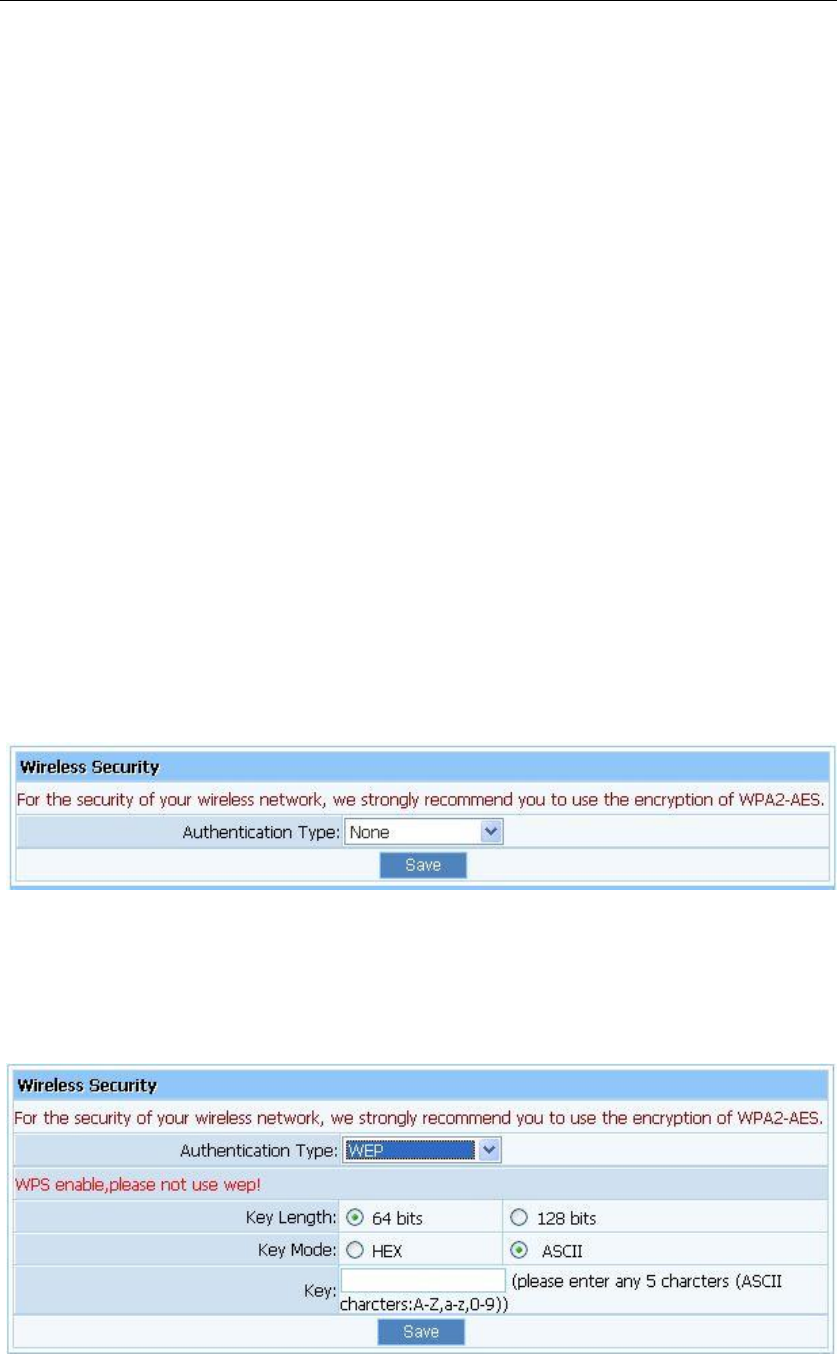
3.6.2. Wireless Security
The item allows you to encrypt your wireless communication, and you can also protect your
wireless network from unauthorized user access. It supplies “None”, “WEP”, “WPA-PSK”,
“WPA2-PSK” and “WPA/WPA2-PSK” five different encryption modes.
3.6.2.1. None
“None” means do not encrypt wireless data.
Figure 3-32
3.6.2.2. WEP
Figure 3-33
Key Length: There are two basic levels of WEP encryption, 64 bits and 128 bits, the
WF-2405 User Manual
30
more bits password have, the better security wireless network is, at the same time the
speed of wireless is more slower.
Key Mode: If you select WEP to encrypt your data, choose the bits of password, it should
be 64 bits or 128 bits. Then choose the format of password; it should be HEX or ASCII.
The valid character for HEX format should be numbers from 0 to 9 and letters from A to
F. HEX support mixed letter and number mode. And ASCII supports all characters that in
keyboard.
Key Length description: when you select 64bits, you need to input 10 chars for HEX and
5 chars for ASCII, and when you select 128bits, you need to input 26 chars for HEX and
13 chars for ASCII.
Note: when the WPS is enabled, please not use WEP.
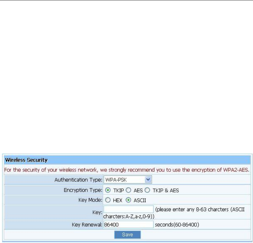
3.6.2.3. WPA-PSK
Figure 3-34
Encryption type: You can select the algorithm you want to use, TKIP, AES or
TKIP&AES. TKIP means “Temporal Key Integrity Protocol”, which incorporates
Message Integrity Code (MIC) to provide protection against hackers. AES, means
“Advanced Encryption System”, which utilizes a symmetric 128-Bit block data.
Key Renewal: you can configure the renewal time between 60 to 86400 seconds.
Key Length description: you need to input 8 to 63 ASCII characters no matter which type
you select.
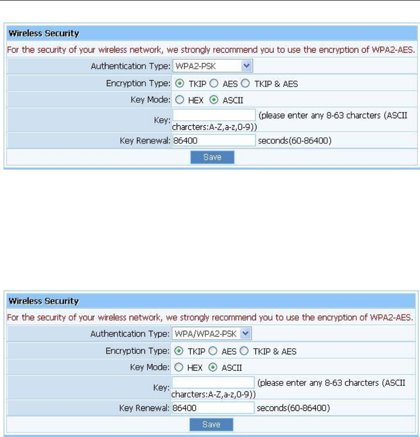
3.6.2.4. WPA2-PSK
The WPA2-PSK is similar to WPA-PSK and with stronger encryption method than WPA-PSK,
using WPA2-PSK; you should input password (leave this value in the range of 8 to 63
characters) and key renewal time (leave this value in the range of 60 to 86400 seconds).
WF-2405 User Manual
31
Figure 3-35
3.6.2.5. WPA/WPA2-PSK
This item mixed WPA-PSK and WPA2-PSK mode, which provides higher security level; you
can configure it according with WPA-PSK or WPA2-PSK.
Figure 3-36
WF-2405 User Manual
32
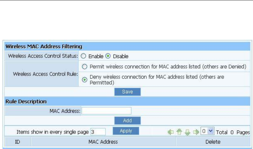
3.6.3. Wireless MAC Filtering
Figure 3-37
MAC Filter Status: the default is disable. You can filter wired users by enabling this
function; thus unauthorized users can not access the network.
Description: describe MAC Filter list to tell from different MAC Filter lists.
Rule: you can select permit or deny. The default is permit.
MAC address: input the MAC address that you want to control. The default format is
**-**-**-**-**-**(e.g.: 00-22-33-da-cc-bb).
Follow the following steps to set MAC filter:
1. Enable MAC Filter, then select save.
2. Add MAC address you want to control in the “MAC address” field (the format is
**-**-**-**-**-**), then click “Add” button, and you will see the MAC address has displayed
in the MAC list.
3. There are two items supplied, “Permit wireless connection for MAC address listed (others
are Denied)” and “Deny wireless connection for MAC address listed (others are Permitted)”,
Select the item you want, and click “Save” button.
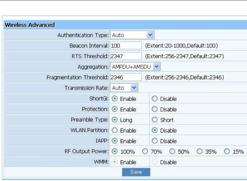
3.6.4. Wireless Advanced
These settings are only for more technically advanced users who have a sufficient knowledge
about wireless LAN. These settings should not be changed unless you know what effect the
change will have on your AP.
WF-2405 User Manual
33
Figure 3-38
Authentications type: The default is set to “Auto”, which allows “Open System” or
“Shared Key” authentication to be used. Select “Shared Key” if you only want to use
“Shared Key” authentication (the sender and recipient use a WEP key for authentication).
Beacon Interval: The interval time of this 150Mbps Wireless-N Broadband Router
broadcast a beacon. Beacon is used to synchronize the wireless network. The valid interval
is 20-1000, the default is 100.
RTS Threshold: You can set RTS Threshold value in this field, the valid range should be
256-2347 and default value is 2347. If a network packet is smaller than the preset RTS
threshold size, the RTS/CTS mechanism will not be enabled.
Aggregation: You can accelerate the wireless transmission speed by enabling the
aggregation function. The default is AMPDU+AMSDU.
Fragmentation Threshold: It specifies the maximum size of packet during the
fragmentation of data to be transmitted.
Transmission Rate: Transmit rate indicates the transmission speed of wireless LAN
access .The default setting is “Auto” and you can set this value between 1-54Mbps range.
ShortGi: You can select “Enable” or “disable” for shortgi.
Protection: Using 802.11b and 802.11g mixed mode may result in poor network
performance. By enabling 802.11 protection, it will ameliorate performance of 802.11g
devices in your wireless network.
WF-2405 User Manual
34
Preamble Type: "Short Preamble" is suitable for heavy traffic wireless network. "Long
Preamble" provides much communication reliability; the default setting is "Long
Preamble”.
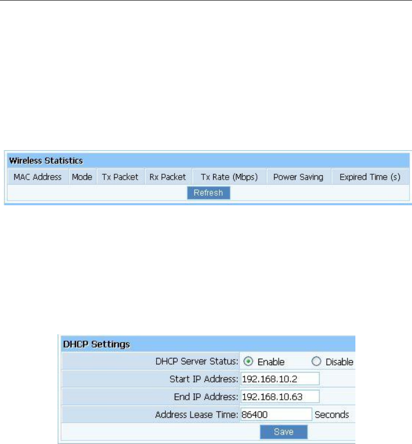
3.6.5. Wireless Statistics
Display current status of the wireless client associate with AP.
Figure 3-39
3.7. DHCP
3.7.1. DHCP Settings
Figure 3-40
DHCP Server Status: Keep the default setting “Enable”, so router is able to use DHCP
function. If a DHCP server has already existed in the network, please select “Disable”.
Start IP Address: The IP Address is used for allocate IP address by DHCP server; enter the
start IP address.
End IP Address: The IP Address is used for allocate IP address by DHCP server; enter the
end IP address.
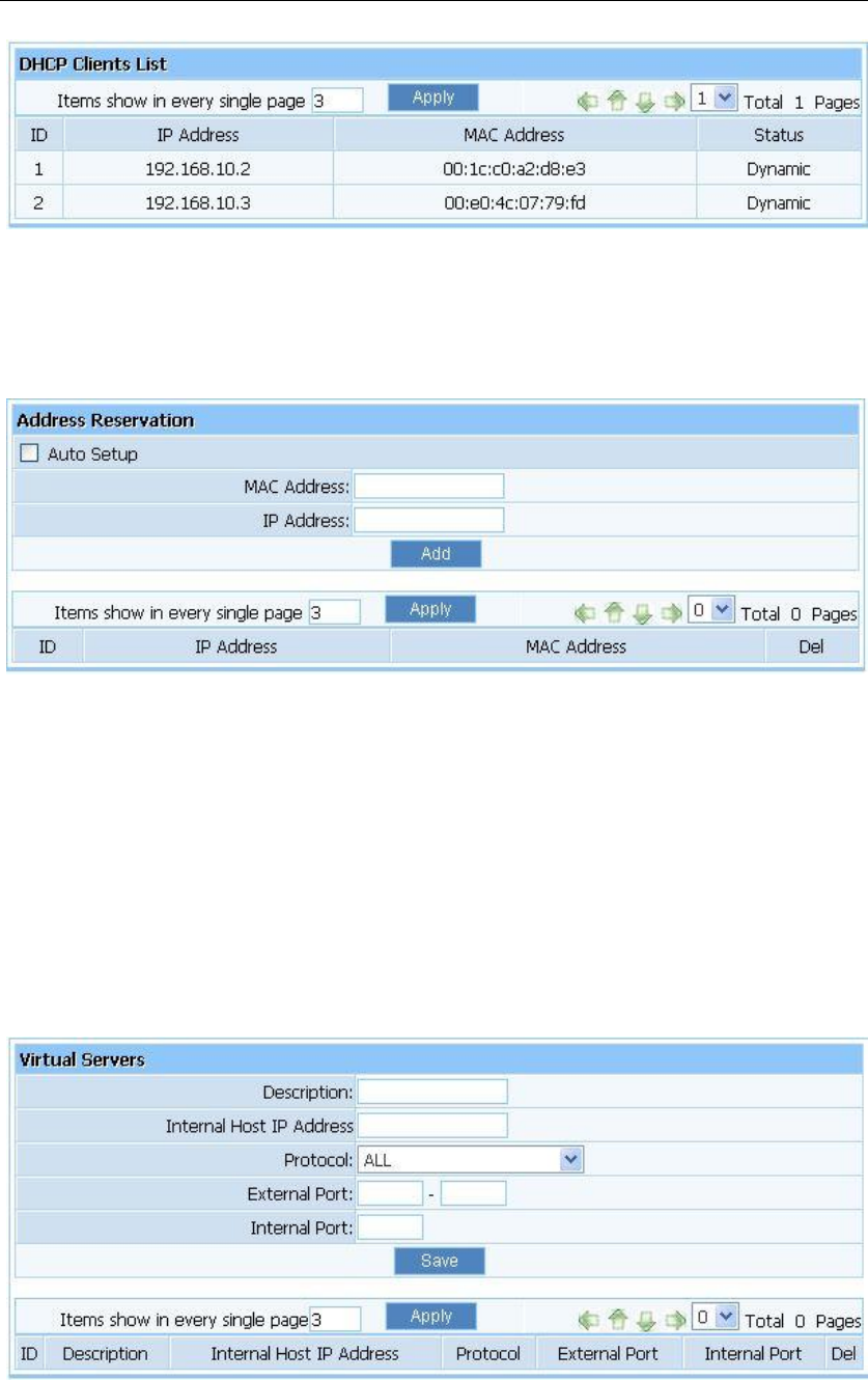
3.7.2. DHCP Clients List
Display the state of assigned IP by DHCP Server.
WF-2405 User Manual
35
Figure 3-41
3.7.3. Address Reservation
Figure 3-42
Address Reservation: reserve IP address for designed physical address host. If you want
to configure a fixed IP address for some host, please input physical address and IP
address, then click add.
3.8. Forwarding
3.8.1. Virtual Servers
Figure 3-43
Description: Describe current virtual server item.
WF-2405 User Manual
36
Internal Host IP Address: The “Internal Host IP Address” indicates IP address of the
internal host using virtual server.
Protocol: The protocol item supplies several protocols. For example, if you have web
server within LAN, you can select the HTTP template then the router will input port
number 80 automatically.
External Port: Input an extranet port number (the users in Internet can see these ports).
Internal Port: Input an intranet port number.
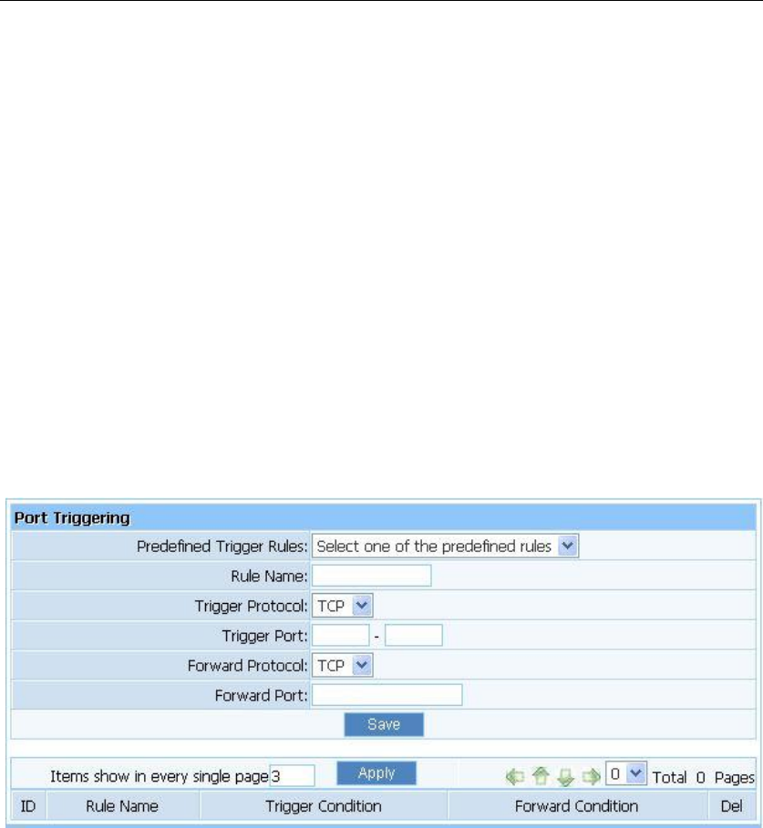
3.8.2. Port Triggering
Port trigger module dynamically registers virtual server rules when any IP host generates the
packet from the specified trigger protocol and port. Port trigger module use forward protocol
type and port number and use the IP address of host that generates the trigger packet when it
registers a rule.
Figure 3-44
Predefined Trigger Rules: select one of the Predefined Rules.
Rule Name: describe one Predefined Trigger that you will configure.
Trigger Protocol: you can select TCP/UDP.
Trigger Port: you can select a part of ports.
Forward Protocol: you can select TCP/UDP.
Forward Port: you can select a part of ports.
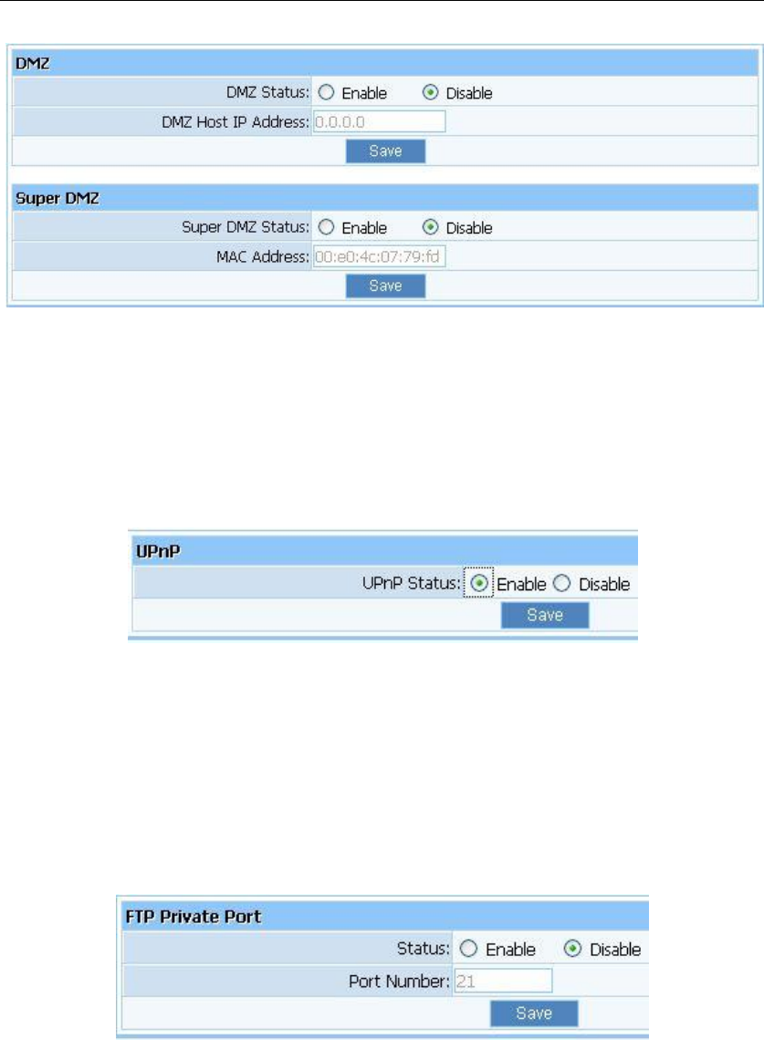
3.8.3. DMZ
DMZ opens all the ports of one computer, exposing the computer to the Internet. So it should
only be used for some special-purpose, especial for Internet online games. Using this function
you can select “DMZ” item and input IP address of DMZ host, then click “Save”. For the
purpose of security, we suggested that using “Virtual servicer” instead of “DMZ”.
WF-2405 User Manual
37
Figure 3-45
3.8.4. UPnP
The UPnP function supports load Application‟s port forward record automatically. Select
“Enable” to enable this function.
Figure 3-46
3.8.5. FTP Private Port
Some games, servers, and applications (such as BT, QQ video, Edunkey, Web server) are no
longer effect when behind the NAT router, so this item provides function of port mapping from
LAN to WAN.
Figure 3-47
3.9. Security
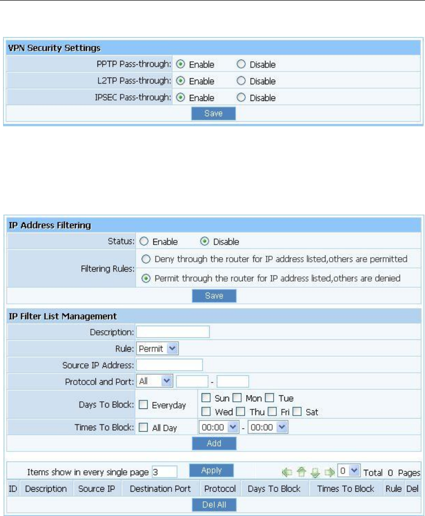
3.9.1. Security Settings
VPN is commonly used for encapsulate and encrypt data across the public network. For VPN
WF-2405 User Manual
38
tunnel, the router supports IPSEC pass-through, PPTP pass-through and L2TP pass-through.
Figure 3-48
3.9.2. IP Address Filtering
Figure 3-49
Status: the default is disable. The rules of “Internet access control” based on source IP,
port number and protocol.
Description: describe IP Firewall list to tell from different IP Firewall lists.
Rule: you can select permit or deny. The default is permit.
Source IP address: input the source IP address that you want to control. The default
format is ***.***.***.***(e.g: 192.168.2.3).
Protocol and Port: If the rule has already existed in “Protocol Template”. You can select
appropriate item and apply it. Or you can input protocol type and port number manually,
click “add” button, then the item will displayed in the list.
WF-2405 User Manual
39
Follow the following steps to set Internet Access Control:
1. You can select “enable” and click “Save” to enable “IP Firewall” function. This is only the
first step, you should continued to create appropriate rules for “IP Firewall”.
2. Input description information for current access control rule in the “Description” field. Input
IP address of host you want to restrict.
3. There are two items supplied, “Permit through the router for IP address listed, others are
denied” and “Deny through the router for IP address listed, others are permitted”, Select the
item you want, and click “Save” button.
4. If you want to delete certain item on the list, select appropriate item on the list, click “delete”
to delete it.
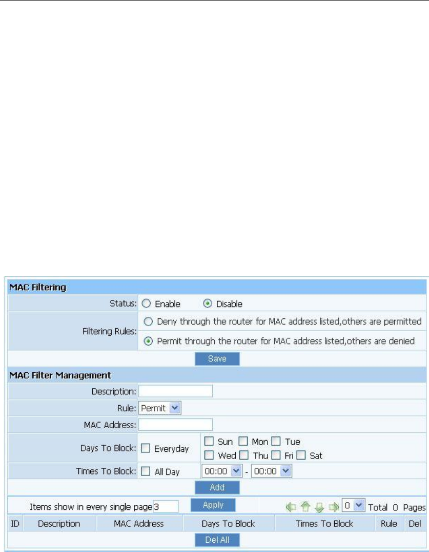
3.9.3. MAC Filtering
Figure 3-50
Status: the default is disable. You can filter wired users by enabling this function; thus
unauthorized users can not access the network.
Description: describe MAC Filter list to tell from different MAC Filter lists
Rule: you can select permit or deny. The default is permit
MAC address: input the MAC address that you want to control. The default format is
**-**-**-**-**-**(e.g.: 00-22-33-da-cc-bb)
Follow the following steps to set MAC filter:
1. Enable MAC Filter, then select save.
WF-2405 User Manual
40
2. Add MAC address you want to control in the “MAC address” field (the format is
**-**-**-**-**-**), then click “Add” button, and you will see the MAC address has displayed
in the MAC list.
3. There are two items supplied, “Permit wireless connection for MAC address listed (others
are Denied)” and “Deny wireless connection for MAC address listed (others are Permitted)”,
Select the item you want, and click “Save” button.
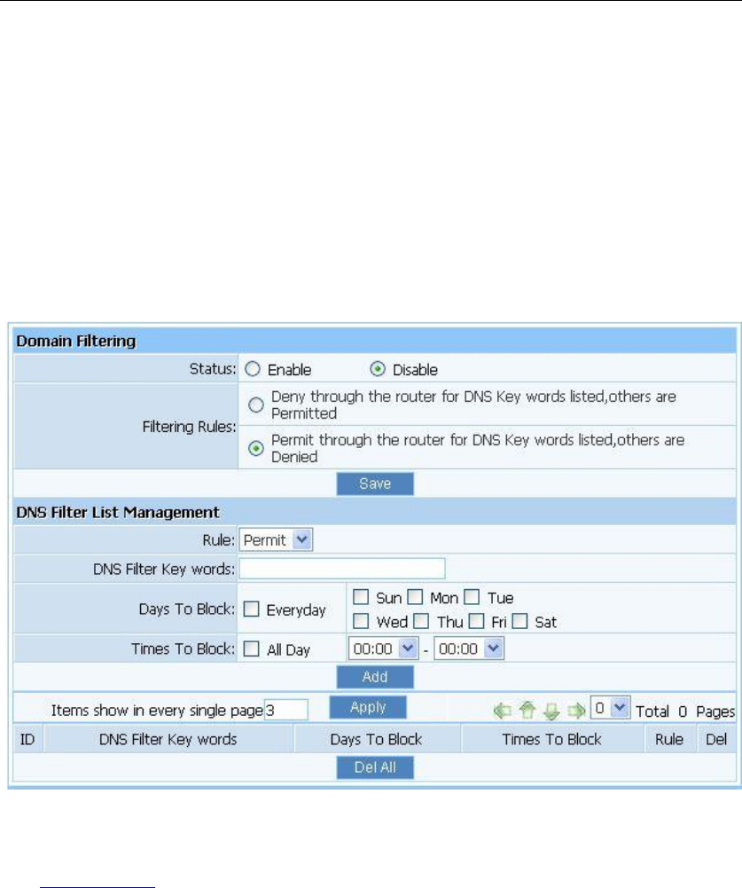
3.9.4. Domain Filtering
Figure 3-51
Status: the default is disable. “DNS filter” is able to filter certain domain name such as
www.sina.com.
Rule: you can select permit or deny. The default is permit.
DNS Filter Key words: Input website name or Domain name in the “DNS Key Words”
field, such as www.163.com.
Follow these steps to set DNS filter:
1. You can select “enable” and click “Save” to enable “DNS Filter” function. This is only the
first step, you should continued to create appropriate rules for “DNS Filter”.
2. Input DNS Filter Key words.
3. There are two items supplied, “Permit through the router for DNS Key words listed, others
are denied” and “Deny through the router for DNS Key words listed, others are permitted”,
Select the item you want, and click “Save” button.
4. If you want to delete certain item on the list, select appropriate item on the list, click “delete”
WF-2405 User Manual
41
to delete it.
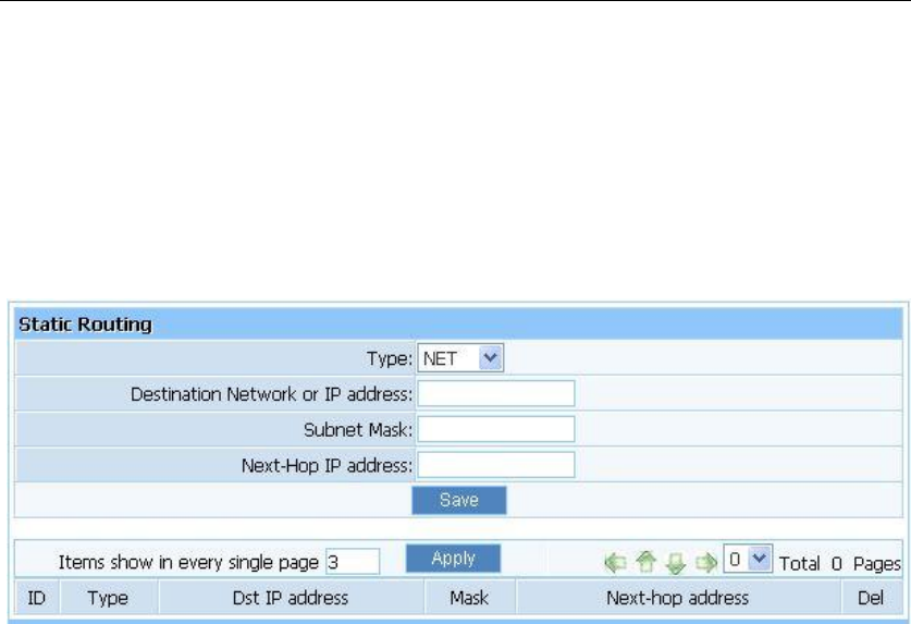
3.10. Static Routing
Most of broadband router and wireless router are using NAT mode, so this feature is designed
for most common network environment.
Figure 3-52
Destination Network or IP Address: Specify a certain destination Network or IP address
which static route forward to.
Subnet Mask: Subnet mask is used for distinguish Network portion and Host portion for an
IP address.
Next-hop IP Address: This is an IP address of the next-hop device (and also is the gateway
address for local host) that allows forwarding data between router and remote network or
host.
Routing Table: You can check out all current route items, click “delete” button to delete an
route item existed in routing table.
WF-2405 User Manual
42
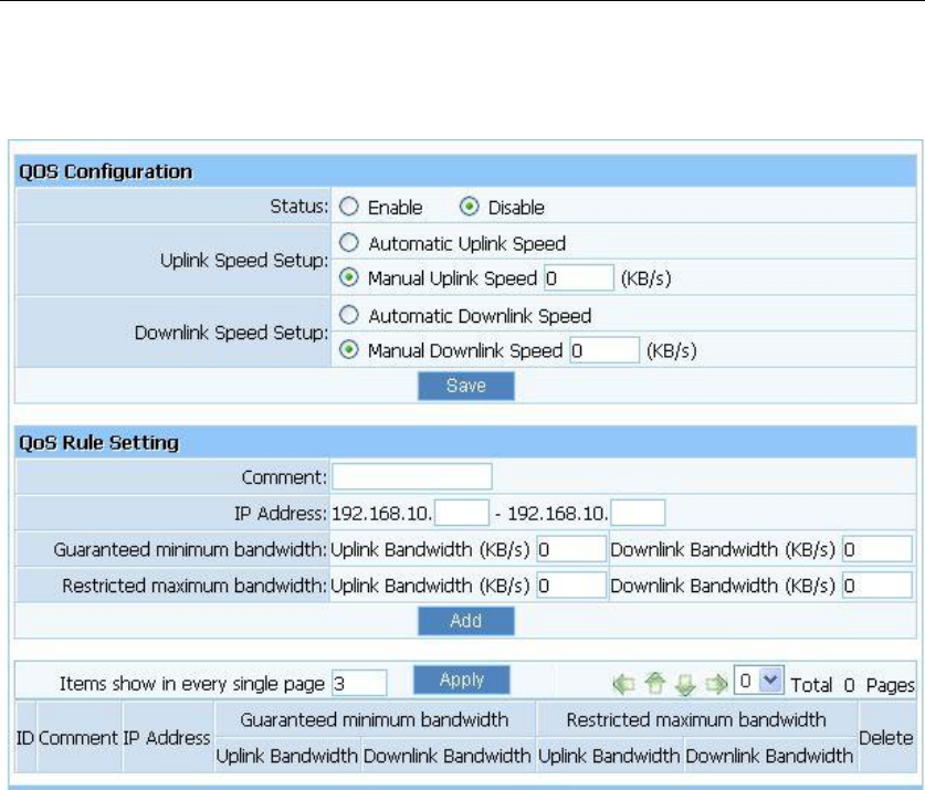
3.11. QOS Settings
Figure 3-53
Status: QOS switch.
Automatic Uplink Speed: Router adjusts uplink bandwidth automatically.
Manual Uplink Speed (Kbps): User configures uplink bandwidth manually.
IP Address: Set the IP address range for restricted hosts.
Minimum bandwidth: setup uplink and downlink bandwidth.
Maximum bandwidth: setup uplink and downlink bandwidth.
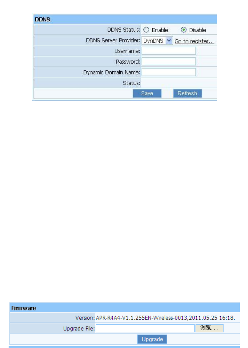
3.12. Dynamic DNS
The DDNS feature allows you using domain name (not IP address) to access Internet. Before
you can use this feature, you need to register an account for DDNS service at DDNS service
providers, such as “roay.cn”, ”TZO.com”, ”DynDNS”. For more information, you can visit
http://www.oray.net/Help.
WF-2405 User Manual
43
Figure 3-54
DDNS Status: Current status of DDNS server.
DDNS Server Provider: For example, if you want to use service of “roay.cn”, you have to
first register and accounts for it. Other DDNS service providers as the same.
Username, Password, Dynamic Domain Name: After register an DDNS account from
DDNS service providers, you will get “User Name”, “Password”, ”Dynamic Domain
Name”, Input information in appropriate field.
3.13. System Tools
System management includes password setup, web Setup, upgrade, reboot, restore, WOL and
System time
3.13.1. Firmware
Click "Browse..."button and select a File to upgrade, after you have selected the appropriate file,
click "Upgrade" button to execute upgrade procedure. Do not cut off the power supply during
the process of upgrading.
Figure 3-55
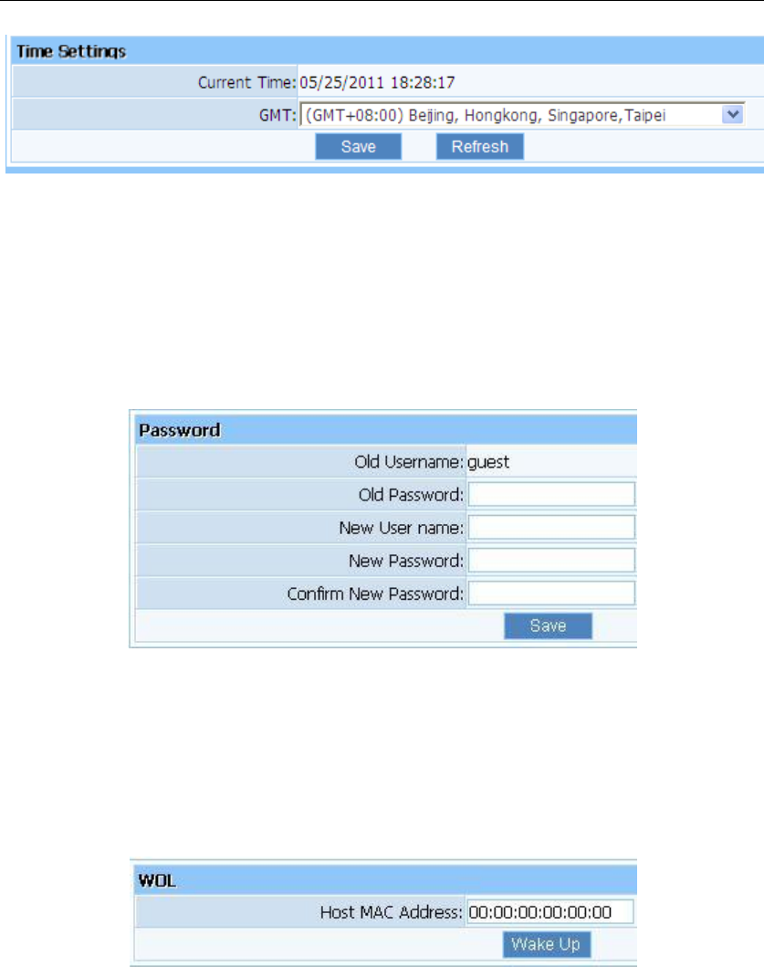
3.13.2. Time Settings
You can choose the time server and the time zone for the system time.
WF-2405 User Manual
44
Figure 3-56
3.13.3. Password
The default username/password is guest/guest. To ensure the Router‟s security, it is suggested
that you change the default password to one of your choice, here enter a new password and then
Re-enter it again to confirm your new password. Click “Save” button to save settings.
Figure 3-57
3.13.4. WOL
Input host MAC address, and then click button of "Wake up" to wake up the target host which in
the LAN.
Figure 3-58
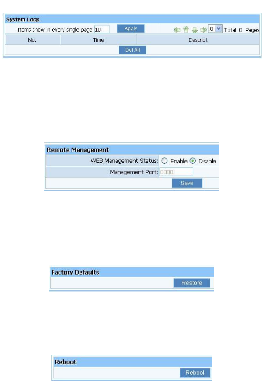
3.13.5. System Logs
Examine system logs. You can configure items shown in one Page, the default is 10.
WF-2405 User Manual
45
Figure 3-59
3.13.6. Remote Management
WEB Management Status: the default is disable. Router can be accessed on the remote site
using “Web setup”. Check the “Management Port” and enter the port number and then press
“save” button to enable web management.
Figure 3-60
3.13.7. Factory Defaults
Click "Restore" button, the Router will erase all of your settings and replace them with the
factory defaults, make sure you have backup current settings before click this button.
Figure 3-61
3.13.8. Reboot
Click “Reboot” button to restart the router.
Figure 3-62
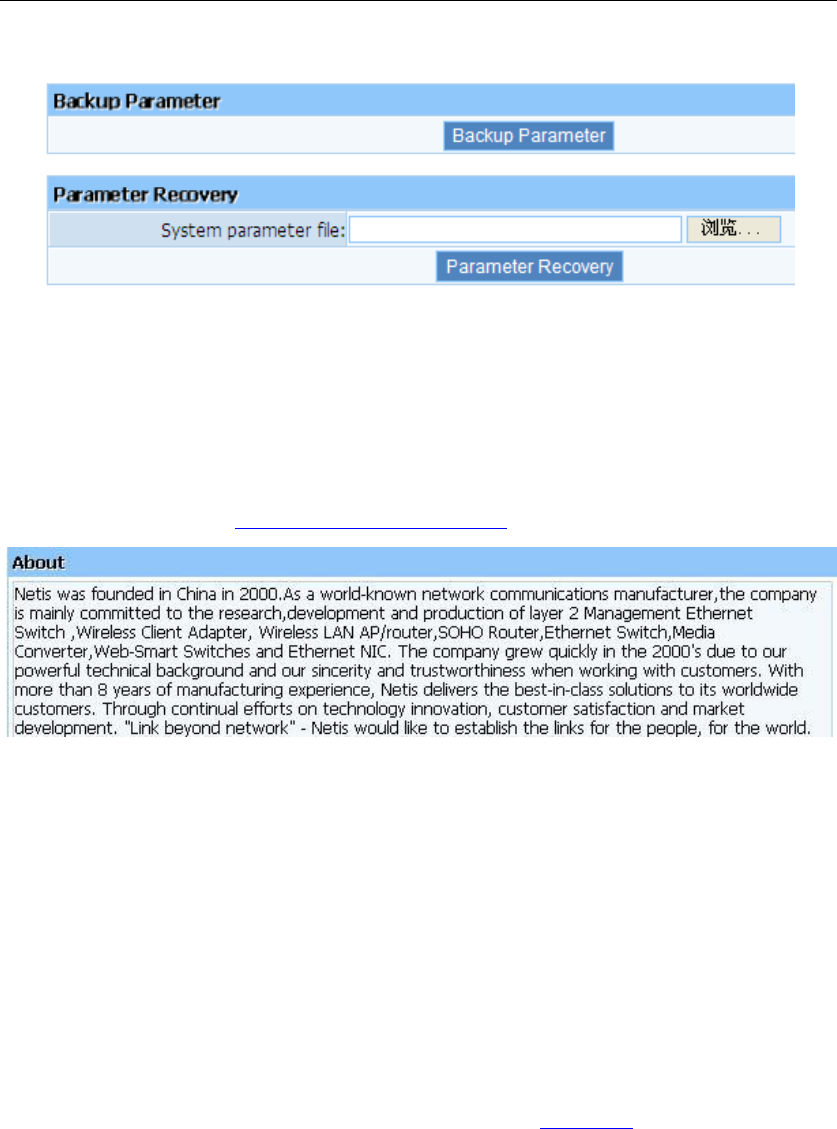
3.13.9. Backup
Click “Backup Parameter ” button to backup system parameter as a file. you can recovery
WF-2405 User Manual
46
system parameter setting from a old parameter file.
Figure 3-63
3.14. About
This item shows company information of netis. If you want more information about netis,
please access this website http://www.netis-systems.com/
Figure 3-64
4. How to configure Client mode
4.1. Login web management page
Note: The DHCP server is disable under client mode, so you need to configure a static IP
address for WF-2405, then you can login the web page of the device.
Connect your device following the network topology in figure 2-4, then configure your
computer follow procedures below.
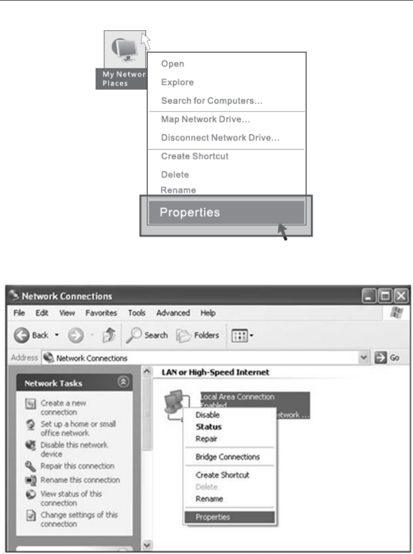
1) Select “My Network Places” on the desktop, right click, then choose “Properties”.
WF-2405 User Manual
47
Figure 4-1
2) Select “Local Area connection”, right click, then choose “Properties”.
Figure 4-2
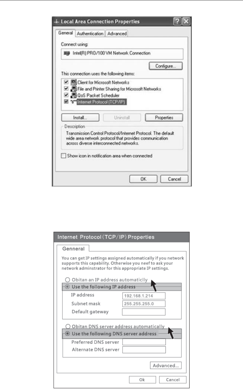
3) Select “Internet Protocol[TCP/IP]”, double click.
WF-2405 User Manual
48
Figure 4-3
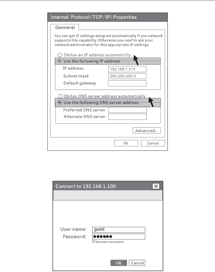
4) Select “Use the following IP address” and input IP address “192.168.1.214”, input
Subnet mask “255.255.255.0”, then choose “Obtain DNS server address
automatically”, then click “OK”.
Figure 4-4
5) Open the web browser, enter “192.168.1.100” in the address bar. Then enter the User
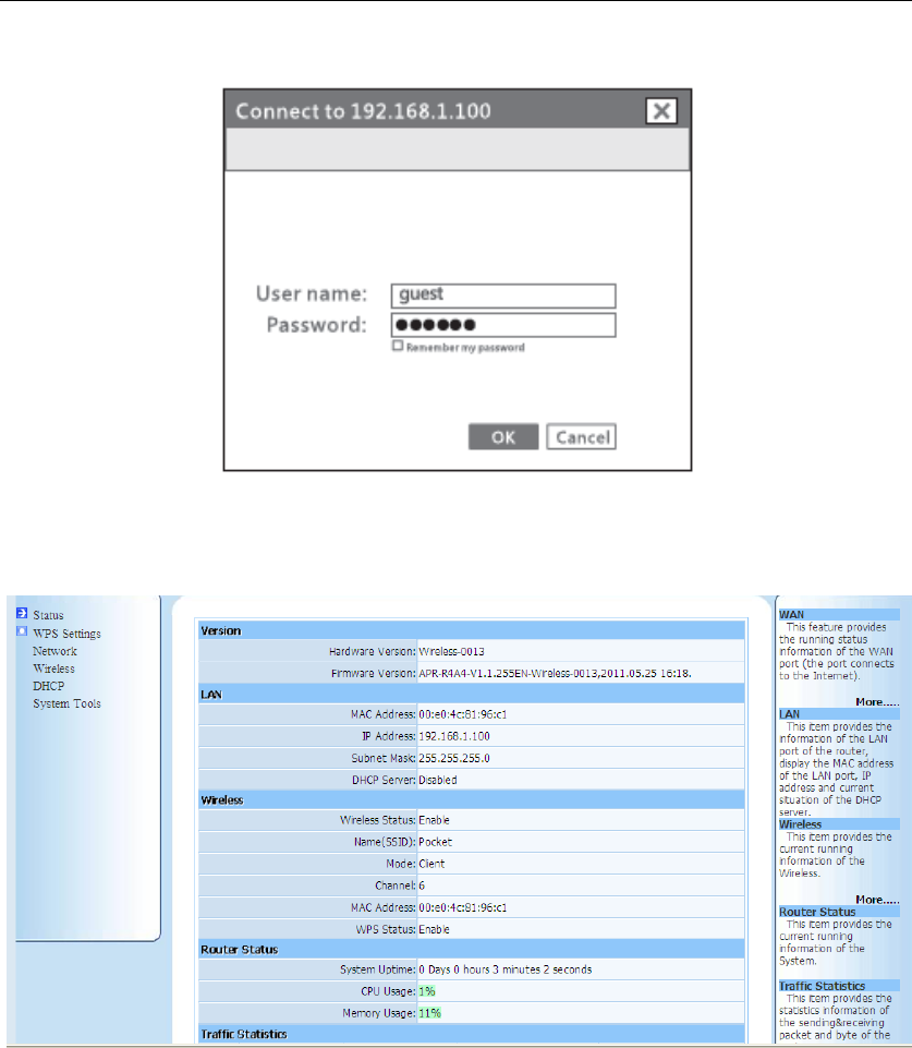
WF-2405 User Manual
49
name “guest” and Password “guest” in the dialog box, click OK.
Figure 4-5
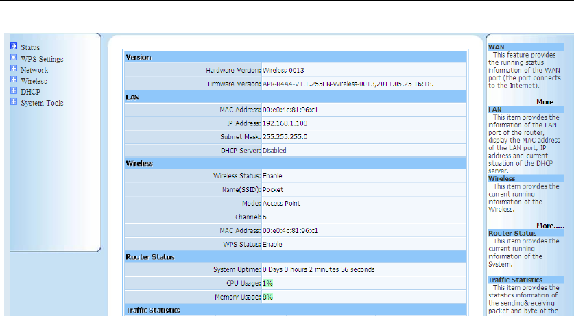
If you can see the picture as below(figure 4-6), that means you have successfully login web
management page of WF-2405. You can start configuring your WF-2405 now.
Figure 4-6
As you can see, when the device works under client mode, there are 7 items in the web page.
These items have already been described in AP-Router mode, so you can refer to
corresponding item in chapter 3. Please pay attention on chapter 4.2, which will show you
how to connect internet under client mode.
4.2. How to connect internet under client mode
1) Click “Wireless” to open wireless setting page, then click “AP Scan”.
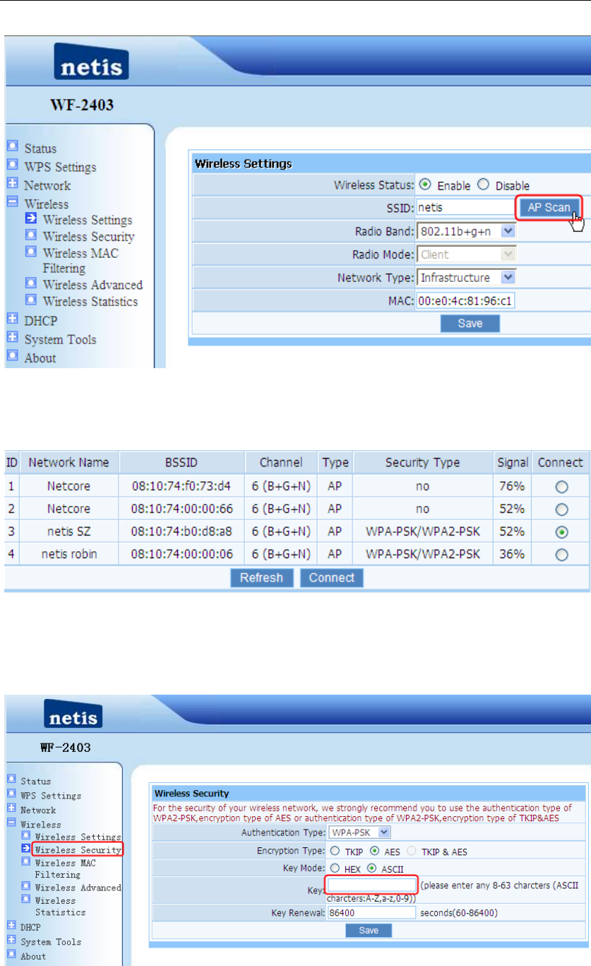
WF-2405 User Manual
50
Figure 4-7
2) You can see several SSID of the AP or AP-Router like figure 4-10, select the SSID that
you want to connect, click “Connect” button. Here we use “netis SZ” for example.
Figure 4-8
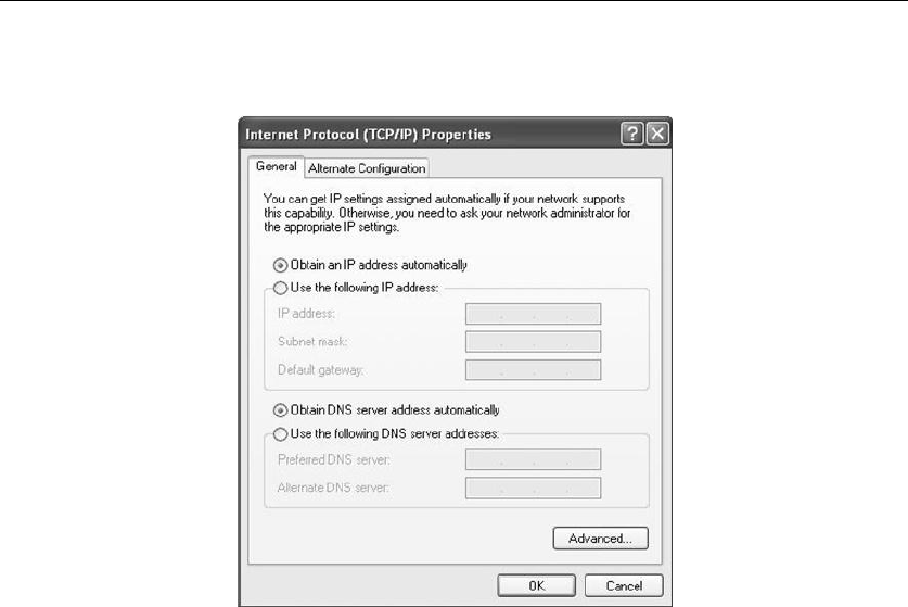
3) If AP has been encrypted, you need configure the wireless security for WF-2405. When
configuring wireless security, please make sure authentication type and the key is same
as AP‟s setting.
Figure 4-9
WF-2405 User Manual
51
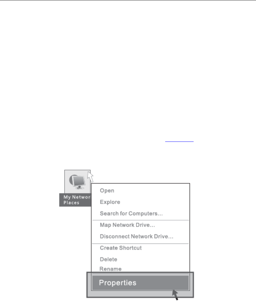
4) After finishing configure WF-2405, please return to your computer to change the IP
address. You can use static IP or obtain an IP automatically.
Figure 4-10
4.3. Status
Please refer to chapter 3.2 .
4.4. WPS Settings
Please refer to chapter 3.4 .
4.5. Network
Please refer to chapter 3.5 .
4.6. DHCP
Note: When the device works under client mode, it acts like a wireless adapter, don‟t need to
change this option. Keep its status disable, so your computer could get IP address from other
broadband device.
4.7. System Tools
Please refer to chapter 3.13 .
WF-2405 User Manual
52
4.8. About
Please refer to chapter 3.14 .
5. How to configure AP mode
5.1. Login web management page
Note: The DHCP server is disable under AP mode, so you need to configure a static IP
address for WF-2405, then you can login the web page of the device.
Connect your device following the network topology in figure 2-5, then configure your
computer follow procedures below.
1) Select “My Network Places” on the desktop, right click, then choose “Properties”.
Figure 5-1
2) Select “Wireless Network Connection”, right click, then choose “Properties”.
WF-2405 User Manual
53
Figure 5-2
3) Select “Internet Protocol[TCP/IP]”, double click.
Figure 5-3
4) Select “Use the following IP address” and input IP address “192.168.1.214”, input
Subnet mask “255.255.255.0”, then choose “Obtain DNS server address
automatically”, then click “OK”.
WF-2405 User Manual
54
Figure 5-4
5) Open the web browser, enter “192.168.1.100” in the address bar. Then enter the User
name “guest” and Password “guest” in the dialog box, click OK.
Figure 5-5
If you can see the picture as below(figure 5-6), that means you have successfully login web
management page of WF-2405. You can start configuring your WF-2405 now.
WF-2405 User Manual
55
Figure 5-6
As you can see, when the device works under client mode, there are 7 items in the web page.
These items have already been described in AP-Router mode, so you can refer to
corresponding item in chapter 3.
5.2. Status
Please refer to chapter 3.2 .
5.3. WPS Settings
Please refer to chapter 3.4 .
5.4. Network
Please refer to chapter 3.5 .
5.5. Wireless
Please refer to chapter 3.6 .
5.6. DHCP
Note: When the device works under AP mode, don‟t need to change this option. Keep its
status disable, so your computer could get IP address from other broadband device.
WF-2405 User Manual
56
5.7. System Tools
Please refer to chapter 3.13 .
5.8. About
Please refer to chapter 3.14 .
Note: After finishing configure WF-2405, please return to your computer to change the IP
address. You can use static IP or obtain an IP automatically.
Figure 5-7
6. Troubleshooting
6.1. I cannot access the Web-based Configuration Utility from the Ethernet
computer used to configure the router.
Check that the LAN LED is on. If the LED is not on, verify that the cable for the LAN
connection is firmly connected.
Check whether the computer resides on the same subnet with the router‟s LAN IP address.
If the computer acts as a DHCP client, check whether the computer has been assigned an
IP address from the DHCP server. If not, you will need to renew the IP address.
Use the ping command to ping the router‟s LAN IP address to verify the connection.
Make sure your browser is not configured to use a proxy server.
Check that the IP address you entered is correct. If the router‟s LAN IP address has been
changed, you should enter the reassigned IP address instead.

WF-2405 User Manual
57
6.2. I forget Password (Reset the Router without Login)
Use a pencil to press the button for about 2-6 seconds when it is working, then leave your
hands, it will restore settings to the factory configuration. The default password is guest.
6.3. I have some problems related to Connection with Cable Modem
Please follow the following steps to check the problems:
Check whether the DSL modem works well or the signal is stable. Normally there will be
some indicator lights on the modem, users can check whether the signal is ok or the
modem works well from those lights. If not, please contact the ISP.
Check the front panel of the Router, there are also some indicator lights there. When the
physical connection is correct, the Power light and the CPU light should be solid; the
WAN light should be blinking. If you use your computer, the corresponding LAN port
light should be blinking too. If not, please check whether the cables work or not.
Repeat the steps in WAN Setup Connect with Internet through DSL Modem.
6.4. I can browse the router’s Web-based Configuration Utility but cannot access
the Internet.
Check if the WAN LED is ON. If not, verify that the physical connection between the
router and the DSL/Cable modem is firmly connected. Also ensure the DSL/Cable modem
is working properly.
If WAN LED is ON, open the System Overview page of the Web configuration utility and
check the status group to see if the router‟ s WAN port has successfully obtained an IP
address.
Make sure you are using the correction method (Dynamic IP Address, PPPoE, or Static IP)
as required by the ISP. Also ensure you have entered the correct settings provided by the
ISP.
For cable users, if your ISP requires a registered Ethernet card MAC address, make sure
you have cloned the network adapter‟ s MAC address to the WAN port of the router. (See
the MAC Address field in WAN Setup.)
6.5. My wireless client cannot communicate with another Ethernet computer.
Ensure the wireless adapter functions properly. You may open the Device Manager in
Windows to see if the adapter is properly installed.
Make sure the wireless client uses the same SSID and security settings (if enabled) as the

WF-2405 User Manual
58
150Mbps Wireless-N Broadband Router.
Ensure that the wireless adapter‟s TCP/IP settings are correct as required by your network
administrator.
If you are using a 802.11b wireless adapter, and check that the 802.11G Mode item in
Wireless Basic Setting page, is not configured to use 802.11G Performance.
Use the ping command to verify that the wireless client is able to communicate with the
router‟s LAN port and with the remote computer. If the wireless client can successfully
ping the router‟ s LAN port but fails to ping the remote computer, then verify the TCP/IP
settings of the remote computer.