NEXCOM NIO51 Mesh Wi-Fi Device Gateway User Manual
NEXCOM international Co.,LTD Mesh Wi-Fi Device Gateway Users Manual
UserManual.wiki
>
NEXCOM
>
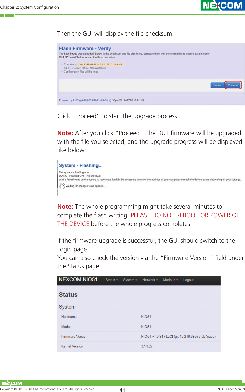
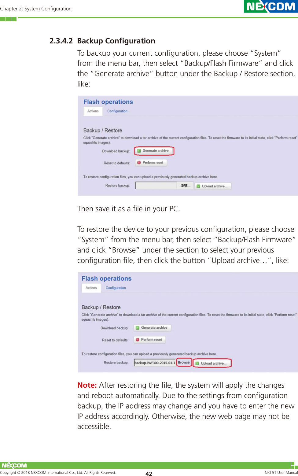
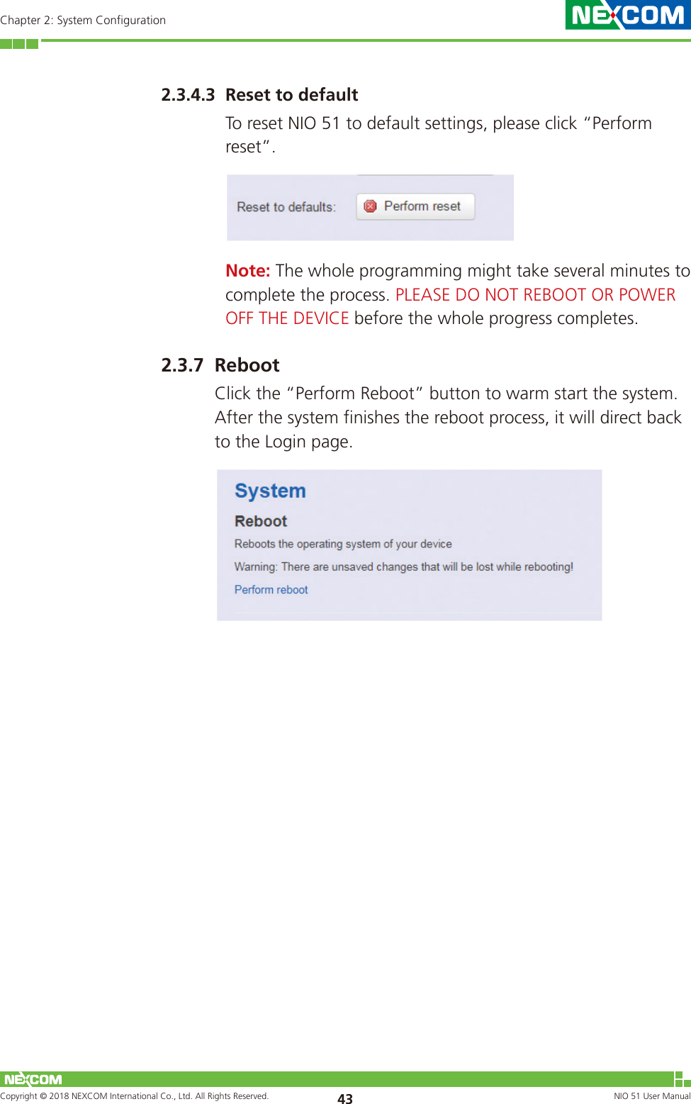
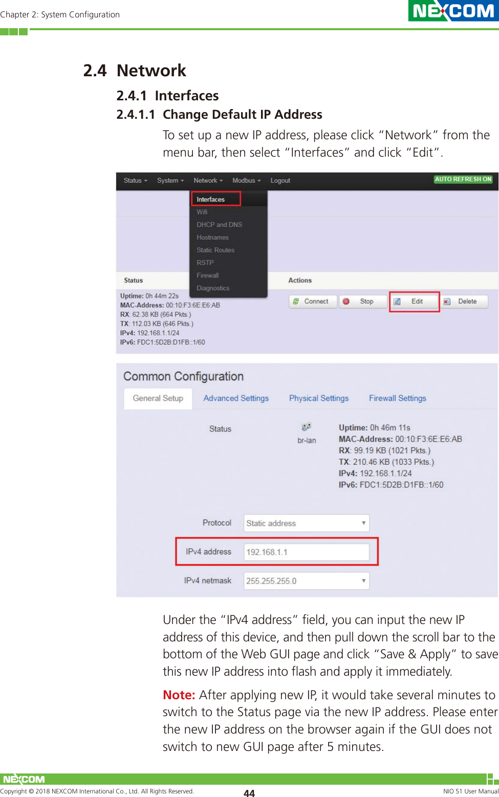
NIO51 User Manual
Users Manual
Navigation menu
Upload a User Manual
Namespaces
Wiki Guide
HTML
PDF
Info
Views
User Manual
Discussion / Help
Navigation

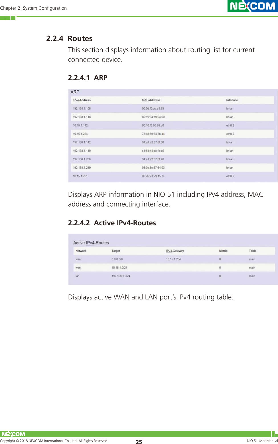
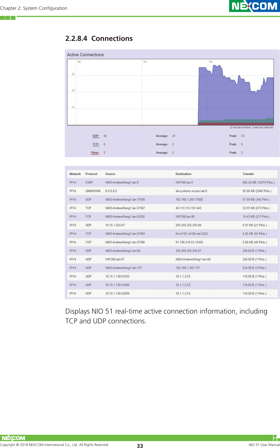
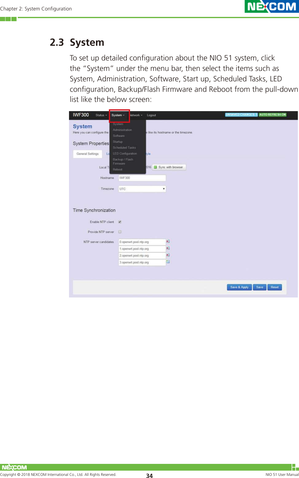
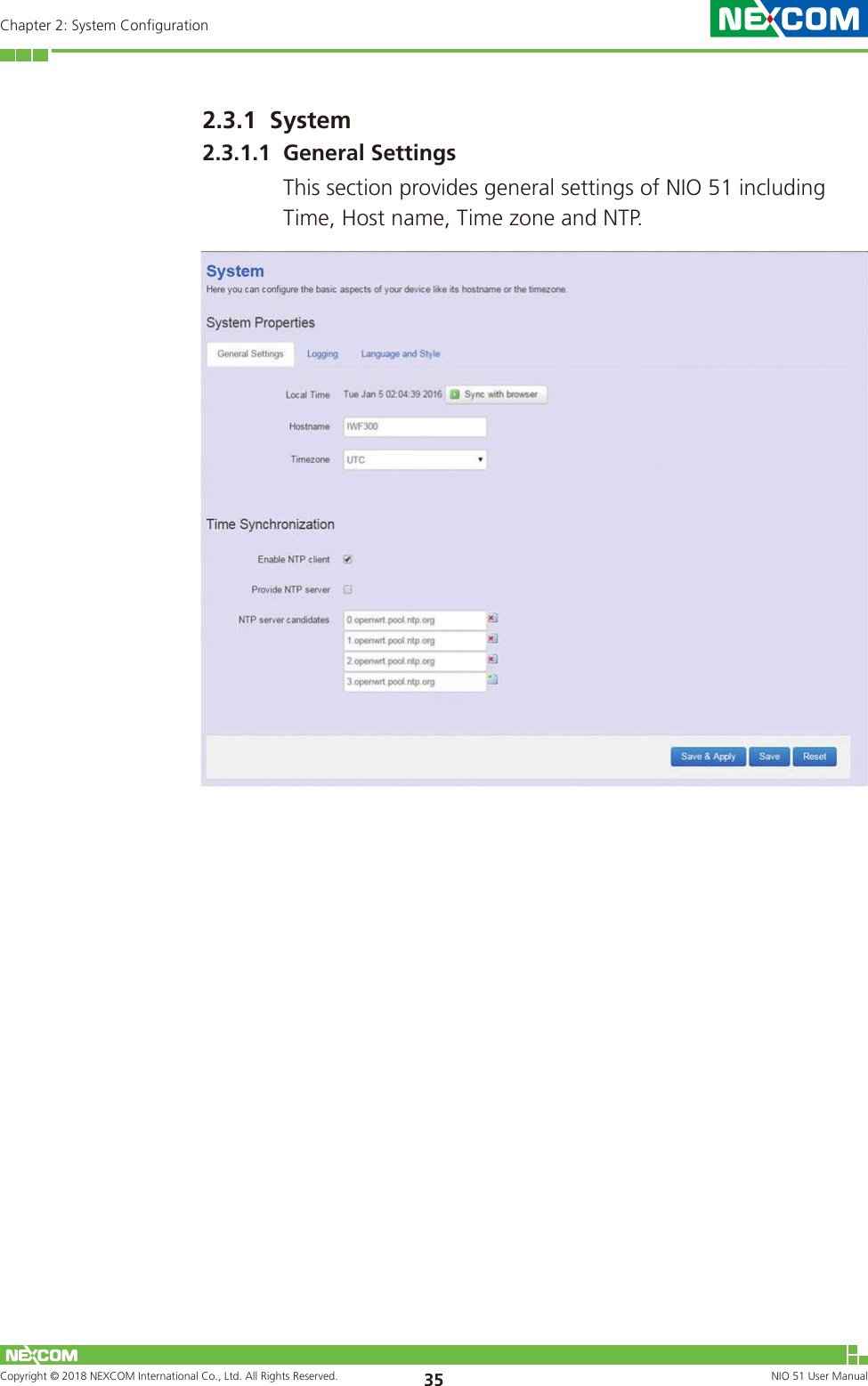
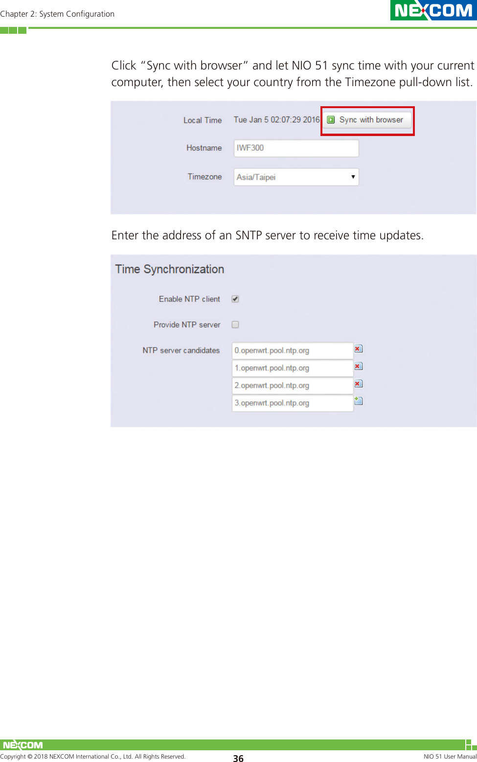
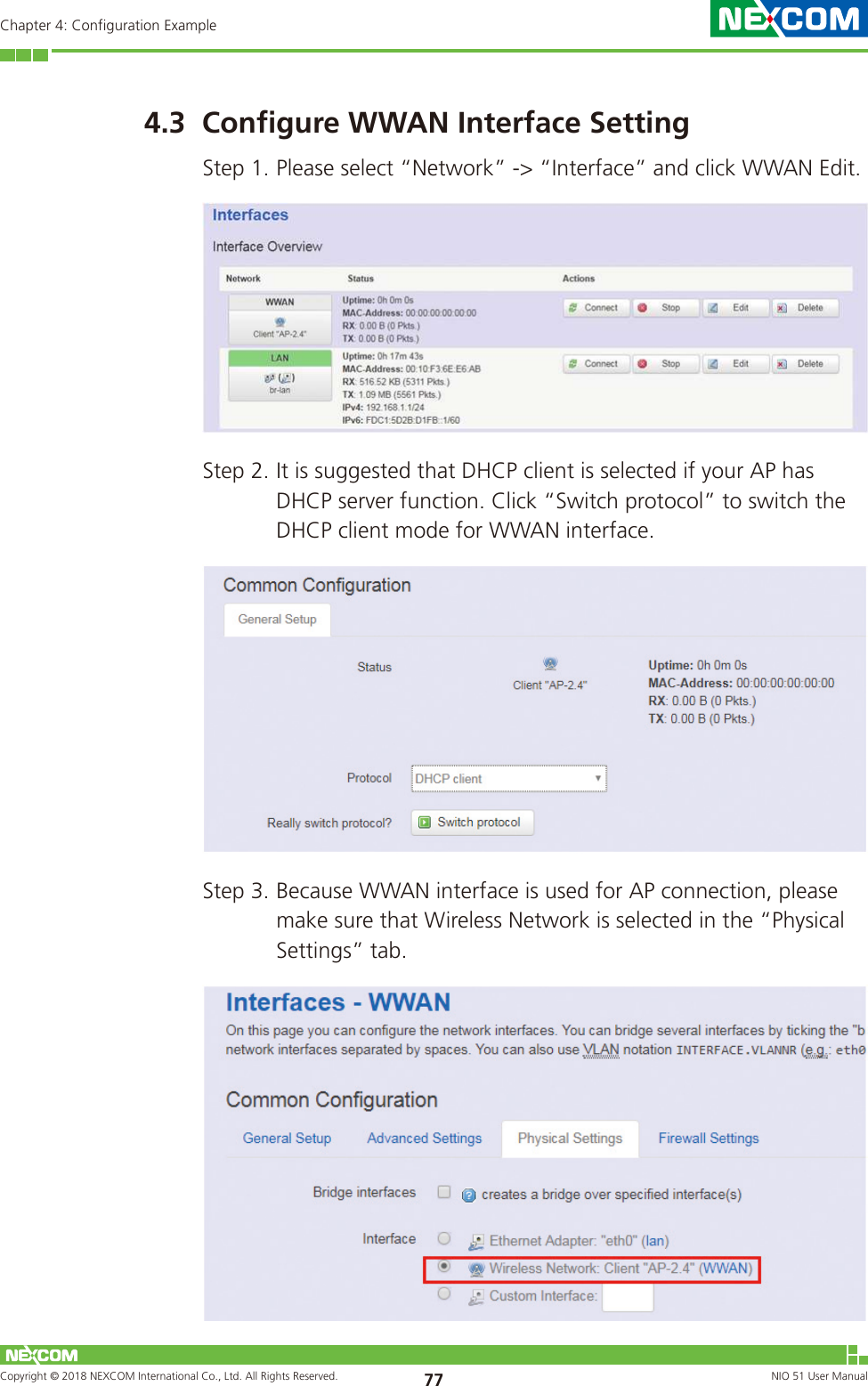
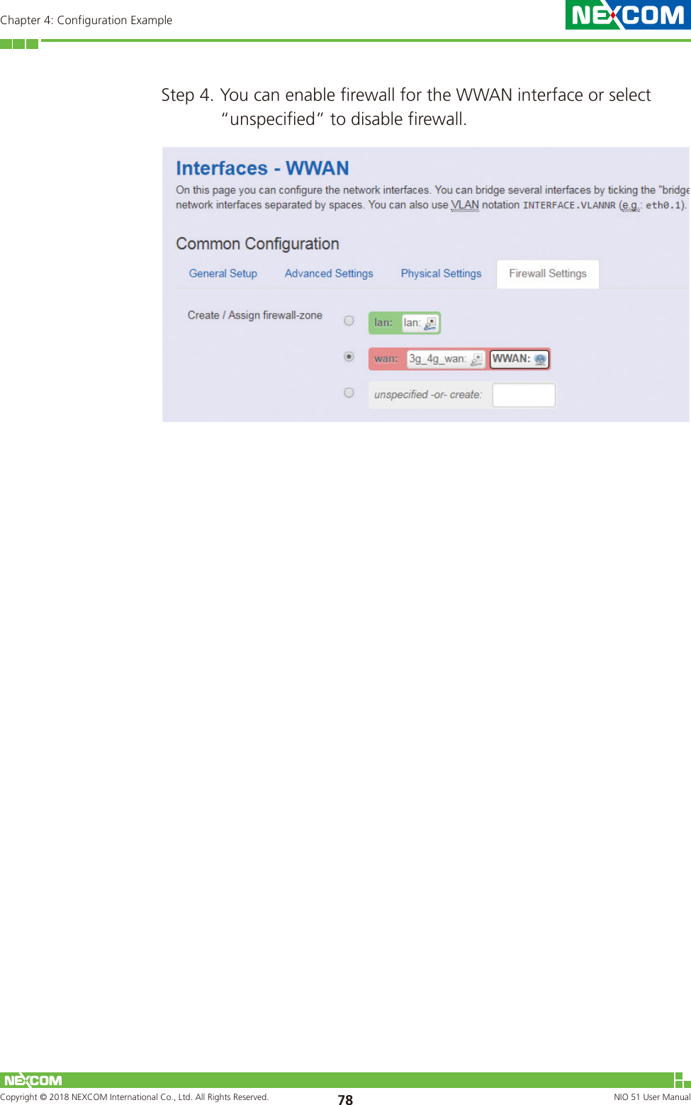
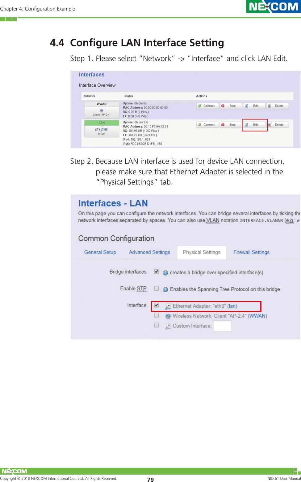
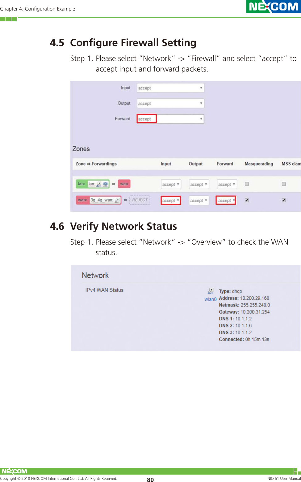
![Copyright © 2018 NEXCOM International Co., Ltd. All Rights Reserved. NIO 51 User Manual 51Chapter 2: System ConfigurationFor channel bandwidth, please note you need to confirm AP/client mode or mesh mode and the channel you will use.Transmit Power: Select the transmit power of a radio.<Advanced Settings>Distance Optimization: Specify the ACK timeout by entering the value manually. ACK timeout can be entered by defining the link distance. A value too short for the ACK timeout may cause transmission time out and no packets can be received. A value too long may cause low throughput rate.Fragmentation Threshold: Default=off. Specify the Fragmentation threshold by entering the value manually [300-2346 bytes]. This is the maximum size for a packet before data is fragmented into multiple packets. Setting the Fragmentation threshold too low may result in poor network performance. Only minor modifications of this value are recommended.](https://usermanual.wiki/NEXCOM/NIO51/User-Guide-3868349-Page-55.png)
![Copyright © 2018 NEXCOM International Co., Ltd. All Rights Reserved. NIO 51 User Manual 52Chapter 2: System ConfigurationRTS/CTS Threshold: Default=off. RTS/CTS (Request to Send / Clear to Send) is the optional mechanism used by the 802.11 wireless networking protocol to reduce frame collisions introduced by the hidden node problem. RTS/CTS is an additional method to implement virtual carrier sensing in Carrier sense multiple access with collision avoidance (CSMA/CA). Specify the RTS threshold by entering the value manually [0-2346 bytes]. Typically, sending RTS/CTS frames does not occur unless the packet size exceeds this threshold.The Interface Configuration section covers SSID operation mode and encryption.<General Setup>ESSID: Edit the SSID. The default SSID for radio0 is NIO51_11N and default SSID for radio1 is NIO51_11N_2G.Mode: Select the operation mode:• Client Router• 802.11s (Mesh mode)](https://usermanual.wiki/NEXCOM/NIO51/User-Guide-3868349-Page-56.png)