NEXCOM NIO51 Mesh Wi-Fi Device Gateway User Manual
NEXCOM international Co.,LTD Mesh Wi-Fi Device Gateway Users Manual
NEXCOM >
Users Manual

NEXCOM International Co., Ltd.
Version 1.0
Published March 2018
www.nexcom.com
NEXCOM International Co., Ltd.
IoT Automation Solutions Business Group
Industrial Mesh Wi-Fi Serial/Ethernet
Device Gateway
NIO 51
User Manual

Copyright © 2018 NEXCOM International Co., Ltd. All Rights Reserved. NIO 51 User Manual
ii
Contents
Contents
Preface ..................................................................... 1
Copyright ........................................................................................1
Disclaimer ........................................................................................1
Acknowledgements .........................................................................1
Regulatory Compliance Statements .................................................. 1
Declaration of Conformity ................................................................2
RoHS Compliance ............................................................................5
Safety Information ...........................................................................5
Installation Recommendations ..........................................................6
Safety Precautions ............................................................................ 6
Technical Support and Assistance .....................................................7
Conventions Used in this Manual .....................................................8
Chapter 1: Product Overview ................................. 9
1.1 Introduction ..............................................................................9
1.2 Panel Layout ...........................................................................11
1.2.1 NIO 51 Top Panel View ......................................................11
1.2.2 NIO 51 Dimension .............................................................12
1.3 LED Indicators .........................................................................13
1.4 Reset Button ...........................................................................13
1.5 Package Contents ...................................................................14
1.6 Power and Serial Port Pin Assignment .....................................15
Chapter 2: System Configuration ........................ 16
2.1 Quickly Access NIO 51 with Web Browser ...............................16
2.2 Status .....................................................................................19
2.2.1 Status ................................................................................19
2.2.2 Overview ........................................................................... 20
2.2.2.1 System .........................................................................20
2.2.2.2 Memory .......................................................................21
2.2.2.3 Network ......................................................................21
2.2.2.4 DHCP Leases ................................................................22

Copyright © 2018 NEXCOM International Co., Ltd. All Rights Reserved. NIO 51 User Manual
iii
Contents
2.2.2.5 DHCPv6 Leases ............................................................22
2.2.2.6 Wireless .......................................................................23
2.2.2.7 Associated Stations ......................................................23
2.2.3 Firewall .............................................................................24
2.2.4 Routes ...............................................................................25
2.2.4.1 ARP .............................................................................25
2.2.4.2 Active IPv4-Routes .......................................................25
2.2.4.3 Active IPv6-Routes .......................................................26
2.2.4.4 IPv6 Neighbors .............................................................26
2.2.5 System Log ........................................................................27
2.2.6 Kernel Log.........................................................................28
2.2.7 Processes ........................................................................... 29
2.2.8 Real-time Graphic ..............................................................29
2.2.8.1 Load ............................................................................30
2.2.8.2 Traffic ..........................................................................31
2.2.8.3 Wireless .......................................................................32
2.2.8.4 Connections ................................................................33
2.3 System .................................................................................... 34
2.3.1 System ..............................................................................35
2.3.1.1 General Settings ..........................................................35
2.3.1.2 Logging .......................................................................37
2.3.1.3 Language and Style .....................................................37
2.3.2 Administration ..................................................................38
2.3.2.1 Router Password ..........................................................38
2.3.2.2 SSH Access ..................................................................38
2.3.3 SNMP ................................................................................ 39
2.3.4 Backup/Flash Firmware ......................................................40
2.3.4.1 Upgrade Firmware .......................................................40
2.3.4.2 Backup Configuration ..................................................42
2.3.4.3 Reset to default ...........................................................43
2.3.7 Reboot ..............................................................................43
2.4 Network .................................................................................44
2.4.1 Interfaces ..........................................................................44
2.4.1.1 Change Default IP Address...........................................44
2.4.1.2 Interfaces Overview .....................................................45
2.4.1.3 LAN Interface Overview ...............................................46
2.4.1.4 DHCP Server ................................................................48

Copyright © 2018 NEXCOM International Co., Ltd. All Rights Reserved. NIO 51 User Manual
iv
Contents
2.4.2 WiFi ..................................................................................49
2.4.2.1 Wireless Overview ........................................................ 49
2.4.2.2 Associated Stations ......................................................50
2.4.2.3 Wireless Configuration ................................................50
2.4.3 DHCP and DNS ..................................................................55
2.4.4 Hostnames ........................................................................59
2.4.5 Static Routes .....................................................................60
2.4.6 RSTP ..................................................................................62
2.4.7 Firewall .............................................................................63
2.4.8 Diagnostics ........................................................................67
2.5 Modbus ..................................................................................68
2.5.1 Gateway ...........................................................................68
2.5.2 Log ...................................................................................70
Chapter 3: Product Specification .......................... 71
Chapter 4: Configuration Example ...................... 74
4.1 How to Configure 5G Mesh ....................................................74
4.2 How to Configure 2.4G Client Router .....................................75
4.3 Configure WWAN Interface Setting .........................................77
4.4 Configure LAN Interface Setting .............................................. 79
4.5 Configure Firewall Setting .......................................................80
4.6 Verify Network Status .............................................................80
4.7 How to Run Firmware Upgrade ...............................................81
4.8 How to Restore to Default Settings .........................................82
Chapter 5: Appendix ............................................. 83
5.1 Wi-Fi and 3G/4G Redundant Function ..................................... 83

Copyright © 2018 NEXCOM International Co., Ltd. All Rights Reserved. NIO 51 User Manual
1
Preface
This manual is for WLAN service providers or network administrators to set
up a network environment using the NIO 51 product line.
Copyright
This publication, including all photographs, illustrations and software, is
protected under international copyright laws, with all rights reserved. No
part of this manual may be reproduced, copied, translated or transmitted in
any form or by any means without the prior written consent from NEXCOM
International Co., Ltd.
Disclaimer
The information in this document is subject to change without prior notice
and does not represent commitment from NEXCOM International Co.,
Ltd. However, users may update their knowledge of any product in use by
constantly checking its manual posted on our website: http://www.nexcom.
com. NEXCOM shall not be liable for direct, indirect, special, incidental, or
consequential damages arising out of the use of any product, nor for any
infringements upon the rights of third parties, which may result from such
use. Any implied warranties of merchantability or fitness for any particular
purpose is also disclaimed.
Acknowledgements
The NIO series are trademarks of NEXCOM International Co., Ltd. All
other product names mentioned herein are registered trademarks of their
respective owners.
Regulatory Compliance Statements
This section provides the FCC compliance statement for Class B devices and
describes how to keep the system CE compliant.
PrefaCe

Copyright © 2018 NEXCOM International Co., Ltd. All Rights Reserved. NIO 51 User Manual
2
Preface
Declaration of Conformity
Federal Communication Commission Interference Statement
This equipment has been tested and found to comply with the limits for a
Class B digital device, pursuant to Part 15 of the FCC Rules. These limits are
designed to provide reasonable protection against harmful interference in
a residential installation. This equipment generates, uses and can radiate
radio frequency energy and, if not installed and used in accordance with
the instructions, may cause harmful interference to radio communications.
However, there is no guarantee that interference will not occur in a
particular installation. If this equipment does cause harmful interference
to radio or television reception, which can be determined by turning
the equipment off and on, the user is encouraged to try to correct the
interference by one of the following measures:
– Reorient or relocate the receiving antenna.
– Increase the separation between the equipment and receiver.
– Connect the equipment into an outlet on a circuit different from that
to which the receiver is connected.
– Consult the dealer or an experienced radio/TV technician for help.
FCC Caution: Any changes or modifications not expressly approved by the
party responsible for compliance could void the user's authority to operate
this equipment.
This device complies with Part 15 of the FCC Rules. Operation is subject
to the following two conditions: (1) This device may not cause harmful
interference, and (2) this device must accept any interference received,
including interference that may cause undesired operation.

Copyright © 2018 NEXCOM International Co., Ltd. All Rights Reserved. NIO 51 User Manual
3
Preface
IMPORTANT NOTE:
Radiation Exposure Statement:
This equipment complies with FCC radiation exposure limits set forth for an
uncontrolled environment. This equipment should be installed and operated
with minimum distance 20cm between the radiator and your body.
This transmitter must not be co-located or operating in conjunction with
any other antenna or transmitter.
Country Code selection feature to be disabled for products marketed to the
US/CANADA.
Operation of this device is restricted to indoor use only.
This device is intended only for OEM integrators under the following
conditions:
The antenna must be installed such that 20 cm is maintained between the
antenna and users.
The transmitter module may not be co-located with any other transmitter or
antenna.
For all products market in US, OEM has to limit the operation channels in
CH1 to CH11 for 2.4G band by supplied firmware programming tool. OEM
shall not supply any tool or info to the end-user regarding to Regulatory
Domain change.
As long as 3 conditions above are met, further transmitter test will not be
required. However, the OEM integrator is still responsible for testing their
end-product for any additional compliance requirements required with this
module installed.
IMPORTANT NOTE
In the event that these conditions can not be met (for example certain
laptop configurations or co-location with another transmitter), then the FCC
authorization is no longer considered valid and the FCC ID cannot be used
on the final product. In these circumstances, the OEM integrator will be
responsible for re-evaluating the end product (including the transmitter) and
obtaining a separate FCC authorization.

Copyright © 2018 NEXCOM International Co., Ltd. All Rights Reserved. NIO 51 User Manual
4
Preface
End Product Labeling
This transmitter module is authorized only for use in device where the
antenna may be installed such that 20 cm may be maintained between the
antenna and users.
Manual Information to the End User
The OEM integrator has to be aware not to provide information to the end
user regarding how to install or remove this RF module in the user’s manual
of the end product which integrates this module. The end user manual
shall include all required regulatory information/warning as shown in this
manual.
CE
The product(s) described in this manual complies with all applicable
European Union (CE) directives if it has a CE marking. For computer systems
to remain CE compliant, only CE-compliant parts may be used. Maintaining
CE compliance also requires proper cable and cabling techniques.

Copyright © 2018 NEXCOM International Co., Ltd. All Rights Reserved. NIO 51 User Manual
5
Preface
RoHS Compliance
NEXCOM RoHS Environmental Policy and Status Update
NEXCOM is a global citizen for building the digital
infrastructure. We are committed to providing green
products and services, which are compliant with European
Union RoHS (Restriction on Use of Hazardous Substance in Electronic
Equipment) directive 2011/65/EU, to be your trusted green partner
and to protect our environment. RoHS restricts the use of Lead (Pb)
< 0.1% or 1,000ppm, Mercury (Hg) < 0.1% or 1,000ppm, Cadmium
(Cd) < 0.01% or 100ppm, Hexavalent Chromium (Cr6+) < 0.1% or
1,000ppm, Polybrominated biphenyls (PBB) < 0.1% or 1,000ppm, and
Polybrominateddiphenyl Ethers (PBDE) < 0.1% or 1,000ppm. In order
to meet the RoHS compliant directives, NEXCOM has established an
engineering and manufacturing task force to implement the introduction
of green products. The task force will ensure that we follow the standard
NEXCOM development procedure and that all the new RoHS components
and new manufacturing processes maintain the highest industry quality
levels for which NEXCOM are renowned.
The model selection criteria will be based on market demand. Vendors and
suppliers will ensure that all designed components will be RoHS compliant.
How to recognize NEXCOM RoHS Products?
For existing products where there are non-RoHS and RoHS versions, the
suffix “(LF)” will be added to the compliant product name. All new product
models launched after January 2013 will be RoHS compliant. They will use
the usual NEXCOM naming convention.
Safety Information
Before installing and using the device, note the following precautions:
• Read all instructions carefully.
• Do not place the unit on an unstable surface, cart, or stand.
• Follow all warnings and cautions in this manual.
• When replacing parts, ensure that your service technician uses parts
specified by the manufacturer.
• Avoid using the system near water, in direct sunlight, or near a
heating device.

Copyright © 2018 NEXCOM International Co., Ltd. All Rights Reserved. NIO 51 User Manual
6
Preface
Installation Recommendations
Ensure you have a stable, clean working environment. Dust and dirt can get
into components and cause a malfunction. Use containers to keep small
components separated.
Adequate lighting and proper tools can prevent you from accidentally
damaging the internal components. Most of the procedures that follow
require only a few simple tools, including the following:
• A Philips screwdriver
• A flat-tipped screwdriver
• A grounding strap
• An anti-static pad
Using your fingers can disconnect most of the connections. It is
recommended that you do not use needle-nose pliers to disconnect
connections as these can damage the soft metal or plastic parts of the
connectors.
Safety Precautions
1. Read these safety instructions carefully.
2. Keep this User Manual for later reference.
3. Disconnect this equipment from any AC outlet before cleaning. Use a
damp cloth. Do not use liquid or spray detergents for cleaning.
4. For plug-in equipment, the power outlet socket must be located near the
equipment and must be easily accessible.
5. Keep this equipment away from humidity.
6. Put this equipment on a stable surface during installation. Dropping it or
letting it fall may cause damage.
7. The openings on the enclosure are for air convection to protect the
equipment from overheating. DO NOT COVER THE OPENINGS.
8. Make sure the voltage of the power source is correct before connecting
the equipment to the power outlet.
9. Place the power cord in a way so that people will not step on it. Do not
place anything on top of the power cord. Use a power cord that has
been approved for use with the product and that it matches the voltage
and current marked on the product’s electrical range label. The voltage
and current rating of the cord must be greater than the voltage and
current rating marked on the product.

Copyright © 2018 NEXCOM International Co., Ltd. All Rights Reserved. NIO 51 User Manual
7
Preface
10. All cautions and warnings on the equipment should be noted.
11. If the equipment is not used for a long time, disconnect it from the
power source to avoid damage by transient overvoltage.
12. Never pour any liquid into an opening. This may cause fire or electrical
shock.
13. Never open the equipment. For safety reasons, the equipment should
be opened only by qualified service personnel.
14. If one of the following situations arises, get the equipment checked by
service personnel:
a. The power cord or plug is damaged.
b. Liquid has penetrated into the equipment.
c. The equipment has been exposed to moisture.
d. The equipment does not work well, or you cannot get it to work
according to the user’s manual.
e. The equipment has been dropped and damaged.
f. The equipment has obvious signs of breakage.
15. Do not place heavy objects on the equipment.
16. CAUTION: DANGER OF EXPLOSION IF BATTERY IS INCORRECTLY
REPLACED. REPLACE ONLY WITH THE SAME OR EQUIVALENT TYPE
RECOMMENDED BY THE MANUFACTURER. DISCARD USED BATTERIES
ACCORDING TO THE MANUFACTURER’S INSTRUCTIONS.
Technical Support and Assistance
1. For the most updated information of NEXCOM products, visit NEXCOM’s
website at www.nexcom.com.
2. For technical issues that require contacting our technical support team or
sales representative, please have the following information ready before
calling:
– Product name and serial number
– Detailed information of the peripheral devices
– Detailed information of the installed software (operating system,
version, application software, etc.)
– A complete description of the problem
– The exact wordings of the error messages
Copyright © 2018 NEXCOM International Co., Ltd. All Rights Reserved. NIO 51 User Manual
8
Preface
Warnings
Read and adhere to all warnings, cautions, and notices in this guide
and the documentation supplied with the chassis, power supply, and
accessory modules. If the instructions for the chassis and power supply
are inconsistent with these instructions or the instructions for accessory
modules, contact the supplier to find out how you can ensure that your
computer meets safety and regulatory requirements.
1. Handling the unit: carry the unit with both hands and handle it with care.
2. Opening the enclosure: disconnect power before working on the unit to
prevent electrical shocks.
3. Maintenance: to keep the unit clean, use only approved cleaning
products or clean with a dry cloth.
Cautions
Electrostatic discharge (ESD) can damage system components. Do the
described procedures only at an ESD workstation.
If no such station is available, you can provide some ESD protection by
wearing an antistatic wrist strap and attaching it to a metal part of the
computer chassis.
Conventions Used in this Manual
Warning:
Information about certain situations, which if not observed, can
cause personal injury. This will prevent injury to yourself when
performing a task.
CAUTION!
CAUTION!CAUTION! Caution:
Information to avoid damaging components or losing data.
Note:
Provides additional information to complete a task easily.

Copyright © 2018 NEXCOM International Co., Ltd. All Rights Reserved. NIO 51 User Manual
9
Chapter 1: Product Overview
ChaPter 1: ProduCt overview
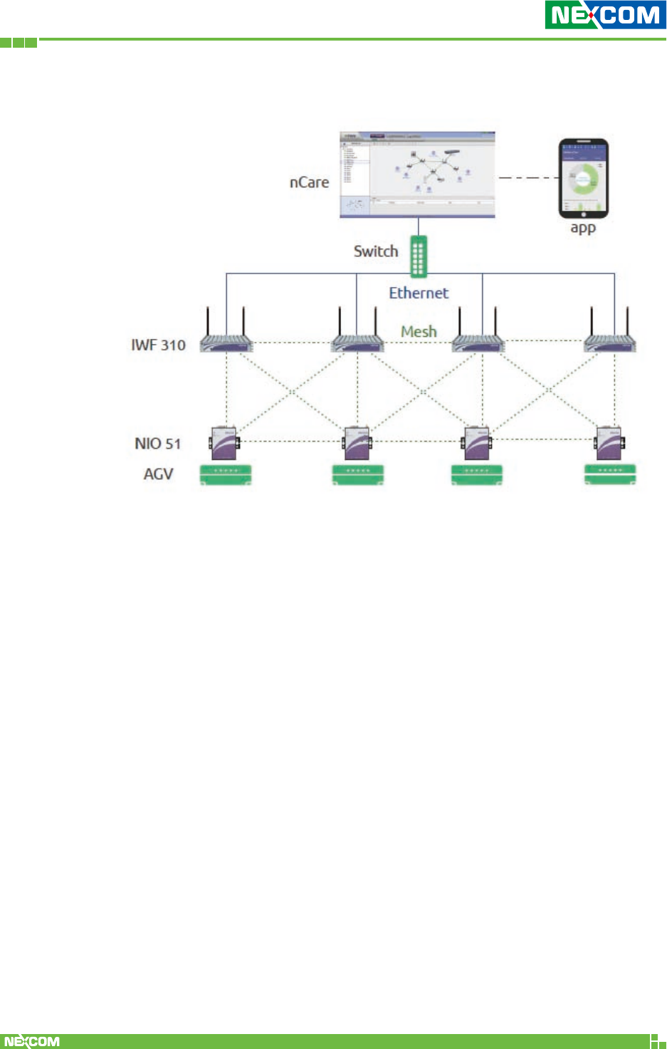
1.1 Introduction
NIO 51 brings the wireless connectivity from serial devices or Ethernet
devices perfectly to Wi-Fi Mesh in smart factories. Wi-Fi Mesh can be
used for device to AP or mesh backbone between APs.
NIO 51 supports a variety of operation modes and high immunity to
EMC high level protection, wide temperature and wide power range
for harsh environment.
NIO 51 can also be managed and discovered by nCare I4.0 network
manager. It’s a very competitive solution against other device
gateways in the market.
Key Features:
9IEEE 802.11a/b/g/n, 2X2 MIMO
9 Dual band 2.4GHz/5GHz
9 Support a variety of operation modes:
• Serial to Wireless (Mesh or Client)
• Serial to Ethernet
• Ethernet to Wireless
9 Support Modbus/TCP, Modbus/RTU
9 Offline serial port buffer with 20 MB of storage
9 High immunity to surge, ESD & EFT protection
(Surge: Level-3 / ESD, EFT : Level-4)
9 Wide DC power range with 12 - 48V
9 Wide operating temperature from -40°C to 70°C
9 Remote Management by nCare
Copyright © 2018 NEXCOM International Co., Ltd. All Rights Reserved. NIO 51 User Manual
10
Chapter 1: Product Overview
NIO 51 Mesh Application Scenarios
Copyright © 2018 NEXCOM International Co., Ltd. All Rights Reserved. NIO 51 User Manual
11
Chapter 1: Product Overview
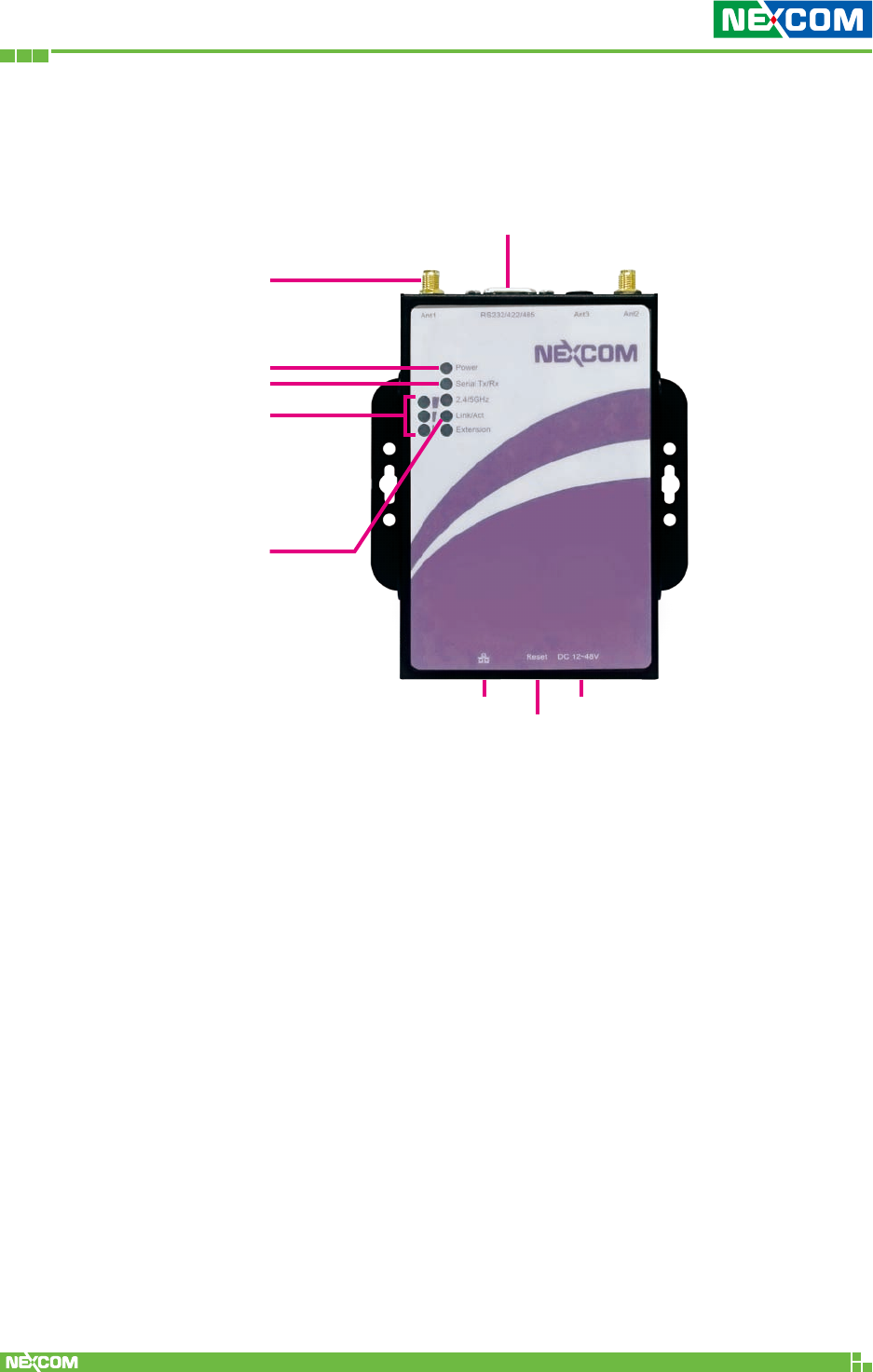
1.2 Panel Layout
1.2.1 NIO 51 Top Panel View
Wireless Signal
Strength
RS-232/422/485
Power LED
LAN Port
Reset
Serial LED
Antenna
LAN Port
LED
Terminal Block
Power Input
Copyright © 2018 NEXCOM International Co., Ltd. All Rights Reserved. NIO 51 User Manual
12
Chapter 1: Product Overview
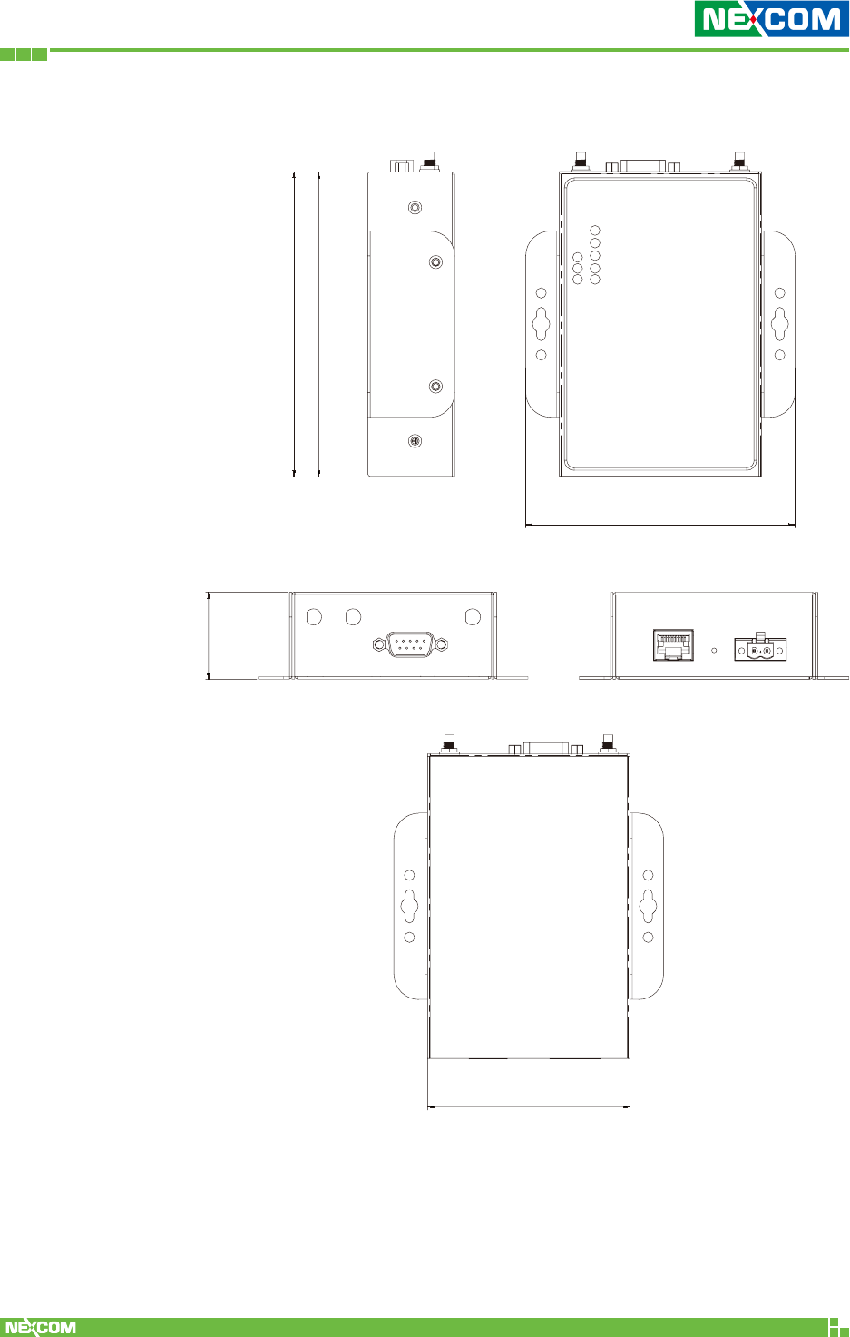
1.2.2 NIO 51 Dimension
122.80
122.60
108.60
35.00
81.40
Copyright © 2018 NEXCOM International Co., Ltd. All Rights Reserved. NIO 51 User Manual
13
Chapter 1: Product Overview
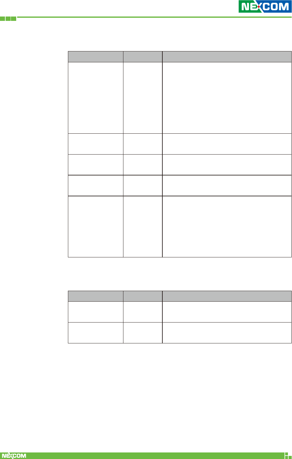
1.3 LED Indicators
Name Color Function
Power Green
Orange
Boot time is around 40 ~ 45s.
LED color changes when booting up:
Green (Steady on, 10s)
Orange (Steady on, 30s)
Green (Steady on, Ready)
Serial Tx/Rx Green
Red
Green: Tx, serial port to serial device.
Red: Rx, serial device to serial port.
2.4/5 GHz Green
Blue
Green: 2.4 GHz
Blue: 5 GHz
Link / Act Green Blinking: LAN port sending and
receiving data.
Signal Strength
(3 LEDs) Green
1 Green LED: The signal strength is
between 10% ~ 40%.
2 Green LEDs: The signal strength is
between 40% ~ 70%.
3 Green LEDs: The signal strength is
between 70% ~ 100%.
1.4 Reset Button
Name Color Function
Reboot 3 ~ 10s LED Color Change:
Green -> Orange -> Boot up
Reset to default X > 10s Green -> Orange (flash once) -> Green
-> Orange -> Boot up
Copyright © 2018 NEXCOM International Co., Ltd. All Rights Reserved. NIO 51 User Manual
14
Chapter 1: Product Overview
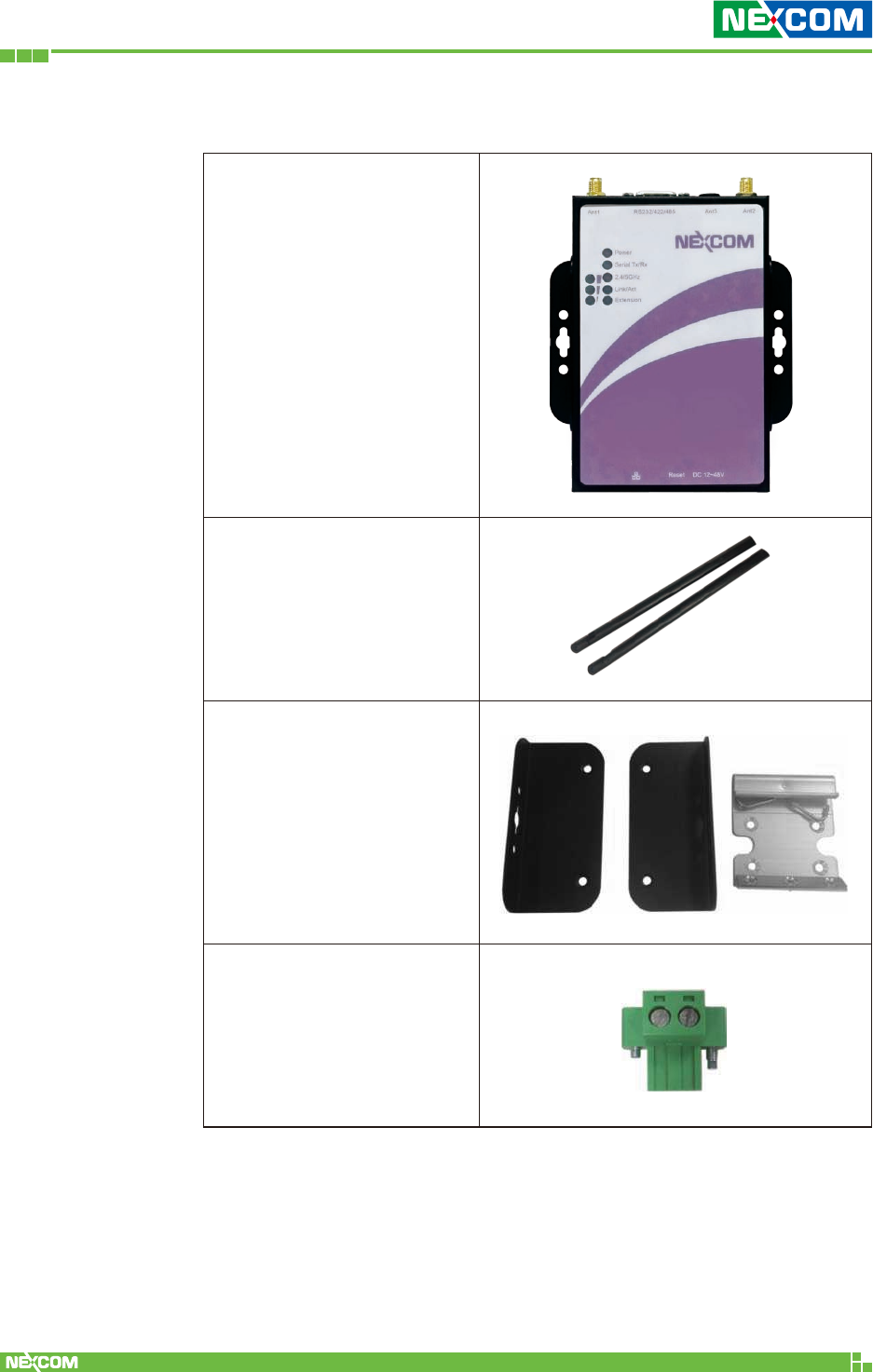
1.5 Package Contents
NIO 51 unit x 1
Dual band antenna x 2
Wall-mount kit x 1
DIN-Rail kit x 1
Terminal Block
Connector x 1
Copyright © 2018 NEXCOM International Co., Ltd. All Rights Reserved. NIO 51 User Manual
15
Chapter 1: Product Overview
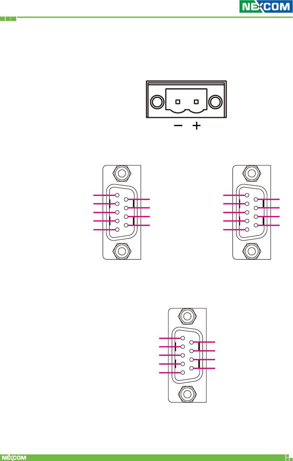
1.6 Power and Serial Port Pin Assignment
Terminal Block Power Input
1 5
6 9
1 5
6 9
RS-485 Pin Assignment
RxD
D+ (Data+)
D- (Data-)
TxD
GND
CTS
RTS
1
1
6
6
7
7
8
8
9
9
2
2
3
3
4
4
5
5
RS-232 Pin Assignment RS-422 Pin Assignment
1 5
6 9
16
7
8
9
2
3
4
5
TX-
TX+
RX-
RX+
Copyright © 2018 NEXCOM International Co., Ltd. All Rights Reserved. NIO 51 User Manual
16
Chapter 2: System Configuration
ChaPter 2: system Configuration
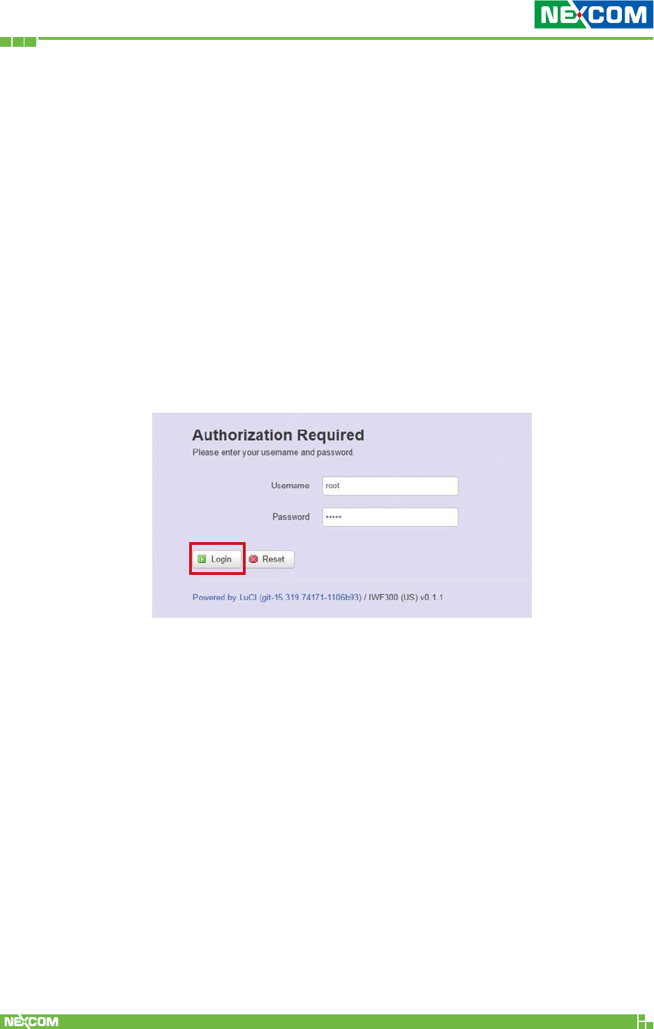
2.1 Quickly Access NIO 51 with Web Browser
Login
To access the NIO 51 device, you can open a web browser to access
the Web GUI via the default IP address 192.168.1.1
The default administrator login settings are:
Login: root
Password: admin
The first page you would is see the login page like the below screenshot:
Copyright © 2018 NEXCOM International Co., Ltd. All Rights Reserved. NIO 51 User Manual
17
Chapter 2: System Configuration
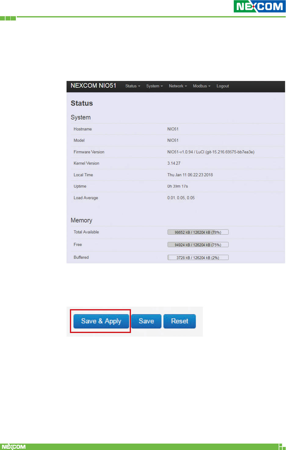
After successful login you will see the “Status” page of the web
management interface with current information of System, Memory,
Network, DHCP, Wireless, and Associated Stations. The device now is
ready for configuration.
Saving Changes
“Save & Apply” the configuration at the bottom of the Web GUI after
you change the settings.
Copyright © 2018 NEXCOM International Co., Ltd. All Rights Reserved. NIO 51 User Manual
18
Chapter 2: System Configuration
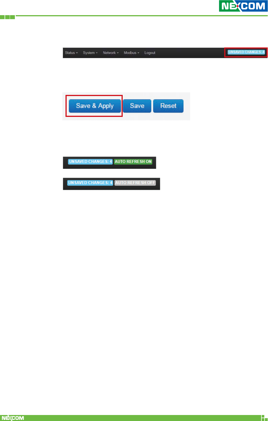
Unsaved Changes
“UNSAVED CHANGES” provides the information to see the parameters
which were not saved and applied.
Click the “Save & Apply” button to save the parameters.
Auto Refresh
Click the “AUTO REFRESH” button to turn on/off the automatic Web
GUI refresh function.
Copyright © 2018 NEXCOM International Co., Ltd. All Rights Reserved. NIO 51 User Manual
19
Chapter 2: System Configuration
2.2 Status
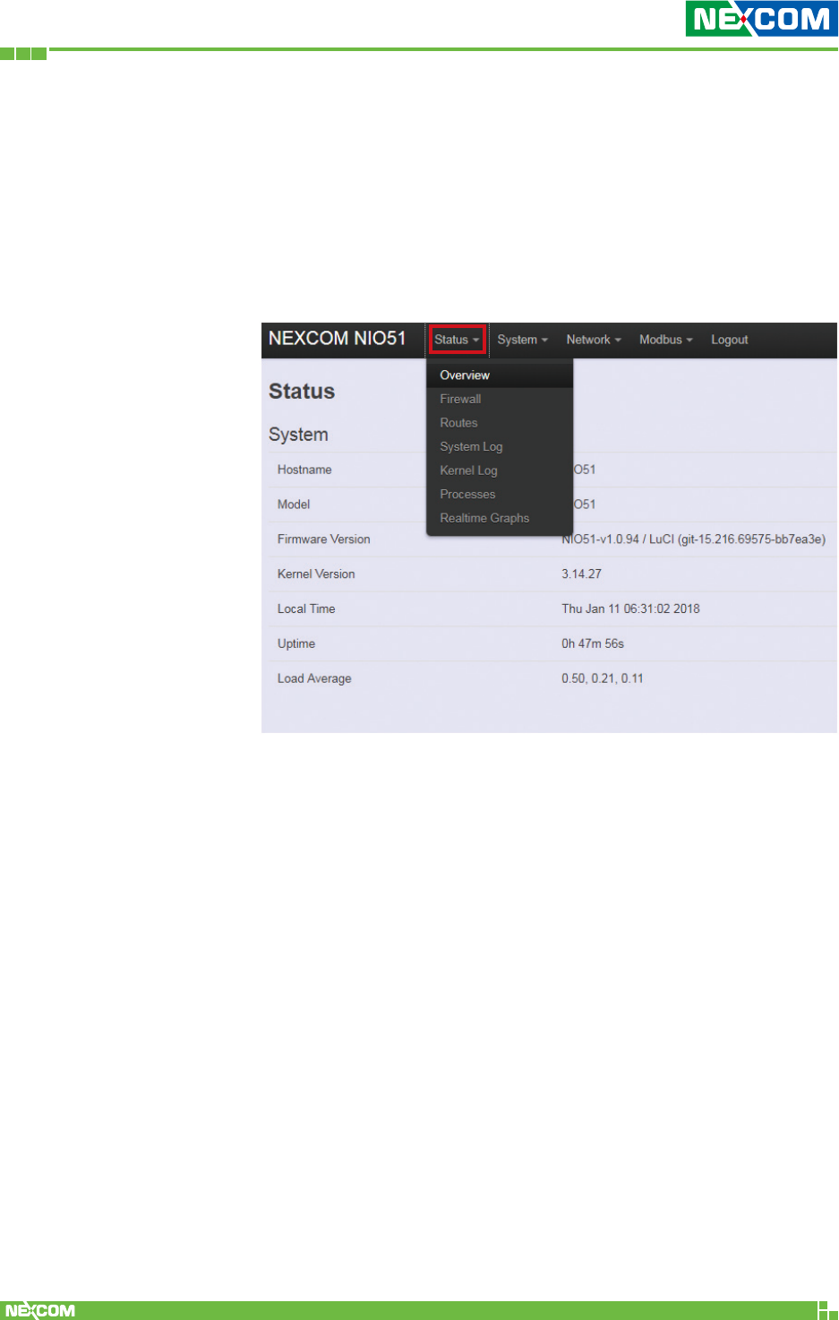
2.2.1 Status
To display more detailed status, you can click the “Status”
menu under the menu bar, then select the item of Overview,
Firewall, Routes, System Log, Kernel Log, Process, and Real-
time Graphs from the pull-down list like the below screen:
Copyright © 2018 NEXCOM International Co., Ltd. All Rights Reserved. NIO 51 User Manual
20
Chapter 2: System Configuration
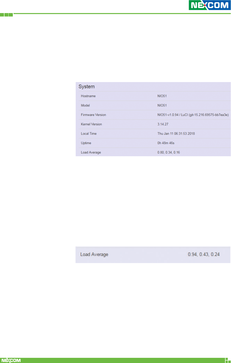
Hostname: Displays NIO 51 name.
Model: Displays NIO 51 HW basic information.
Firmware Version: Displays NIO 51 firmware version.
Kernel Version: Displays NIO 51 current kernel version.
Local Time: Displays NIO 51 current date and time.
Uptime: Displays how long NIO 51 has been
operating since last boot-up uptime.
Load Average: CPU average loading.
For example:
CPU average loading: 94% in the past 1 minute.
43% in the past 5 minutes.
24% in the past 15 minutes.
2.2.2 Overview
To see the overall status of NIO 51, click “Overview” to display
system information and the current settings of the NIO 51’s
ports.
2.2.2.1 System
Copyright © 2018 NEXCOM International Co., Ltd. All Rights Reserved. NIO 51 User Manual
21
Chapter 2: System Configuration
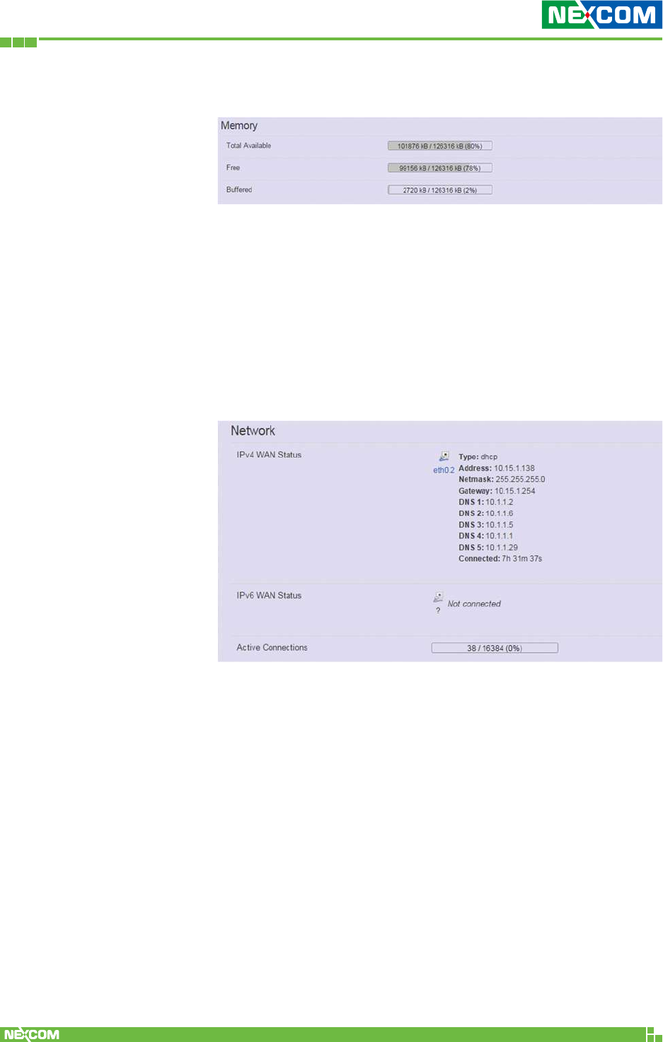
2.2.2.2 Memory
Total Available: Displays NIO 51 current available
memory.
Free: Displays NIO 51 current free memory.
Buffered: Displays NIO 51 memory used for
buffering.
IPv4 WAN Status: Displays current IPv4 connection
information.
IPv6 WAN Status: Displays current IPv6 connection
information.
Active Connections: Displays current active connections.
2.2.2.3 Network
Copyright © 2018 NEXCOM International Co., Ltd. All Rights Reserved. NIO 51 User Manual
22
Chapter 2: System Configuration
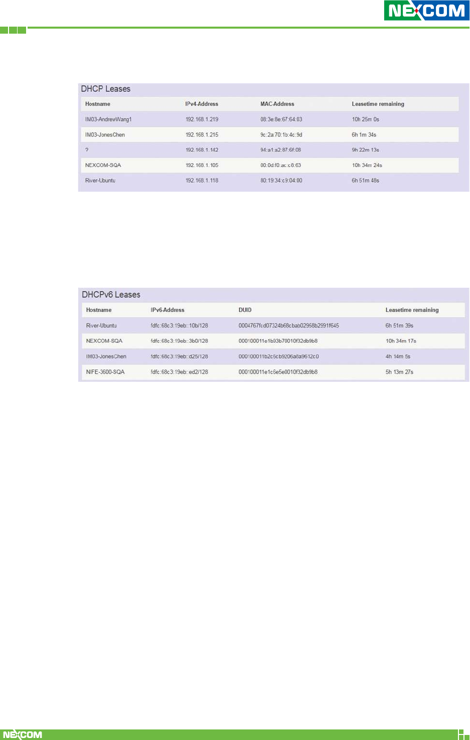
2.2.2.4 DHCP Leases
This displays information about hosts (personal computers or electronic
devices) that are connected to NIO 51 including IPv4, MAC address and
leasing time
2.2.2.5 DHCPv6 Leases
This displays information about hosts (personal computers or electronic
devices) that are connected to NIO 51 including IPv6, DUID and leasing
time.
Copyright © 2018 NEXCOM International Co., Ltd. All Rights Reserved. NIO 51 User Manual
23
Chapter 2: System Configuration
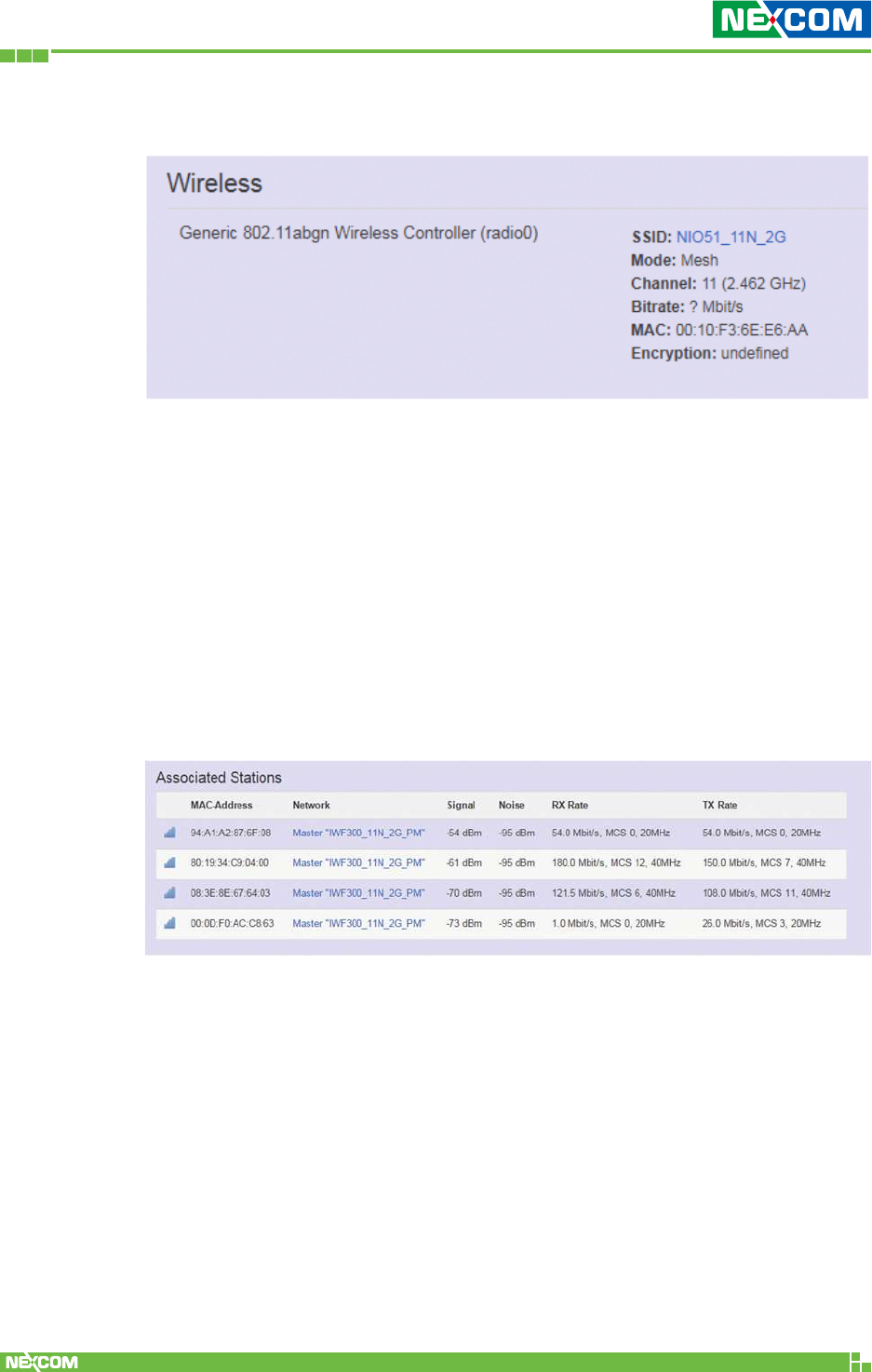
2.2.2.6 Wireless
This displays wireless information about NIO 51.
SSID: Displays the name of the wireless network.
Mode: Displays the mode in this radio.
Channel: Displays current channel used.
Bitrate: Displays current wireless data rate.
MAC: Displays MAC address of this radio.
Encryption: Displays current encryption setting.
2.2.2.7 Associated Stations
Displays current associated device information (personal computers or
electronic devices) with NIO 51, including device’s MAC address, signal level,
noise and connecting data rate.
Copyright © 2018 NEXCOM International Co., Ltd. All Rights Reserved. NIO 51 User Manual
24
Chapter 2: System Configuration
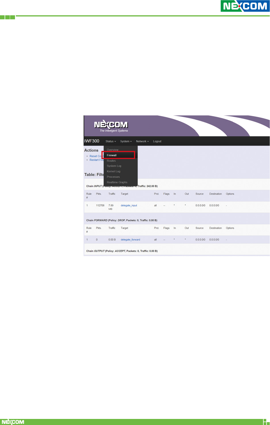
2.2.3 Firewall
Firewall setting is a particular function which allows user
to connect or block two or more interfaces in device with
sophisticated and specifically defined parameters in this Web
page.
The settings in Firewall are suggested to keep it as factory
default.
Copyright © 2018 NEXCOM International Co., Ltd. All Rights Reserved. NIO 51 User Manual
25
Chapter 2: System Configuration
2.2.4 Routes
This section displays information about routing list for current
connected device.
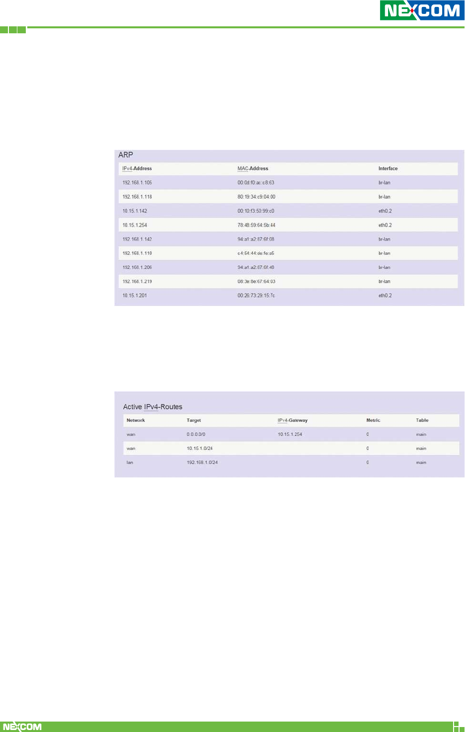
2.2.4.1 ARP
Displays ARP information in NIO 51 including IPv4 address, MAC
address and connecting interface.
2.2.4.2 Active IPv4-Routes
Displays active WAN and LAN port’s IPv4 routing table.
Copyright © 2018 NEXCOM International Co., Ltd. All Rights Reserved. NIO 51 User Manual
26
Chapter 2: System Configuration
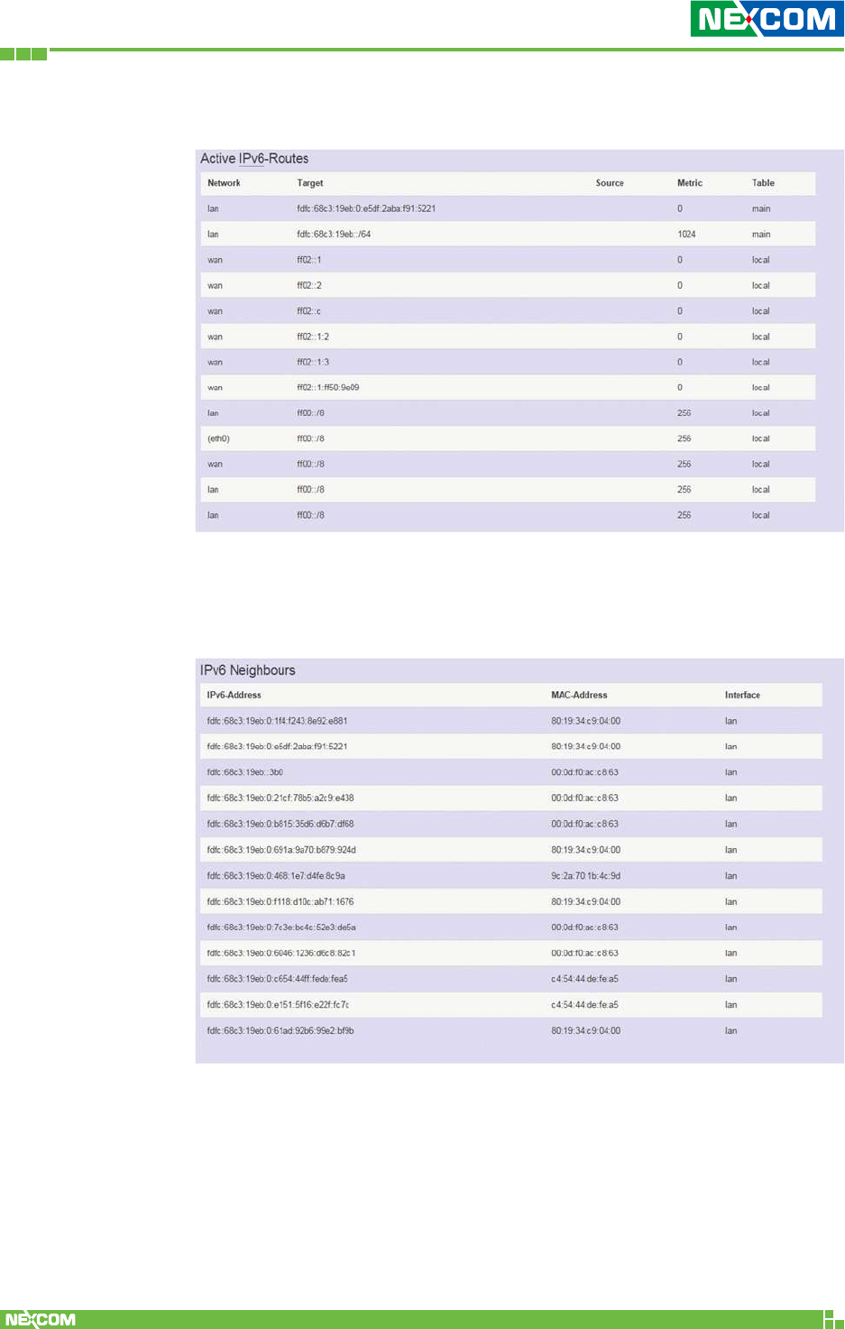
2.2.4.3 Active IPv6-Routes
2.2.4.4 IPv6 Neighbors
Displays active IPv6 routing table of WAN and LAN port.
Displays connected device with IPv6 information.
Copyright © 2018 NEXCOM International Co., Ltd. All Rights Reserved. NIO 51 User Manual
27
Chapter 2: System Configuration
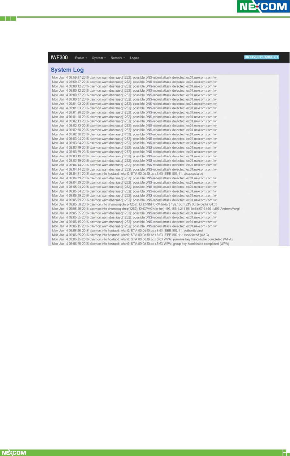
2.2.5 System Log
Displays the record of system activities. The administrator can monitor the
system status by checking this log.
Copyright © 2018 NEXCOM International Co., Ltd. All Rights Reserved. NIO 51 User Manual
28
Chapter 2: System Configuration
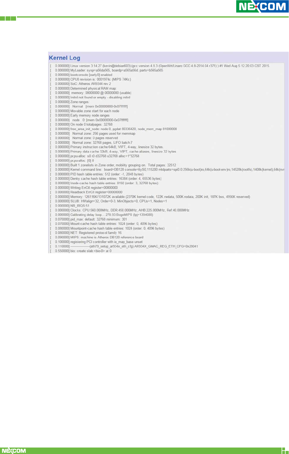
2.2.6 Kernel Log
Displays the record of kernel activities. The administrator can monitor the
system status by checking this log.
Copyright © 2018 NEXCOM International Co., Ltd. All Rights Reserved. NIO 51 User Manual
29
Chapter 2: System Configuration
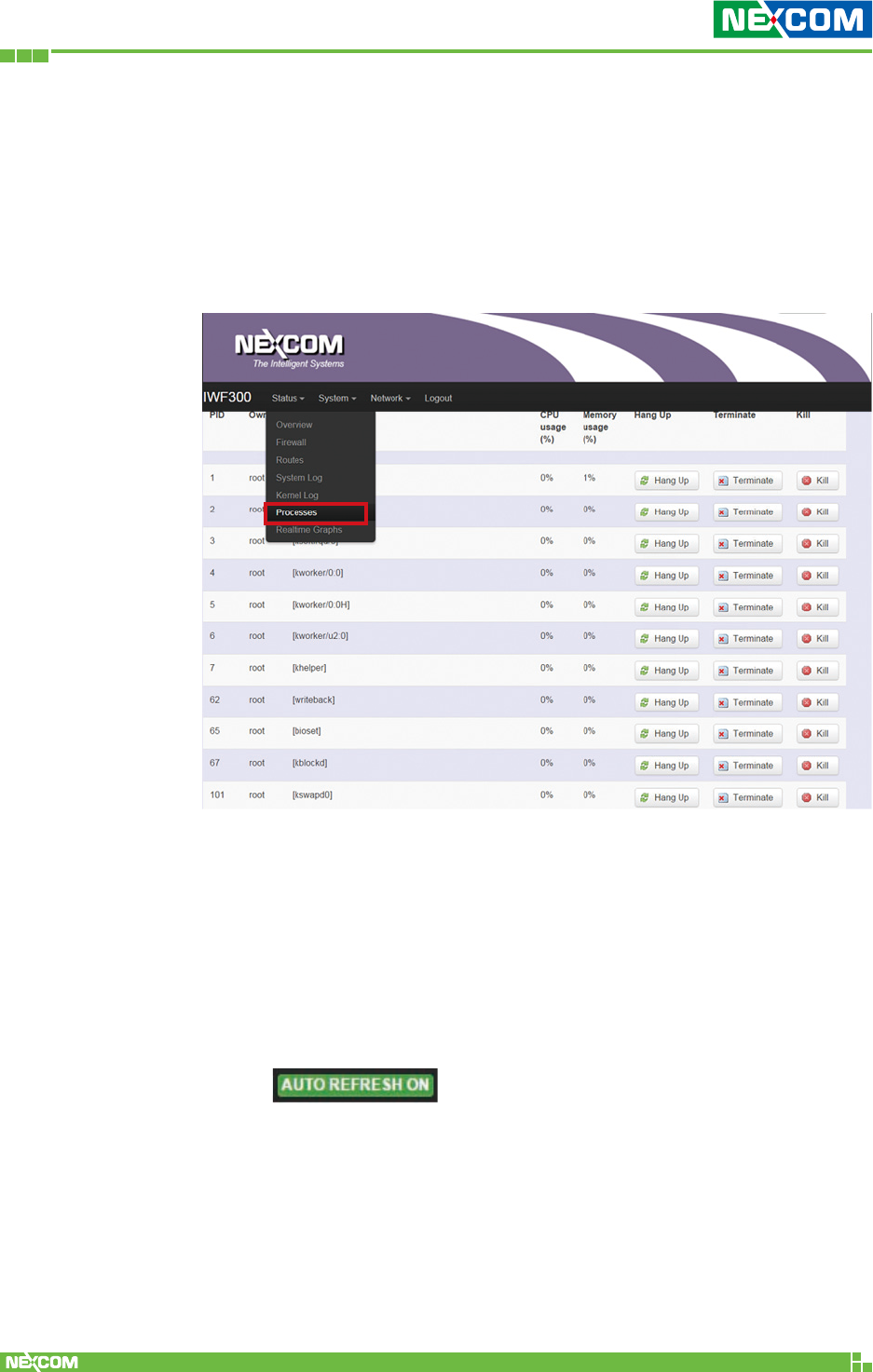
2.2.7 Processes
This Webpage is designed for detailed troubleshooting/
status monitoring by professional personnel in the field. Any
improper termination or killing of individual process tasks may
cause device malfunction. It is suggested that the settings
are kept as factory default.
2.2.8 Real-time Graphic
This section provides utilities to monitor NIO 51 system
information including real-time load, real-time Ethernet traffic,
real-time wireless signal and real-time associated device traffic.
To monitor status in this section, please make sure the Web
GUI “auto refresh” function must be “turn on”.
Copyright © 2018 NEXCOM International Co., Ltd. All Rights Reserved. NIO 51 User Manual
30
Chapter 2: System Configuration
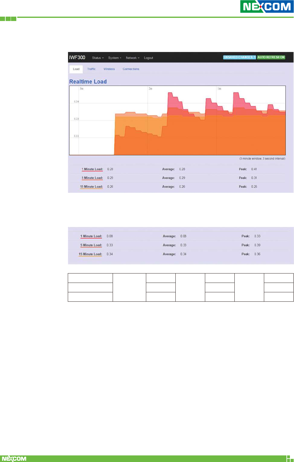
2.2.8.1 Load
Displays real-time CPU average loading percentage.
For example:
1 minute
Minimum
8%
Average
8%
Peak
33%
5 minutes 33% 33% 39%
15 minutes 34% 34% 36%
Copyright © 2018 NEXCOM International Co., Ltd. All Rights Reserved. NIO 51 User Manual
31
Chapter 2: System Configuration
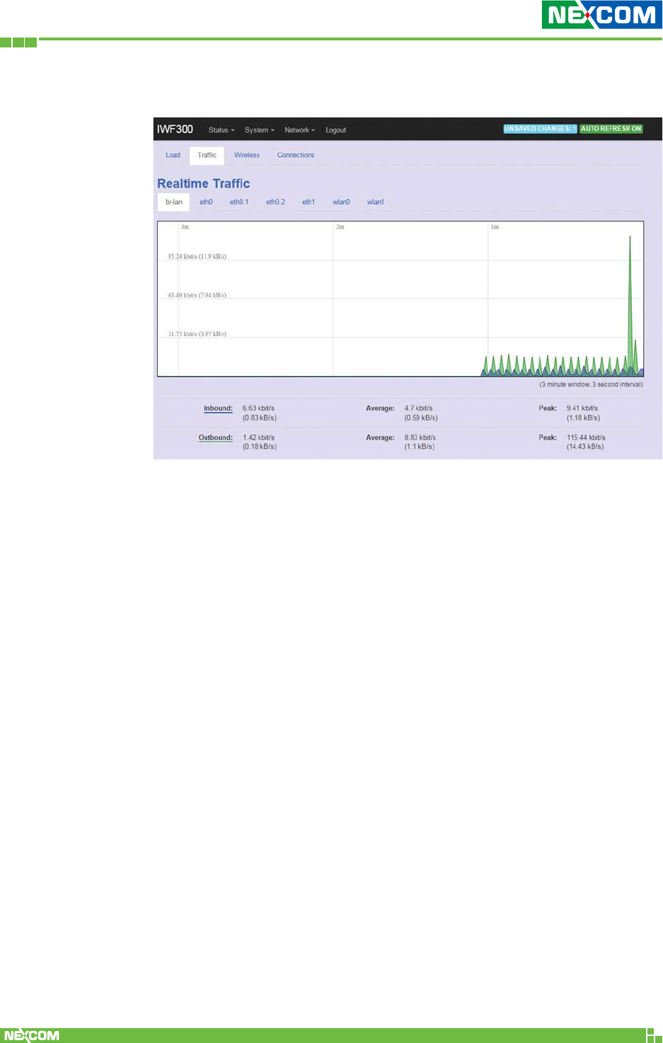
2.2.8.2 Traffic
Displays NIO 51 Ethernet real-time traffic loading.
Inbound: Incoming data packet size.
Outbound: Outgoing data packet size.
Copyright © 2018 NEXCOM International Co., Ltd. All Rights Reserved. NIO 51 User Manual
32
Chapter 2: System Configuration
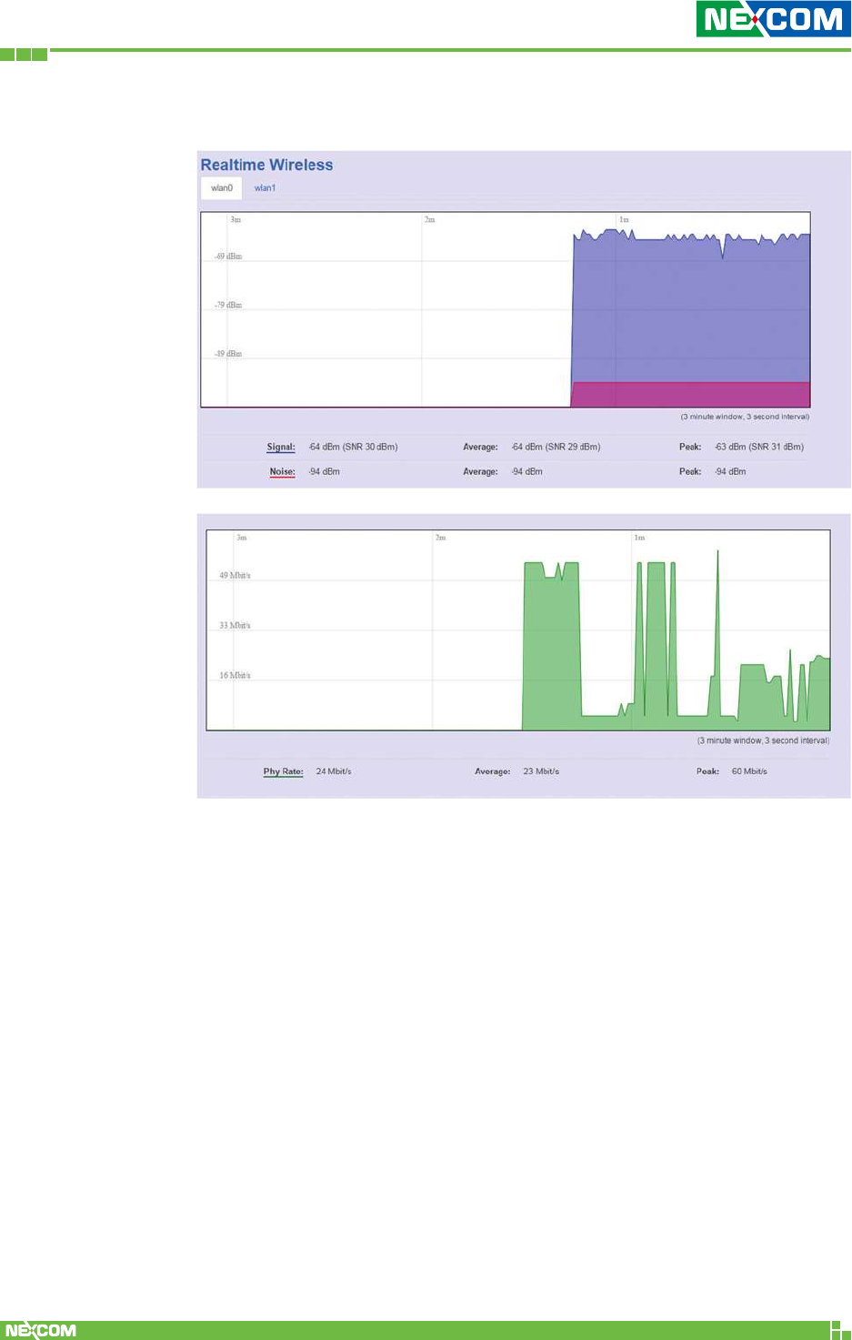
2.2.8.3 Wireless
Displays wireless real-time signal quality including signal level, noise
and data rate.
Copyright © 2018 NEXCOM International Co., Ltd. All Rights Reserved. NIO 51 User Manual
33
Chapter 2: System Configuration
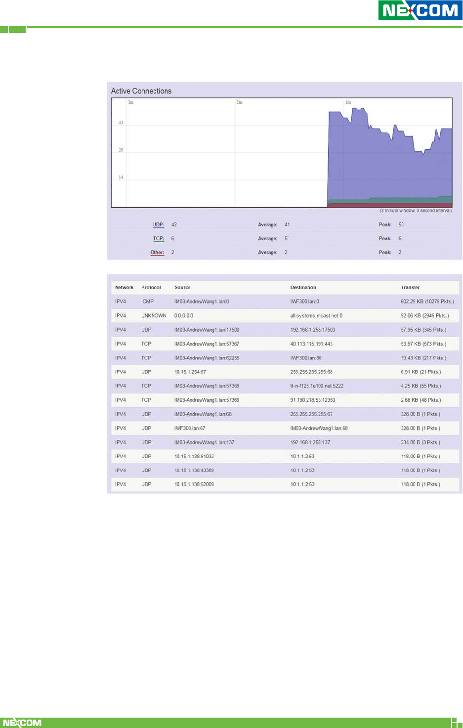
2.2.8.4 Connections
Displays NIO 51 real-time active connection information, including
TCP and UDP connections.
Copyright © 2018 NEXCOM International Co., Ltd. All Rights Reserved. NIO 51 User Manual
34
Chapter 2: System Configuration
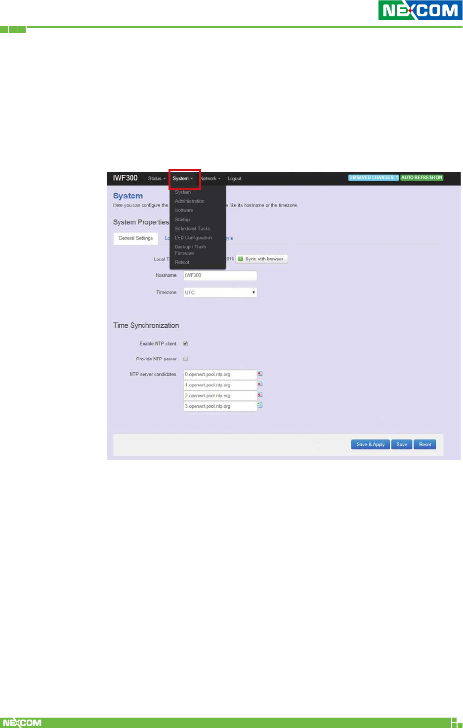
2.3 System
To set up detailed configuration about the NIO 51 system, click
the “System” under the menu bar, then select the items such as
System, Administration, Software, Start up, Scheduled Tasks, LED
configuration, Backup/Flash Firmware and Reboot from the pull-down
list like the below screen:
Copyright © 2018 NEXCOM International Co., Ltd. All Rights Reserved. NIO 51 User Manual
35
Chapter 2: System Configuration
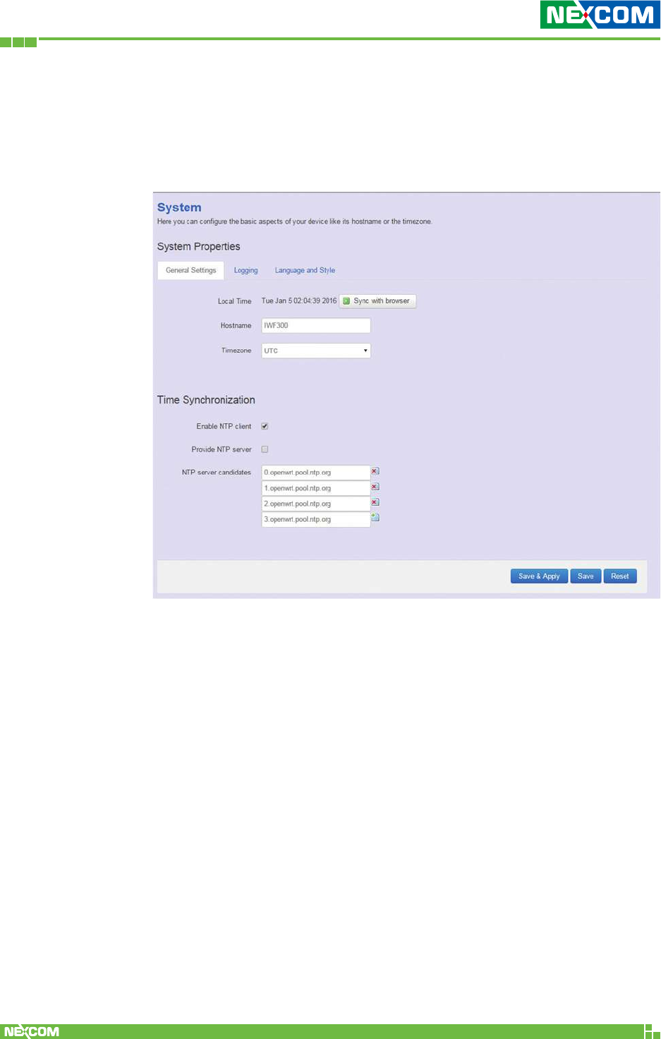
2.3.1 System
2.3.1.1 General Settings
This section provides general settings of NIO 51 including
Time, Host name, Time zone and NTP.
Copyright © 2018 NEXCOM International Co., Ltd. All Rights Reserved. NIO 51 User Manual
36
Chapter 2: System Configuration
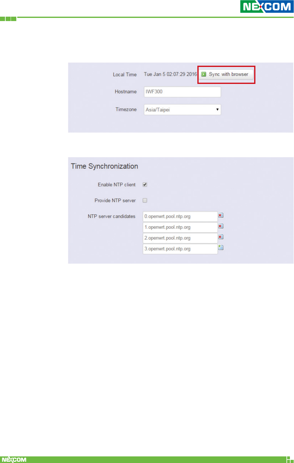
Enter the address of an SNTP server to receive time updates.
Click “Sync with browser” and let NIO 51 sync time with your current
computer, then select your country from the Timezone pull-down list.
Copyright © 2018 NEXCOM International Co., Ltd. All Rights Reserved. NIO 51 User Manual
37
Chapter 2: System Configuration
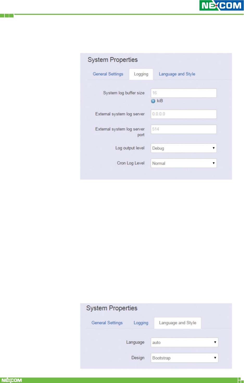
2.3.1.2 Logging
This section provides settings for log configuration.
System log buffer size: The size of log information. Unit: Kbytes.
External system log server: The server address of external log
server.
External system log server port: The port number of external
log server.
Log output level: The output information of log, including
Debug, Info, Notice, Warring, Error, Critical, Alert, and Emergency.
Cron Log Level: The minimal level for cron messages to be logged
to syslog.
2.3.1.3 Language and Style
This section provides settings for language and Web GUI
style. NIO 51 only provides English as default and NEXCOM
style of Web GUI.
Copyright © 2018 NEXCOM International Co., Ltd. All Rights Reserved. NIO 51 User Manual
38
Chapter 2: System Configuration
2.3.2 Administration
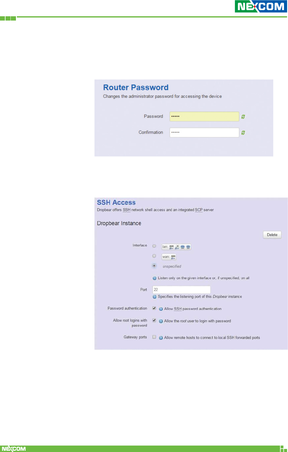
2.3.2.1 Router Password
To change the default password, enter the new password
and confirm it.
2.3.2.2 SSH Access
Secure Shell (SSH). Enable your NIO 51 to be accessed via
SSH-based application.
Interface: Select the interface.
Port: Enter the port number.
Password authentication: Enable/Disable SSH password
authentication.
Allow root logins with password: Enable/Disable the root
user to login with password.
Gateway ports: Enable/Disable remote hosts to connect to
local SSH forwarded ports.
Copyright © 2018 NEXCOM International Co., Ltd. All Rights Reserved. NIO 51 User Manual
39
Chapter 2: System Configuration
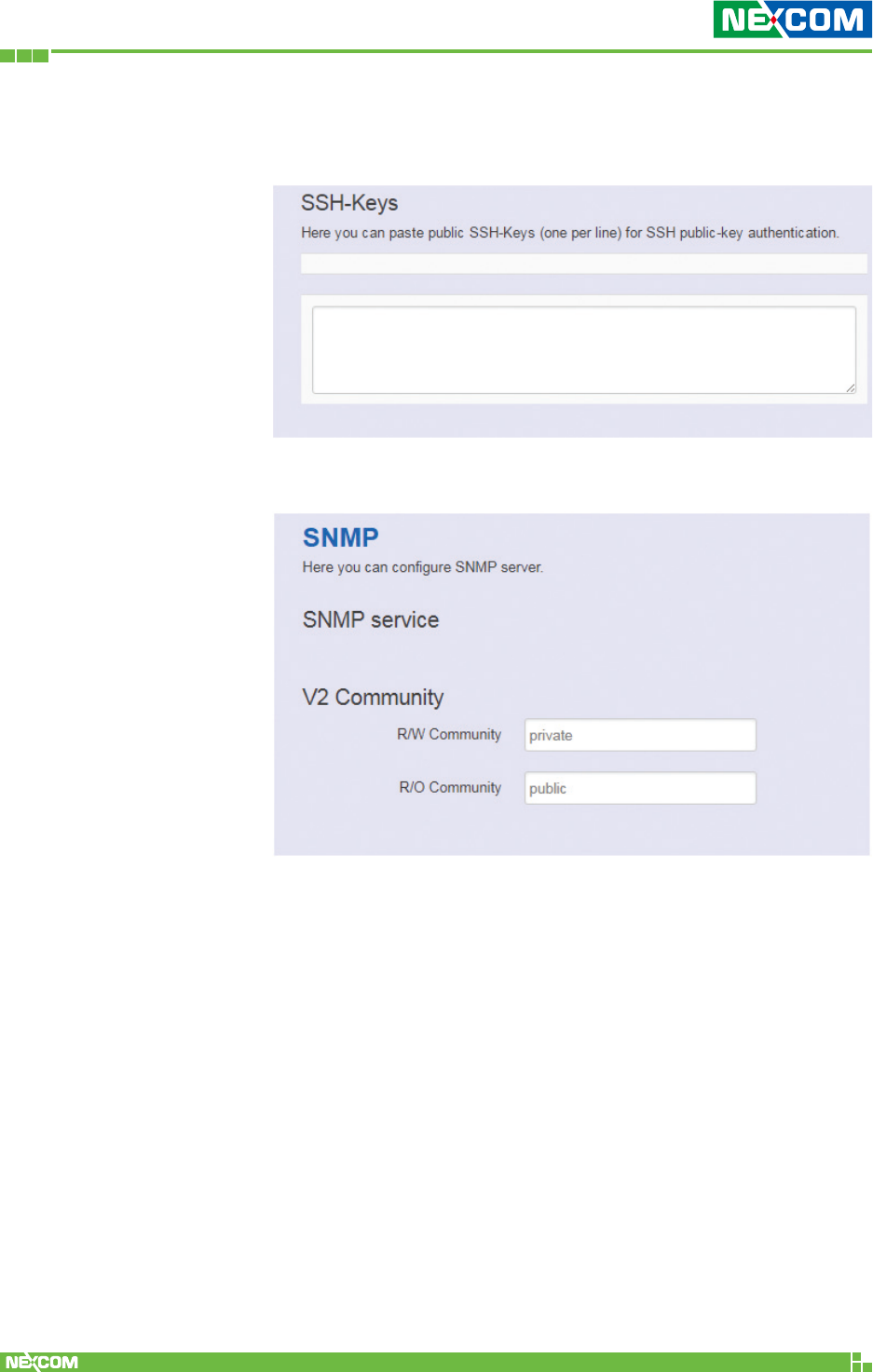
Paste public SSH-Keys (one per line) for SSH public-key
authentication.
R/W Community: SNMP Read-Write Community String -
Used in requests for information from a device and to modify
settings on that device.
R/O Community: SNMP Read-Only Community String -
Enables a remote device to retrieve “read-only” information
from a device.
2.3.3 SNMP
Copyright © 2018 NEXCOM International Co., Ltd. All Rights Reserved. NIO 51 User Manual
40
Chapter 2: System Configuration
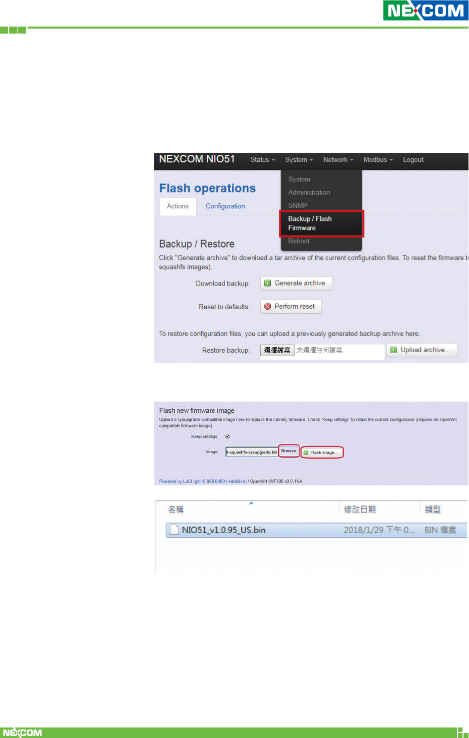
2.3.4 Backup/Flash Firmware
2.3.4.1 Upgrade Firmware
To upgrade a new firmware onto the device, please select
“System” from the menu bar, and then select “Backup/Flash
Firmware”.
Please click “Browse” to select the new firmware.
Copyright © 2018 NEXCOM International Co., Ltd. All Rights Reserved. NIO 51 User Manual
41
Chapter 2: System Configuration
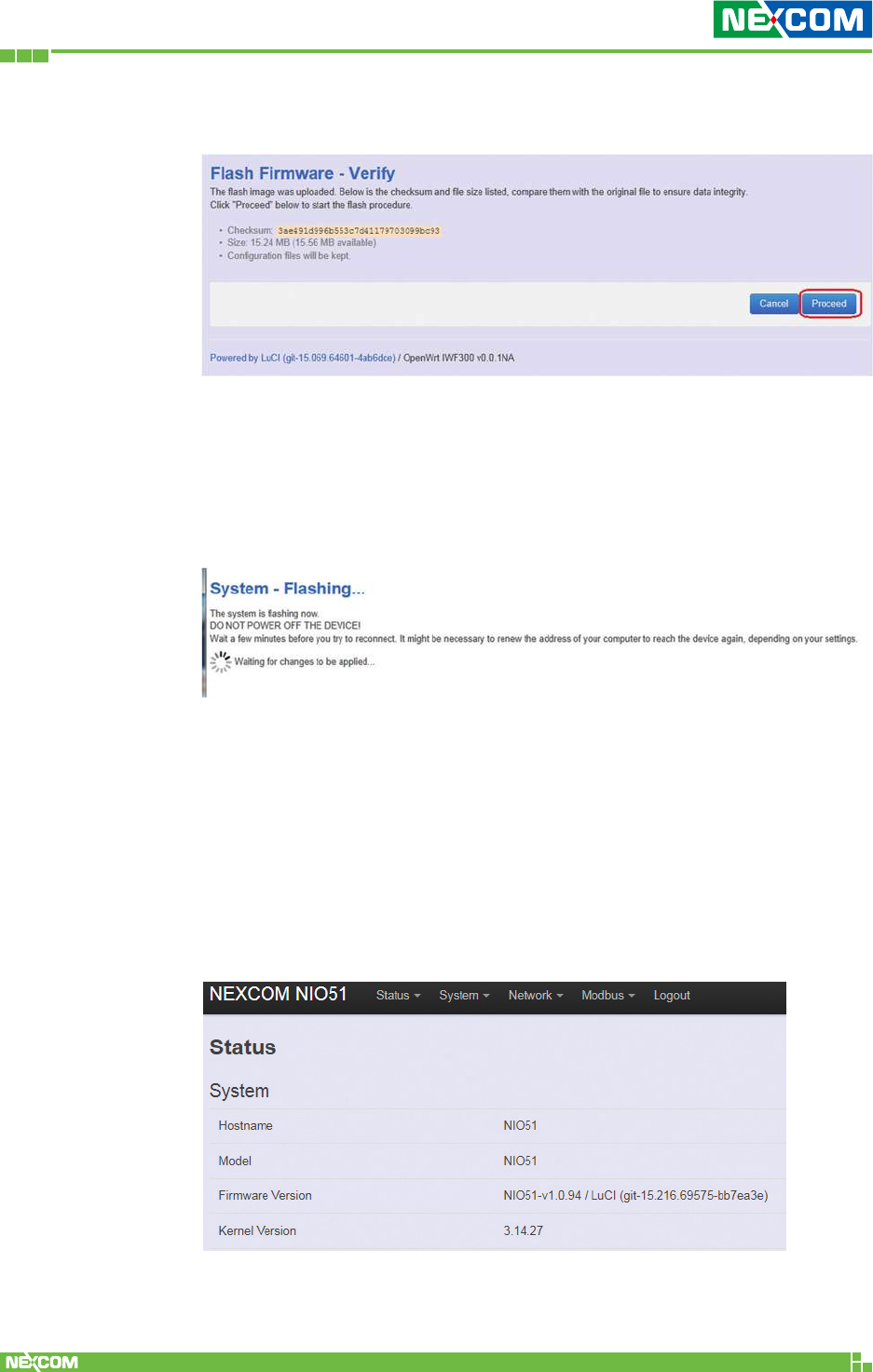
Then the GUI will display the file checksum.
Click “Proceed” to start the upgrade process.
Note: After you click “Proceed”, the DUT firmware will be upgraded
with the file you selected, and the upgrade progress will be displayed
like below:
Note: The whole programming might take several minutes to
complete the flash writing. PLEASE DO NOT REBOOT OR POWER OFF
THE DEVICE before the whole progress completes.
If the firmware upgrade is successful, the GUI should switch to the
Login page.
You can also check the version via the “Firmware Version” field under
the Status page.
Copyright © 2018 NEXCOM International Co., Ltd. All Rights Reserved. NIO 51 User Manual
42
Chapter 2: System Configuration
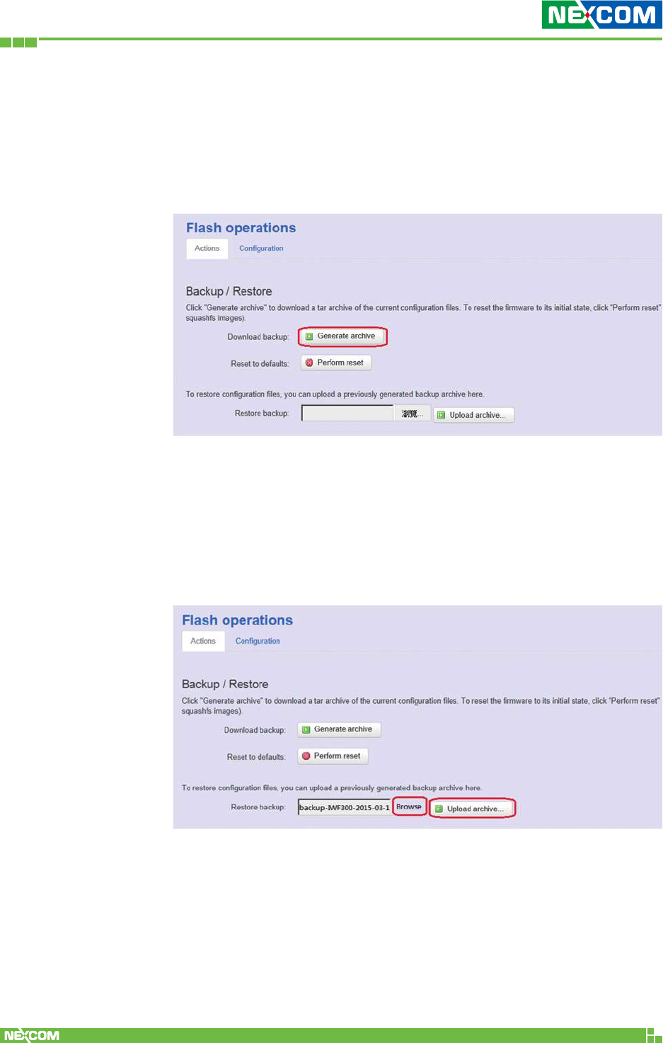
2.3.4.2 Backup Configuration
To backup your current configuration, please choose “System”
from the menu bar, then select “Backup/Flash Firmware” and click
the “Generate archive” button under the Backup / Restore section,
like:
Then save it as a file in your PC.
To restore the device to your previous configuration, please choose
“System” from the menu bar, then select “Backup/Flash Firmware”
and click “Browse” under the section to select your previous
configuration file, then click the button “Upload archive…”, like:
Note: After restoring the file, the system will apply the changes
and reboot automatically. Due to the settings from configuration
backup, the IP address may change and you have to enter the new
IP address accordingly. Otherwise, the new web page may not be
accessible.
Copyright © 2018 NEXCOM International Co., Ltd. All Rights Reserved. NIO 51 User Manual
43
Chapter 2: System Configuration
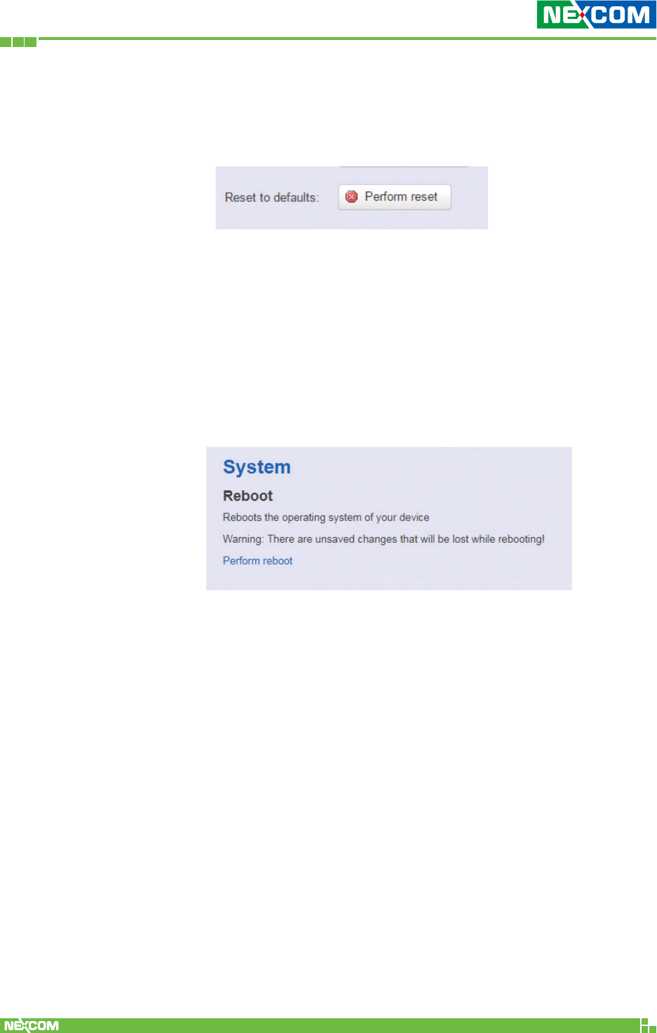
2.3.4.3 Reset to default
To reset NIO 51 to default settings, please click “Perform
reset”.
Note: The whole programming might take several minutes to
complete the process. PLEASE DO NOT REBOOT OR POWER
OFF THE DEVICE before the whole progress completes.
2.3.7 Reboot
Click the “Perform Reboot” button to warm start the system.
After the system finishes the reboot process, it will direct back
to the Login page.
Copyright © 2018 NEXCOM International Co., Ltd. All Rights Reserved. NIO 51 User Manual
44
Chapter 2: System Configuration
2.4 Network
2.4.1 Interfaces
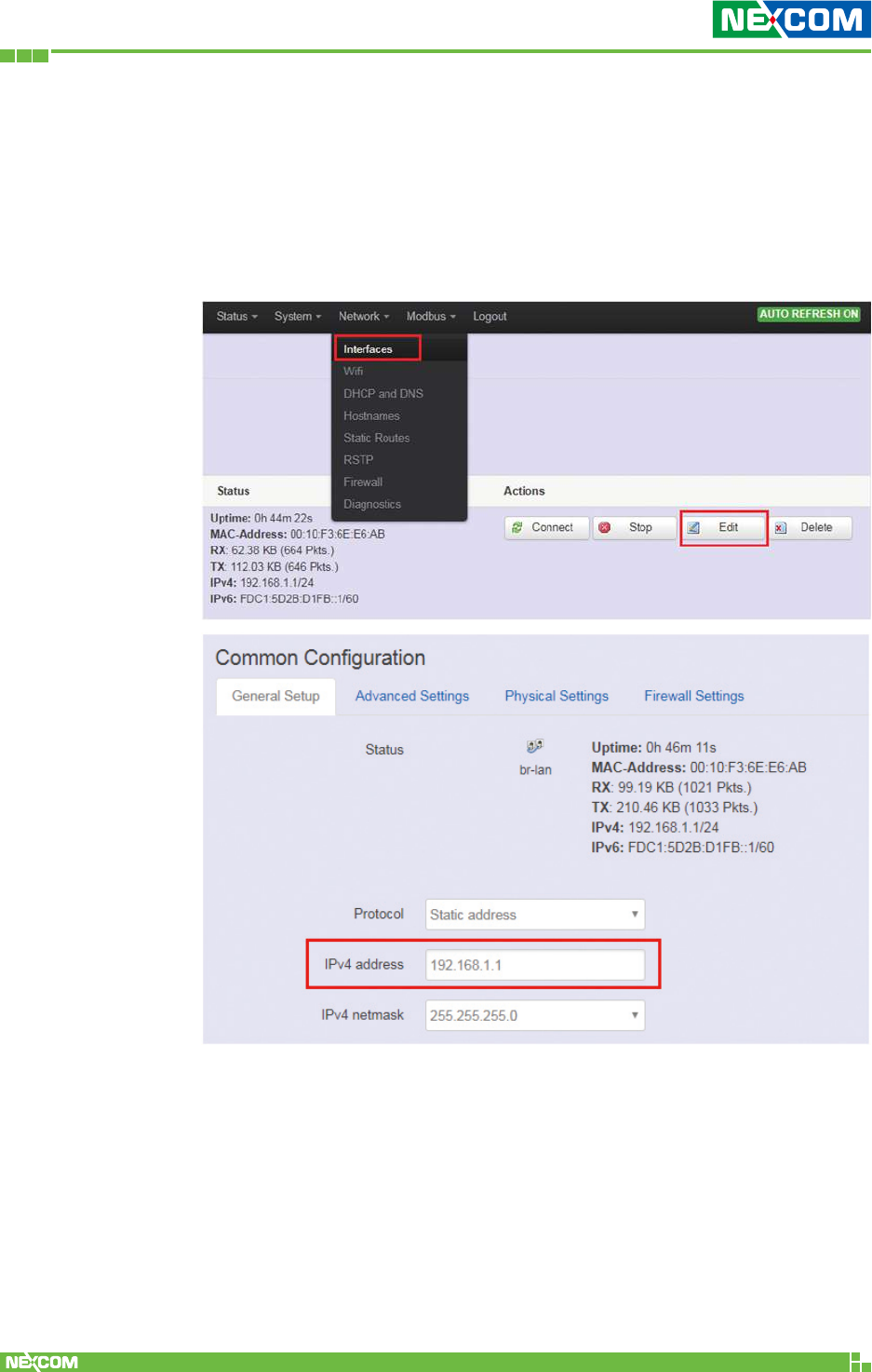
2.4.1.1 Change Default IP Address
To set up a new IP address, please click “Network” from the
menu bar, then select “Interfaces” and click “Edit”.
Under the “IPv4 address” field, you can input the new IP
address of this device, and then pull down the scroll bar to the
bottom of the Web GUI page and click “Save & Apply” to save
this new IP address into flash and apply it immediately.
Note: After applying new IP, it would take several minutes to
switch to the Status page via the new IP address. Please enter
the new IP address on the browser again if the GUI does not
switch to new GUI page after 5 minutes.
Copyright © 2018 NEXCOM International Co., Ltd. All Rights Reserved. NIO 51 User Manual
45
Chapter 2: System Configuration
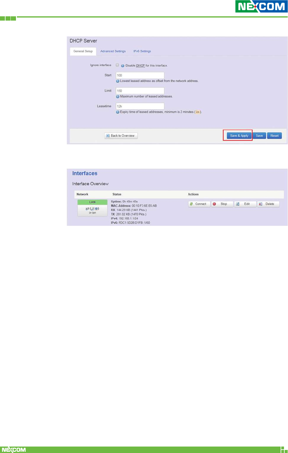
2.4.1.2 Interfaces Overview
Connect: Link this interface to the network, functions like “Save &
Apply”.
Stop: Disable the interface to link to the network.
Edit: Modify LAN port group settings.
Delete: Delete this interface group.
Copyright © 2018 NEXCOM International Co., Ltd. All Rights Reserved. NIO 51 User Manual
46
Chapter 2: System Configuration
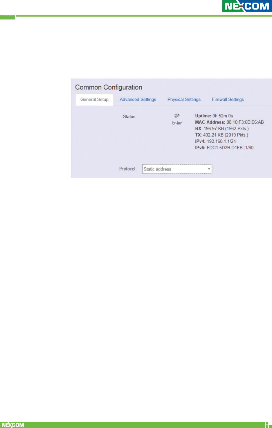
2.4.1.3 LAN Interface Overview
On this page you can configure the network interfaces. You can
bridge several interfaces by ticking the “bridge interfaces” field and
enter the names of several network interfaces separated by spaces.
<General Setup>
The default protocol is static address setting. It is suggested that a
static IP is used for the LAN port.
Static address
Static IP (Manual): Choose this option if you do not have a DHCP
server in your network, or if you wish to assign a static IP address to
NIO 51.
DHCP client
When Dynamic IP (DHCP) is selected, the DHCP client will be
functional once this selection is made.
Unmanaged
This interface has no configuration interface or options.
PPP
Used to provide point to point link for connecting NIO 51 to old
serial modem.
PPPoE
Used for cable modem or ADSL users to link NIO 51 to your
internet provider.
Copyright © 2018 NEXCOM International Co., Ltd. All Rights Reserved. NIO 51 User Manual
47
Chapter 2: System Configuration
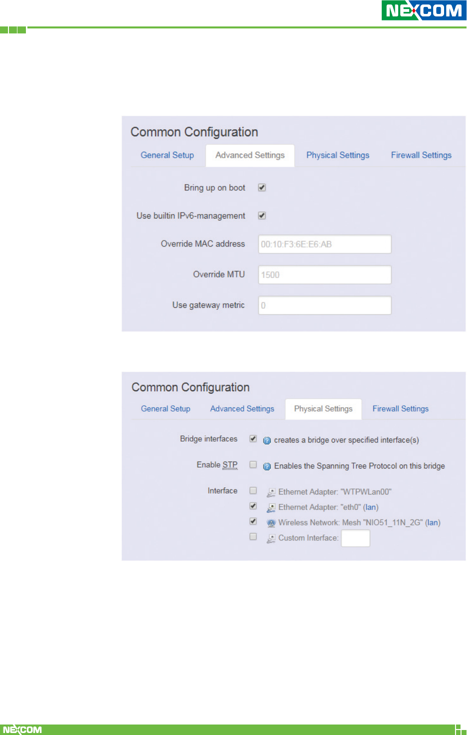
<Advanced Settings>
Advanced settings and configuration, it is advised that generic
users leave the settings unchanged.
<Physical Settings>
Bridge interfaces
You can bridge an interface group for your LAN interface. After
enabling bridge interfaces, select the interfaces to bridge.
Interface
Select the interfaces for your bridge group. Select both the
Ethernet adapter (most likely eth0.1 or eth1) and the wireless
network.
Copyright © 2018 NEXCOM International Co., Ltd. All Rights Reserved. NIO 51 User Manual
48
Chapter 2: System Configuration
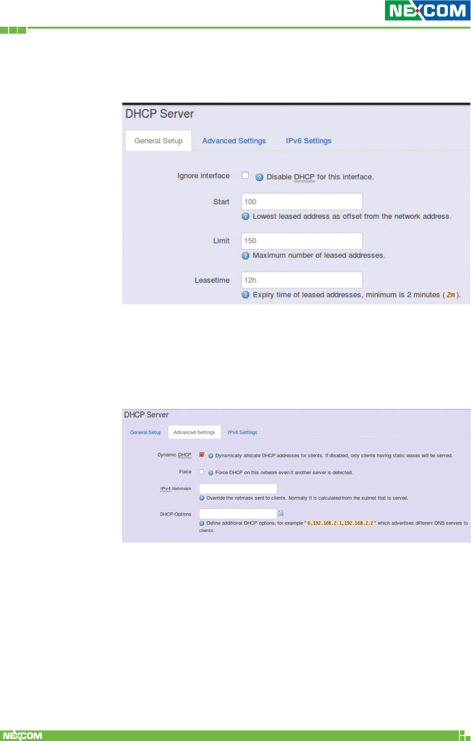
2.4.1.4 DHCP Server
<General Setup>
Ignore Interface: Select this option to disable your DHCP server,
you will need a static IP or another DHCP server for your network
interfaces. Default is “enable DHCP”.
<Advanced Settings>
Dynamic DHCP: Dynamically allocate DHCP addresses for clients. If
disabled, only clients with static leases will be served.
Force: Force DHCP on this network even if another server is
detected.
Copyright © 2018 NEXCOM International Co., Ltd. All Rights Reserved. NIO 51 User Manual
49
Chapter 2: System Configuration
2.4.2 WiFi
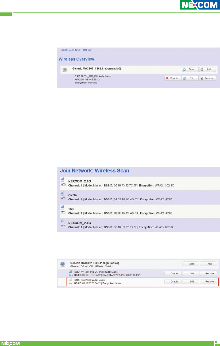
2.4.2.1 Wireless Overview
To set up the Wireless configuration, please select “Network” in
the tab, then select “WiFi”, which would show you the current
status of radio interfaces.
Wireless Overview includes channel, SSID, MAC address and
security setting information.
Scan: Scan any AP nearby the Radio, we can check how many APs
are nearby this AP and avoid using the same channel.
Add: Add a new virtual AP in the same radio interface. You will see
the new interface after clicking “Add”.
Disable: Disable the radio interface.
Edit: Configure the radio interface.
Remove: Remove radio interface. Please note that the radio must
be disabled first when you don’t want to use the radio interface.
Copyright © 2018 NEXCOM International Co., Ltd. All Rights Reserved. NIO 51 User Manual
50
Chapter 2: System Configuration
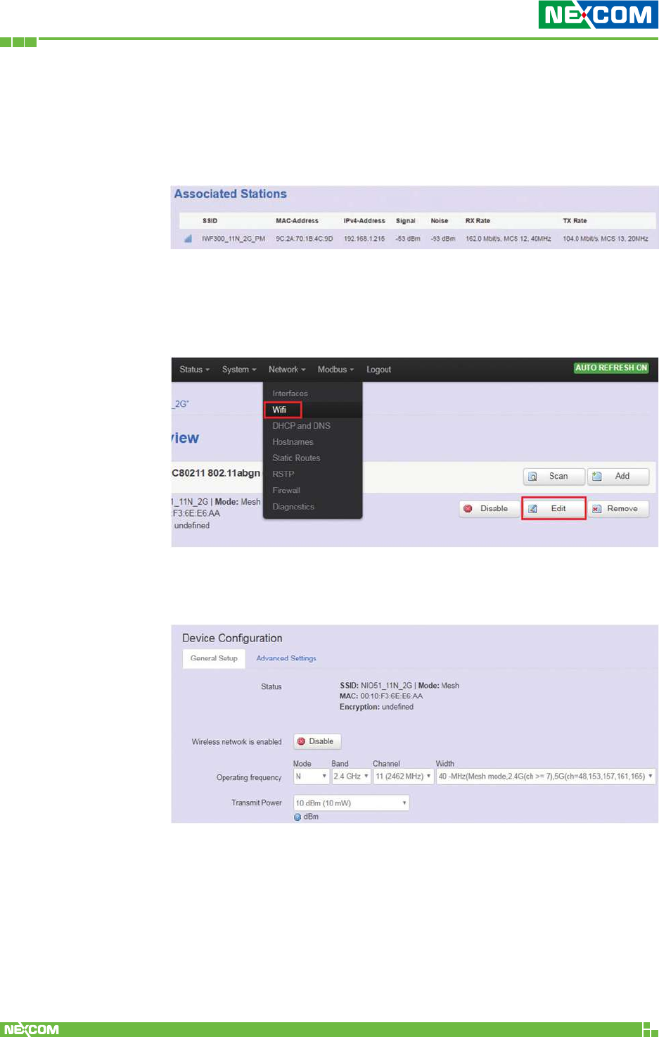
2.4.2.2 Associated Stations
Associated stations show wireless client connection information. It
includes the SSID, MAC/IP address, RSSI signal strength and Tx/Rx
rate of the wireless client connected.
2.4.2.3 Wireless Configuration
Please select “Network” -> “Wifi” and click Edit to configure
wireless settings.
The Device Configuration section covers physical settings of the
radio hardware such as channel, transmit power and so forth.
<General Setup>
Wireless network is enabled: Enable or disable the radio
interface.
Operating frequency: Select radio frequency and channel
bandwidth for signal transmission.
Copyright © 2018 NEXCOM International Co., Ltd. All Rights Reserved. NIO 51 User Manual
51
Chapter 2: System Configuration
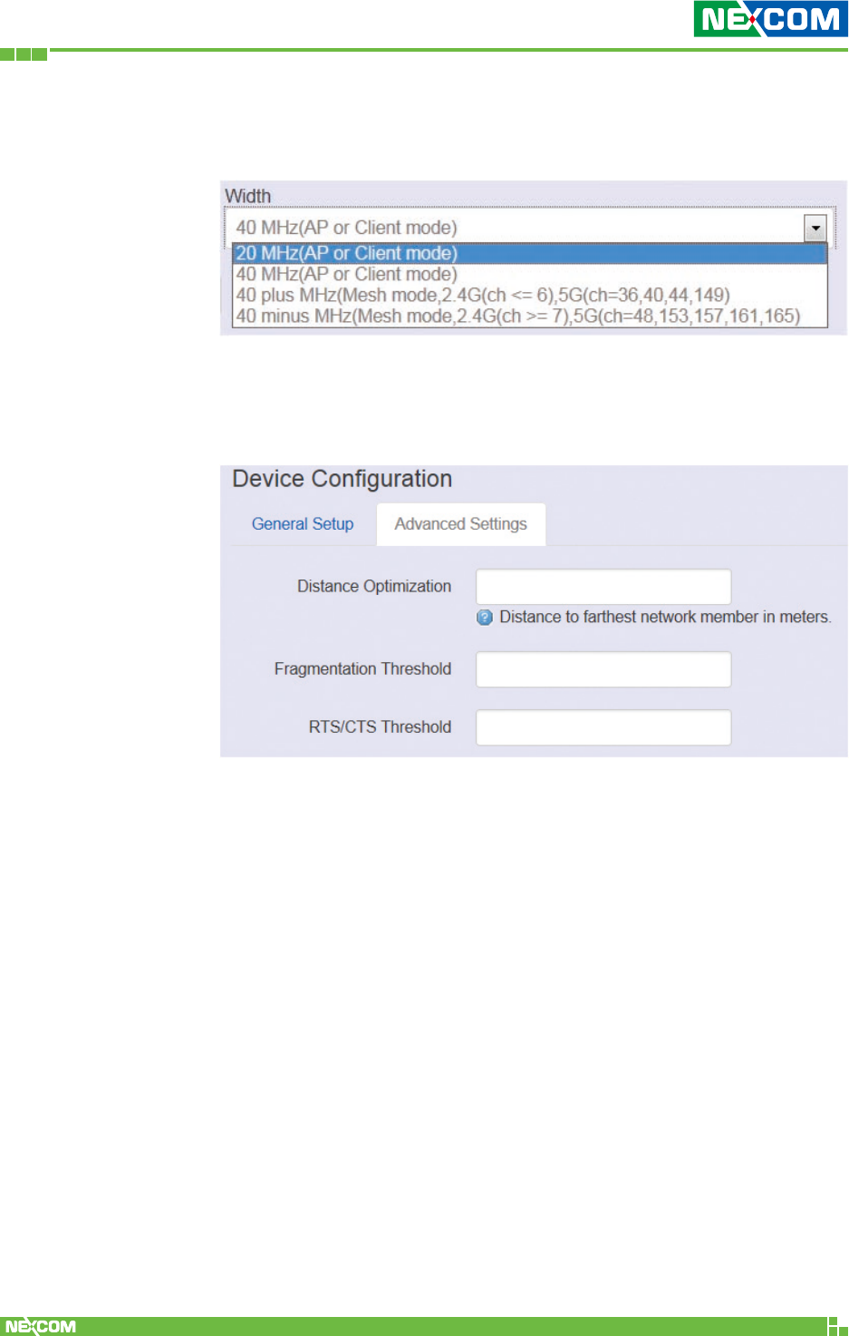
For channel bandwidth, please note you need to confirm AP/client
mode or mesh mode and the channel you will use.
Transmit Power: Select the transmit power of a radio.
<Advanced Settings>
Distance Optimization: Specify the ACK timeout by entering
the value manually. ACK timeout can be entered by defining the
link distance. A value too short for the ACK timeout may cause
transmission time out and no packets can be received. A value too
long may cause low throughput rate.
Fragmentation Threshold: Default=off. Specify the
Fragmentation threshold by entering the value manually [300-
2346 bytes]. This is the maximum size for a packet before data
is fragmented into multiple packets. Setting the Fragmentation
threshold too low may result in poor network performance. Only
minor modifications of this value are recommended.
Copyright © 2018 NEXCOM International Co., Ltd. All Rights Reserved. NIO 51 User Manual
52
Chapter 2: System Configuration
RTS/CTS Threshold: Default=off. RTS/CTS (Request to Send /
Clear to Send) is the optional mechanism used by the 802.11
wireless networking protocol to reduce frame collisions introduced
by the hidden node problem. RTS/CTS is an additional method to
implement virtual carrier sensing in Carrier sense multiple access
with collision avoidance (CSMA/CA). Specify the RTS threshold by
entering the value manually [0-2346 bytes]. Typically, sending RTS/
CTS frames does not occur unless the packet size exceeds this
threshold.
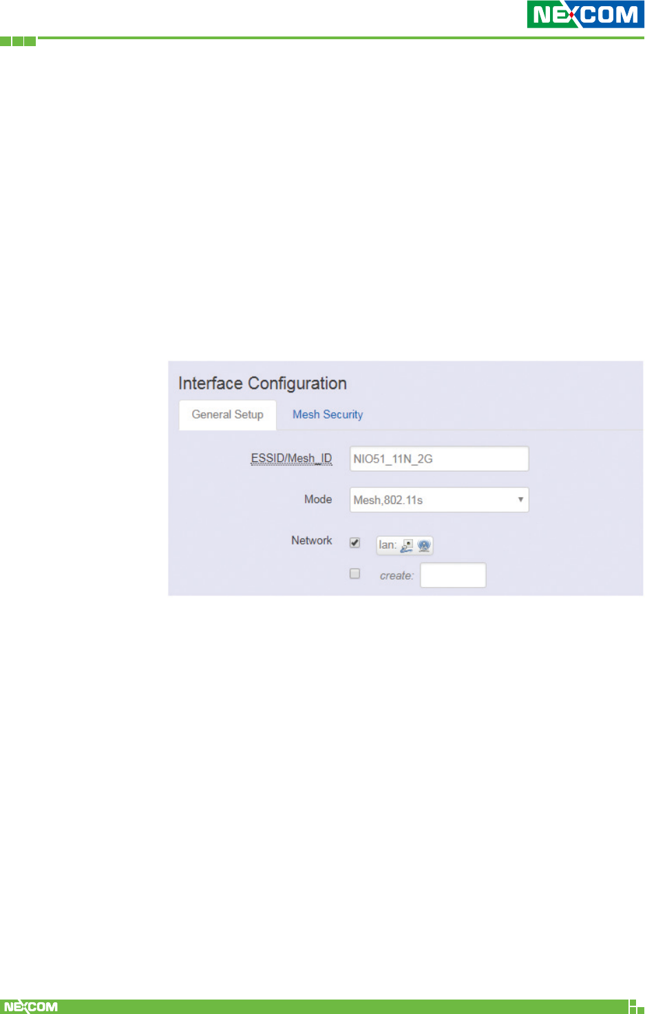
The Interface Configuration section covers SSID operation mode
and encryption.
<General Setup>
ESSID: Edit the SSID. The default SSID for radio0 is NIO51_11N and
default SSID for radio1 is NIO51_11N_2G.
Mode: Select the operation mode:
• Client Router
• 802.11s (Mesh mode)
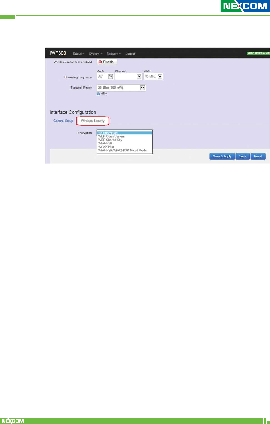
Copyright © 2018 NEXCOM International Co., Ltd. All Rights Reserved. NIO 51 User Manual
53
Chapter 2: System Configuration
<Wireless Security>
Encryption: To setup the Security on Radio, please select one of the
Encryption method:
• No Encryption
• WEP Open System: WEP provides a basic level of security, preventing
unauthorized access to the network. WEP uses static shared keys that
are manually distributed to all clients that want to use the network.
• WEP Shared Key: WEP provides a basic level of security, preventing
unauthorized access to the network, and encrypting data transmitted
between wireless clients and an access point. WEP uses static shared
keys that are manually distributed to all clients that want to use the
network.
• WPA-PSK: Clients using WPA for authentication.
• WPA2-PSK: Clients using WPA2 for authentication.
• WPA-PSK/WPA2-PSK Mixed Mode: Clients using WPA or WPA2 for
authentication.
Copyright © 2018 NEXCOM International Co., Ltd. All Rights Reserved. NIO 51 User Manual
54
Chapter 2: System Configuration
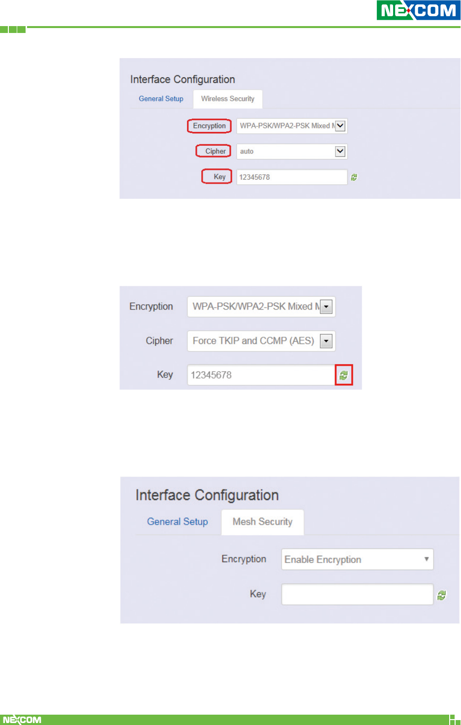
Cipher: It is recommended to select TKIP and CCMP (AES).
• Force CCMP (AES)
• Force TKIP
• Force TKIP and CCMP (AES)
The cycle icon will display the characters you just input.
For mesh security, please input the same shared key for each mesh
device.
Copyright © 2018 NEXCOM International Co., Ltd. All Rights Reserved. NIO 51 User Manual
55
Chapter 2: System Configuration
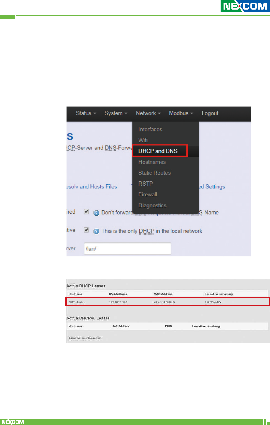
2.4.3 DHCP and DNS
A combined DHCP-Server and DNS-Forwarder for NAT firewall is
provided in NIO 51.
Click “Network” -> “DHCP and DNS” in the GUI menu. The “DHCP
and DNS” page will appear. There are four categories of settings or
lease status: “Active DHCP Leases”, “Active DHCPv6 Leases”, “Static
Leases”, and “Server Settings”.
Scroll to the following screen in the “DHCP and DNS” window.
This screen displays the lease information to which DHCP server
assigns automatically, including Hostname, IP address, MAC
address (or DUID), and Remaining Lease-time (DUID stands for the
DHCP Unique Identifier). Please look at the frame in red above.
Copyright © 2018 NEXCOM International Co., Ltd. All Rights Reserved. NIO 51 User Manual
56
Chapter 2: System Configuration
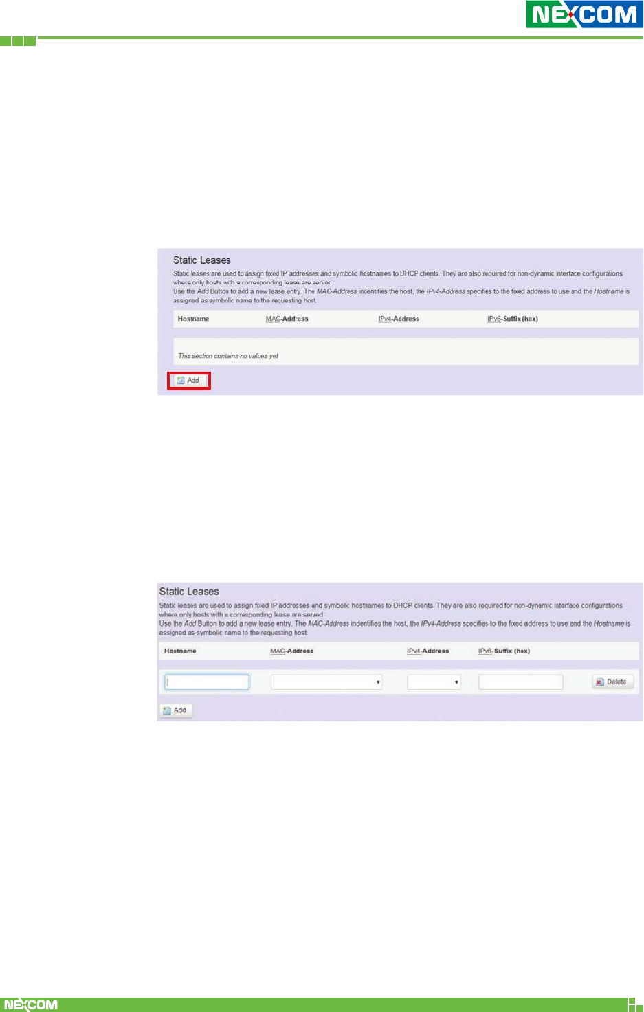
The next category that users can scroll to is “Static Leases” as
follows.
Static leases are used to assign fixed IP addresses and symbolic
hostnames to DHCP clients by calculating MAC-Address. They are
also required for non-dynamic interface configurations where only
hosts with a corresponding lease are served.
Add: Add a new lease entry.
After clicking the “Add” button, a new entry with 4 blank input
boxes will appear. Allow users to fill in the information such as the
MAC-Address (identifies the host), the IPv4-Address (specifies the
fixed address to use) and the Hostname (is assigned as symbolic
name to the requesting host).
Delete: Delete the followed entry.
Scroll to the screen identified as “Server Settings” category.
There are 4 tabs to select more options for DHCP and DNS services in
NIO 51.
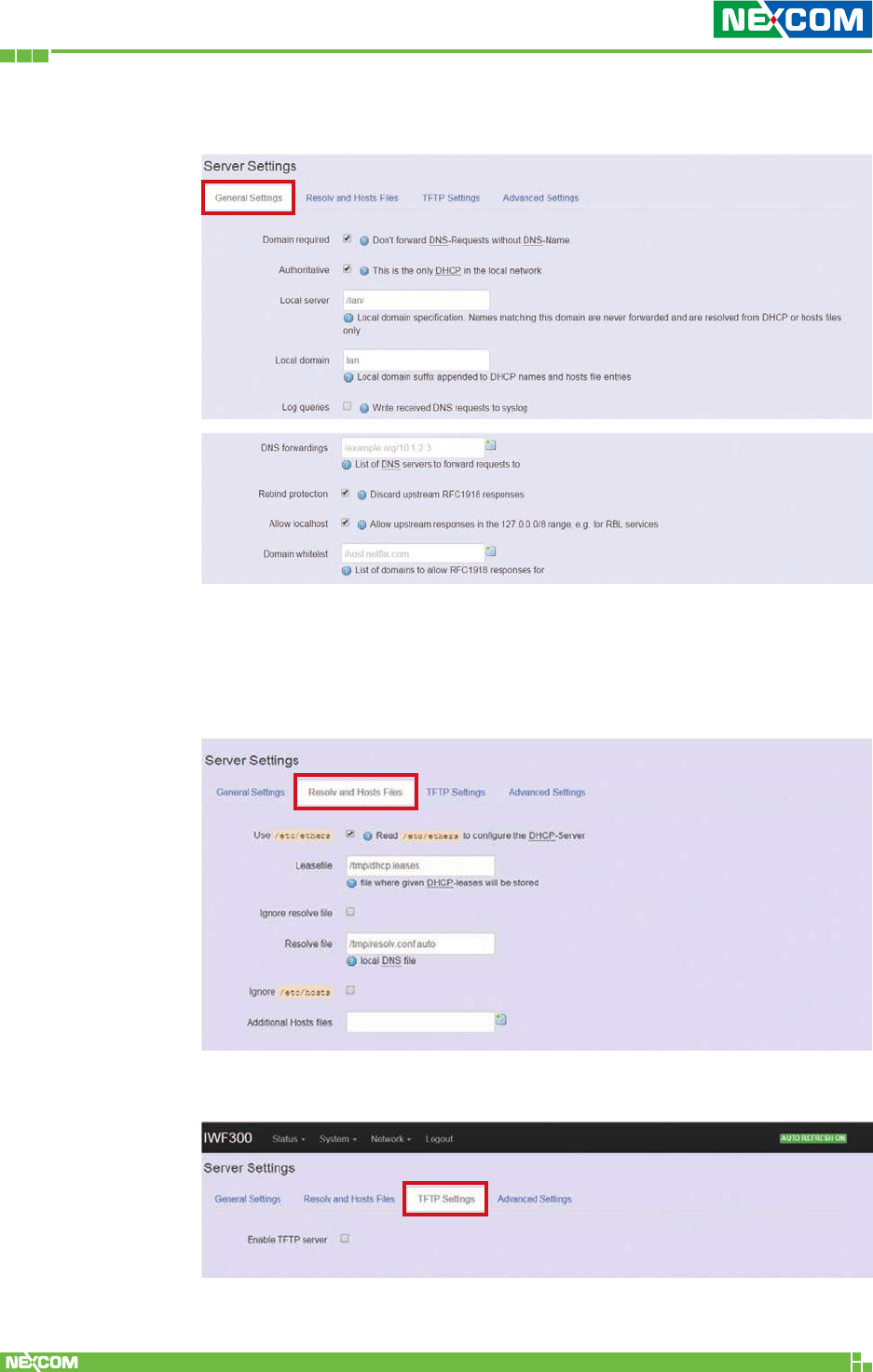
Copyright © 2018 NEXCOM International Co., Ltd. All Rights Reserved. NIO 51 User Manual
57
Chapter 2: System Configuration
<General Settings>
Domain required: Default value is checked.
Authoritative: Default value is checked.
<Resolve and Hosts Files>
<TFTP Settings>
By default, TFTP server is not enabled.
Copyright © 2018 NEXCOM International Co., Ltd. All Rights Reserved. NIO 51 User Manual
58
Chapter 2: System Configuration
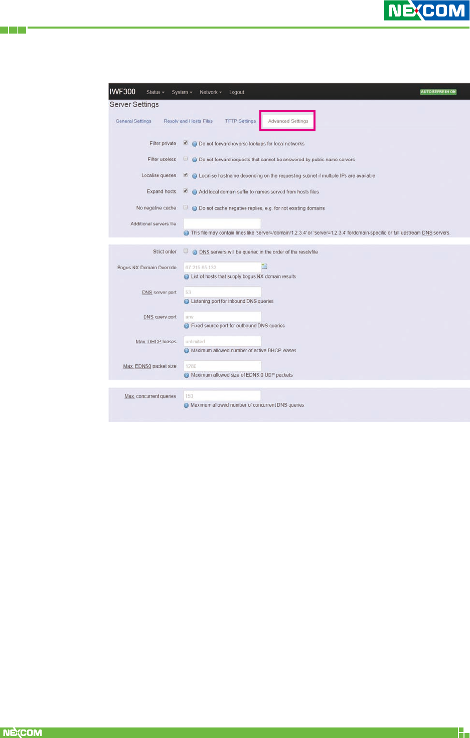
<Advanced Settings>
Max. DHCP Leases: Default value is unlimited.
Max. concurrent queries: Default value is 150.
Copyright © 2018 NEXCOM International Co., Ltd. All Rights Reserved. NIO 51 User Manual
59
Chapter 2: System Configuration
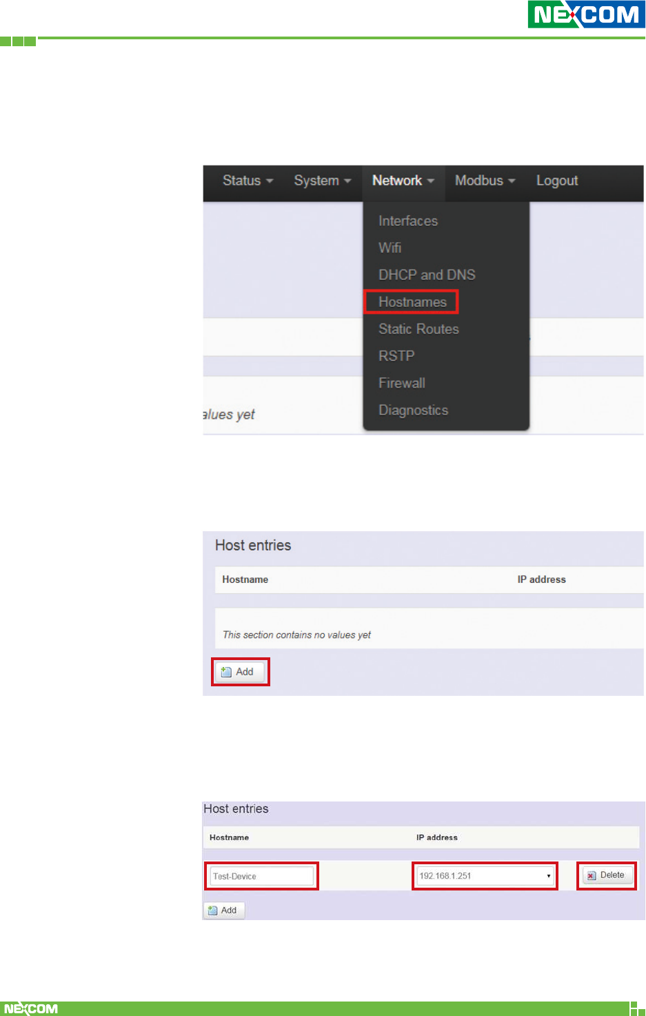
2.4.4 Hostnames
Clicking the “Network” -> “Hostnames” in the GUI menu will
bring up the “Hostnames” page.
For devices that do not have hostname or do not resolve
automatically, a hostname-IP paired to a specific device must
be assigned.
Add: Create a host entry (hostname-IP pair) for a specific device.
(For example, Hostname => “Test-Device”; IP address
=>“192.168.1.251”)
Delete: Delete the followed host entry.
Copyright © 2018 NEXCOM International Co., Ltd. All Rights Reserved. NIO 51 User Manual
60
Chapter 2: System Configuration
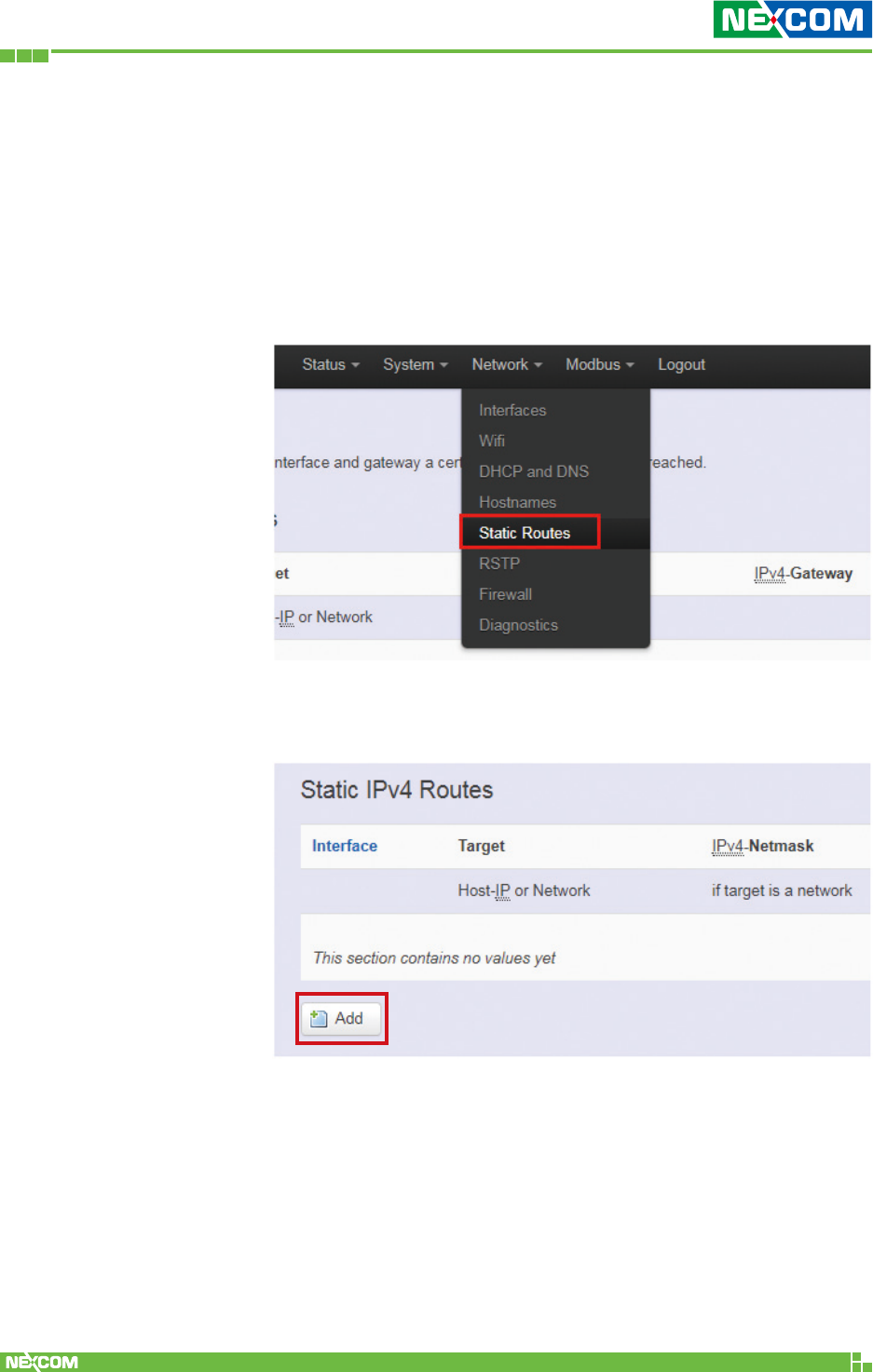
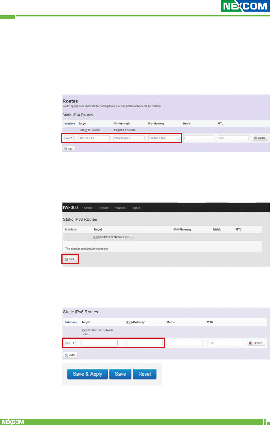
2.4.5 Static Routes
Clicking “Network” -> “Static Routes” in the GUI menu will
bring up the “Routes” page for two categories: “Static IPv4
Routes” and “Static IPv6 Routes”.
Static routes specify the interface and gateway which certain
host or network can be reached over. Such pair (interface and
gateway) is called a route.
For IPv4 network, scroll down to the “Static IPv4 Routes”
screen as follows.
Add: Add an entry for a route to an IPv4 network or host.
Copyright © 2018 NEXCOM International Co., Ltd. All Rights Reserved. NIO 51 User Manual
61
Chapter 2: System Configuration
Delete: Delete a followed route entry.
For IPv6 network, scroll down to the “Static IPv6 Routes” screen as
follows.
For example: Target network = 192.168.10.0;
Netmask = 255.255.255.0; NIO 51 WAN IP = 192.168.0.1;
The route to be assigned will be “wan” for interface and
“192.168.0.253” for gateway.
Leave “Metric” and “MTU” field to default values as 0 and 1500
respectively.
Add: Add an entry for a route to an IPv6 network or host.
Clicking the “Add” button will show the following entry.
Clicking the “Save & Apply” button will activate the entries.
Copyright © 2018 NEXCOM International Co., Ltd. All Rights Reserved. NIO 51 User Manual
62
Chapter 2: System Configuration
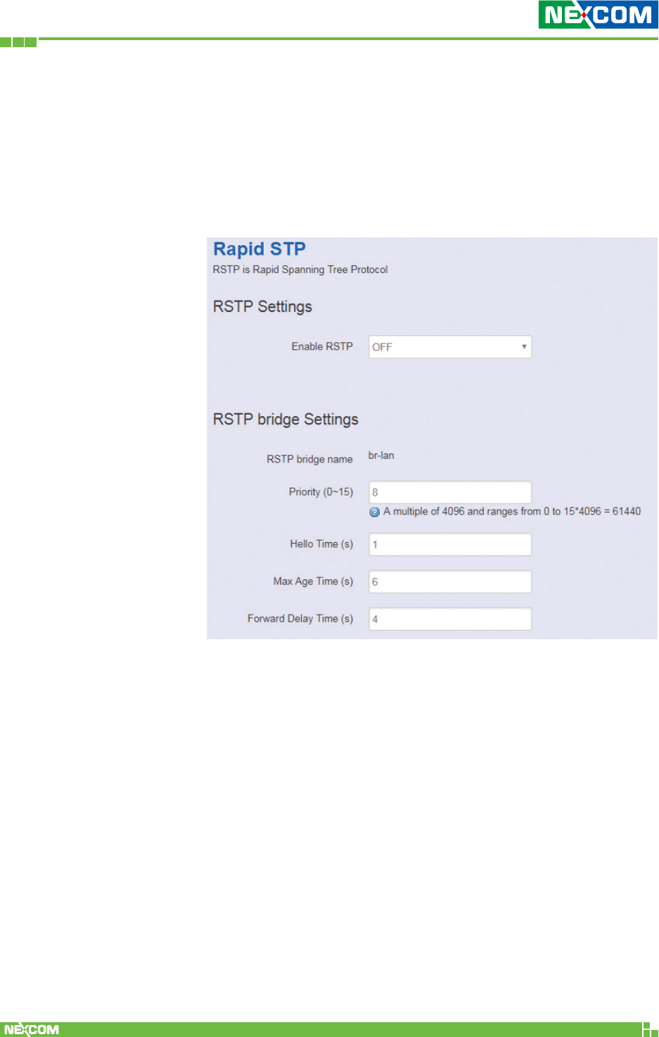
2.4.6 RSTP
Normally, when an AP LAN port connects to a LAN switch,
enabling RSTP is required. For NIO 51, RSTP is not required.
Click “Network” -> “RSTP” in the GUI menu, and navigate to
the RSTP page for configuring RSTP attributes in NIO 51.
Priority: Used to decide which switch is the root bridge. The
smaller the value; the higher the Priority. If switch has same
Priority, compare MAC address. Root bridge can decide Hello
Time, Max Age, Forwarding Delay of the entire network.
Hello Time: The hello time is the time between each bridge
protocol data unit (BPDU) that is sent on a port. This time is
equal to 1 second by default.
Max Age Time: Cannot receive BPDU in specified max age
time, system will re-establish RSTP topology. This time is 6
seconds by default.
Forward Delay Time: The forward delay is the time that is
spent in the listening and learning state. This time is equal to 4
seconds by default.
Copyright © 2018 NEXCOM International Co., Ltd. All Rights Reserved. NIO 51 User Manual
63
Chapter 2: System Configuration
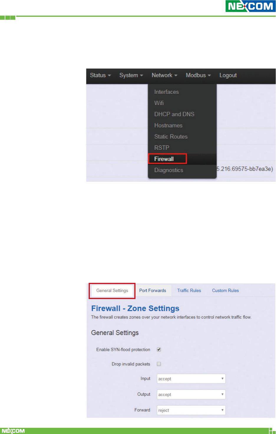
2.4.7 Firewall
Click “Network” -> “Firewall” in the GUI menu, and navigate
to the firewall attributes configuration page.
<General Settings>
Clicking the “General Settings” tab on the top of the screen
will show the “Zone Settings” configuration including
“General Settings” and “Zones” categories.
In the “General Settings” category, there are 5 basic options
for traffic control over interfaces:
”Enable SYN-flood protection” (default: enabled), “Drop
invalid packets” (default: disabled), “Input” (default: accept),
“Output” (default: accept), and “Forward” (default: reject).
Copyright © 2018 NEXCOM International Co., Ltd. All Rights Reserved. NIO 51 User Manual
64
Chapter 2: System Configuration
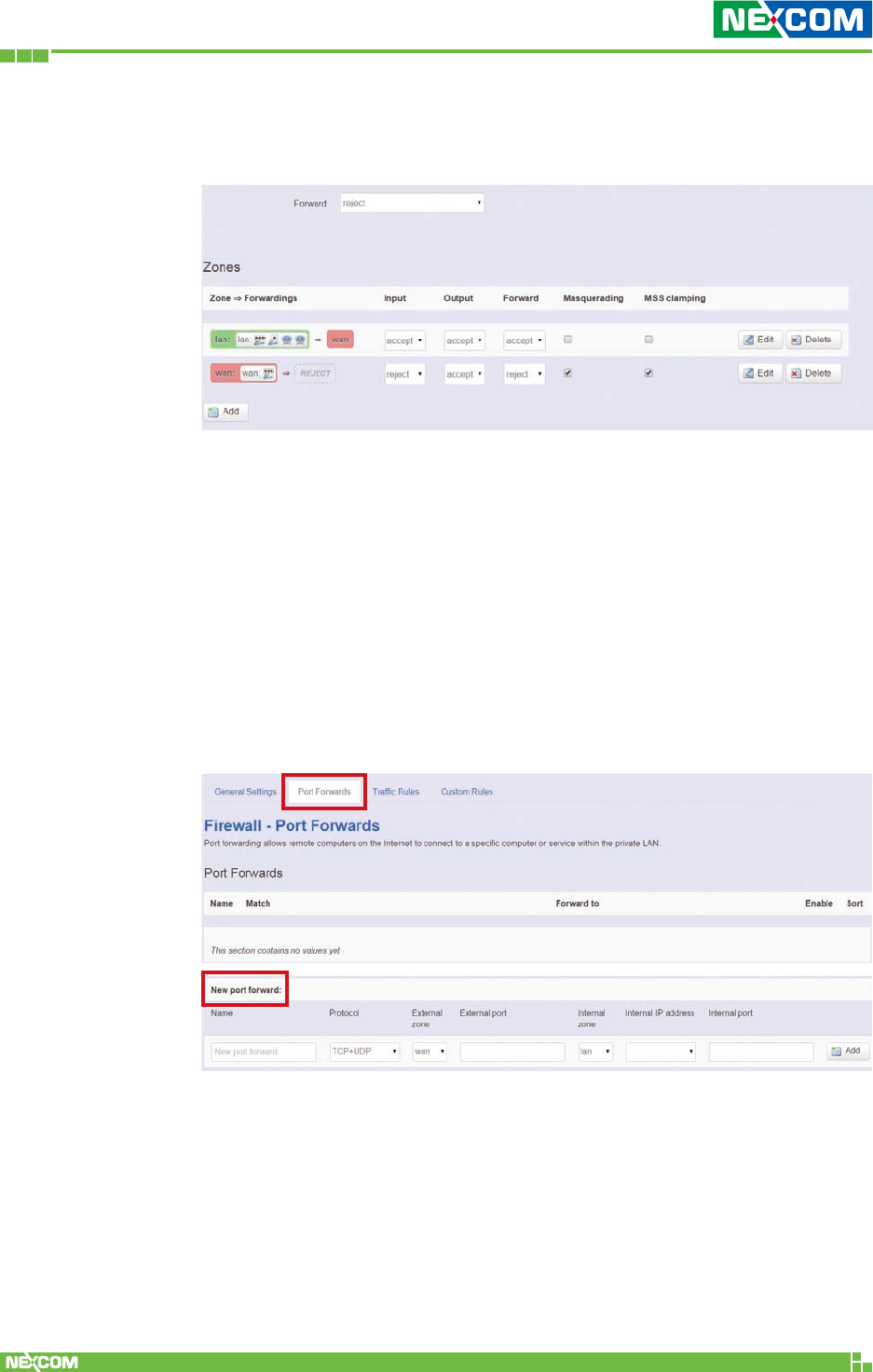
In the “Zones” category, create or edit zones over your network
interfaces to control network traffic flow.
There are 3 control buttons for “Zones” settings:
Edit: Edit the followed flow entry.
Delete: Delete the followed flow entry.
Add: Create a new entry for traffic flow among zones over interfaces.
<Port Forwards>
Clicking the “Port Forwards” tab on the top of the screen will show
the tables for port forwarding. Adding or editing a specific forwarding
table allows remote computers on the internet to connect to a
specific computer or service within the private LAN.
In the “New port forward” category, there is only one button for flow
editing:
Add: Create a new flow entry for port forwarding among zones.
Copyright © 2018 NEXCOM International Co., Ltd. All Rights Reserved. NIO 51 User Manual
65
Chapter 2: System Configuration
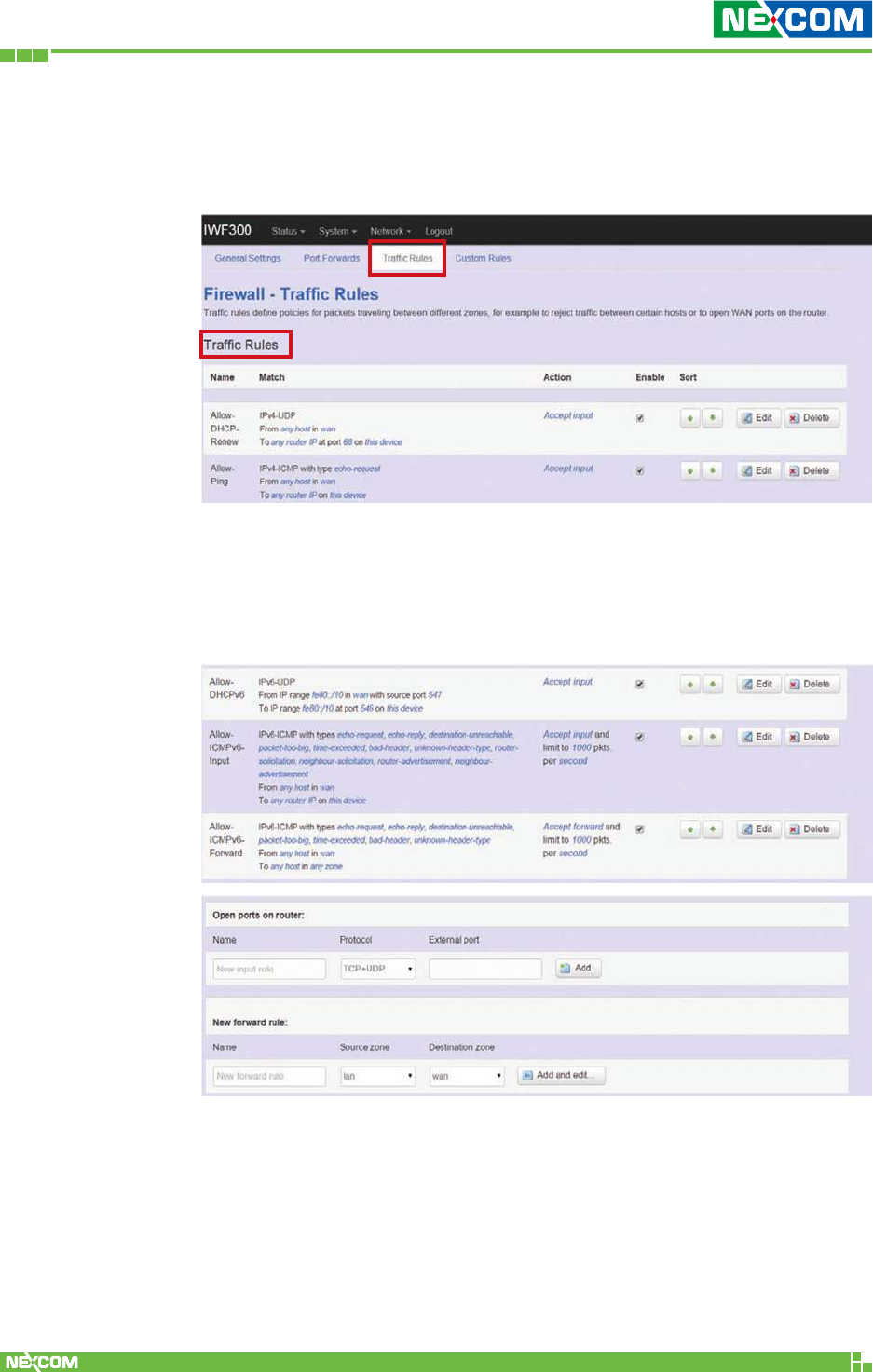
<Traffic Rules>
Clicking the “Traffic Rules” tab on the top of the screen will bring up
the policy tables of 2 categories: “Traffic Rules” and “Source NAT”.
In the “Traffic Rules” category, the flow entries of traffic rule define
policies for packets traveling between different zones (for example,
to reject traffic between certain hosts or to open WAN ports on the
router).
Copyright © 2018 NEXCOM International Co., Ltd. All Rights Reserved. NIO 51 User Manual
66
Chapter 2: System Configuration
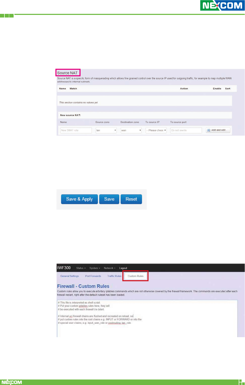
In “Source NAT” category, specific flow entries of masquerading that
allow fine grained control over the source IP used for outgoing traffic
(for example, to map multiple WAN addresses to internal subnets) can
be added or edited.
Add and edit: Create a new entry with default values, and edit at
once if required.
Please remember to click the “Save & Apply” button to activate the
new settings.
<Custom Rules>
Custom rules allow you to execute arbitrary iptables commands which
are not otherwise covered by the firewall framework. The commands
are executed after each firewall re-start, right after the default rule-set
has been loaded.
Copyright © 2018 NEXCOM International Co., Ltd. All Rights Reserved. NIO 51 User Manual
67
Chapter 2: System Configuration
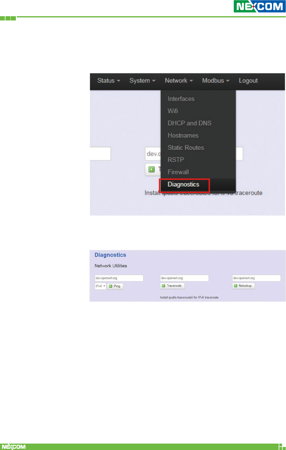
2.4.8 Diagnostics
Click “Network” -> “Diagnostics” in the GUI menu, and
navigate to the “Diagnostics” web page.
In this page, there are 3 utilities for users to diagnose interface
settings and network paths: Ping, Traceroute, and Nslookup.
Ping: Test the reachability of a host on an Internet Protocol
(IP) network and measure the round-trip time for messages
sent from the originating host to a destination host and back.
The only required parameter is the name or IP address of the
destination host.
Traceroute: Track the route packets taken from an IP network
on their way to a given destination host. The only required
parameter is the name or IP address of the destination host.
Nslookup: Query the Domain Name System (DNS) to obtain
domain name or IP address mapping.

Copyright © 2018 NEXCOM International Co., Ltd. All Rights Reserved. NIO 51 User Manual
68
Chapter 2: System Configuration
2.5 Modbus
Configuration for serial and Modbus/RTU settings. For serial to
Ethernet or wireless data transmission, NIO 51 supports TCP server or
TCP client mode to connect control server.
2.5.1 Gateway
Please select “Modbus” -> “Gateway” to configure serial and
Modbus/RTU.
<Serial and Modbus/RTU Setting>
UART mode: Select RS-232 or RS-422 or RS-485.
Model: Select “None” for RS-232/RS-422/RS-485 and select
“RTU” for Modbus/RTU.
Baudrate: 300 bps to 961200 bps.
Copyright © 2018 NEXCOM International Co., Ltd. All Rights Reserved. NIO 51 User Manual
69
Chapter 2: System Configuration
Parity: None, Odd, Even.
Databit: Data bits 8.
Stopbit: Stop bits 1
Flow Ctl: None, RTS/CTS, XON/XOFF
Timeout: This field specifies how long NIO 51 will wait for a
response before ignoring the Modbus/RTU request.
• 0: Auto
• 1 ~ 65535 milliseconds: If the serial device does not
respond within the specified time, NIO 51 will ignore the
Modbus/RTU request.
Terminator: You may need to add termination resistors in
some critical RS-485 environments to prevent the reflection of
serial signals. NIO 51 built-in 120 Ω and termination resistor
can be enabled.
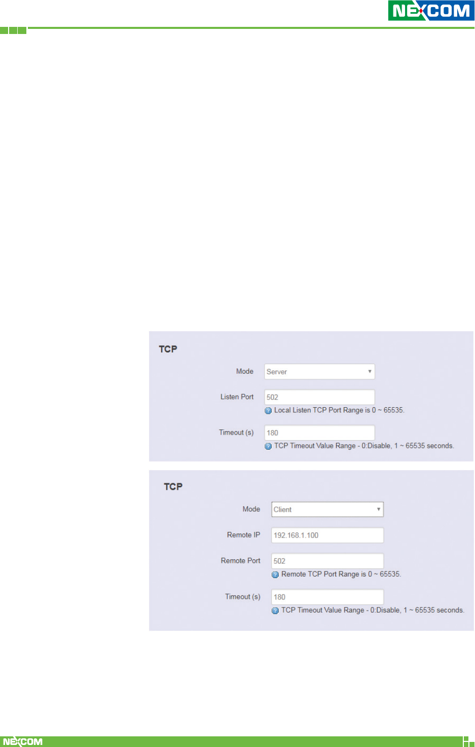
<TCP and Modbus/TCP Setting>
Mode: Select TCP client or TCP server mode.
Listen Port: Configure listen port for TCP server mode.
Remote IP: This field specifies the remote host that will access
the device.
Copyright © 2018 NEXCOM International Co., Ltd. All Rights Reserved. NIO 51 User Manual
70
Chapter 2: System Configuration
Remote Port: This field specifies the remote host TCP port
that will access the device.
Timeout: This field specifies how long NIO 51 will wait for a
response before closing the TCP connection.
• 0: Disable. The TCP connection will remain open even if
there is no response packet.
• 1 ~ 65535: If the remote host does not respond to the
packet within the specified time, NIO 51 will close the
existing TCP connection.
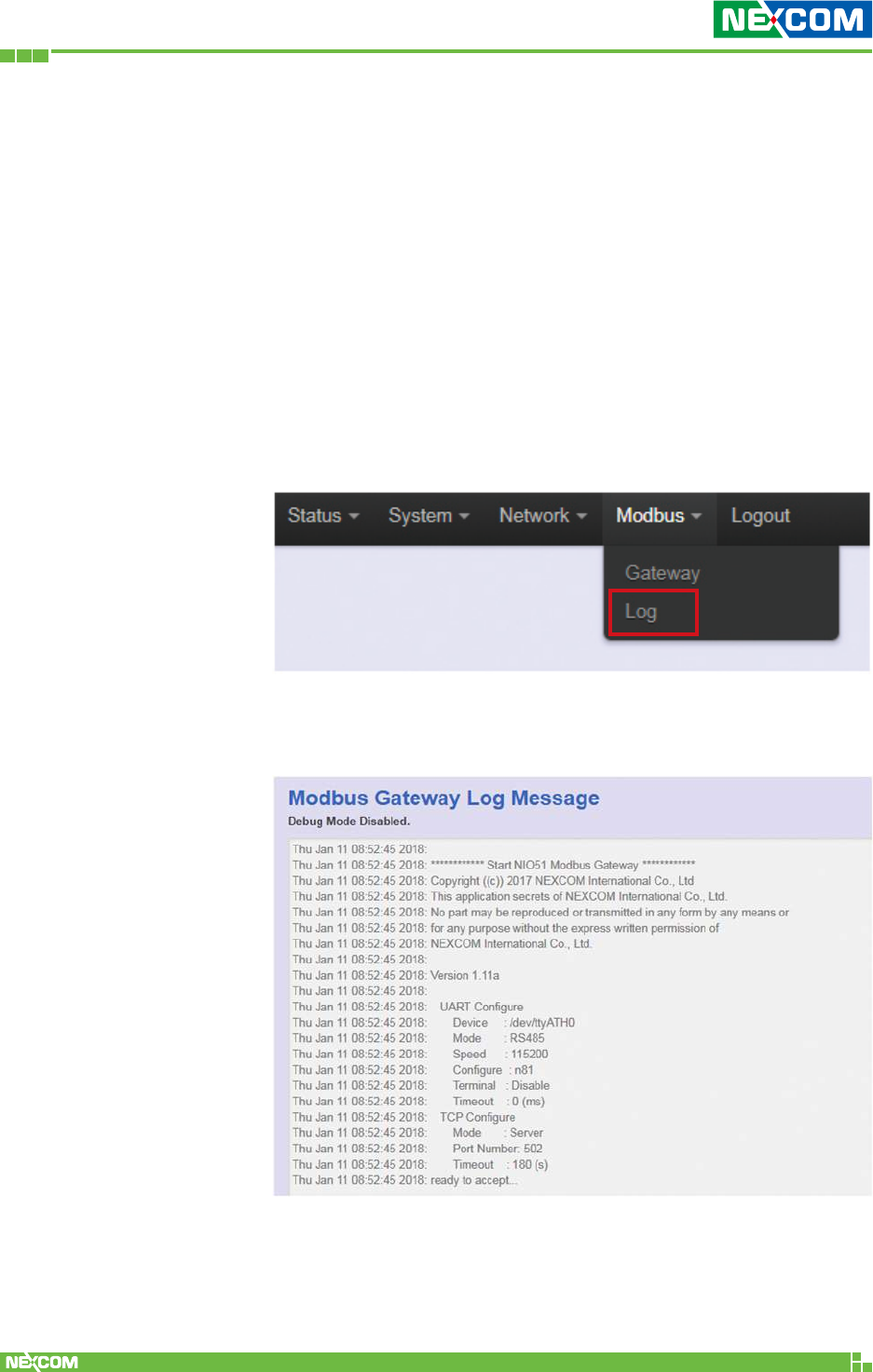
2.5.2 Log
Please select “Modbus” -> “Log” to check the log.
The logs include Serial/Modbus configuration changes, sending
and receiving of serial data and TCP connection.

Copyright © 2018 NEXCOM International Co., Ltd. All Rights Reserved. NIO 51 User Manual
71
Chapter 3: Product Specification
ChaPter 3: ProduCt sPeCifiCation
Wi-Fi Radio
• IEEE 802.11a/b/g/n, 2x2 MIMO
Serial Interface
• RS232/422/485 with isolation
– Data bits: 8
– Stop bits: 1
– Parity: none, even, odd
– Baud rate: 300bps ~ 921.6Kbps
Ethernet Interface
• 10/100Mbps
Power Requirements
• Input voltage: 12~48VDC, 2-pin removable terminal block
• Input current: 1.5A@12VDC
LED Indicator
• 1 x Power/status
• 1 x Serial status
• 3 x RSSI indicator
• 1 x Wi-Fi 2.4/5GHz indicator
• 1 x Link/Act indicator
• 1 x Extension module
Factory Default/Reset Button
• Press reset button 10 seconds for factory default
Connector Type
• DC input: Phoenix contact terminal block
• Ethernet: RJ-45 connector
• Serial signal: DB9
Wi-Fi Operating Mode
• EZ Mesh
• Client router

Copyright © 2018 NEXCOM International Co., Ltd. All Rights Reserved. NIO 51 User Manual
72
Chapter 3: Product Specification
Wi-Fi Security (Client Mode)
• WEP (64/128)
• WPA/WPA2 mixed
• WPA2-personal (PSK+CCMP/AES), WPA2-enterprise
Protocol
• Modbus TCP
• Modbus RTU
• Transparent mode for serial to Wi-Fi/Ethernet
Serial Port Characteristics
• Flow control: XON/XOFF, RTS/CTS
• Serial data log: 64KB
• Offline port buffering: 20MB
• Min. concurrent TCP client number: 10
Software Watchdog
Dimension
• 81.4 x 122.6 x 35 (W x D x H) (mm)
Weight: 450g
Mounting
• Wall mounting
• DIN mounting
Construction
• SGCC chassis with fanless design
Certification
• EMI: FCC, CE Class A
• RF
– FCC: Part 15C
– CE: EN300328, EN301893
• EN 62368-1 (pending)
• EMC
– EN301 489-1/17, FCC Part 15 subpart B, EN55032/55024
– IEC61000-4-2: level 4
– IEC61000-4-4: level 4
– IEC61000-4-5 Surge: level 3

Copyright © 2018 NEXCOM International Co., Ltd. All Rights Reserved. NIO 51 User Manual
73
Chapter 3: Product Specification
Environment
• Operating temp: -40°C ~ 70°C
• Storage temp: -40°C ~ 85°C
• Relative humidity: operating 5% ~ 95%, non-condensing
• RoHS compliant
• Vibration
– Random: 2Grms @ 5~500Hz, IEC60068-2-64
– Sinusoidal: 2Grms @ 5~500Hz, IEC60068-2-6
• Shock: 50G, half sine, 11ms, IEC60068-27
Copyright © 2018 NEXCOM International Co., Ltd. All Rights Reserved. NIO 51 User Manual
74
Chapter 4: Configuration Example
ChaPter 4: Configuration examPle
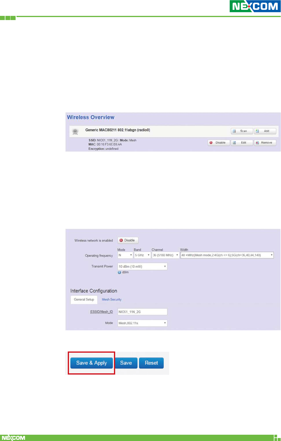
4.1 How to Configure 5G Mesh
Step 1. In the “Network” -> “Wifi” page, press the “Edit” button.
Step 2. Select the 5G channel. Mode = Mesh 802.11s
Step 3. If your 5G channel is 36, 40, 44, 149, select the 40MHz (Only
for mesh mode… ch=36, 40, 44, 149) option.
If your 5G channel is 48, 153, 157, 161, 165, select the
40MHz (Only for mesh mode… ch=48, 153, 157, 161, 169)
option.
Step 4. Press the “Save & Apply” button.
Copyright © 2018 NEXCOM International Co., Ltd. All Rights Reserved. NIO 51 User Manual
75
Chapter 4: Configuration Example
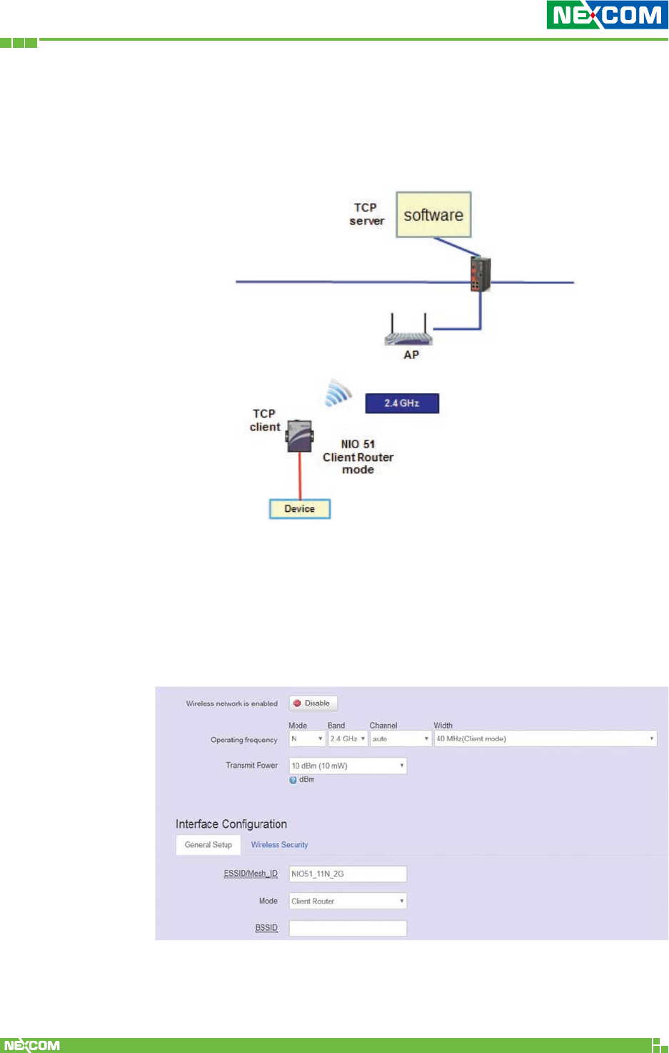
4.2 How to Configure 2.4G Client Router
Network Infrastructure Example
Step 1. Please select “Network” -> “Wifi” and click Edit.
Step 2. Configure Channel SSID and “Client router” mode.
For channel setting, you can select “auto” to scan the channel
automatically or you can select the channel if you already
know the AP channel that you want to connect.
Copyright © 2018 NEXCOM International Co., Ltd. All Rights Reserved. NIO 51 User Manual
76
Chapter 4: Configuration Example
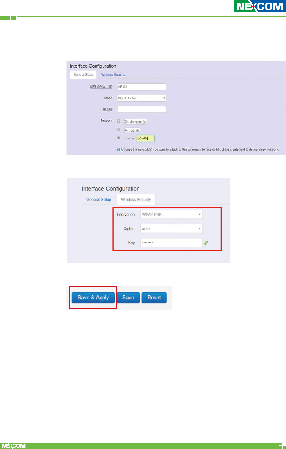
Step 3. For Network, click “create” and enter WWAN (Wireless WAN)
in the text field, then add new network interface.
Step 4. Configure the WPA2 password.
Step 5. Press the “Save & Apply” button.
Copyright © 2018 NEXCOM International Co., Ltd. All Rights Reserved. NIO 51 User Manual
77
Chapter 4: Configuration Example
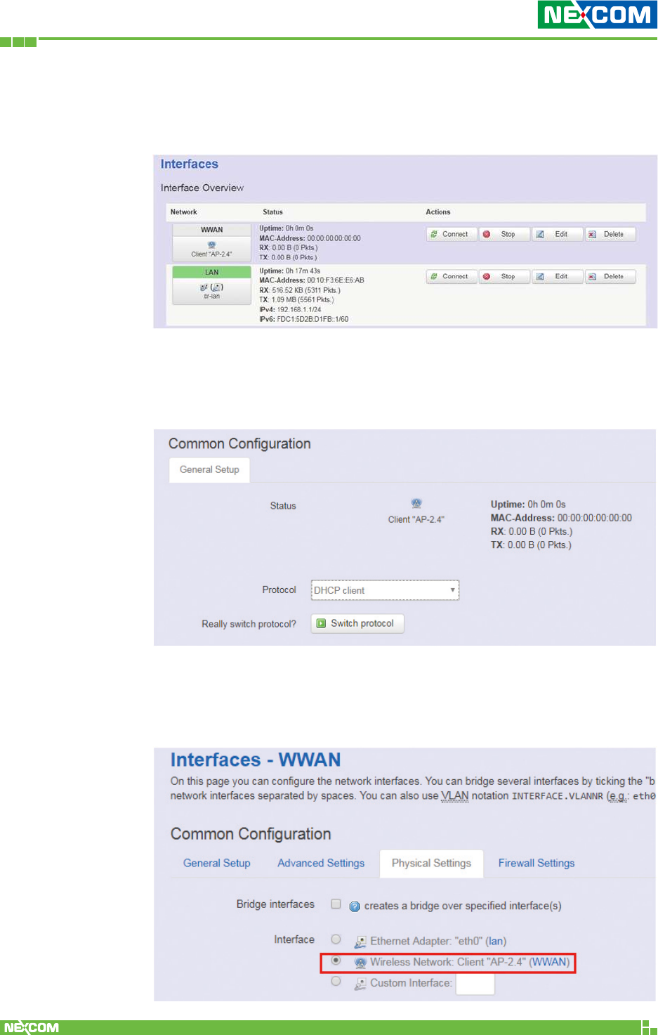
4.3 Configure WWAN Interface Setting
Step 1. Please select “Network” -> “Interface” and click WWAN Edit.
Step 2. It is suggested that DHCP client is selected if your AP has
DHCP server function. Click “Switch protocol” to switch the
DHCP client mode for WWAN interface.
Step 3. Because WWAN interface is used for AP connection, please
make sure that Wireless Network is selected in the “Physical
Settings” tab.
Copyright © 2018 NEXCOM International Co., Ltd. All Rights Reserved. NIO 51 User Manual
78
Chapter 4: Configuration Example
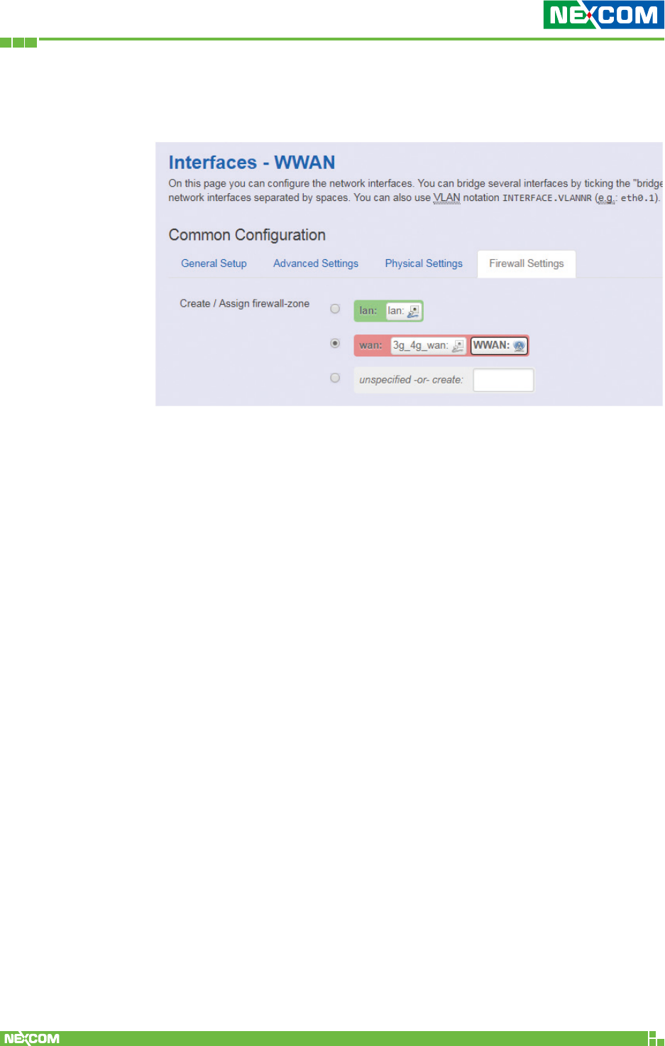
Step 4. You can enable firewall for the WWAN interface or select
“unspecified” to disable firewall.
Copyright © 2018 NEXCOM International Co., Ltd. All Rights Reserved. NIO 51 User Manual
79
Chapter 4: Configuration Example
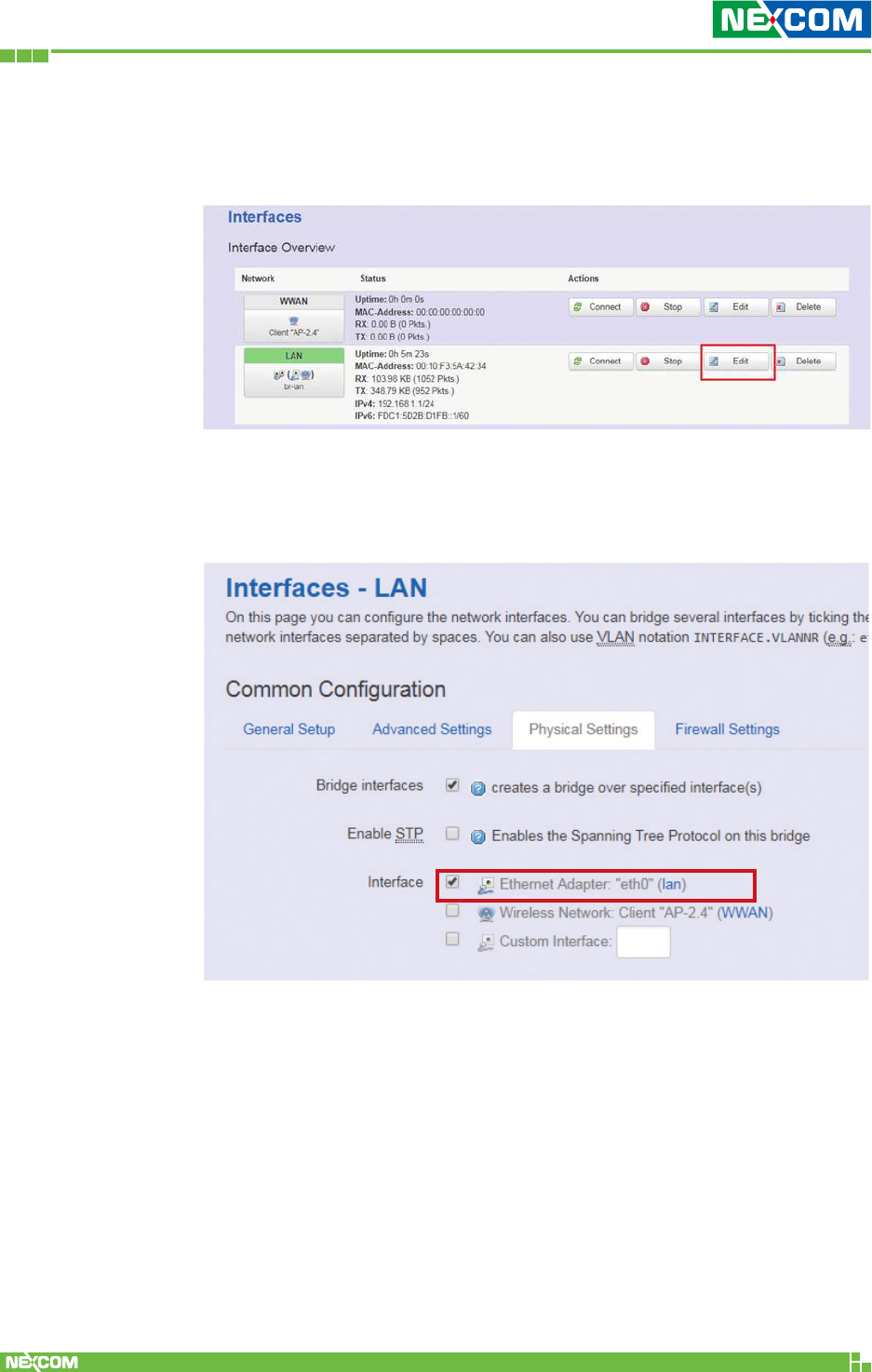
4.4 Configure LAN Interface Setting
Step 1. Please select “Network” -> “Interface” and click LAN Edit.
Step 2. Because LAN interface is used for device LAN connection,
please make sure that Ethernet Adapter is selected in the
“Physical Settings” tab.
Copyright © 2018 NEXCOM International Co., Ltd. All Rights Reserved. NIO 51 User Manual
80
Chapter 4: Configuration Example
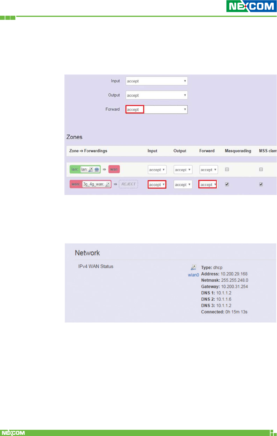
4.5 Configure Firewall Setting
Step 1. Please select “Network” -> “Firewall” and select “accept” to
accept input and forward packets.
4.6 Verify Network Status
Step 1. Please select “Network” -> “Overview” to check the WAN
status.
Copyright © 2018 NEXCOM International Co., Ltd. All Rights Reserved. NIO 51 User Manual
81
Chapter 4: Configuration Example
4.7 How to Run Firmware Upgrade
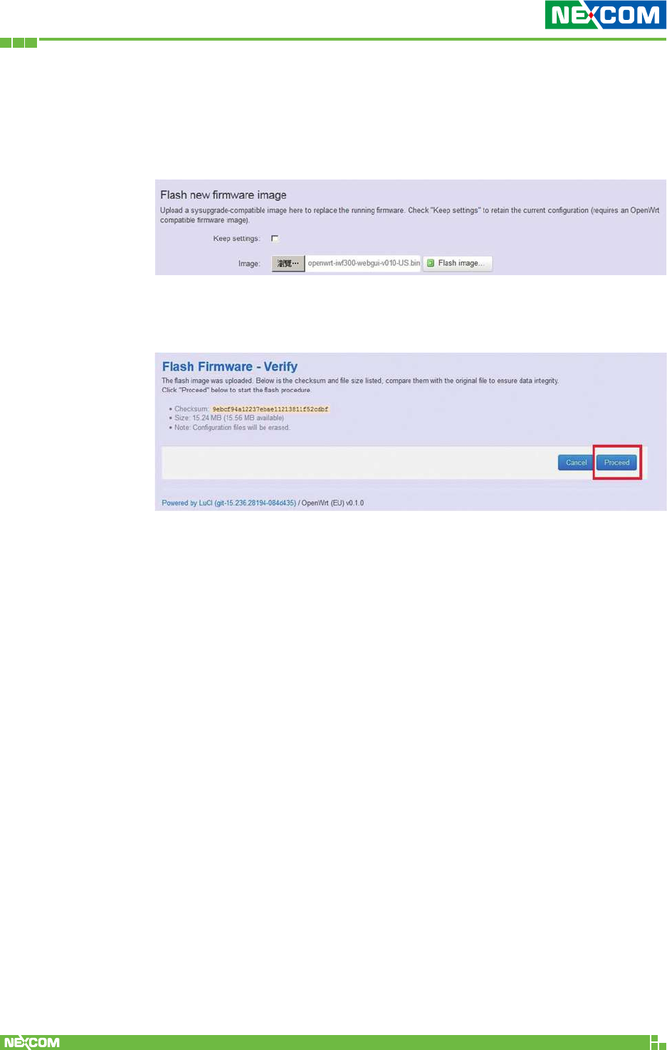
Step 1. In the “System” -> “Flash firmware” page, select your image
and press the “Flash image” button.
Step 2. Press the “Proceed” button, then the image will be flashed to
the device, please wait for 2 minutes.
Copyright © 2018 NEXCOM International Co., Ltd. All Rights Reserved. NIO 51 User Manual
82
Chapter 4: Configuration Example
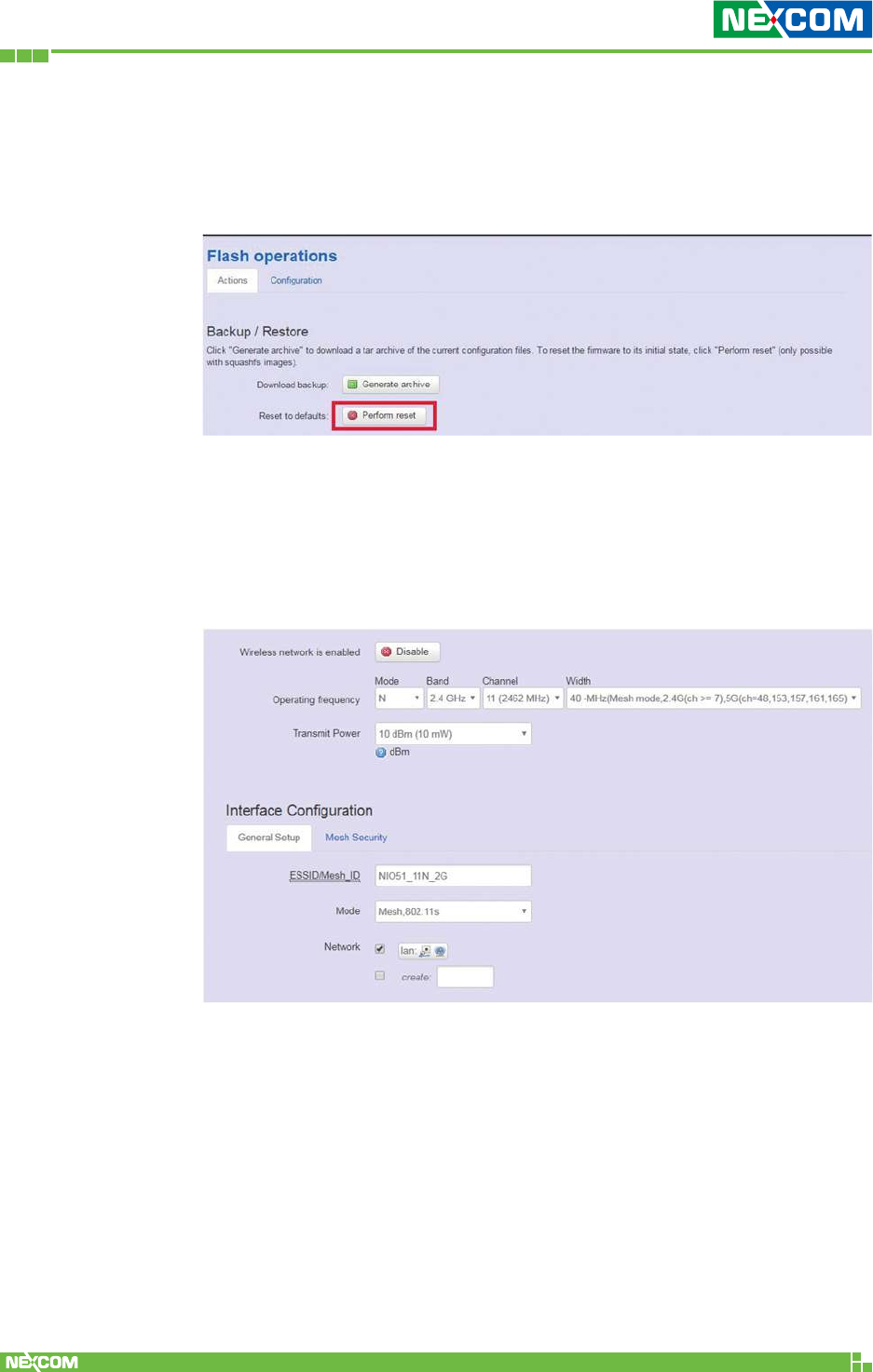
4.8 How to Restore to Default Settings
Step 1. In the “System” -> “Flash firmware” page, press the
“Platform reset” button.
NIO 51 Default Parameters:
LAN port default IP = 192.168.1.1
WAN port default IP = DHCP Client
Login user name: root
Login password: admin
Copyright © 2018 NEXCOM International Co., Ltd. All Rights Reserved. NIO 51 User Manual
83
Chapter 5: Appendix
ChaPter 5: aPPendix
5.1 Wi-Fi and 3G/4G Redundant Function
NIO 51 supports Wi-Fi and 4G redundant function. The main
application area for this function is in industrial vehicles. Industrial
vehicles use Wi-F or 4G when arriving to or leaving from stations. The
3G/4G function is a project based function.
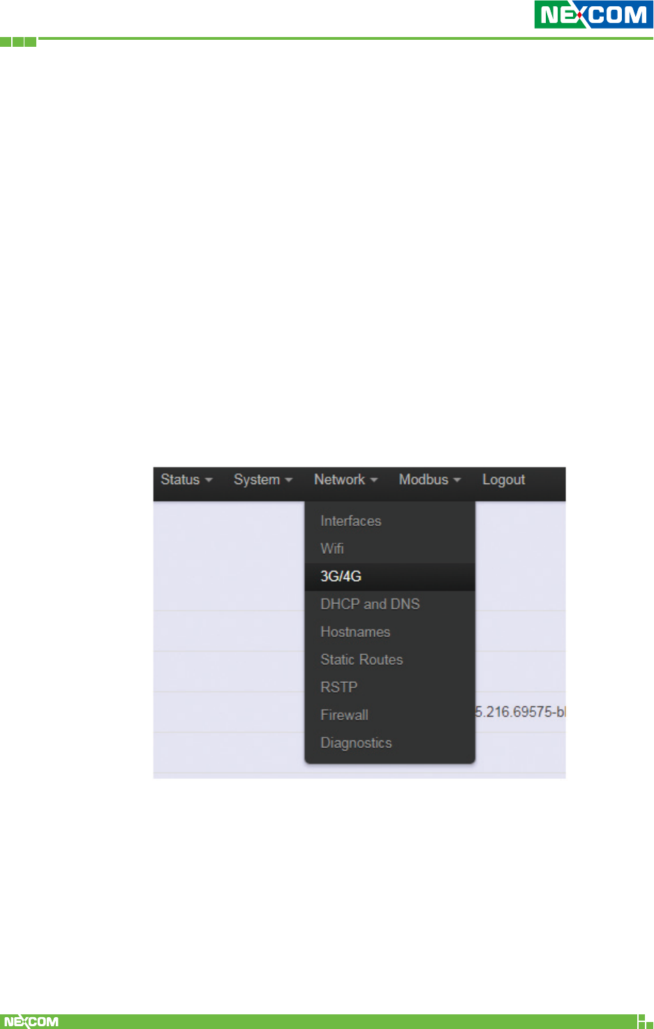
The standard NIO 51 does not include a 3G/4G module, please install
the 3G/4G module in the mini PCI slot of NIO 51 and then install an
antenna and SIM card. After finishing the installation, the 3G/4G
setting will show up in the Web GUI. Please select “Network” ->
“3G/4G” to configure.
Copyright © 2018 NEXCOM International Co., Ltd. All Rights Reserved. NIO 51 User Manual
84
Chapter 5: Appendix
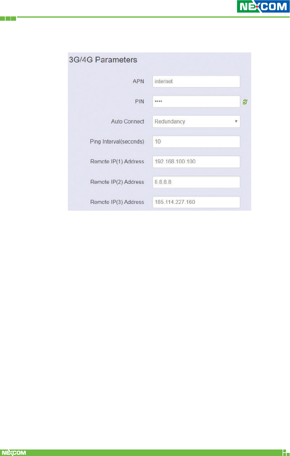
3G/4G Parameters
Please select “Redundancy” to enable Wi-Fi and 4G redundant
function. You will then need to enter Remote IP address.
When NIO 51 cannot ping Remote IP(1), NIO 51 will ping Remote
IP(2) and then Remote IP(3). If you only configured remote IP(1), NIO
51 will activate 3G/4G connection directly.
When NIO 51 can ping Remote IP(1) to Remote IP(3), NIO 51 will stop
3G/4G connection .
Remote IP(2) and Remote IP(3) settings are not required.
APN: The service provider may use access point network (APN)
information to connect 3G/4G service. Please enter the access point
network (APN) information here.
PIN: SIM card PIN code.
Auto Connect:
• None: Never connect 3G/4G.
• Yes: Always connect 3G/4G, it is suggested that Wi-Fi is disabled.
• Redundancy: Enable Wi-Fi and 4G redundant function.
Copyright © 2018 NEXCOM International Co., Ltd. All Rights Reserved. NIO 51 User Manual
85
Chapter 5: Appendix
Ping interval: Ping interval between two Remote IPs.
Remote IP(1) address: When Redundancy function is enabled, you
can configure wireless remote IP(1).
Remote IP(2) address: When Redundancy function is enabled, you
can configure wireless remote IP (2).
Remote IP(3) address: When Redundancy function is enabled, you
can configure wireless remote IP (3).
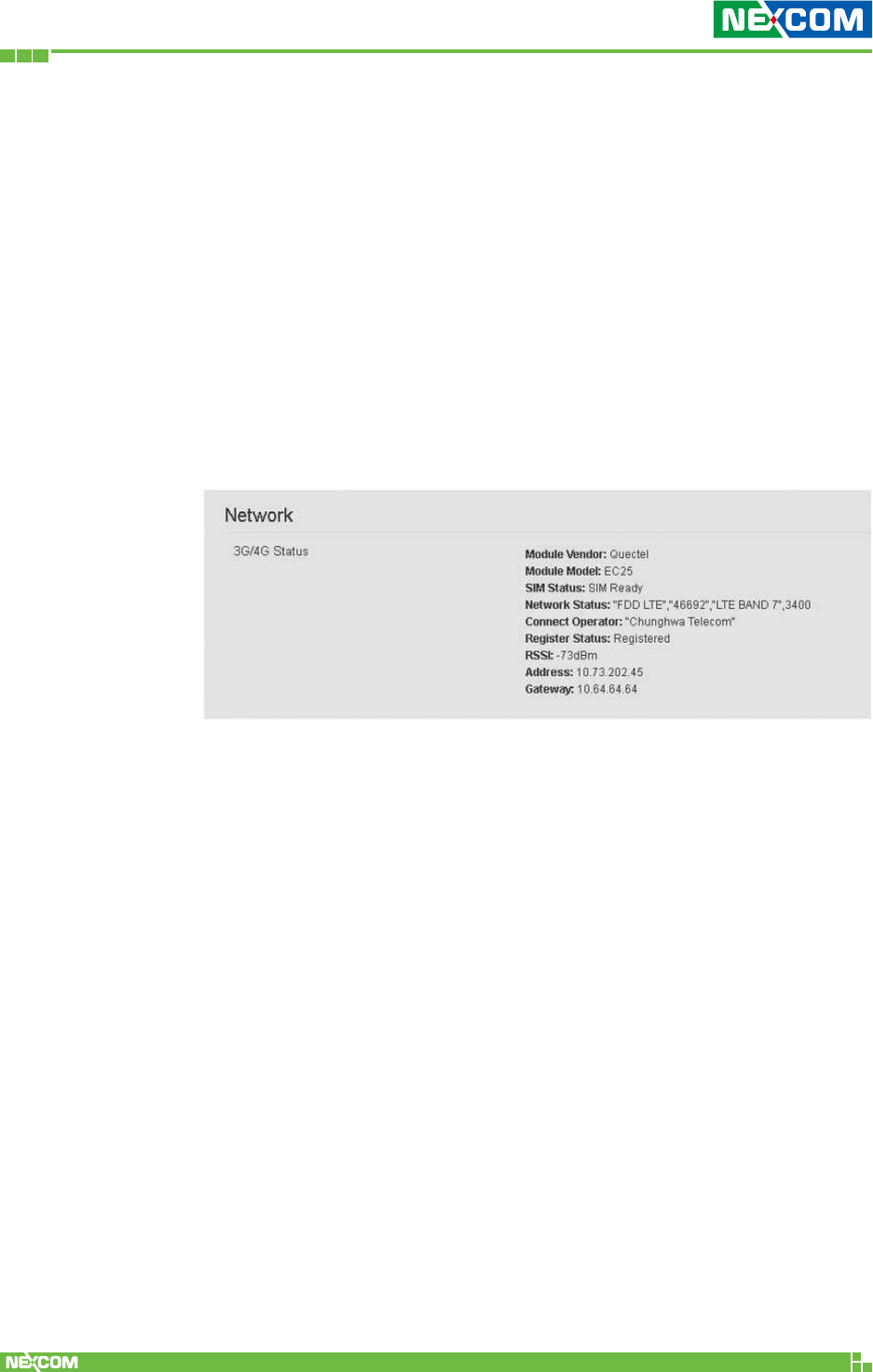
Check 3G/4G Connection Status
Please select “Status” -> “Overview”, and then check the 3G/4G status.
You can check the telecom operator’s IP and gateway, 3G/4G
information, etc.