NEXCOM VTC6110X00 Intelligent Vehicle Telematics Computer User Manual 1
NEXCOM international Co.,LTD Intelligent Vehicle Telematics Computer 1
NEXCOM >
Contents
- 1. User manual1
- 2. User manual2
- 3. User manual3
- 4. User manual4
- 5. User Manual4
User manual1

NEXCOM International Co., Ltd.
NEXCOM International Co., Ltd.
Published January 2010 www.nexcom.com
Mobile Computing Solutions
Vehicle Telematics Computer
VTC 6110
User Manual

Copyright © 2009 NEXCOM International Co., Ltd. All Rights Reserved. ii VTC 6110 User Manual
Contents
Co n t e n t s
Preface
Copyright ............................................................................................. iv
Disclaimer ............................................................................................. iv
Acknowledgements .............................................................................. iv
Regulatory Compliance Statements ....................................................... iv
Declaration of Conformity ...................................................................... iv
RoHS Compliance ................................................................................... v
Warranty and RMA ................................................................................ vi
Safety Information ................................................................................vii
Installation Recommendations ................................................................vii
Safety Precautions .................................................................................viii
Technical Support and Assistance ........................................................... ix
Conventions Used in this Manual ........................................................... ix
Global Service Contact Information ......................................................... x
Package Contents ..................................................................................xii
Ordering Information ............................................................................xiv
Chapter 1: Product Introduction
Overview ................................................................................................1
Key Features ...........................................................................................2
Hardware Specifications ..........................................................................2
COM Express CPU Module and Carrier Board ..........................................5
Physical Features .....................................................................................6
Front Panel ...........................................................................................6
Rear Panel ............................................................................................8
Mechanical Dimensions .........................................................................12
Chapter 2: Jumpers And Connectors
Before You Begin ..................................................................................13
Precautions ...........................................................................................13
Jumper .................................................................................................14
Locations of the Jumpers and Connectors .............................................15
VTCB6110 ..........................................................................................15
Jumper Settings ....................................................................................16
SW5: Input Voltage Selection ..............................................................16
SW6: COM Port Mode Selection .........................................................16
CF (IDE0) Primary Master/Slave Select (JP4)..........................................16
LVDS Power Input Voltage Select (JP9) ................................................16
CMOS Input Voltage Select (J6)...........................................................16
BIOS Function Select (J1) .....................................................................16
DC Input Voltage Select (JP1) ..............................................................16
Temp Sensor (JP8) ...............................................................................17
Auto Power Select (JP2) ......................................................................17
PCI-104 VI/O Select Voltage (J13) ........................................................17
MCU Download (JP6) .........................................................................17
GAL Download (JP5) ...........................................................................17
MCU COM Port (JP3) ..........................................................................17
Connectors ...........................................................................................18
COM Express Row A and Row B .........................................................18
COM Express Row C and Row D .........................................................20
CompactFlash Connector....................................................................22
GPIO Connector .................................................................................23
RS232 Connector: COM1, COM2 .......................................................23

Copyright © 2009 NEXCOM International Co., Ltd. All Rights Reserved. iii
Contents
VTC 6110 User Manual
RS232/485 Connector: COM3 ............................................................24
GAL Programmer PIN Header ..............................................................24
MCU Programmer Pin Header .............................................................25
VGA Connector ..................................................................................25
LVDS Connector + USB0 .....................................................................26
LAN Connector ...................................................................................27
USB Connector USB 1 .........................................................................27
USB Connector USB 2 .........................................................................28
LVDS Power Connector .......................................................................28
External 12V & 5V Power and SMBUS Connector ...............................29
Mic-in .................................................................................................29
Line-out ..............................................................................................30
PCI-104 VI/O Voltage Setting ..............................................................30
PCI-104 Connector .............................................................................31
Power Button .....................................................................................31
Reset Button .......................................................................................31
MCU COM Port ..................................................................................32
ACC_ON LED .....................................................................................32
Temp Sensor .......................................................................................33
DC Power Input Connector .................................................................33
Power On and IDE Active LED .............................................................34
GPIO and UMTS LEDs .........................................................................34
Serial ATA ...........................................................................................35
Serial ATA Power Input .......................................................................35
Mini-PCIe Socket (for 3.5G module) PCIe Interface..............................36
Mini-PCIe Socket (for WLAN module) USB + PCIe Interface .................36
SIM Card Connector ...........................................................................37
Bluetooth Connector ..........................................................................37
Chapter 3: System Setup
Removing the Chassis Cover ................................................................38
Installing a GPRS/UMTS/HSDPA Module ................................................39
Installing a Wireless LAN Module ..........................................................42
Installing a Bluetooth Module ...............................................................45
Installing a CompactFlash Card .............................................................47
Installing the PCI-104 Module ...............................................................49
Installing a SATA Hard Drive ..................................................................51
Installing the SODIMM ..........................................................................55
Installing the USB Cable Holder .............................................................57
Rackmount Brackets .............................................................................58
Appendix A: I/O Address Function
I/O Address Function .............................................................................59
Appendix B: ICES200-L24 COM Express CPU Module
Overview ..............................................................................................62
Key Features .........................................................................................62
Specifications ........................................................................................62
Mechanical Dimensions .........................................................................65
PCI Routing ...........................................................................................66
Connectors ...........................................................................................67
Appendix C: VTCB6110 Carrier Board
Specifications ........................................................................................72
Jumpers and Connectors .......................................................................73
Jumper Settings ...................................................................................74
Connectors ..........................................................................................76
Appendix D: Vehicle Power Management Setup
Vehicle Power Management Setup ........................................................96
Appendix E: Power Consumption
Power Consumption ...........................................................................103

Copyright © 2009 NEXCOM International Co., Ltd. All Rights Reserved. iv VTC 6110 User Manual
Preface
Pr e f a c e
Regulatory Compliance Statements
This section provides the FCC compliance statement for Class B devices
and describes how to keep the system CE compliant.
Declaration of Conformity
FCC
This equipment has been tested and verified to comply with the limits for
a Class B digital device, pursuant to Part 15 of FCC Rules. These limits are
designed to provide reasonable protection against harmful interference
when the equipment is operated in a commercial environment. This equip-
ment generates, uses, and can radiate radio frequency energy and, if not
installed and used in accordance with the instructions, may cause harmful
interference to radio communications. Operation of this equipment in a
residential area (domestic environment) is likely to cause harmful interfer-
ence, in which case the user will be required to correct the interference
(take adequate measures) at their own expense.
CE
The product(s) described in this manual complies with all applicable Euro-
pean Union (CE) directives if it has a CE marking. For computer systems to
remain CE compliant, only CE-compliant parts may be used. Maintaining
CE compliance also requires proper cable and cabling techniques.
Copyright
This publication, including all photographs, illustrations and software, is
protected under international copyright laws, with all rights reserved. No
part of this manual may be reproduced, copied, translated or transmitted
in any form or by any means without the prior written consent from
NEXCOM International Co., Ltd.
Disclaimer
The information in this document is subject to change without prior notice
and does not represent commitment from NEXCOM International Co., Ltd.
However, users may update their knowledge of any product in use by con-
stantly checking its manual posted on our website: http://www.nexcom.
com. NEXCOM shall not be liable for direct, indirect, special, incidental, or
consequential damages arising out of the use of any product, nor for any
infringements upon the rights of third parties, which may result from such
use. Any implied warranties of merchantability or fitness for any particular
purpose is also disclaimed.
Acknowledgements
VTC 6110 is a trademark of NEXCOM International Co., Ltd. All other
product names mentioned herein are registered trademarks of their respec-
tive owners.

Copyright © 2009 NEXCOM International Co., Ltd. All Rights Reserved. vVTC 6110 User Manual
Preface
e13 Mark
The “e” mark is the proof of compliance with directives (laws) required by
the European Union. The Council of European communities in Brussels issues
these directives and all members must accept approved products.
e13 - Luxembourg
For more information, visit http://www.tuv.com/jp/en/_e_mark_and_e_mark_
homologation_for_vehicles_vehicle_components_.html.
RoHS Compliance
NEXCOM RoHS Environmental Policy and Status
Update
NEXCOM is a global citizen for building the digital infra-
structure. We are committed to providing green products
and services, which are compliant with European Union
RoHS (Restriction on Use of Hazardous Substance in Electronic Equipment)
directive 2002/95/EU, to be your trusted green partner and to protect our
environment.
RoHS restricts the use of Lead (Pb) < 0.1% or 1,000ppm, Mercury (Hg)
< 0.1% or 1,000ppm, Cadmium (Cd) < 0.01% or 100ppm, Hexavalent
Chromium (Cr6+) < 0.1% or 1,000ppm, Polybrominated biphenyls (PBB) <
0.1% or 1,000ppm, and Polybrominated diphenyl Ethers (PBDE) < 0.1% or
1,000ppm.
In order to meet the RoHS compliant directives, NEXCOM has established an
engineering and manufacturing task force in to implement the introduction
of green products. The task force will ensure that we follow the standard
NEXCOM development procedure and that all the new RoHS components
and new manufacturing processes maintain the highest industry quality
levels for which NEXCOM are renowned.
How to recognize NEXCOM RoHS Products?
For existing products where there are non-RoHS and RoHS versions, the suf-
fix “(LF)” will be added to the compliant product name.
All new product models launched after January 2006 will be RoHS compli-
ant. They will use the usual NEXCOM naming convention.

Copyright © 2009 NEXCOM International Co., Ltd. All Rights Reserved. vi VTC 6110 User Manual
Preface
Warranty and RMA
NEXCOM Warranty Period
NEXCOM manufactures products that are new or equivalent to new in
accordance with industry standard. NEXCOM warrants that products will
be free from defect in material and workmanship for 2 years, beginning
on the date of invoice by NEXCOM. HCP series products (Blade Server)
which are manufactured by NEXCOM are covered by a three year warranty
period.
NEXCOM Return Merchandise Authorization (RMA)
Customers shall enclose the “NEXCOM RMA Service Form” with the ?
returned packages.
Customers must collect all the information about the problems encoun- ?
tered and note anything abnormal or, print out any on-screen messages,
and describe the problems on the “NEXCOM RMA Service Form” for
the RMA number apply process.
Customers can send back the faulty products with or without acces- ?
sories (manuals, cable, etc.) and any components from the card, such as
CPU and RAM. If the components were suspected as part of the prob-
lems, please note clearly which components are included. Otherwise,
NEXCOM is not responsible for the devices/parts.
Customers are responsible for the safe packaging of defective products, ?
making sure it is durable enough to be resistant against further damage
and deterioration during transportation. In case of damages occurred
during transportation, the repair is treated as “Out of Warranty.”
Any products returned by NEXCOM to other locations besides the cus- ?
tomers’ site will bear an extra charge and will be billed to the customer.
Repair Service Charges for Out-of-Warranty Products
NEXCOM will charge for out-of-warranty products in two categories, one
is basic diagnostic fee and another is component (product) fee.
System Level
Component fee: NEXCOM will only charge for main components such ?
as SMD chip, BGA chip, etc. Passive components will be repaired for
free, ex: resistor, capacitor.
Items will be replaced with NEXCOM products if the original one cannot ?
be repaired. Ex: motherboard, power supply, etc.
Replace with 3rd party products if needed. ?
If RMA goods can not be repaired, NEXCOM will return it to the cus- ?
tomer without any charge.
Board Level
Component fee: NEXCOM will only charge for main components, such ?
as SMD chip, BGA chip, etc. Passive components will be repaired for
free, ex: resistors, capacitors.
If RMA goods can not be repaired, NEXCOM will return it to the cus- ?
tomer without any charge.

Copyright © 2009 NEXCOM International Co., Ltd. All Rights Reserved. vii VTC 6110 User Manual
Preface
Warnings
Read and adhere to all warnings, cautions, and notices in this guide and
the documentation supplied with the chassis, power supply, and accessory
modules. If the instructions for the chassis and power supply are incon-
sistent with these instructions or the instructions for accessory modules,
contact the supplier to find out how you can ensure that your computer
meets safety and regulatory requirements.
Cautions
Electrostatic discharge (ESD) can damage system components. Do the de-
scribed procedures only at an ESD workstation. If no such station is avail-
able, you can provide some ESD protection by wearing an antistatic wrist
strap and attaching it to a metal part of the computer chassis.
Safety Information
Before installing and using the device, note the following precautions:
Read all instructions carefully. ▪
Do not place the unit on an unstable surface, cart, or stand. ▪
Follow all warnings and cautions in this manual. ▪
When replacing parts, ensure that your service technician uses parts ▪
specified by the manufacturer.
Avoid using the system near water, in direct sunlight, or near a heating ▪
device.
The load of the system unit does not solely rely for support from the ▪
rackmounts located on the sides. Firm support from the bottom is highly
necessary in order to provide balance stability.
The computer is provided with a battery-powered real-time clock circuit. ▪
There is a danger of explosion if battery is incorrectly replaced. Replace
only with the same or equivalent type recommended by the manufactur-
er. Discard used batteries according to the manufacturer’s instructions.
Installation Recommendations
Ensure you have a stable, clean working environment. Dust and dirt can
get into components and cause a malfunction. Use containers to keep
small components separated.
Adequate lighting and proper tools can prevent you from accidentally
damaging the internal components. Most of the procedures that follow
require only a few simple tools, including the following:
A Philips screwdriver•
A flat-tipped screwdriver•
A grounding strap•
An anti-static pad•
Using your fingers can disconnect most of the connections. It is recom-
mended that you do not use needlenose pliers to disconnect connections
as these can damage the soft metal or plastic parts of the connectors.

Copyright © 2009 NEXCOM International Co., Ltd. All Rights Reserved. viii VTC 6110 User Manual
Preface
Safety Precautions
1. Read these safety instructions carefully.
2. Keep this User Manual for later reference.
3. Disconnect this equipment from any AC outlet before cleaning. Use a
damp cloth. Do not use liquid or spray detergents for cleaning.
4. For plug-in equipment, the power outlet socket must be located near
the equipment and must be easily accessible.
5. Keep this equipment away from humidity.
6. Put this equipment on a stable surface during installation. Dropping
it or letting it fall may cause damage.
7. Do not leave this equipment in either an unconditioned environment
or in a above 40oC storage temperature as this may damage the
equipment.
8. The openings on the enclosure are for air convection to protect the
equipment from overheating. DO NOT COVER THE OPENINGS.
9. Make sure the voltage of the power source is correct before connect-
ing the equipment to the power outlet.
10. Place the power cord in a way so that people will not step on it. Do
not place anything on top of the power cord. Use a power cord that
has been approved for use with the product and that it matches the
voltage and current marked on the product’s electrical range label.
The voltage and current rating of the cord must be greater than the
voltage and current rating marked on the product.
11. All cautions and warnings on the equipment should be noted.
12. If the equipment is not used for a long time, disconnect it from the
power source to avoid damage by transient overvoltage.
13. Never pour any liquid into an opening. This may cause fire or electri-
cal shock.
14. Never open the equipment. For safety reasons, the equipment should
be opened only by qualified service personnel.
15. If one of the following situations arises, get the equipment checked
by service personnel:
a. The power cord or plug is damaged.
b. Liquid has penetrated into the equipment.
c. The equipment has been exposed to moisture.
d. The equipment does not work well, or you cannot get it to work
according to the user’s manual.
e. The equipment has been dropped and damaged.
f. The equipment has obvious signs of breakage.
16. Do not place heavy objects on the equipment.
17. The unit uses a three-wire ground cable which is equipped with a
third pin to ground the unit and prevent electric shock. Do not defeat
the purpose of this pin. If your outlet does not support this kind of
plug, contact your electrician to replace your obsolete outlet.
18. CAUTION: DANGER OF EXPLOSION IF BATTERY IS INCORRECTLY
REPLACED. REPLACE ONLY WITH THE SAME OR EQUIVALENT TYPE
RECOMMENDED BY THE MANUFACTURER. DISCARD USED BATTER-
IES ACCORDING TO THE MANUFACTURER’S INSTRUCTIONS.
19. The computer is provided with CD drives that comply with the ap-
propriate safety standards including IEC 60825.
Copyright © 2009 NEXCOM International Co., Ltd. All Rights Reserved. ix VTC 6110 User Manual
Preface
Conventions Used in this Manual
Warning: Information about certain situations, which if not
observed, can cause personal injury. This will prevent injury to
yourself when performing a task.
Caution: Information to avoid damaging components or losing
data.
Note: Provides additional information to complete a task easily.
Technical Support and Assistance
1. For the most updated information of NEXCOM products, visit NEX-
COM’s website at www.nexcom.com.
2. For technical issues that require contacting our technical support team
or sales representative, please have the following information ready
before calling:
– Product name and serial number
– Detailed information of the peripheral devices
– Detailed information of the installed software (operating system,
version, application software, etc.)
– A complete description of the problem
– The exact wordings of the error messages
Warning!
1. Handling the unit: carry the unit with both hands and handle it with
care.
2. Maintenance: to keep the unit clean, use only approved cleaning prod-
ucts or clean with a dry cloth.
3. CompactFlash: Turn off the unit’s power before inserting or removing a
CompactFlash storage card.

Copyright © 2009 NEXCOM International Co., Ltd. All Rights Reserved. x
Preface
VTC 6110 User Manual
Headquarters
Taiwan
18F, No. 716, Chung-Cheng Rd. Chung-Ho City,
Taipei County 235, Taiwan, R.O.C.
Tel: +886-2-8228-0606
Fax: +886-2-8228-0501
http://www.nexcom.com.tw
USA
3758 Spinnaker Court,
Fremont, CA 94538, USA
Tel: +1-510-656-2248
Fax: +1-510-656-2158
http://www.nexcom.com
France
Z.I. des Amandiers, 17, Rue des entrepreneurs
78420 Carrières sur Seine, France
Tel: +33 (0)1 71 51 10 20
Fax: +33 (0)1 71 51 10 21
http://www.nexcom.eu
Global Service Contact Information
Germany
Leopoldstrase Business Centre, Leopoldstrase 244 80807
Munich, Germany
Tel: +49-89-208039-278
Fax: +49-89-208039-279
http://www.nexcom.eu
Italy
Via Gaudenzio Ferrari 29, 21047 Saronno (VA) Italia
Tel: +39 02 9628 0333
Fax: +39 02 9619 8846
http://www.nexcom.eu
United Kingdom
10 Vincent Avenue, Crownhill Business Centre
Milton Keynes, Buckinghamshire, MK8 0AB
United Kingdom
Tel: +44-1908-267121
Fax: +44-1908-262042
http://www.nexcom.eu

Copyright © 2009 NEXCOM International Co., Ltd. All Rights Reserved. xi
Preface
VTC 6110 User Manual
Japan
10F, Nakagin-Shiroyama Building, 8-16-13.
Ginza Chuou-ku, Tokyo 104-0061, Japan
Tel: +81-3-3524-4250
Fax: +81-3-3524-4252
http://www.nexcom-jp.com
China-Beijing
Room 301, Block E, Power Creative Building, No. 1
Shangdi East Rd. Haidian Dist., Beijing, 100085, China
Tel: +86-10-5885-6655
Fax: +86-10-5885-1066
http://www.nexcom.cn
China-Shanghai Office
Room 1505, Greenland He Chuang Building, No. 450
Caoyang Rd. Shanghai, 200063, China
Tel: +86-21-6150-8008
Fax: +86-21-3251-6358
http://www.nexcom.cn
China-Nanjing Office
Room 1206, Hongde Building, No. 20 Yunnan Rd.
Nanjing, 210018, China
Tel: +86-25-8324-9606
Fax: +86-25-8324-9685
http://www.nexcom.cn
China-Shenzhen Office
Western Room 708, Block 210, Tairan Industry & Trading Place,
Futian Area, Shenzhen, China 518040
TEL: +86-755-833 27203
FAX: +86-755-833 27213
http://www.nexcom.cn
Copyright © 2009 NEXCOM International Co., Ltd. All Rights Reserved. xii
Preface
VTC 6110 User Manual
Pa c k a g e co n t e n t s
Before continuing, verify that the VTC 6110 package that you received is complete. Your VTC 6110 package should have all the items listed in the following
table.
Item P/N Name Specification Qty
1 4NCPM00302X00 POWER CON 3P PHOENIX CONTACT 1
2 5060100017X00 DAMPER 6mm/OUTSIDE DIA .12mm H: 9mm TPS(BLACK) 4
3 50311F0119X00 I HEAD BOLTS SCREW LONG I3x12.5 AXISx 8.5mm SCREWx 4mm 4
4 60233PW134X00 (N)POWER CABLE FOR VTK33B SMBUS SIGNAL 1
5 60233ATA10X00 SATA CABLE L: 70mm 1
6 60233PW102X00 SATA POWER CABLE SATA 15PIN TO 3022H-04 4PIN PITCH 5.08mm ,L: 80mm 1
7 5042220027X00 (N)WIRE MOUNT 19.1x8.4x1.3 NYLON66 3
8 50311F0150X00 (N)F HEAD SCREW LONG #6-32X8 NI NYLOK 3
9 60233SAM05X00 GPS ANTENNA 5M /SMA180P 1
10 50311F0100X00 ROUND HEAD SCREW W/SPRING+FLAT WASHER
LONG
P3x6 iso/SW6x0.5 NI 4
Copyright © 2009 NEXCOM International Co., Ltd. All Rights Reserved. xiii
Preface
VTC 6110 User Manual
Item P/N Name Specification Qty
11 5043330247X00 HDD BRACKET 129.5x97x 1mm 1
12 5043330246X00 HDD BRACKET FOR CUSHION LEFT 123.3x44.5x 14.7mm 1
13 5043330245X00 HDD BRACKET FOR CUSHION RIGHT 128.5x17x 1mm 1
14 50344C0067X00 COPPER POST LONG WITH MALE/FEMALE (FEMALE)16mmx(MALE)5mmxM3 4
15 5060100012X00 HIGH-END DAMPER INSIDE 11.1mm H: 10.8mm TPS(BLACK) 4
16 50311F0107X00 I HEAD BOLTS SCREW LONG I3x14 AXISx 10mm SCREWx 4mm (BLACK) 4
17 602DCD0256X00 CD driver 1

Copyright © 2009 NEXCOM International Co., Ltd. All Rights Reserved. xiv
Preface
VTC 6110 User Manual
or d e r i n g in f o r m a t i o n
The following provides ordering information for VTC 6110.
VTC 6110 (P/N: 10V00611000X0)•
- with Intel Core™ Duo L2400, 1GB DDR2 memory, GPS module and
GPS antenna
Copyright © 2009 NEXCOM International Co., Ltd. All Rights Reserved. 1VTC 6110 User Manual
Chapter 1: Product Introduction
Ch a p t e r 1: pr o d u C t In t r o d u C t I o n
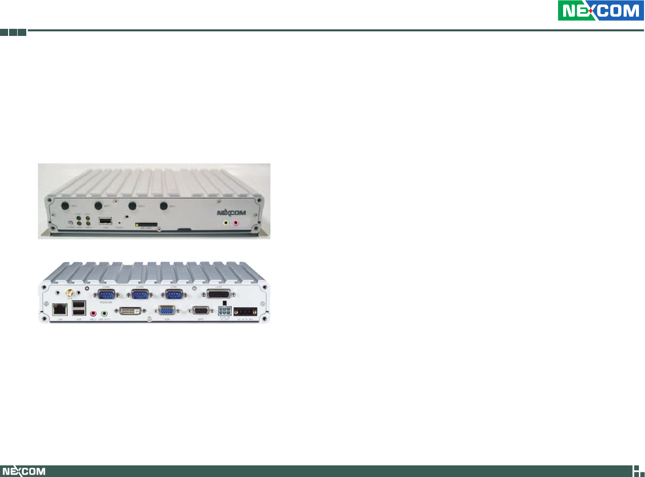
Overview
Front View
Rear View
The VTC6110 is an innovative in-vehicle computer for use in any car, truck,
or even for maritime applications. The design itself makes the system
available as a complete system allowing the user to easily define and build
requirements.
VTC6110 fulfills vehicle industry requirements. The design itself is in
compliance with vehicle industrial standard such as eMark. More features
required for in-vehicle operations, such as power ignition delay control,
low-power protection and SMBus connection, etc., are continued from
NEXCOM’s other in-vehicle computer products.
The GPS function navigates drivers to ultimate the fleet management. Op-
tional 802.11b/g/n, 3.5G, GPRS, and Bluetooth availability make VTC6110
ready for wider coverage and future trend. Multiple display connections
make VTC6110 an ideal choice for in-vehicle signage platforms as well.

Copyright © 2009 NEXCOM International Co., Ltd. All Rights Reserved. 2VTC 6110 User Manual
Chapter 1: Product Introduction
Key Features
Built-in Intel• ® Core™ Duo LV processor
Fanless design with ruggedized aluminum chassis•
2 Mini PCI Express and 1 PCI-104 expansions•
Wide range DC input from 6V to 36V•
Power ignition on/off delay controlled by software•
Low battery power protection setting by software•
External smart battery back-up support•
S3 & S4 suspend mode support•
Availability of GPS, GPRS/UMTS/HSDPA•
Multiple display connections thru VGA, DVI-D and LVDS•
Optional IP65 enclosure•
e13 Mark certification•
Hardware Specifications
COM Express CPU Module (ICES200-L24)
Intel• ® Core™ Duo L2400
VGA/PCI/PCIe/LVDS/Audio/COM/LPT/USB2.0/LAN interface•
Memory
Supports DDR2 533/667 non-ECC, non-registered SDRAM •
One 200-pin SO-DIMM supports up to 2GB memory•
Chipset
Intel 945GME / ICH7M•
Expansion
2 Mini PCI Express slots•
- 1 x (PCIe + USB) for WLAN card
- 1 x PCIe for HSDPA module or GPRS module
1 PCI-104 slot•
1 Bluetooth module (optional)•
I/O Interfaces - Front
Logo plate•
1 x Power button (w/ LED)•
1 x Reset button•
1 x SIM card socket•
1 x USB 2.0•
1 x Power LED•
1 x HDD LED•
1 x GPIO LED - programmable for alarm or other application specific •
purposes
1x LED for COMM (WLAN/HSDPA) status•
Antenna mounting holes for 4x SMA-type (WLAN, HSDPA and Blu-•
etooth)
1 x Line-out•
1 x Mic-in•
I/O Interfaces - Rear
COM ports•
- 1 x DB9 COM1 RS232
- 1 x DB9 COM2 RS232
- 1 x DB9 COM3 RS232/485 w/ auto flow control
1 x DB26 LVDS (w/ +12V for backlight power and USB2.0)•
1 x DB15 VGA•
1 x DVI-D•
2 x USB•
1 x Realtek 10/100/1000 Ethernet•
2 x Mic-in and 2 Line-out (ALC888-VC2-GR HD Codec, AC’97 Compat-•
ible)

Copyright © 2009 NEXCOM International Co., Ltd. All Rights Reserved. 3VTC 6110 User Manual
Chapter 1: Product Introduction
6V (15A) to 36V (5A) thru DC 3-pin power input connector (ignition, •
power input and ground)
1 x DB9 Female for digital I/O with 4-input and 4-output•
+5 VDC (1A) and +12VDC (1A) power output and SMBus (w/o VTK •
33M-01 connection)
+5 VDC (0.5A) and +12VDC (0.5A) power output and SMBus (w/ VTK
33M-01 connection)
Expandable Storage
1 x 2.5” SATA HDD drive bay •
1 Type II CompactFlash socket (IDE)-•
Contruction
Aluminum enclosure with fanless design•
Protection Class
IP65 compliant (w/ optional IP65 kit)•
Certifications
CE, FCC Class B, e13 Mark, EN50155•
Dimensions
260mm(W) x 176mm(D) x 50mm(H) (10.24” x 7” x 1.97”)•
Environment
W/O Vibration Kit
Operating Temperatures:•
Ambient with air: -30°C to 50°C (CF/SSD); -30°C to 50°C (HDD)
Storage temperature: -40°C to 80°C •
Relative humidity: 10% to 90% (Non-condensing)•
Vibration (random): 2g @ 5~500 Hz with CF/SSD; 1g @ 5~500 Hz with •
Automotive HDD (in operation)
Vibration•
Operating: MIL-STD-810F, Method 514.5, Category 20, Ground Vehicle
– Highway Truck
C-17, 0.04 g2/Hz at 20-1000 Hz, -6 dB/Octave at 1000-2000 Hz
Tested MIL-STD-810F method 514.5
Storage: MIL-STD-810F, Method 514.5, Category 24, Integrity Test
Shock:
Operating: MIL-STD-810F, Method 516.5, Procedure I, Trucks and semi-
trailers=20g
Crash Hazard: MIL-STD-810F, Method 516.5, Procedure V, Ground
equipment = 75g
OS Support
Vista, XP, XPe, Linux 2.6•

Copyright © 2009 NEXCOM International Co., Ltd. All Rights Reserved. 4VTC 6110 User Manual
Chapter 1: Product Introduction
Power Management
Power-on delay time is selectable by BIOS to disable and enable in 10sec •
/ 30sec / 1min / 5min / 10 min / 15min / 30min / 1hr.
Power-off delay time is selectable by BIOS to disable and enable in 20sec •
/ 1min / 5min / 10min / 30min / 1hr / 6hr / 18hr.
S3, S4 suspend mode•
•IgnitionOn/OffstatusdetectablebySW
•LowbatterystatusdetectablebySW
Ignition enable/disable is jumper selectable•
Shut down system automatically when the system’s internal temperature •
is over 80C.
VTC 6110 will automatically shut down 5 minutes after the duration •
of low battery voltage is over 60 sec. User can detect this situation via
software.
If the ignition is off and the system is still on after 3 minutes, VTC 6110 •
will shut down automatically.
If the ignition is off, the user can detect this status via the software. •
If the ignition is turned on again and the power-off delay is in progress, •
VTC 6110 will cancel the delay function and will continue to operate
normally.
If the ignition is turned on again and the power-off delay ended, VTC •
6110 will shut down completely will power-on again automatically.
If the ignition is turned off again and power-on delay is in progress, VTC •
6110 will cancel the delay and stay in power-off status.
If the ignition is turned off again and the power-on delay ended (en-•
tered OS already), VTC 6110 will continue to operate normally.
If the ignition is turned off again and the power-on delay ended (in BIOS •
process), VTC 6110 will shut down immediately.
If VTC 6110 is off, only below 10mA is used.•

Copyright © 2009 NEXCOM International Co., Ltd. All Rights Reserved. 5VTC 6110 User Manual
Chapter 1: Product Introduction
COM Express CPU Module and Carrier Board
The VTC 6110 system uses the ICES200-L24 COM Express CPU module
and the VTCB6110 carrier board.
ICES200-L24 COM Express CPU Module
ICES200-L24 is a COM Express CPU module that uses the Intel® 945GME
chipset and supports Intel® Core™ Duo L2400.
The module also supports one unbuffered non-ECC 533/667 DDR2 SO-
DIMM with maximum memory size up to 2GB. The Intel® 945GME chipset
supports the following interfaces: PCI, PCIe, SATA, VGA, LVDS, LAN, Serial,
USB, etc.
The ICES200-L24 module is based on the COM Express basic form factor
Type 2 standard, x2 connections between the COM Express CPU module
and the I/O carrier board.
The ICES200-L24 CPU module can easily integrate into most of the limited-
space devices such as industrial automation, data acquisition and equip-
ment computers.
VTCB6110 Carrier Board
Key features:
Quick customizable COM Express architecture platform•
Wide varieties of built-in communication and I/O ports specially de-•
signed for Transport Application
Customizable delay time for power-on and power-off•
Three external serial port interfaces with two RS232 and one RS232/485•
Supports 10/100/1000 LAN,VGA Console, LVDS and GPIO•
3 x USB 2.0 ports•
Supports PCI-104 expansion•
Copyright © 2009 NEXCOM International Co., Ltd. All Rights Reserved. 6VTC 6110 User Manual
Chapter 1: Product Introduction
2. Mode B. When the ignition is from “low” to “high”, you can turn on
VTC 6110 only by pressing the power button. When the ignition is
“high”, you can press the power button to turn on/off VTC 6110.
If the ignition is from “high” to “low”, VTC 6110 will turn off automati-
cally. When the ignition is “low”, pressing the power button will not
turn on VTC 6110.
Normal PC Mode
3. Mode C. When there is power input, you can turn on VTC 6110 only
by pressing the power button. Ignition signal will not power on/off VTC
6110.
4. Mode D. When there is power input, VTC 6110 will turn on automati-
cally. Ignition signal will not power on/off VTC 6110.
Startup and Shutdown Mode (Refer to SW5 setting)
The start up and shut down setting modes are as follows.
1. Mode A (default setting). When the input power voltage is 12V, use
SW5 to select this voltage. Use the BIOS to select the start up and shut
down voltages.
2. Mode B. When the input power voltage is 24V, use SW5 to select this
voltage. Use the BIOS to select the start up and shut down voltages.
3. Mode C. The working input power voltage is 6V~36V. Start up and shut
down voltages settings are disabled. When using external battery kit
(VTK33B), mode C setting is required.
Power Button
There are 4 types of power on/off mode. Use JP1 and JP2 to select a mode.
(refer to the Internal Jumpers and Connectors section for details).
Vehicle PC Mode
1. Mode A (default setting). When the ignition is from “low” to “high”,
VTC 6110 will turn on automatically. When the ignition is “high”, press
the power button to turn on/off VTC 6110.
When the ignition is from “high” to “low”, VTC 6110 will turn off auto-
matically. When the ignition is “low”, pressing the power button will
not turn on VTC 6110.
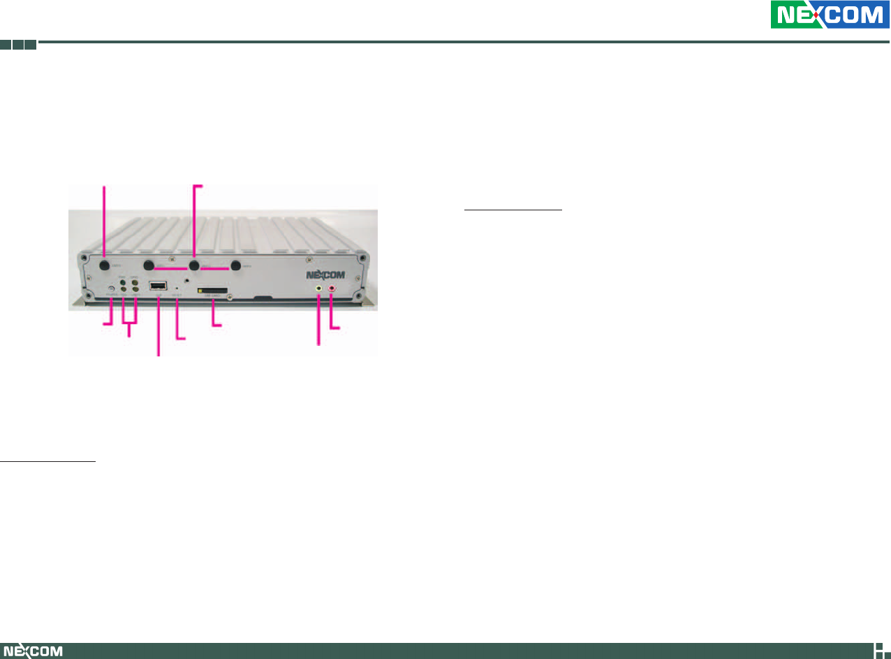
Physical Features
Front Panel
GPRS/UMTS/HSDPA module
antenna mounting holes WiFi/Bluetooth module
antenna mounting holes
Power button
LEDs
USB
Reset button
SIM card socket
Line-out
Mic-in