NEXCOM VTC6110X00 Intelligent Vehicle Telematics Computer User Manual 3
NEXCOM international Co.,LTD Intelligent Vehicle Telematics Computer 3
NEXCOM >
Contents
- 1. User manual1
- 2. User manual2
- 3. User manual3
- 4. User manual4
- 5. User Manual4
User manual3
Copyright © 2009 NEXCOM International Co., Ltd. All Rights Reserved. 27
Chapter 2: Jumpers and Connectors
VTC 6110 User Manual
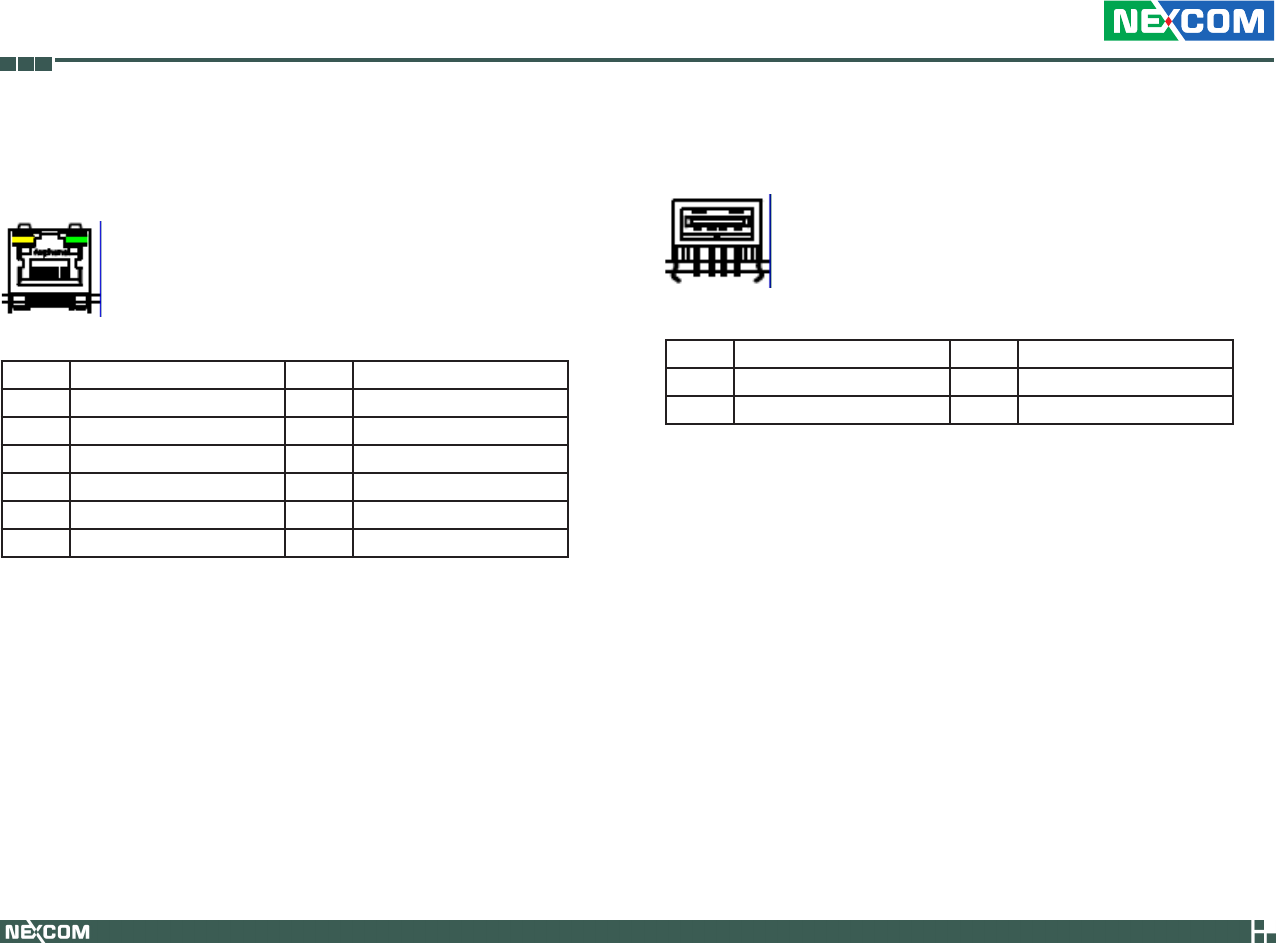
LAN Connector
Connector size: RJ-45
Connector location: LAN1
Connector Pin Definition
Pin Definition Pin Definition
1 TX+ 2 TX-
3 RX+ 4 N/C1
5 N/C2 6 RX-
7 N/C3 8 N/C4
9 LAN Speed LED 10 +3.3V
11 LAN Link LED 12 +3.3V
USB Connector
Connector location: USB1
Connector Pin Definition
Pin Definition Pin Definition
1 VCC 2 DATA-
3 DATA+ 4 GND
Copyright © 2009 NEXCOM International Co., Ltd. All Rights Reserved. 28
Chapter 2: Jumpers and Connectors
VTC 6110 User Manual
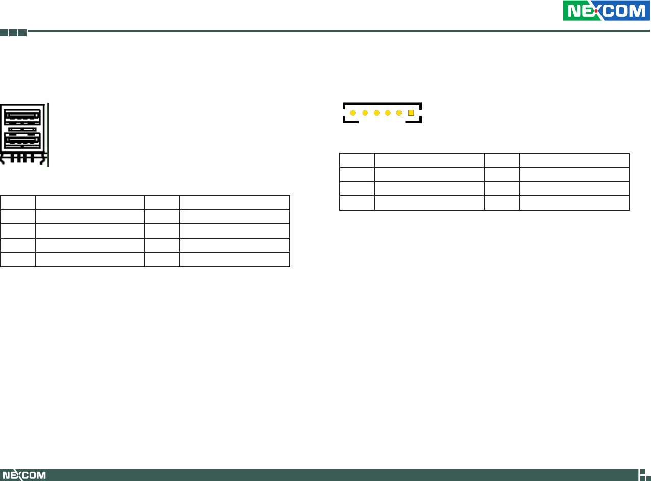
Connector Pin Definition
Pin Definition Pin Definition
1 VCC 2 DATA1-
3 DATA1+ 4 GND
5 VCC 6 DATA-
7 DATA+ 8 GND
USB Connector
Connector location: USB2
LVDS Power Connector
Connector location: J5
1
Connector Pin Definition
Pin Definition Pin Definition
1 Panel_backlight 2 Panel_VDD
3 GND 4 GND
5 LVDS_PANEL 6 LVDS_BIASON
Copyright © 2009 NEXCOM International Co., Ltd. All Rights Reserved. 29
Chapter 2: Jumpers and Connectors
VTC 6110 User Manual
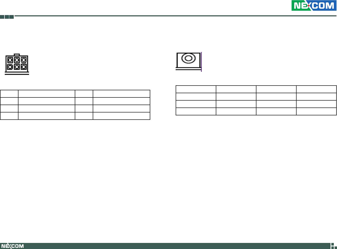
External 12V & 5V Power and SMBUS Connector
Connector location: CN2
6
3
4
1
Connector Pin Definition
Pin Definition Pin Definition
1 5V 2 12V
3 SMBCLK 4 GND
5 GND 6 SMBDATA
Mic-in
Connector location: CN11 and CN15
Connector Pin Definition
Pin Definition Pin Definition
1 NC 2 MIC_JD
3 NC 4 MIC_OUT
5 GND 6 GND
Copyright © 2009 NEXCOM International Co., Ltd. All Rights Reserved. 30
Chapter 2: Jumpers and Connectors
VTC 6110 User Manual
Line-out
Connector location: CN8 and CN14
Connector Pin Definition
Pin Definition Pin Definition
1 LINE_OUT_L 2 SURR_JD
3 NC 4 LINE_OUT_R
5 GND 6 GND
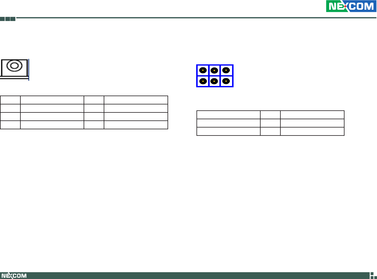
PCI-104 VI/O Voltage Setting
Connector location: J13
Connector Pin Definition
Pin No. Status Function Description
1-3, 2-4 (default) Short +3.3V
3-5, 4-6 Short +5V
4 62
3 51

Copyright © 2009 NEXCOM International Co., Ltd. All Rights Reserved. 31
Chapter 2: Jumpers and Connectors
VTC 6110 User Manual
PCI-104 Connector
Connector location: CN16
Connector Pin Definition
Power Button
Connector location: SW1
Reset Button
Connector location: SW2
Copyright © 2009 NEXCOM International Co., Ltd. All Rights Reserved. 32
Chapter 2: Jumpers and Connectors
VTC 6110 User Manual
MCU COM Port
Connector location: JP3
Connector Pin Definition
Pin Function Description
1 TX
2 RX
3 GND
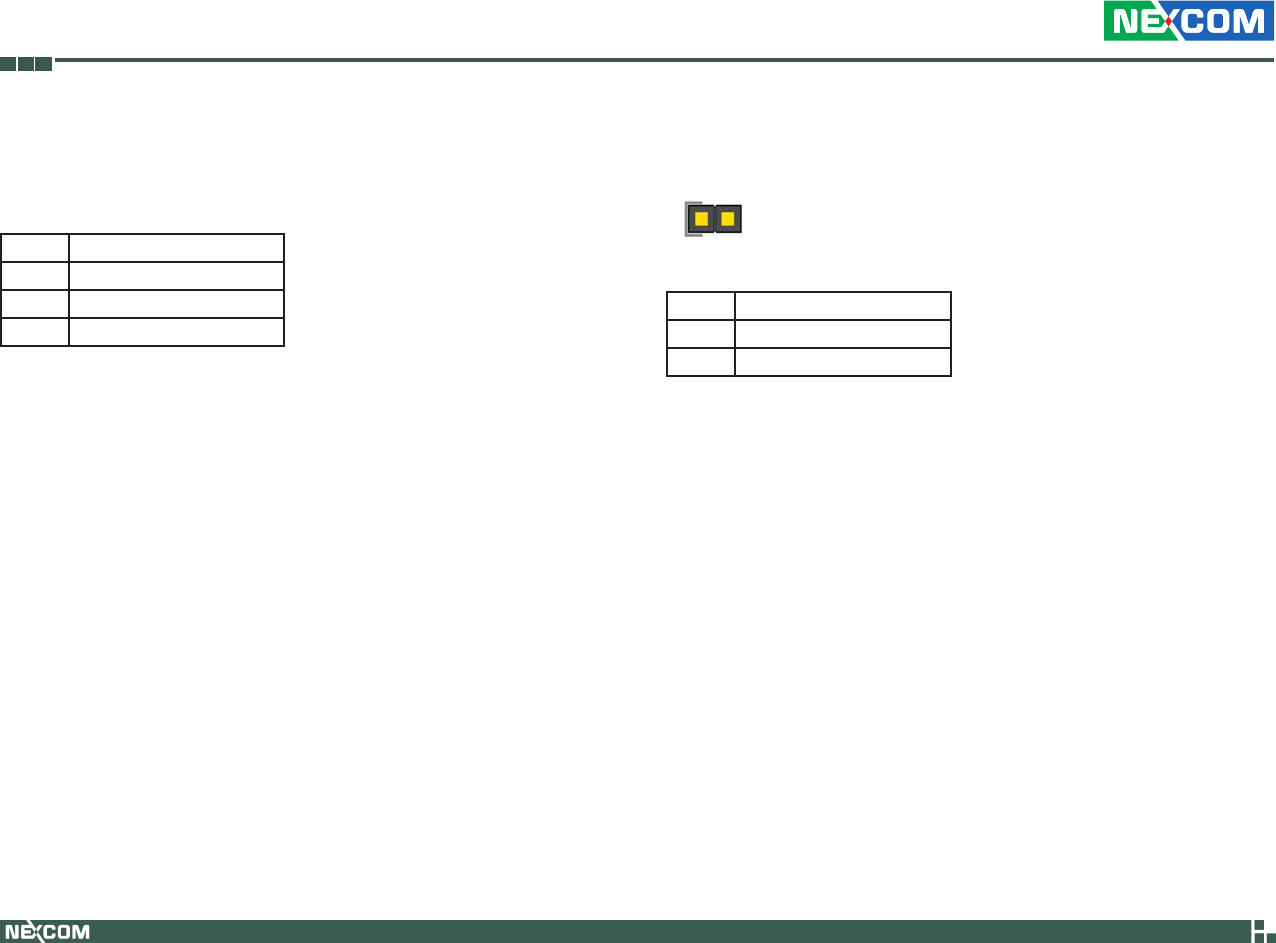
ACC_ON LED
Connector location: JP7
1
Connector Pin Definition
Pin Function Description
1 +3.3V LED
2 GND
Copyright © 2009 NEXCOM International Co., Ltd. All Rights Reserved. 33
Chapter 2: Jumpers and Connectors
VTC 6110 User Manual
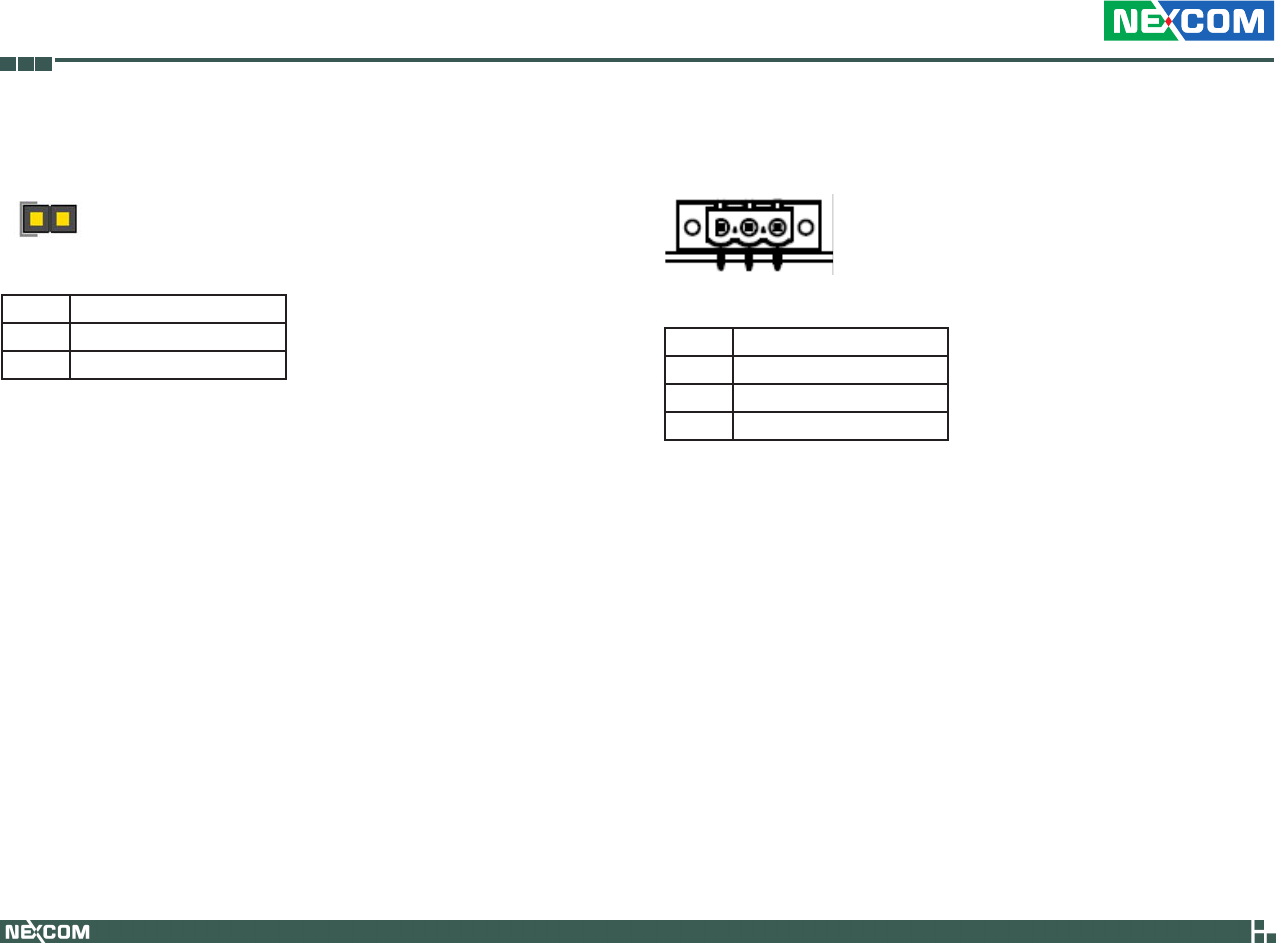
Temp Sensor
Connector location: JP8
1
Connector Pin Definition
Pin Function Description
1 SENSOR+
2 GND
DC Power Input Connector
Connector location: CN1
Connector Pin Definition
Pin Function Description
1 GND
2 VIN (6V~36V)
3 IGNITION
Copyright © 2009 NEXCOM International Co., Ltd. All Rights Reserved. 34
Chapter 2: Jumpers and Connectors
VTC 6110 User Manual
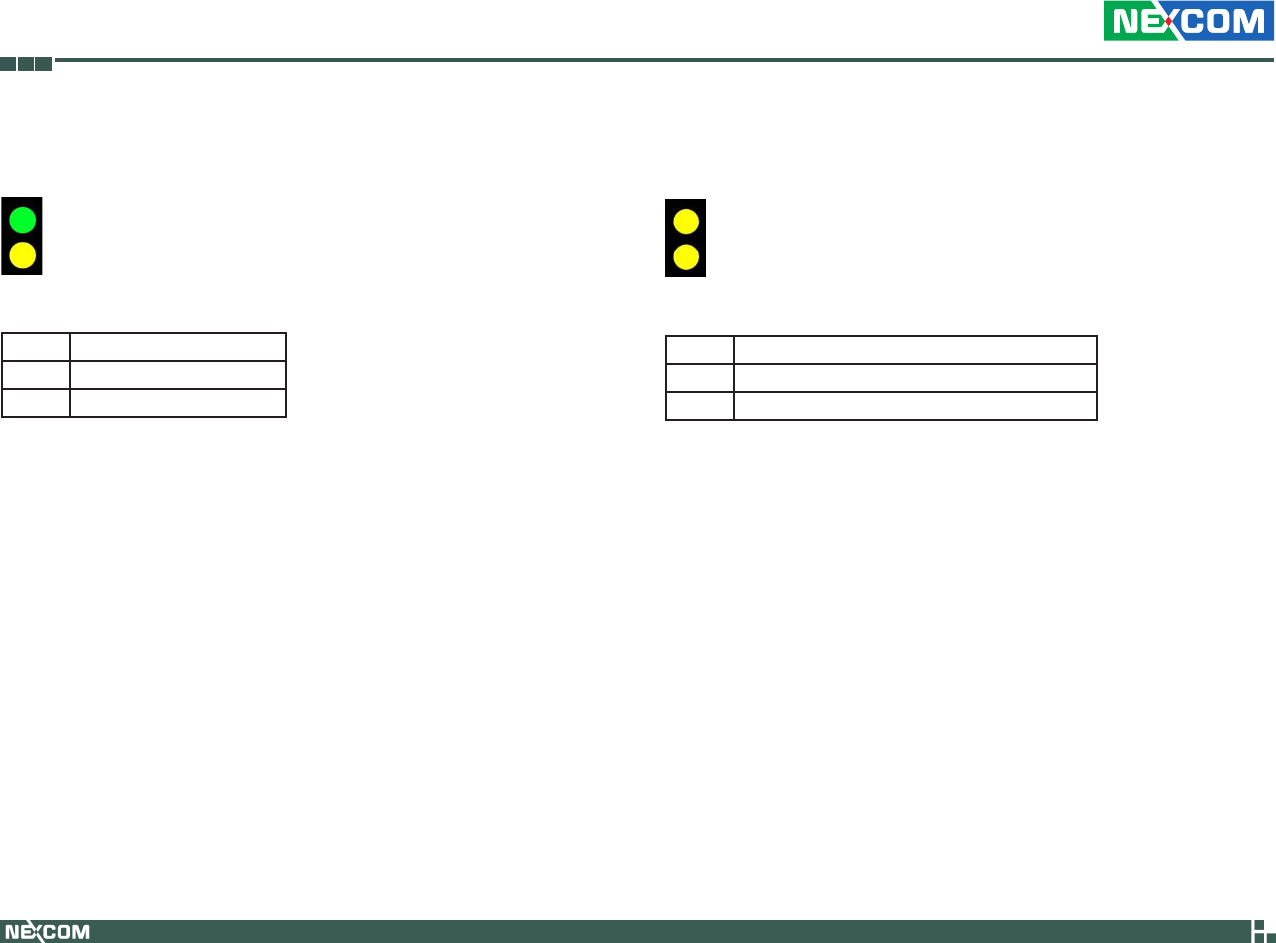
Power On and IDE Active LED
Connector location: LED1
T1
B1
Connector Pin Definition
LED Function Description
T1 POWER LED
B1 HD LED
GPIO and UMTS LEDs
Connector location: LED2
T2
B2
LED I/O Port Address and Data
LED Function Description
T2 I/O PORT Address: 0EE0; Bit0: 1 (Light), 0 (Dark)
B2 UMTS STATUS
Copyright © 2009 NEXCOM International Co., Ltd. All Rights Reserved. 35
Chapter 2: Jumpers and Connectors
VTC 6110 User Manual
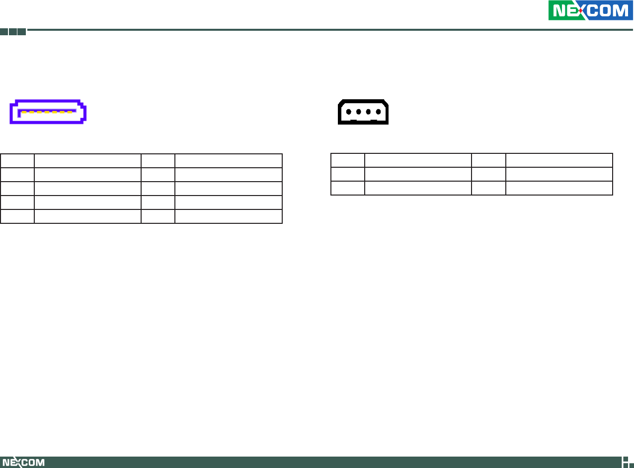
Serial ATA
Connector location: CN6
17
Connector Pin Definition
Pin Definition Pin Definition
1 GND 2 SATA_TXP0 -
3 SATA_TXN0 4 GND
5 SATA_RXN0 6 SATA_RXP0
7 GND
Serial ATA Power Input
Connector location: J10
1
4
Connector Pin Definition
Pin Definition Pin Definition
1 +V12S 2 GND
3 GND 4 +V5S

Copyright © 2009 NEXCOM International Co., Ltd. All Rights Reserved. 36
Chapter 2: Jumpers and Connectors
VTC 6110 User Manual
Mini-PCIe Socket (for 3.5G module)
PCIe Interface
Connector location: CN10
1
2
51
52
Connector Pin Definition
Pin Definition Pin Definition Pin Definition Pin Definition
1 MIC + 2 +V3.3S 27 GND 28 NC
3 MIC - 4 GND 29 GND 30 NC
5 SPK + 6 NC 31 NC 32 NC
7 GND 8 USIM PWR 33 RESET 34 GND
9 GND 10 USIM DATa 35 GND 36 USB_D-
11 VCC_
MSM26_
DIG
12 USIM CLK 37 GND 38 USB_D+
13 NC 14 USIM RST 39 +V3.3S 40 GND
15 GND 16 NC 41 +V3.3S 42 LED_
WWAN#
17 NC 18 GND 43 GND 44 NC
19 NC 20 W_DIS-
ABLE#
45 NC 46 NC
21 GND 22 NC 47 NC 48 NC
23 NC 24 NC 49 NC 50 GND
25 NC 26 GND 51 NC 52 +V3.3S
Mini-PCIe Socket (for WLAN module)
USB + PCIe Interface
Connector location: CN13
1
2
51
52
Connector Pin Definition
Pin Definition Pin Definition Pin Definition Pin Definition
1 WAKE# 2 +V3.3S 27 GND 28 +V1.5S
3 NC 4 GND 29 GND 30 SMB_CLK
5 NC 6 +V1.5S 31 PETn0 32 SMB_DATA
7 CLKREQ# 8 NC 33 PETp0 34 GND
9 GND 10 NC 35 GND 36 USB_D-
11 REFCLK- 12 NC 37 NC 38 USB_D+
13 REFCLK+ 14 NC 39 NC 40 GND
15 GND 16 NC 41 NC 42 LED_
WWAN#
17 NC 18 GND 43 NC 44 LED_
WLAN#
19 NC 20 DISABLE# 45 NC 46 LED_
WPAN#
21 GND 22 PERST# 47 NC 48 +V1.5S
23 PERn0 24 +3.3S 49 NC 50 GND
25 PERp0 26 GND 51 NC 52 +V3.3S

Copyright © 2009 NEXCOM International Co., Ltd. All Rights Reserved. 37
Chapter 2: Jumpers and Connectors
VTC 6110 User Manual
SIM Card Connector
Connector location: CN4
Connector Pin Definition
Pin Definition Pin Definition
C1 POWER VOLTAGE C2 RESET SIGNAL
C3 CLOCK SIGNAL C5 GND
C6 VPP:PROGRAM VOLTAGE C7 I/O
SW Contact present switch
Bluetooth Connector
Connector location: J7
J7
JST-1mm-M-90
1
2
3
MH1
MH2
4
5
6
10
9
8
7
Pin Definition Pin Definition
1 GND 2 USB_6P_L
3 USB_6N_L 4 NC
5 NC 6 BT_AUDIO_EN_R
7 NC 8 BT_3.3V
9 NC 10 GND
Copyright © 2009 NEXCOM International Co., Ltd. All Rights Reserved. 38
Chapter 3: System Setup
VTC 6110 User Manual
Ch a p t e r 3: Sy S t e m Se t u p
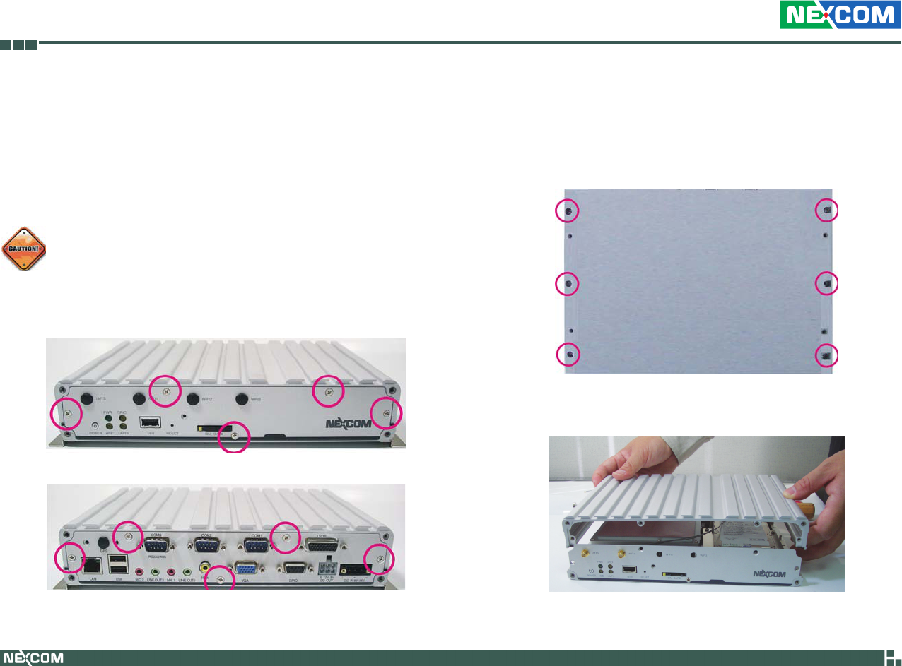
Removing the Chassis Cover
Front View
2. Lift the cover upward then remove it from the chassis.
Bottom View
Prior to removing the chassis cover, make sure the unit’s power is
off and disconnected from the power sources to prevent electric
shock or system damage.
1. The screws on the cover are used to secure the cover to the chassis.
Remove these screws and put them in a safe place for later use.
Rear View
Copyright © 2009 NEXCOM International Co., Ltd. All Rights Reserved. 39
Chapter 3: System Setup
VTC 6110 User Manual
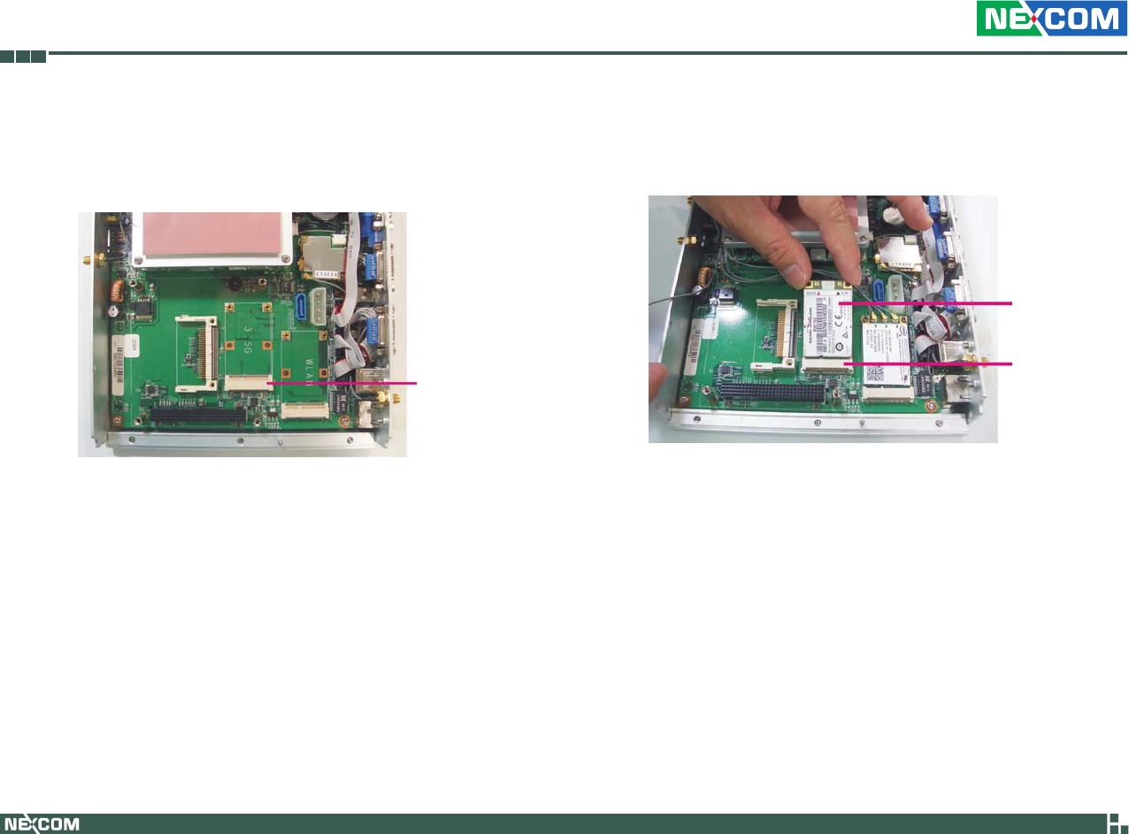
Installing a GPRS/UMTS/HSDPA Module
1. The Mini PCI Express slot shown below is used to install a 3.5G com-
munication module such as GPRS, UMTS or HSDPA module.
2. Insert the module into the Mini PCI Express slot at a 45 degrees angle
until the gold-plated connector on the edge of the module completely
disappears inside the slot.
Mini PCI
Express slot
GPRS/UMTS/
HSDPA module
Mini PCI
Express slot

Copyright © 2009 NEXCOM International Co., Ltd. All Rights Reserved. 40
Chapter 3: System Setup
VTC 6110 User Manual
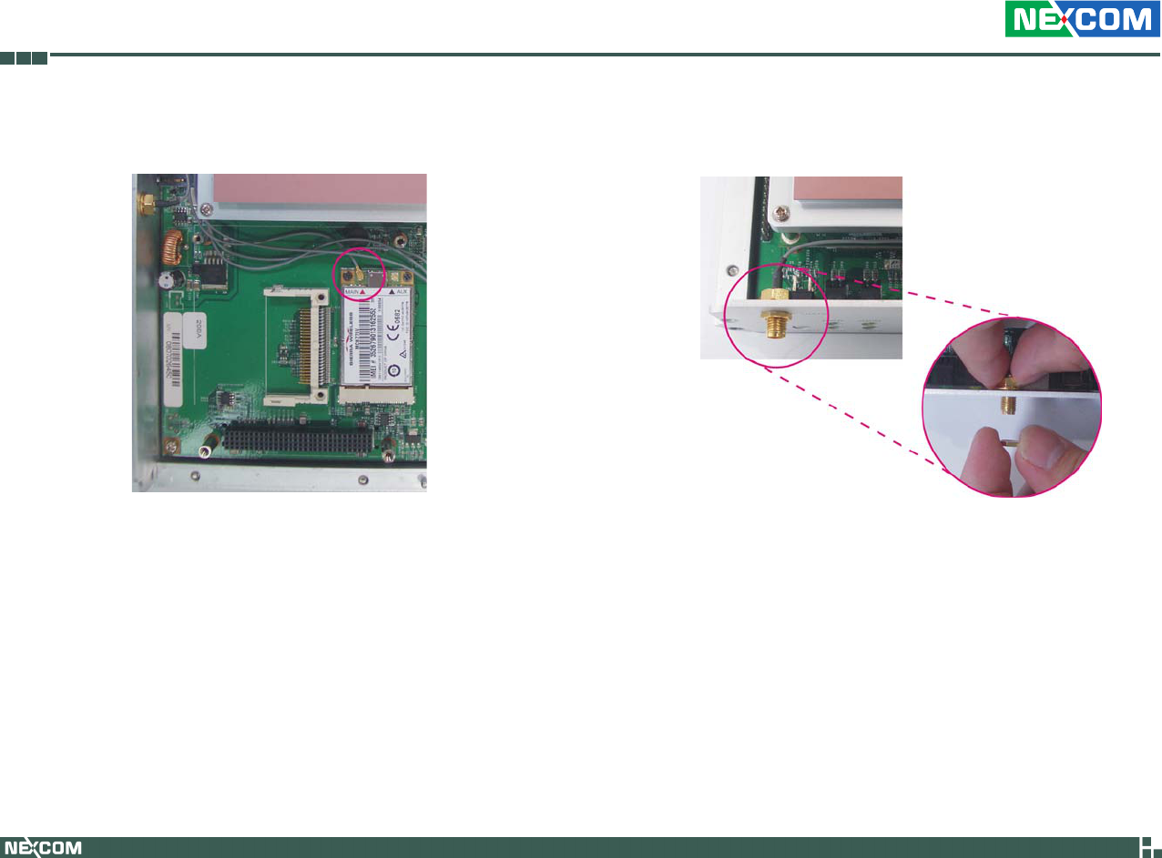
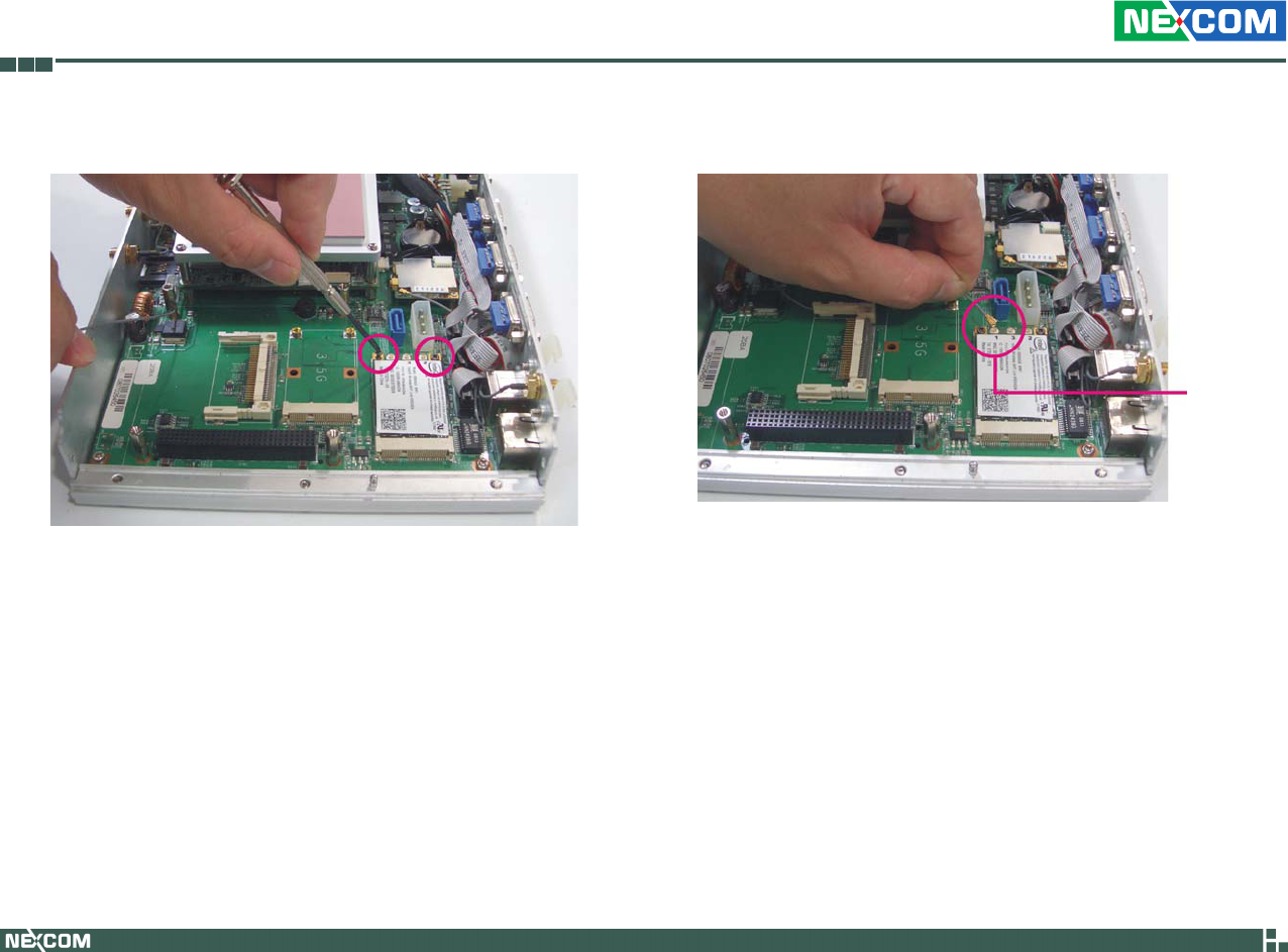
3. Push the module down then secure it with mounting screws. 4. Attach one end of the RF cable onto the module.
Attach RF cable
to the module
Copyright © 2009 NEXCOM International Co., Ltd. All Rights Reserved. 41
Chapter 3: System Setup
VTC 6110 User Manual
6. Mount the other end of the cable to the antenna mounting hole lo-
cated at the front panel of the chassis.
5. The photo below shows one end of the RF cable properly attached
onto the module.
RF cable mounted
at the front panel
Copyright © 2009 NEXCOM International Co., Ltd. All Rights Reserved. 42
Chapter 3: System Setup
VTC 6110 User Manual
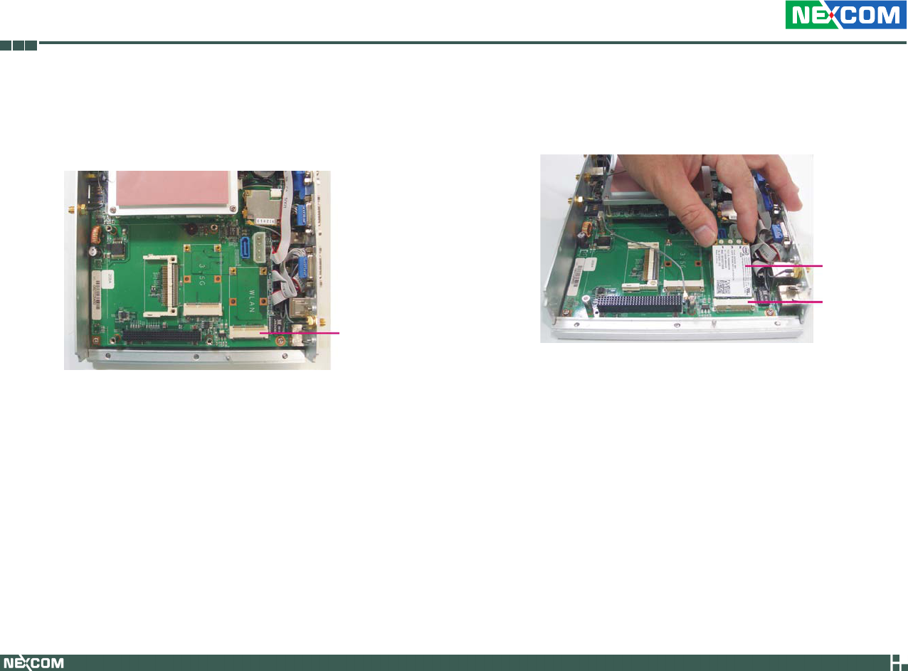
Installing a Wireless LAN Module
1. The Mini PCI Express slot shown below is used to install a wireless LAN
module.
Mini PCI
Express slot
2. Insert the wireless LAN module into the Mini PCI Express slot at a 45
degrees angle until the gold-plated connector on the edge of the mod-
ule completely disappears inside the slot.
Wireless LAN
module
Mini PCI
Express slot
Copyright © 2009 NEXCOM International Co., Ltd. All Rights Reserved. 43
Chapter 3: System Setup
VTC 6110 User Manual
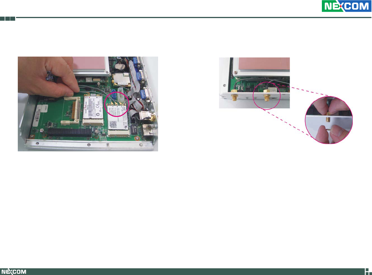
4. Attach one end of the RF cable onto the module.
Attach RF
cable to the
module
3. Push the module down then secure it with mounting screws.
Copyright © 2009 NEXCOM International Co., Ltd. All Rights Reserved. 44
Chapter 3: System Setup
VTC 6110 User Manual
5. The photo below shows one end of the RF cable properly attached
onto the module.
6. Mount the other end of the cable to the antenna mounting hole lo-
cated at the front panel of the chassis.
RF cable mounted
at the front panel
Copyright © 2009 NEXCOM International Co., Ltd. All Rights Reserved. 45
Chapter 3: System Setup
VTC 6110 User Manual
Installing a Bluetooth Module
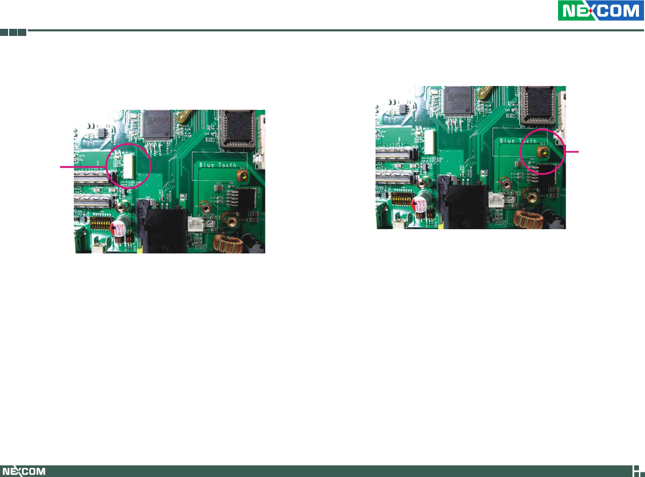
1. The USB header shown below is used to install a Bluetooth module.
USB
header
2. Install the provided mounting stud as shown in the illustration below.
Mounting
stud
Copyright © 2009 NEXCOM International Co., Ltd. All Rights Reserved. 46
Chapter 3: System Setup
VTC 6110 User Manual
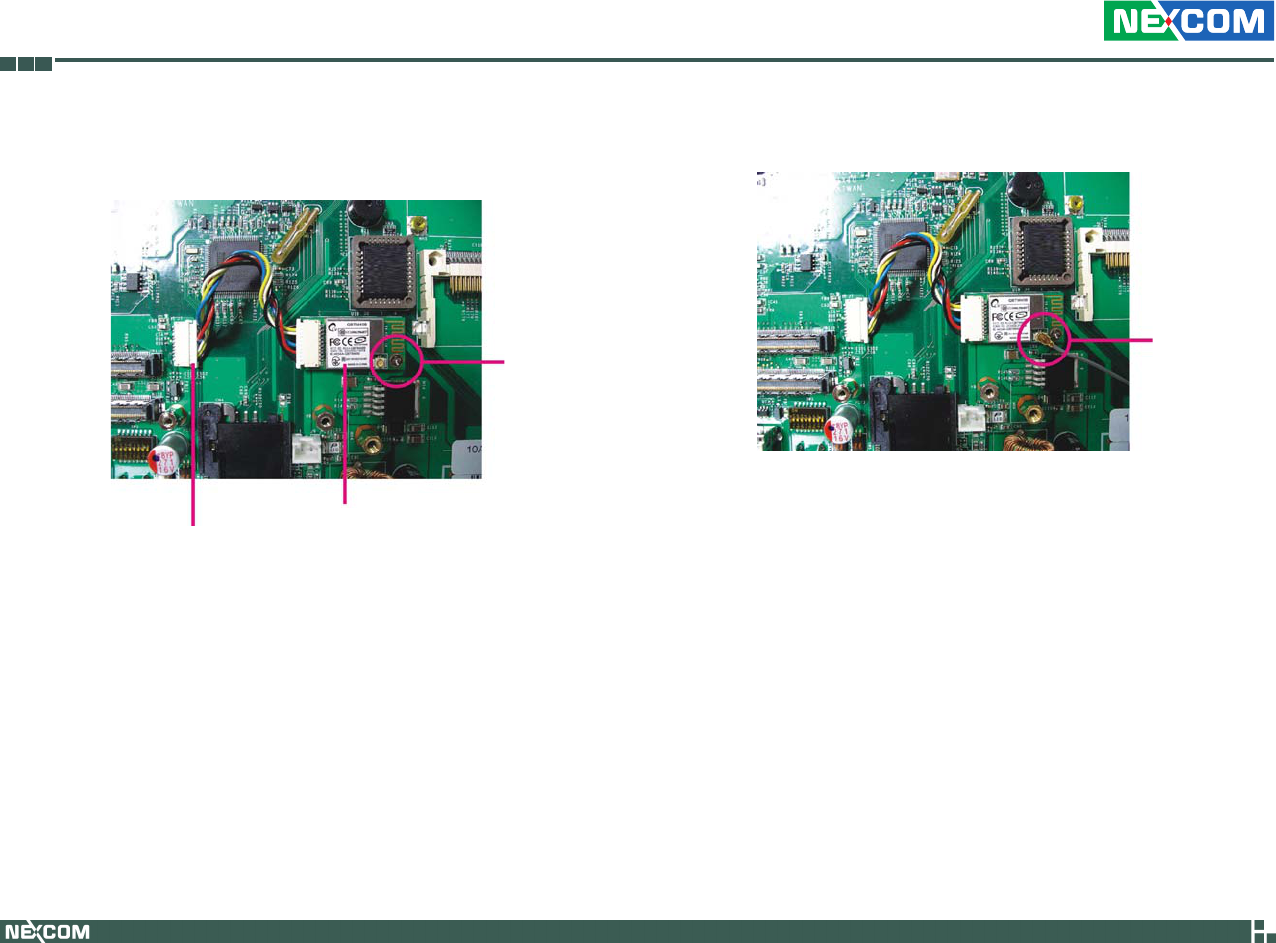
3. Insert the Bluetooth module’s cable connector into the USB header.
Push the module down then secure it with a mounting screw.
Bluetooth module
Cable connector
Mounting
screw
4. Attach one end of the RF cable onto the module.
Attach RF
cable to the
module
5. Mount the other end of the cable to the Bluetooth mounting hole
located at the front panel of the chassis.
Copyright © 2009 NEXCOM International Co., Ltd. All Rights Reserved. 47
Chapter 3: System Setup
VTC 6110 User Manual
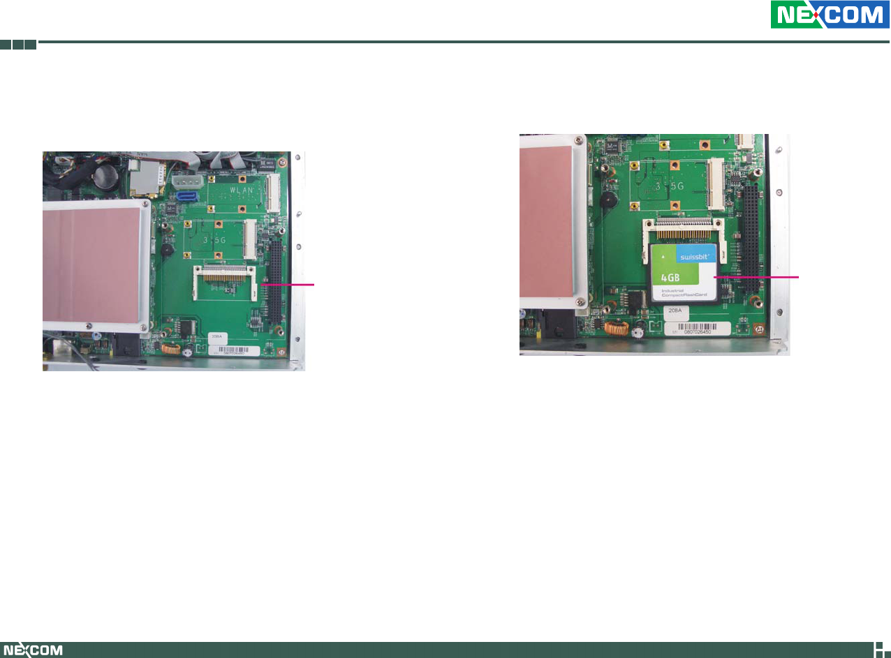
Installing a CompactFlash Card
1. Locate for the CompactFlash socket on the board.
2. With the CompactFlash card’s label facing up, position the card to the
socket.
CompactFlash
socket
CompactFlash
card
Copyright © 2009 NEXCOM International Co., Ltd. All Rights Reserved. 48
Chapter 3: System Setup
VTC 6110 User Manual
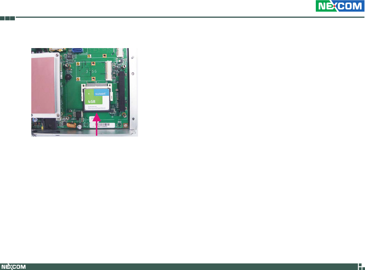
3. Insert the card until it is completely seated in the socket.
Copyright © 2009 NEXCOM International Co., Ltd. All Rights Reserved. 49
Chapter 3: System Setup
VTC 6110 User Manual
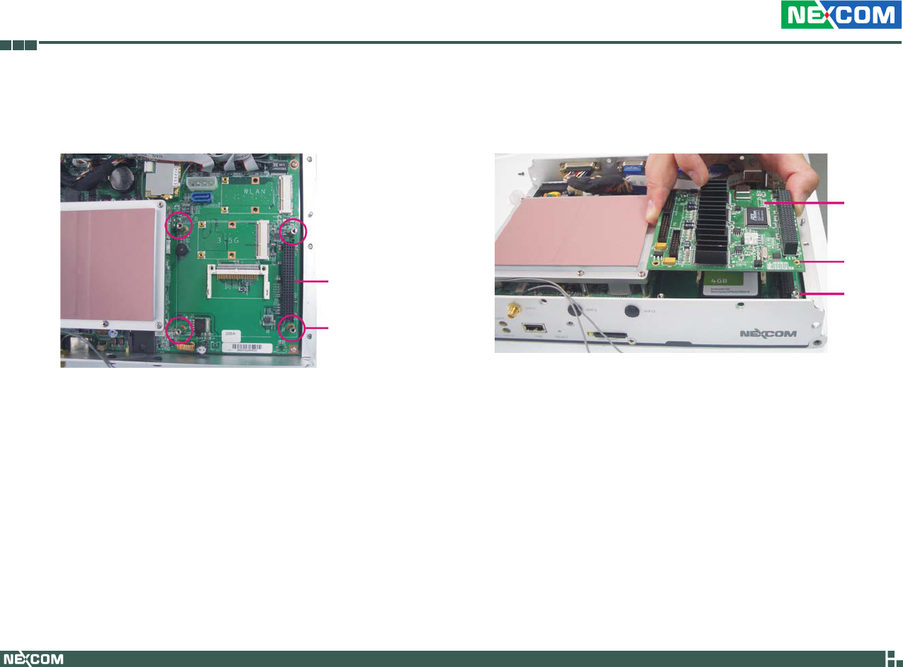
Installing the PCI-104 Module
1. Locate for the PCI-104 slot on the board.
PCI-104 slot
Mounting stud
2. Position the PCI-104 module above the slot then press it down firmly
until it is completely seated in the slot. This will at the same time align
the module’s mounting holes to the mounting studs on the board.
Mounting
stud
Mounting
hole
PCI-104
module
Copyright © 2009 NEXCOM International Co., Ltd. All Rights Reserved. 50
Chapter 3: System Setup
VTC 6110 User Manual
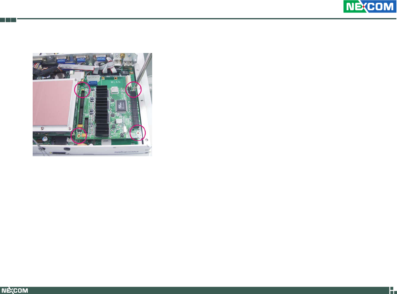
3. Secure the module with mounting screws.
Copyright © 2009 NEXCOM International Co., Ltd. All Rights Reserved. 51
Chapter 3: System Setup
VTC 6110 User Manual
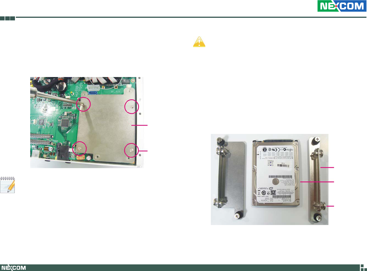
Installing a SATA Hard Drive
The metal bracket is used to hold a SATA hard drive. First, remove the 1.
screws that secure the metal bracket to the board then remove the
bracket.
If you intend to install a CompactFlash card or a Mini PCI Express
module, please install these devices first before proceeding to the
next step. Refer to their respective sections in this chapter for in-
structions on installing a CF card or a Mini PCI Express module.
2. Position the HDD brackets on each side of the SATA drive. Align the
mounting holes that are on the sides of the SATA drive with the HDD
brackets’ mounting screws.
HDD bracket
SATA drive
Mounting
screws
Metal
bracket
Mounting
screws
During Windows XP OS installation, press “F6” to select and •
install the SATA driver.
If you intend to install a Windows XP SP2 or earlier version, you •
must first set the “USB 2.0 Controller” field (in the BIOS) to
Disabled.
By default, the “Legacy USB Support” field (in the BIOS) is •
Disabled. If you are using a USB device to install the Windows
operating system, you must first set this field to Enabled. Set this
field back to Disabled after you have finished the installation.
Copyright © 2009 NEXCOM International Co., Ltd. All Rights Reserved. 52
Chapter 3: System Setup
VTC 6110 User Manual
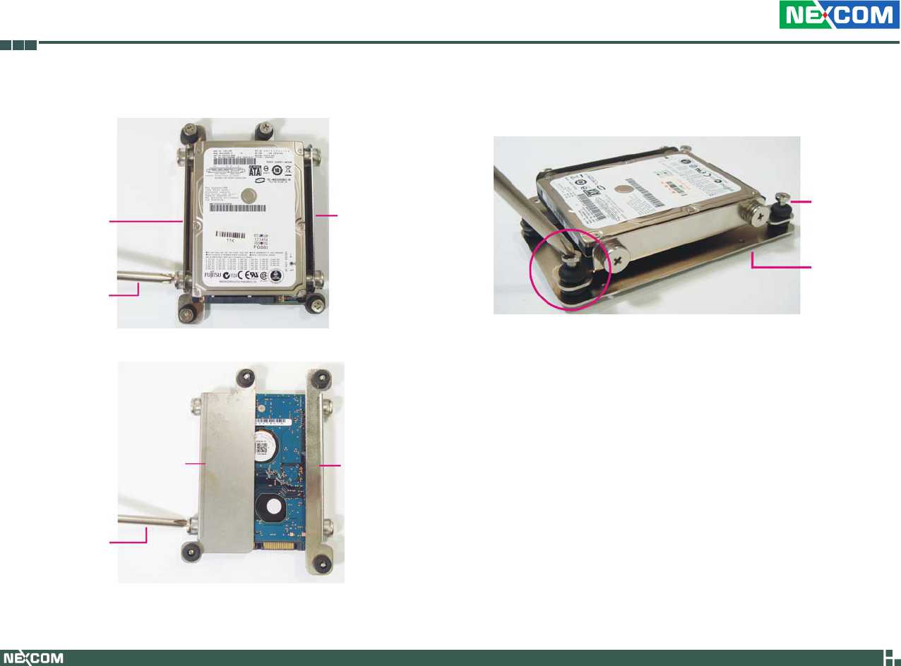
Screwdriver
3. Tighten the mounting screws to secure the HDD brackets in place.
HDD bracket HDD bracket
Screwdriver
HDD bracket HDD bracket
Top View
Bottom View
4. Now place the SATA drive on the metal bracket then tighten the head
bolt screws to secure the drive on the metal bracket.
Metal bracket
Head bolt screw
Copyright © 2009 NEXCOM International Co., Ltd. All Rights Reserved. 53
Chapter 3: System Setup
VTC 6110 User Manual
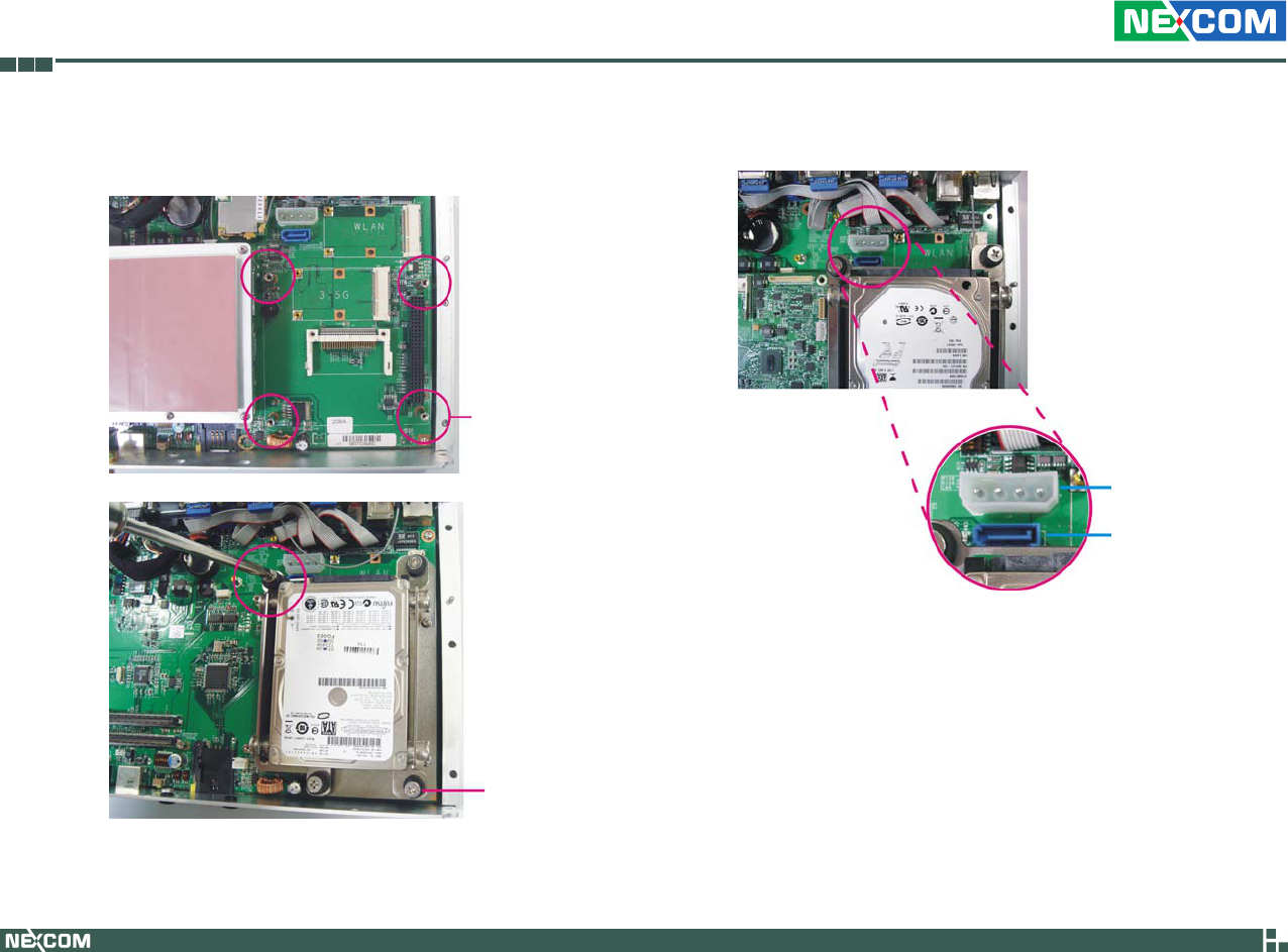
5. Align the head bolt screws with the mounting studs on the board.
Tighten the head bolt screws to secure the drive to the chassis.
Mounting stud
Head bolt screw
6. Locate for the SATA connector and the power connector. on the board.
SATA connector
Power connector

Copyright © 2009 NEXCOM International Co., Ltd. All Rights Reserved. 54
Chapter 3: System Setup
VTC 6110 User Manual
7. Connect one end of the SATA data cable to the SATA connector that is
on the board then connect the other end of the cable to the SATA con-
nector at the rear of the SATA drive.
SATA data cable
Cable connected
to the SATA drive
Cable connected to
the SATA connector
on the board
8. Connect one end of the SATA power cable to the SATA power connec-
tor that is on the board then connect the other end of the cable to the
SATA power connector at the rear of the SATA drive.
SATA power cable
Cable connected
to the SATA drive
Cable connected to the
SATA power connector
on the board
Copyright © 2009 NEXCOM International Co., Ltd. All Rights Reserved. 55
Chapter 3: System Setup
VTC 6110 User Manual
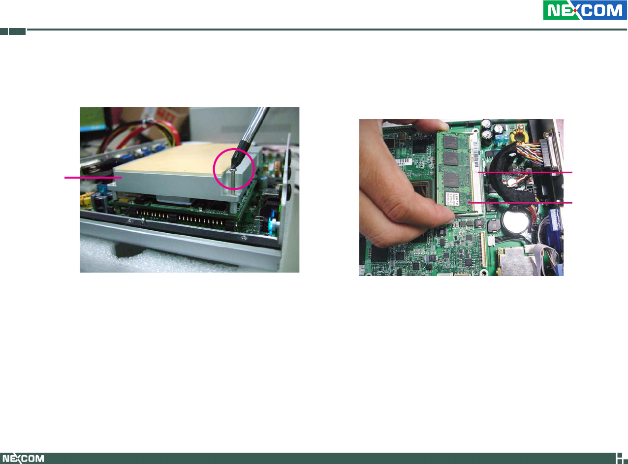
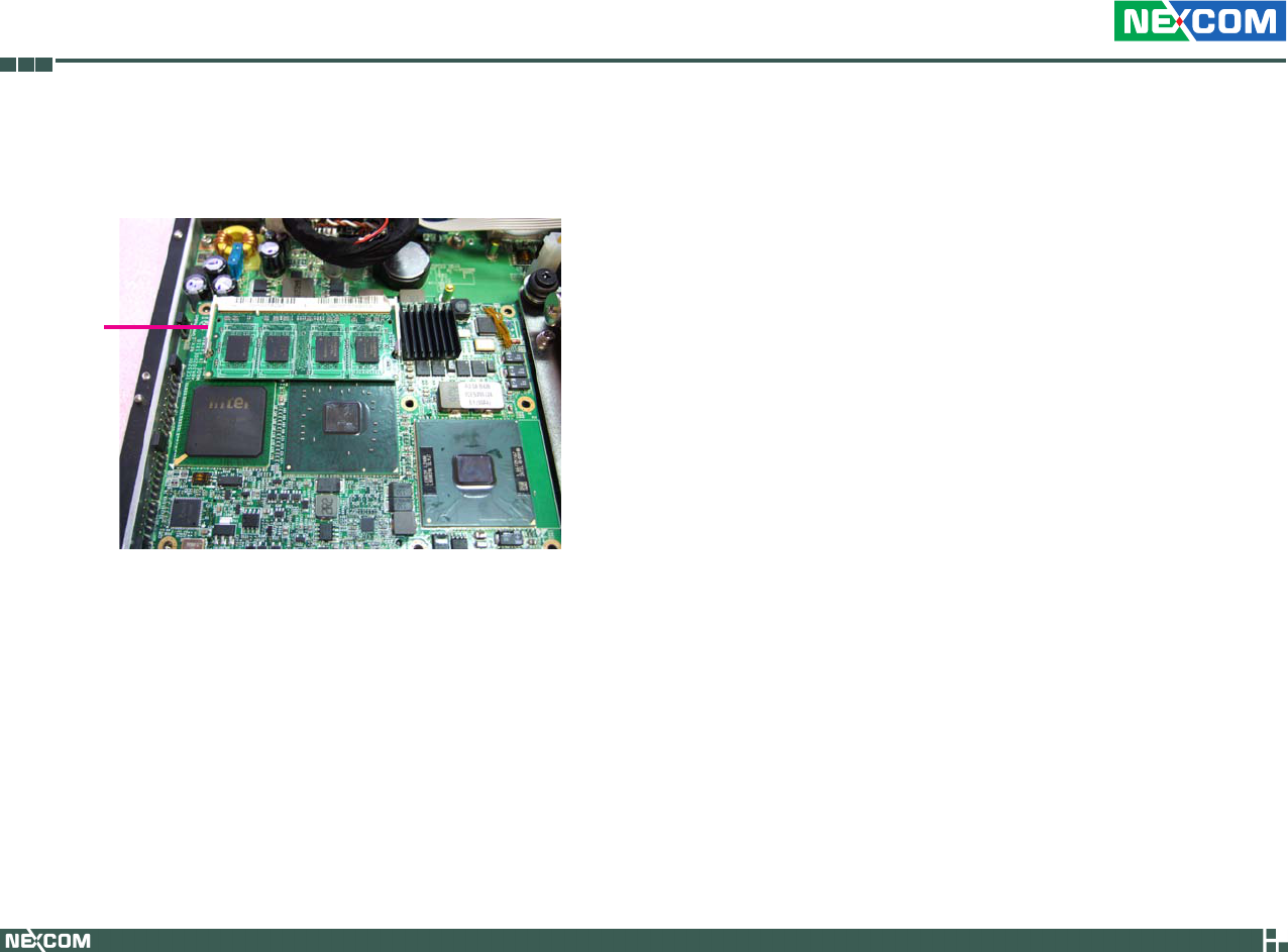
Installing the SODIMM
Remove the heatspreader’s mounting screws.1.
Heatspreader
2. Insert the module into the socket at an approximately 30 degrees
angle. Apply firm even pressure to each end of the module until it slips
into the socket. The gold-plated connector on the edge of the module
will almost completely disappear inside the socket.
SODIMM
socket
SODIMM
Copyright © 2009 NEXCOM International Co., Ltd. All Rights Reserved. 56
Chapter 3: System Setup
VTC 6110 User Manual
3. Push the module down until the clips on both sides of the socket lock
into position. You will hear a distinctive “click”, indicating the module
is correctly locked into position.
Clip