NEXTECH TE315M TPMS Exciter User Manual TPMS GENE
NEXTECH CO., LTD. TPMS Exciter TPMS GENE
UserManual.wiki
>
NEXTECH
>
TE315M User Manual
User Manual
Navigation menu
Upload a User Manual
Namespaces
Wiki Guide
HTML
PDF
Info
Views
User Manual
Discussion / Help
Navigation
![PROLOGUE OPERATION GUIDE 5 UNPACKING The TPMS EXCITER kit comprises the following standard along with the option kit where ordered. The kit contents should be checked upon receipt and damage or shortages reported to the supplier immediately. [ Figure 0.1 : TPMS EXCITER KIT ]](https://usermanual.wiki/NEXTECH/TE315M/User-Guide-549921-Page-5.png)

![GENERAL INFORMATION OPERATION GUIDE I-43. TPMS EXCITER Parts Description (1) TPMS EXCITER MAIN BODY (Part No: 09900-33000) The TPMS EXCITER main body is illustrated in figure I.1. [Figure I.1: TPMS EXCITER MAIN BODY]](https://usermanual.wiki/NEXTECH/TE315M/User-Guide-549921-Page-11.png)
![GENERAL INFORMATION OPERATION GUIDE I-5 (2) DLC CABLE 16 (Part no: 09900-33030) The cable is illustrated in figure I.2 and is used to connect the main body to the diagnosis terminal of vehicles with 16 pin connector vehicles. [Figure I.2: DLC CABLE 16]](https://usermanual.wiki/NEXTECH/TE315M/User-Guide-549921-Page-12.png)
![GENERAL INFORMATION OPERATION GUIDE I-6(3) CARRYING CASE (Part no: 09900-33080) The carrying case illustrated in figure I.3 provides for easy transportation of TPMS EXCITER and protection for the unit when not in use. [Figure I.3: CARRYING CASE]](https://usermanual.wiki/NEXTECH/TE315M/User-Guide-549921-Page-13.png)
![GENERAL INFORMATION OPERATION GUIDE I-7(4) USB CABLE (Part no: 09900-33040) The cable is illustrated in figure 1.4 and interfaces between the TPMS EXCITER main body and PC when S/W download. [Figure I.4: USB CABLE]](https://usermanual.wiki/NEXTECH/TE315M/User-Guide-549921-Page-14.png)
![GENERAL INFORMATION OPERATION GUIDE I-8 (5) OPERATION MANUAL (Part no: 09900-33060) The guide, illustrated in figure 1.6 provides TPMS EXCITER user Instruction. [Figure I.5: OPERATION MANUAL]](https://usermanual.wiki/NEXTECH/TE315M/User-Guide-549921-Page-15.png)
![GENERAL INFORMATION OPERATION GUIDE I-9 (6) RUBBER SHROUD (Part no: 09900-33010) The rubber shroud is used to protect the main body from damage when in use. [Figure I.6: RUBBER SHROUD]](https://usermanual.wiki/NEXTECH/TE315M/User-Guide-549921-Page-16.png)
![GENERAL INFORMATION OPERATION GUIDE I-10(7) S/W DOWNLOAD CD (Part no: 09900-33070) The S/W DOWNLOAD CD is used to install the S/W DOWNLOAD program. [ Figure I.7 : S/W DOWNLOAD CD]](https://usermanual.wiki/NEXTECH/TE315M/User-Guide-549921-Page-17.png)
![GENERAL INFORMATION OPERATION GUIDE I-11(8) AC/DC ADAPTOR(12V 3A) (Part no : 09900-33050) The AC/DC ADAPTOR provides power to the TPMS EXCITER when updating the software with the S/W DOWNLOAD ADAPTOR. [ Figure I.8 : AC/DC ADAPTOR]](https://usermanual.wiki/NEXTECH/TE315M/User-Guide-549921-Page-18.png)
![TPMS DIAGNOSIS OPERATION GUIDE II-32. VEHICLES AND SYSTEM SELECTION 2-1. OPERATION FLOW INITIAL MENU TPMS DIAGNOSIS HYUNDAI/KIA VEHICLE DIAGNOSIS [FLOW II.1: VEHICLE AND SYSTEM SELECTION SUB-MENU IN/OUT]](https://usermanual.wiki/NEXTECH/TE315M/User-Guide-549921-Page-21.png)
![TPMS DIAGNOSIS OPERATION GUIDE II-42-2. BASIC APPLICATION Having connected and turned on TPMS EXCITER, the vehicle and systems 1 and 2 selections must be made from the [ 1.0 VEHICLE DIAGNOSIS] screen. The support functions differ from vehicle to vehicle and therefore the correct selection must be made. Selection can be made by scrolling up or down the screen and pressing ENTER. Selection is made in the order of VEHICLE, SYSTEM 1, and SYSTEM 2.](https://usermanual.wiki/NEXTECH/TE315M/User-Guide-549921-Page-22.png)
![TPMS DIAGNOSIS OPERATION GUIDE II-53. DIAGNOSTIC TROUBLE CODES 3-1. OPERATION FLOW 01. INITIAL SCREEN VEHICLE AND SYSTEM SELECTION Refer to “Selecting Vehicle Mode” 0.X DIAGNOSTIC TROUBLE CODES ERAS 1.2.2 ERASE FAULT CODE [FLOW II.2: DIAGNOSTIC TROUBLE CODES IN/OUT FLOW]](https://usermanual.wiki/NEXTECH/TE315M/User-Guide-549921-Page-23.png)
![TPMS DIAGNOSIS OPERATION GUIDE II-74. CURRENT DATA 4-1. OPERATION FLOW 01. INTIAL SCREEN VEHICLE AND SYSTEM SELECTION Refer to “Selecting Vehicle Mode” 0.2 CURRENT DATA FIX 1.2.1 FIX ITEM FULL 1.2.2 DISPLAY ALL ITEMS GRPH 1.2.3 GRAPHICAL DISPLAY [FLOW II.3: CURRENT DATA MODE IN/OUT FLOW]](https://usermanual.wiki/NEXTECH/TE315M/User-Guide-549921-Page-25.png)
![TPMS DIAGNOSIS OPERATION GUIDE II-84-2. MODE APPLICATION The sensor values and the ON/OFF state of the system switches of the selected ECM are displayed. Scrolling up and down the data is possible by means of the UP / DOWN keys and more detailed data is available by Using the soft function keys as follows: FIX Executing the [FIX ITEM] function that moves the item in inverted text to the top of the display. This item is held and does not move when the cursor keys are used to page through the display and therefore allows specific items to be compared directly to one another. [Figure II.1: FIX ITEM]](https://usermanual.wiki/NEXTECH/TE315M/User-Guide-549921-Page-26.png)
![TPMS DIAGNOSIS OPERATION GUIDE II-9A fixed item may be released by depressing the FIX key again. In the example, illustrated by [figure II.1], is fixed as denoted by the asterisk to the left of the item number. FULL Use of this key will cause maximum 22 data value to be displayed on the screen as illustrated in [figure II.2] The component description displayed will be abbreviated when this mode is used. The date may be scrolled by use of the UP / DOWN key. [Figure II.2: DISPLAY ALL ITEMS]](https://usermanual.wiki/NEXTECH/TE315M/User-Guide-549921-Page-27.png)
![TPMS DIAGNOSIS OPERATION GUIDE II-10GRPH Where more 2 ‘active’ data items have been selected using the FIX key, pressing the GRPH key will cause the data for those items to be displayed in the form of a graph as illustrated in [figure II.3]. [Figure II.3: CURRENT DATA (GRPH)] FIX Holding one item of two. When the UP / DOWN keys are used to scroll up and down the display, the item selected by FIX key does not move.](https://usermanual.wiki/NEXTECH/TE315M/User-Guide-549921-Page-28.png)
![TPMS DIAGNOSIS OPERATION GUIDE II-115. WARNING STATE 5-1. OPERATION FLOW 0.1 INITIAL SCREEN VEHICLE AND SYSTEM SELECTION Refer to “Selecting Vehicle Mode” 0X. WARNING STATE FIX 1.2.1 FIX ITEM FULL 1.2.2 DISPLAY ALL ITEMS [ FLOW II.4 : WARNING STATE MODE IN/OUT FLOW ]](https://usermanual.wiki/NEXTECH/TE315M/User-Guide-549921-Page-29.png)
![TPMS DIAGNOSIS OPERATION GUIDE II-125-2. MODE APPLICATION The WARNING STATE displays the data values stored in the ECM at the point when the first DTC is detected. A typical screen display is illustrated at [figure II.4]. [ Figure II.4:WARNING STATE DATA ]](https://usermanual.wiki/NEXTECH/TE315M/User-Guide-549921-Page-30.png)
![TPMS DIAGNOSIS OPERATION GUIDE II-13FIX Executing the [FIX ITEM] function that moves the item in inverted text to the top of the display. This item is held and does not move when the cursor keys are used to page through the display and therefore allows specific items to be compared directly to one another. [Figure II.5: FIX ITEM] A fixed item may be released by depressing the FIX key again. In the example, illustrated by [figure II.5], is fixed as denoted by the asterisk to the left of the item number. FULL Use of this key will cause maximum 22 data value to be displayed on the screen as illustrated in [figure II.6]. The component description displayed will be abbreviated when this mode is used. The date may be scrolled by use of the UP / DOWN key.](https://usermanual.wiki/NEXTECH/TE315M/User-Guide-549921-Page-31.png)
![TPMS DIAGNOSIS OPERATION GUIDE II-14 [Figure II.6: DISPLAY ALL ITEMS]](https://usermanual.wiki/NEXTECH/TE315M/User-Guide-549921-Page-32.png)
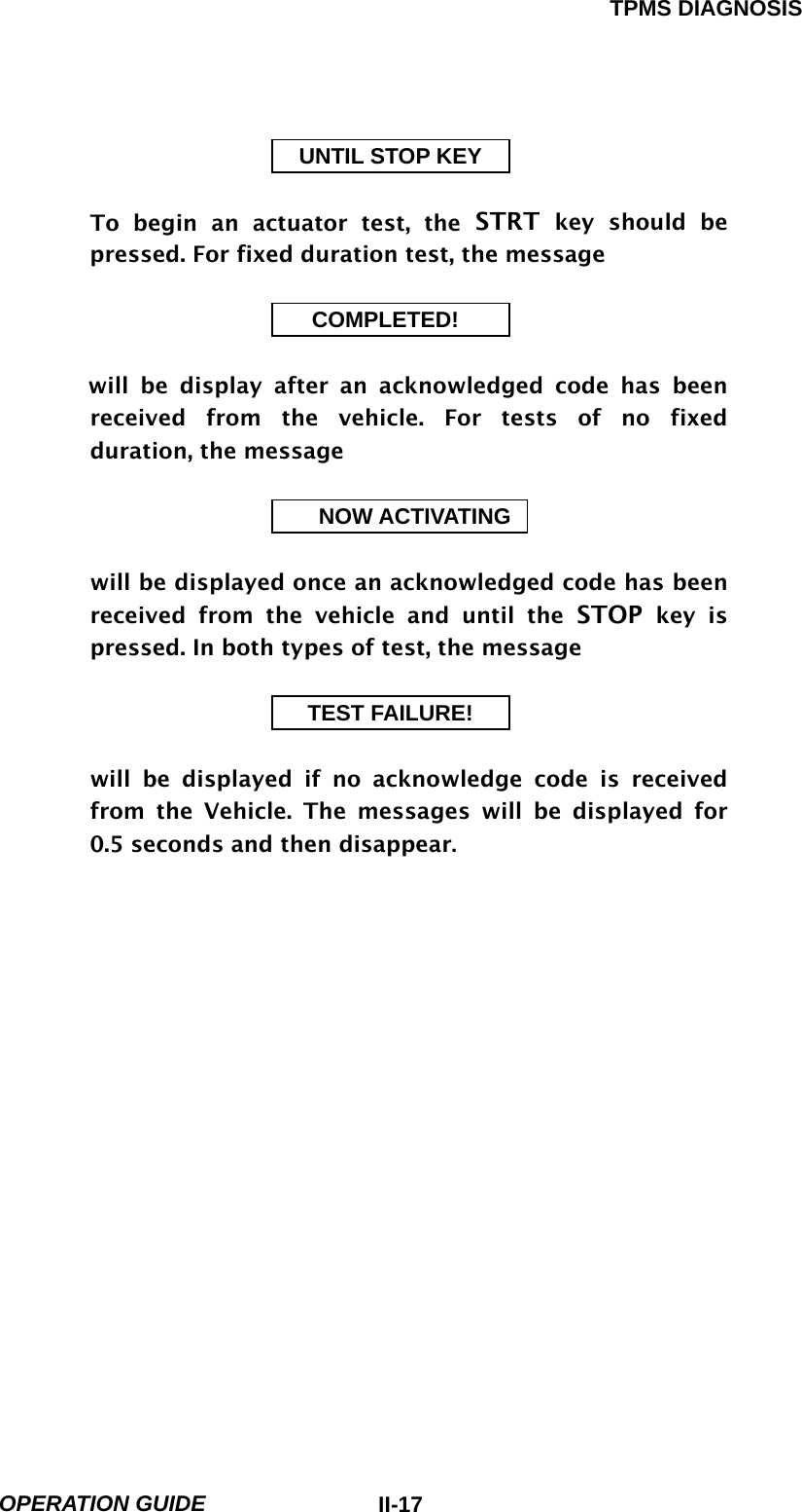
![TPMS DIAGNOSIS OPERATION GUIDE II-156. ACTUATION TEST 6-1 OPERATION FLOW 0.1 INITIAL SCREEN VEHICLE AND SYSTEM SELECTION Refer to “Selecting Vehicle Mode” 0X. ACTUATION TEST START START ACTIVATING [FLOW II.5: ACTUATION TEST MODE IN/OUT FLOW]](https://usermanual.wiki/NEXTECH/TE315M/User-Guide-549921-Page-33.png)
![TPMS DIAGNOSIS OPERATION GUIDE II-166-2 MODE APPLICATION The ACTUATION TEST mode allows certain actuators to be forcibly driven by TPMS EXCITER but this mode can only be supported according to the selected vehicle. The illustration of a typical screen is shown in [figure II.7]. The actuator to be driven can be changed by using the UP / DOWN key to scroll through the list. [Figure II.7: ACTUATOR DRIVING] The test must be performed with the vehicle in the state indicated by the CONDITION statement on the screen. In this illustration given, for example, the ignition key must be turned “on”, and the engine must be running. The duration of the test will either be fixed by TPMS EXCITER and indicated on the screen or the duration dialogue will be indicated.](https://usermanual.wiki/NEXTECH/TE315M/User-Guide-549921-Page-34.png)
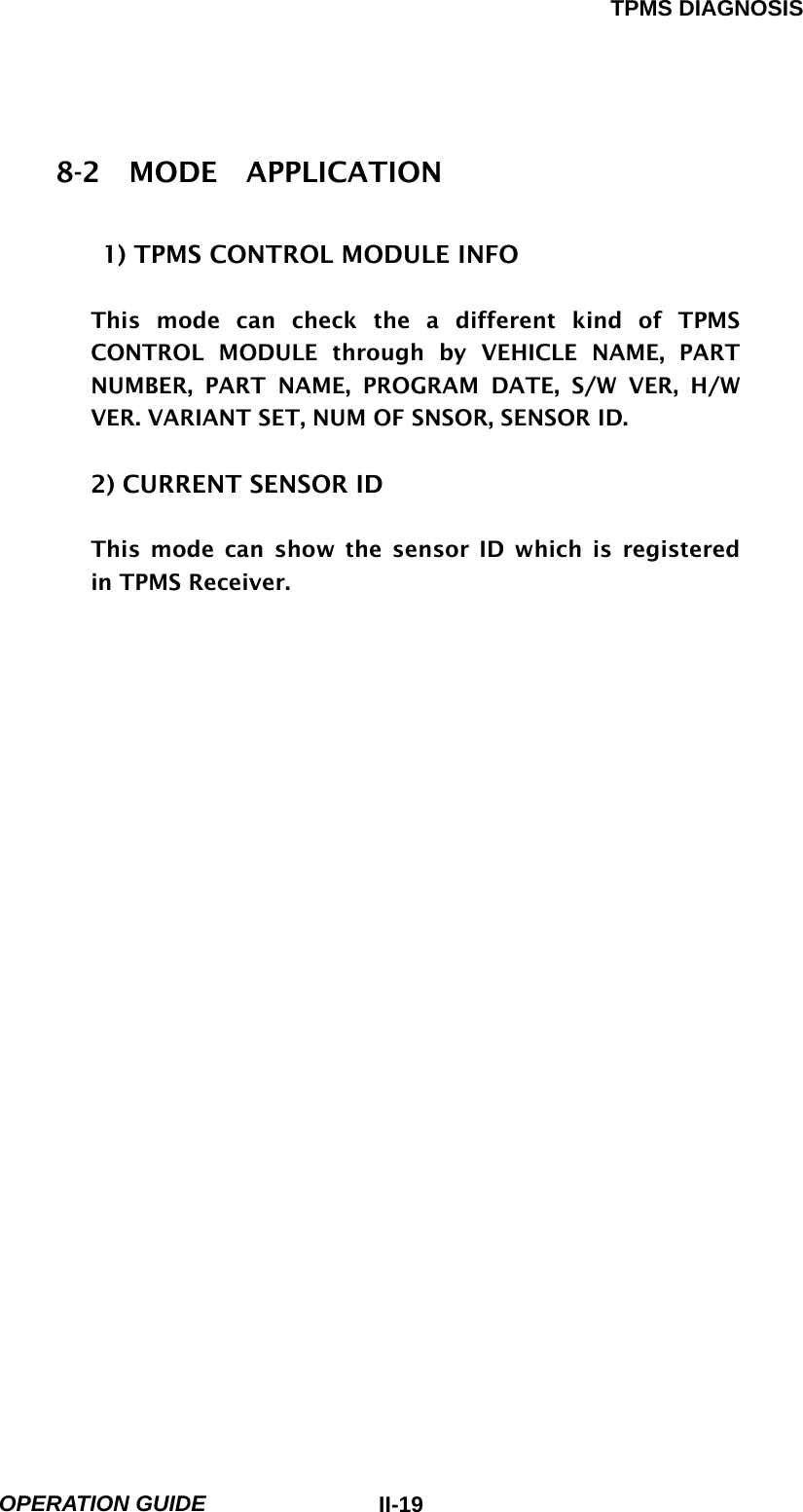
![TPMS DIAGNOSIS OPERATION GUIDE II-187. ECU INFORMATION 7-1. OPERATION FLOW 01.INITIAL SCREEN VEHICLE AND SYSTEM SELECTION Refer to “Selecting Vehicle Mode” 0X. ECU INFORMATION 01. TPMS CONTROL MODULE INFO 02.CURRENT SENSOR ID [FLOW II.6: ECU INFOR. MODE IN/OUT FLOW]](https://usermanual.wiki/NEXTECH/TE315M/User-Guide-549921-Page-36.png)
![TPMS DIAGNOSIS OPERATION GUIDE II-208. SPECIFIC DATA WRITING 8-1. OPERATION FLOW 0.1 INITIAL SCREEN VEHICLE AND SYSTEM SELECTION Refer to “Selecting Vehicle Mode” 0X. ECU INFORMATION [FLOW II.7: SPECIFIC DATA WRITING MODE IN/OUT FLOW]](https://usermanual.wiki/NEXTECH/TE315M/User-Guide-549921-Page-38.png)
![TPMS DIAGNOSIS OPERATION GUIDE II-218-2 MODE APPLICATION This mode can register the sensor ID when be changed the TPMS Receiver or sensors. 01 01. VEHICLE NAME [Figure II.8 : VEHICLE NAME ] This function is to input vehicle name chapter to TPMS CONTROL MODULE. You must input vehicle name correctly otherwise TPMS system may not operate normally. 1. Change value : [UP ] , [DOWN] key 2. Cursor move : [ LEFT ] , [RIGHT] key 3. Write data : [ ENTER ] key](https://usermanual.wiki/NEXTECH/TE315M/User-Guide-549921-Page-39.png)
![TPMS DIAGNOSIS OPERATION GUIDE II-22 02 02. WHEEL SENSOR ID [Figure II.9 : SENSOR ID DATA ] This function is to input sensor ID to TPMS CONTROL MODULE, Which is used to operate the TPMS system properly the data is composed of 8 characters in ARABIC number and ALPHABET. [CURRENT ID] is current setting sensor ID [CHANGE ID] is new writing sensor ID 1. Change value : [UP ], [DOWN] key ALPHABET value : [F1] ~ [F6] key ARABIC NUMBER : [0] ~ [9] key 2. Cursor move to left : [LEFT] key Cursor move to right : [RIGHT] key Cursor move to up : [ LEFT ] + [UP ] KEY Cursor move to down : [ LEFT ] + [DOWN] KEY 3. Write the value : [ ENTER ]](https://usermanual.wiki/NEXTECH/TE315M/User-Guide-549921-Page-40.png)
![TPMS DIAGNOSIS OPERATION GUIDE II-23 03 03. VIN [Figure II.10 : VIN] This function is to change the TPMS CONTROL MODULE’S MODE. Can read the vehicle VIN number and can write the vehicle VIN number. 1. Change value : [UP ], [DOWN] KEY 2. Cursor move : [ LEFT ], [RIGHT] KEY 3. Write data : [ ENTER ] KEY](https://usermanual.wiki/NEXTECH/TE315M/User-Guide-549921-Page-41.png)
![TPMS DIAGNOSIS OPERATION GUIDE II-24 04 04. MODE CONFIGURATION [Figure II.11 : VEHICLE NAME ] This function is to change the TPMS CONTROL MODULE’S MODE. Write the sensor IDs, vehicle name and finally change the normal mode. 1. Change : [UP ], [DOWN] key 2. Writing : [ENTER] key](https://usermanual.wiki/NEXTECH/TE315M/User-Guide-549921-Page-42.png)
![TPMS DIAGNOSIS OPERATION GUIDE II-259. DUAL DISPLAY 9-1. OPERATION FLOW 0.2 INITIAL SCREEN VEHICLE AND SYSTEM SELECTION Refer to “Selecting Vehicle Mode” 0X. DUAL DISPALYS FIX FIX ITEM CURR CURRENT DATA DTC DIAG. TROUBLE CODES [ FLOW I1.8 : DUAL DISPLAY MODE IN/OUT FOLW ]](https://usermanual.wiki/NEXTECH/TE315M/User-Guide-549921-Page-43.png)
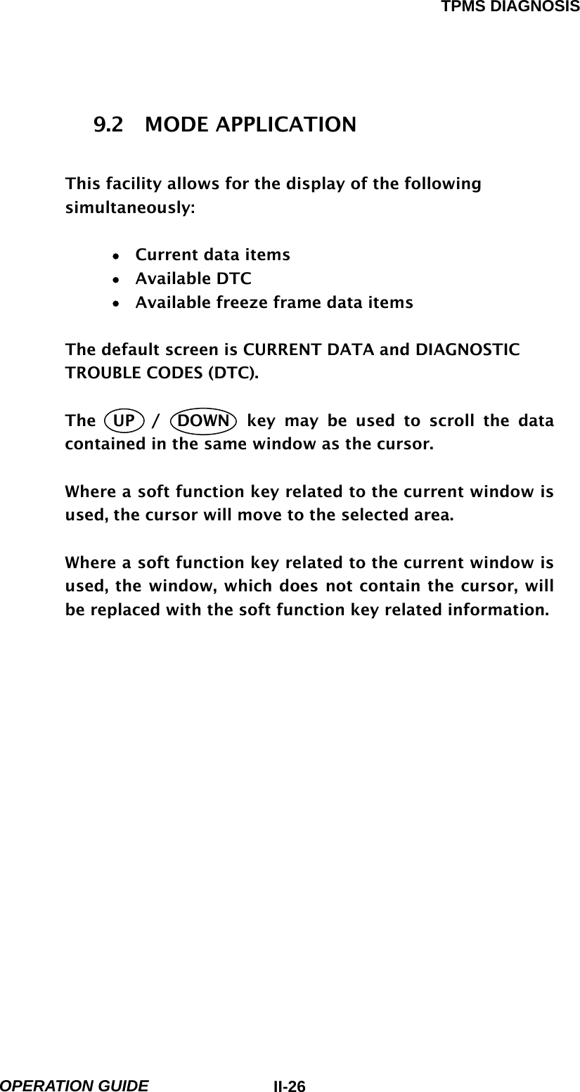
![TPMS DIAGNOSIS OPERATION GUIDE II-27A typical COMBINATION DISPLAY screen is illustrated at figure IV.14. [ Figure IV.14 : COMBINATION DISPLAY ] The UP / DOWN key is used to scroll through the display. FIX Holding one item of two. When the UP / DOWN keys are used to scroll up and down the display, the item selected by FIX key does not move. CURR Taking the cursor to the CURRENT DATA AREA. If the CURRENT DATA is being displayed, the CURR key will Move the cursor to that window. If the CURRENT DATA is not Being displayed, the window not containing the cursor will Be replaced with the CURRENT DATA display. DTC DIAGNOSTIC TROUBLE CODES Work in a similar manner to CURR except that the screen replaced is that selected by the soft function key description.](https://usermanual.wiki/NEXTECH/TE315M/User-Guide-549921-Page-45.png)

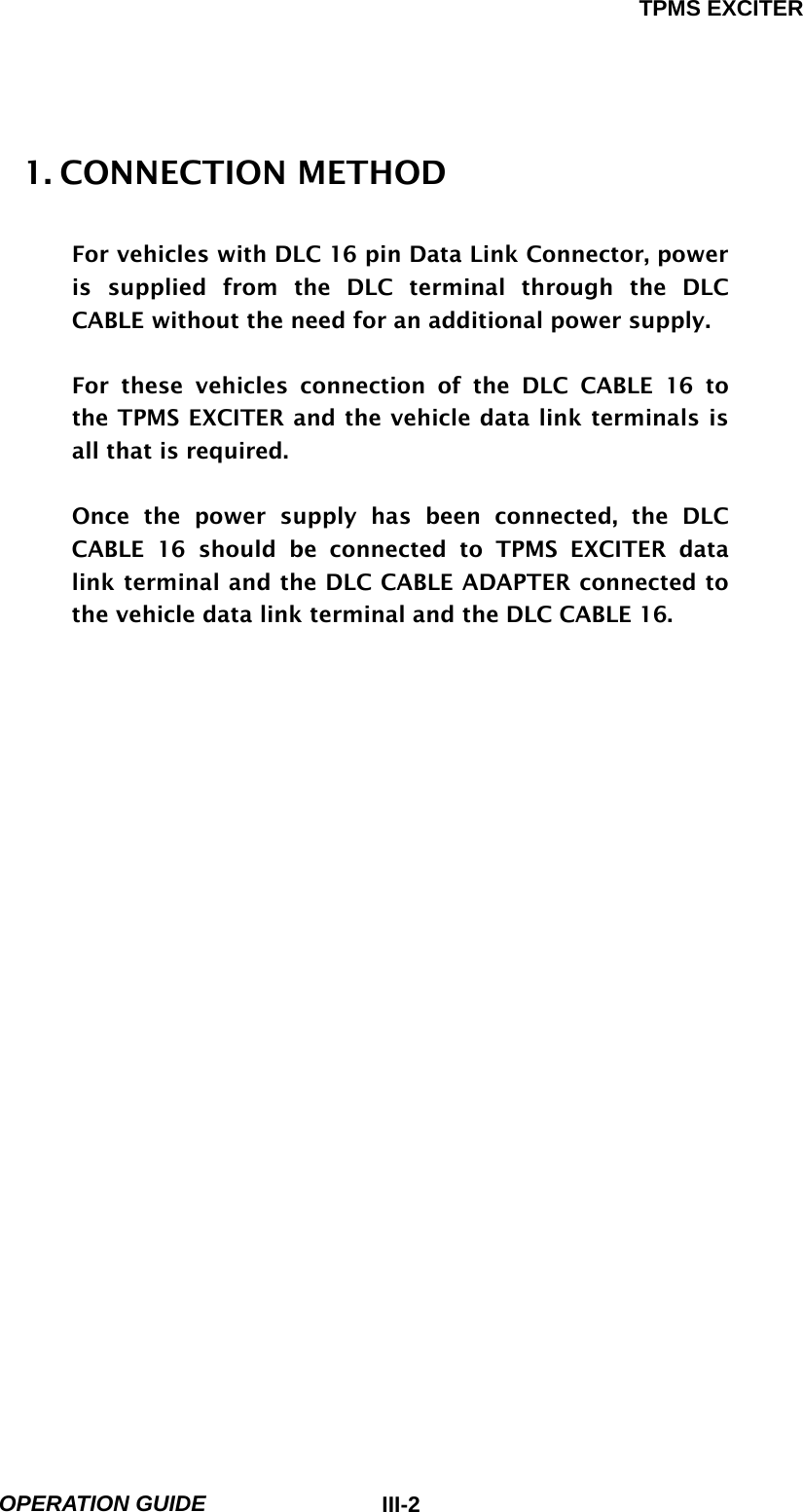
![TPMS EXCITER OPERATION GUIDE III-32. TPMS EXCITER 2-1. OPERATION FLOW 0.1 INITIAL SCREEN VEHICLE AND SYSTEM SELECTION Refer to “Selecting Vehicle Mode” 02. TPMS EXCITER [ FLOW III.1 : TPMS EXCITER MODE IN/OUT FLOW ]](https://usermanual.wiki/NEXTECH/TE315M/User-Guide-549921-Page-48.png)
![TPMS EXCITER OPERATION GUIDE III-41-2 MODE APPLICATION This mode can read the sensor IDs by RF communication and then can change sensor status, register the sensor to the TPMS CONTROL MODULE. 01 01.SET SENSOR STATUS [Figure III.1: SET SENSOR STATUS] PRESSURE : Display the NULL or real pressure of tire. This values will be changed by sensor option. TEMPERATURE : Display the NULL or real temperature of tire. This values will be changed by sensor option.](https://usermanual.wiki/NEXTECH/TE315M/User-Guide-549921-Page-49.png)
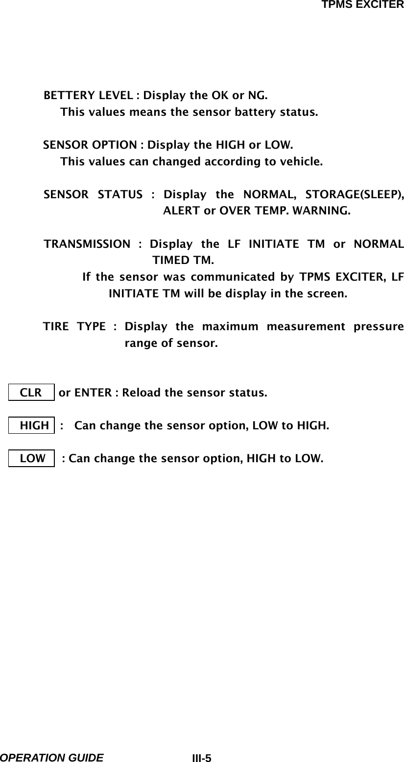
![TPMS EXCITER OPERATION GUIDE III-6 02 02.REGISTER SENSOR [Figure III.2: REGISTER SENSOR ] This mode can resister the sensor Ids to TPMS CONTROL MODULE after reading the sensor IDs of the each tires. CLR : Clear the screen. REG : can resister the sensor Ids to TPMS CONTROL MODULE with DLC cable. FL : Can reload the FL sensor ID. FR : Can reload the FR sensor ID. RL : Can reload the RL sensor ID. RR : Can reload the RR sensor ID.](https://usermanual.wiki/NEXTECH/TE315M/User-Guide-549921-Page-51.png)
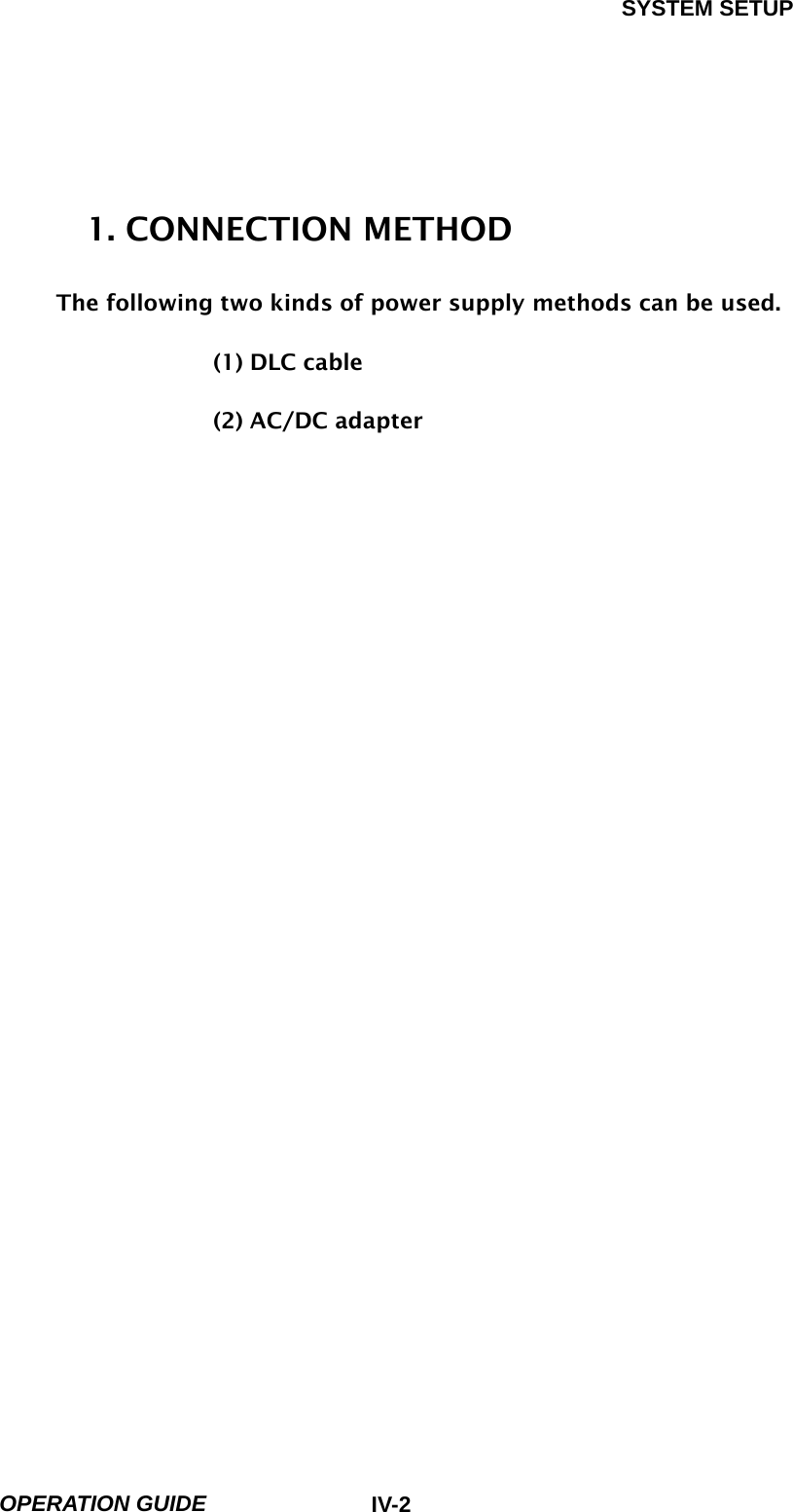
![SYSTEM SETUP OPERATION GUIDE IV-32. SYSTEM CONFIGURATION 2-1. OPERATION FLOW 0.1 INITIAL SCREEN X.0 SYSTEM SETUP 0.X SYSTEM CONFIGURATION [FLOW IV.1 : SYSTEM CONFIGURATION MODE IN/OUT FLOW]](https://usermanual.wiki/NEXTECH/TE315M/User-Guide-549921-Page-54.png)
![SYSTEM SETUP OPERATION GUIDE IV-53. DATA SETUP 3-1. OPERATION FLOW 0.1 INITIAL SCREEN X.0 SYSTEM SETUP 0.X DATA SETUP LEFT LEFT ITEM SELECTION RIGHT RIGHT ITEM SELECTION UP ITEM VALUE CHANGE + DOWN ITEM VALUE CHANGE- ENTER CONFIRM ITEM SELECTION [ FLOW IV.2 : DATA SETUP MODE IN/OUT FOLW ]](https://usermanual.wiki/NEXTECH/TE315M/User-Guide-549921-Page-56.png)
![SYSTEM SETUP OPERATION GUIDE IV-74. KEY PAD TEST 4-1. OPERATION FLOW 0.1 INITIAL SCREEN X.0 SYSTEM SETUP 0.X KEY PAD TEST [ FLOW IV.3 : KEY PAD TEST MODE IN/OUT FLOW ] 4-2. MODE APPLICATION User can perform TPMS EXCITER self-test.](https://usermanual.wiki/NEXTECH/TE315M/User-Guide-549921-Page-58.png)
![SYSTEM SETUP OPERATION GUIDE IV-85. CONTRAST ADJUST SCREEN 5-1. OPERATION FLOW 0.1 INITIAL SCREEN X.0 SYSTEM SETUP 0.X CONTRAST ADJUST SCREEN F2 SCREEN IS BRIGHTER F5 SCREEN IS DARKER [ FLOW IV.4 : CONTRAST ADJUST SCREEN ]](https://usermanual.wiki/NEXTECH/TE315M/User-Guide-549921-Page-59.png)
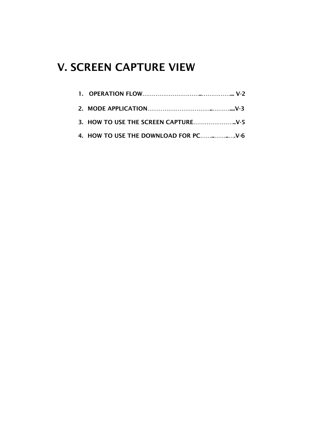
![SCREEN CAPTURE VIEW OPERATION GUIDE V-21. OPERATION FLOW 0.1 INITIAL SCREEN 0X. SCREEN CAPTURE VIEW ENTER ‘ [ FLOW V.1 : SCREEN CAPTURE IN FLOW ]](https://usermanual.wiki/NEXTECH/TE315M/User-Guide-549921-Page-62.png)
![SCREEN CAPTURE VIEW OPERATION GUIDE V-3 2. MODE APPLICATION TPMS EXCITER screen capture function can store 7-paged screen inside internal flash memory of TPMS EXCITER. In addition, when you see the relevant function, you can confirm through the SCREEN CAPTURE VIEW MENU of TPMS EXCITER initial screen or TPMS EXCITER download for PC. DEL This mode can delete the current screen. Press the F1 key If you want to delete the screen. A message will display to delete on the screen. The example screen is as follows: [Figure V.2 : Screen DELETE ] The current screen will be erased if you press ENTER. 01/07 The “01 “ is the current page number. The “07” is the saved total pages number.](https://usermanual.wiki/NEXTECH/TE315M/User-Guide-549921-Page-63.png)
![SCREEN CAPTURE VIEW OPERATION GUIDE V-4 ALL DEL This mode can delete the all captured screens. Press the F6 key If you want to delete the all screens. A message will display to delete on the screen. The example screen is as follows: [Figure V.3 : All screens DELETE ] The all captured screens will be erased if you press ENTER. If disconnected the battery pack to TPMS EXCITER, The all captured screens will be erased in the memory.](https://usermanual.wiki/NEXTECH/TE315M/User-Guide-549921-Page-64.png)
![SCREEN CAPTURE VIEW OPERATION GUIDE V-5 3. HOW TO USE THE SCREEN CAPTURE 1) At the screen which you want to save, press [LEFT+ENTER] key of TPMS EXCITER. 2) If the screen is saved, the screen will be numbered following the number of screen stored last. If all seven screens are stored, 8th screen will overwrite and replace the first screen and 8th will be the first. 3) You can check saved contents through SCREEN CAPTURE VIEW Function of TPMS EXCITER MAIN CONTROL as SCRREEN-1 However, it will take time to load the saved screen. [Figure V.4 :How to use the screen capture ]](https://usermanual.wiki/NEXTECH/TE315M/User-Guide-549921-Page-65.png)
![SCREEN CAPTURE VIEW OPERATION GUIDE V-6 4. HOW TO USE THE DOWNLOAD FOR PC 1) Connect TPMS EXCITER and PC program through USB 2) As on [Figure V.4], press [TOOL] on the menu bar and select [SCREEN CAPTURE (CTRL+ALT+S)] [ Figure V.5 :How to use the download for pc ]](https://usermanual.wiki/NEXTECH/TE315M/User-Guide-549921-Page-66.png)
![SCREEN CAPTURE VIEW OPERATION GUIDE V-7 3) You will see the screen as the below [Figure V.5]. 3.1) It will display the first screen of the initial TPMS EXCITER internal memory. 3.2) You can change the picture clicking “Select Page” or [Left/right] button. 3.3) After completion, press [Close] button. [Figure V.6 : How to use the download for pc]](https://usermanual.wiki/NEXTECH/TE315M/User-Guide-549921-Page-67.png)
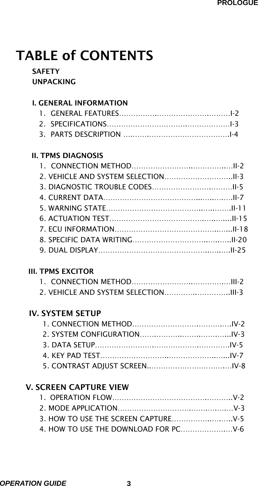
![APPENDIX IMPORTANT MESSAGE DESCRIPTION ABNORMAL VEHICLE POWER CHECK AND PRESS [ENTER] This message occurs when the external power supply is not connected or is lower than 9.0V. The user must supply sufficient external power. AUTO POWER OFF The TPMS EXCITER system will be powered off automatically because a TPMS EXCITER system error has occurred. BATTERY VOLTAGE LOW! RECHARGE BATTERY The voltage of the TPMS EXCITER rechargeable BATTERY is lower than the normal voltage. The user must recharge the battery with an external power supply or change the battery. CAN’T COMMUNICATION PLEASE CHECK THE SYSTEM The TPMS EXCITER cannot perform the communication because the system status is abnormal. The user must inspect the system.](https://usermanual.wiki/NEXTECH/TE315M/User-Guide-549921-Page-68.png)
![APPENDIX OPERATION GUIDE AP-2 COMMUNICATION ERROR CHECK THE SYSTEM, PRESS [ENTER] A communication error occurs when the TPMS EXCITER displays data which is received via communication. After checking the system, press the ENTER key. DIFFERENT SYSTEM PLEASE CHECK THE SYSTEM This message occurs after opening the communication, when the system is different from the system selected by the user. After checking the system, the user should select the correct system again. NO TROUBLE CODE TO ERASE This message occurs when the user press the ERAS key with no DTC to erase in DIAGNOSTIC TROUBLE CODE mode. SELECT ITEM WITH [FIX] This message occurs when the GRPH key is pressed without any item selected in the CURRENT DATA mode, or RCRD key is pressed without any item selected in the FLIGHT RECORD mode. In these cases, you must select an item with the FIX key. SYSTEM ROM ERROR! This message occurs when an error occurs in the ROM(Read Only Memory) of the TPMS EXCITER. If you are](https://usermanual.wiki/NEXTECH/TE315M/User-Guide-549921-Page-69.png)