NEXTECH TE315M TPMS Exciter User Manual TPMS GENE
NEXTECH CO., LTD. TPMS Exciter TPMS GENE
NEXTECH >
User Manual

OPERATION MANUAL

PROLOGUE
OPERATION GUIDE
2
CAUTION : Any changes or modifications in construction
of this device which is not expressly approved by the
party Responsible for compliance could void the user’s
authority to operate the equipment.
NOTE : This equipment has been tested and found to
comply with the limits for a Class A digital device,
pursuant to part 15 of the FCC Rules. The limits are
designed to provide reasonable protection against
harmful interference when the equipment is operated in
commercial environment. This equipment generates,
uses, and can radiate radio frequency energy and, if not
installed and used in accordance with the instruction
manual, may cause harmful interference to radio area is
likely to cause harmful interference in which case the
user will be required to correct the interference at his
own expense.
PROLOGUE
OPERATION GUIDE
3
TABLE of CONTENTS
SAFETY
UNPACKING
I. GENERAL INFORMATION
1. GENERAL FEATURES…………….………………….………I-2
2. SPECIFICATIONS…………………………….………………I-3
3. PARTS DESCRIPTION ….…….…………………………….I-4
II. TPMS DIAGNOSIS
1. CONNECTION METHOD……………………..…………..…II-2
2. VEHICLE AND SYSTEM SELECTION………………………..II-3
3. DIAGNOSTIC TROUBLE CODES…………………….………II-5
4. CURRENT DATA…………………………………...…..….….II-7
5. WARNING STATE…………………………………..…..…….II-11
6. ACTUATION TEST………………………………….…..…....II-15
7. ECU INFORMATION……………………………………..…...II-18
8. SPECIFIC DATA WRITING…………………………..…..…..II-20
9. DUAL DISPLAY………………………………………..…..….II-25
III. TPMS EXCITOR
1. CONNECTION METHOD……………………..………….…III-2
2. VEHICLE AND SYSTEM SELECTION…………..…………..III-3
IV. SYSTEM SETUP
1. CONNECTION METHOD……………………….……….….IV-2
2. SYSTEM CONFIGURATION…….………..……..…….…...IV-3
3. DATA SETUP…………………….……………….………….IV-5
4. KEY PAD TEST………………………..………………..…...IV-7
5. CONTRAST ADJUST SCREEN..………………………….…IV-8
V. SCREEN CAPTURE VIEW
1. OPERATION FLOW………………………………….………..V-2
2. MODE APPLICATION………………………….…….….….…V-3
3. HOW TO USE THE SCREEN CAPTURE……………..….…..V-5
4. HOW TO USE THE DOWNLOAD FOR PC……………….…V-6
PROLOGUE
OPERATION GUIDE
4
SAFETY
Safety Precautions
This equipment described in this manual is intended for use only
by qualified personnel. Safe and effective use of this equipment is
dependent upon the operator following normally accepted safety
practices and procedures in conjunction with the special
requirements detailed in this manual. Specific warning and cautionary
statements will be found, where applicable, throughout this manual.
Where necessary, the WARNING statements and ICON will be
described in this guide.
WARNING identifies conditions or actions which may damage
TPMS EXCIER or the vehicle.
IMPORTANT WARNING MESSAGES FOR SAFETY ARE
AS FOLLOWS:
DO NOT DROP TPMS EXCITER MAIN BODY. AND
TPMS EXCITER MUST ALWAYS BE COVERED BY THE
SHROUD
DO NOT PLACE TPMS EXCITER UPON DISTRIBUTOR
OF VEHICLE.
STRONG ELECTRO-MAGNETIC INTERFERENCE CAN
DAMAGE TPMS EXCITER.
A STRONG SURGE OR ELECTRONIC SHOCK IN THE
POWER SUPPLY LINE CAN DAMAGE TPMS EXCITER
POWER SUPPLY. DO NOT USE TPMS EXCITER UNDER
THESE HARSH ENVIRONMENT.
PROLOGUE
OPERATION GUIDE
5
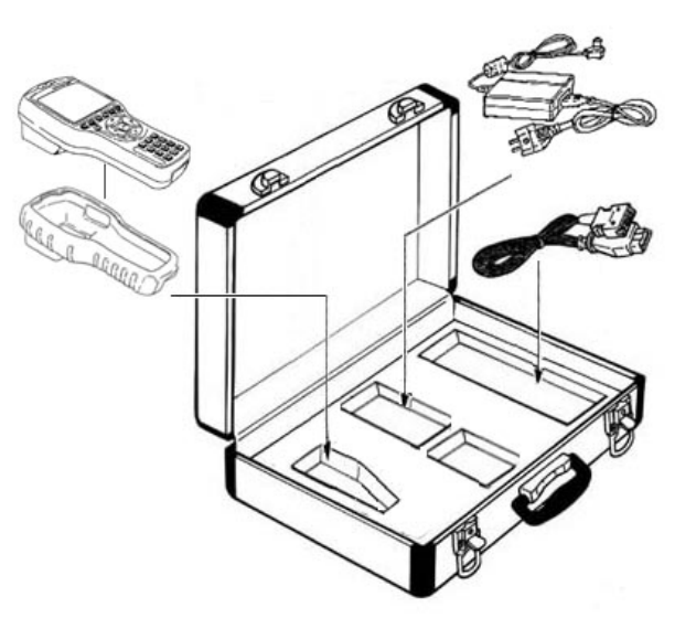
UNPACKING
The TPMS EXCITER kit comprises the following
standard along with the option kit where ordered.
The kit contents should be checked upon receipt and
damage or shortages reported to the supplier
immediately.
[ Figure 0.1 : TPMS EXCITER KIT ]

PROLOGUE
OPERATION GUIDE
6
1. STANDARD KIT
PART NO. PART NAME
1 09900-33000 TPMS EXCITER MAIN BODY
2 09900-33030 DLC CABLE 16
3 09900-33080 CARRYING CASE
4 09900-33040 USB CABLE
5 09900-33060 OPERATION MANUAL
6 09900-33010 RUBBER SHROUD
7 09900-33070 S/W DOWNLOAD CD
8 09900-33050 AD/DC ADAPTOR
9 09900-33020 RECHAGERABLE BATTERY

PROLOGUE
OPERATION GUIDE
7
ICON
OPERATION LEVEL ICON
: LEVEL 1 OPERATION(INIT LEVEL)
: LEVEL 1 OPERATION(MENU LEVEL)
: LEVEL 1 OPERATION(MODE LEVEL)
MESSAGE RELATED ICON
: PROCESS / RESULT MESSAGE
: ERROR MESSAGE
: WARNING MESSAGE
APPLICATION HELP ICON
: SCREEN EXPLANATION
: OPERATION GUIDE
: HELP / TIPS
: NOTE
I. GENERAL INFORMATION
1. GENERAL FEATURES…………………….…………….I-2
2. SPECIFICATION……………..……………..…………..1-3
3. PARTS DESCRIPTION…………………….……………I-4
GENERAL INFORMATION
OPERATION GUIDE I-2
1. General Features
TPMS EXCITER offers the following functionality:
On board diagnostic communication
Special vehicle test emulation
TMPS EXCITER feature include:
Diagnostic TPMS communication with HYUNDAI
vehicle
Diagnostic TPMS communication with KIA vehicles
High resolution LCD display
Soft touch key
Shock protecting rubber shroud
PC communication facility
PC software download with USB

GENERAL INFORMATION
OPERATION GUIDE I-3
2. SPECIFICATION
CASING Dark gray color
High strength ABS material
LCD SPEC. 320 by 240 resolution
LED Backlight type
Standard character output :40 columns 12
Lines
KEYPAD Power ON /OFF Key, Soft Function 6
Keys, Arrow 4 Keys, Fixed Functional 4
Keys
NUBER 0~9 KEY(10), Enter,ESC,YES/NO
Key.
Type : Soft Touch Keypad
MEMORY
CAPACITY
Internal Memory :
16 Mbytes Built-in memory
OPERATION
VOLTAGE
7 – 36 VDC INPUT
OPERATING
TEMPERATURE
0°C -50°C
DLC COMMUNI-
CATION LINE
TPMS K-Line
CAN
SAE-J1850
DIMENSION Width : 125mm
Length : 223mm
Depth : 68/43mm (neck part)
BATTERY SMART LI-ION BATTERY, 7 HOUR LIFE
FREQUENCY 125KHZ, 315MHZ(AM/FM)
POWER
CONSUMPTION
3.6 Watts
GENERAL INFORMATION
OPERATION GUIDE I-4
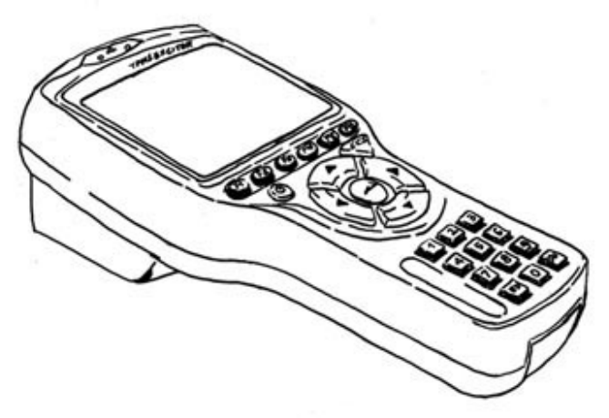
3. TPMS EXCITER Parts Description
(1) TPMS EXCITER MAIN BODY
(Part No: 09900-33000)
The TPMS EXCITER main body is illustrated in figure I.1.
[Figure I.1: TPMS EXCITER MAIN BODY]

GENERAL INFORMATION
OPERATION GUIDE I-5
(2) DLC CABLE 16
(Part no: 09900-33030)
The cable is illustrated in figure I.2 and is used to connect
the main body to the diagnosis terminal of vehicles with 16
pin connector vehicles.
[Figure I.2: DLC CABLE 16]

GENERAL INFORMATION
OPERATION GUIDE I-6
(3) CARRYING CASE
(Part no: 09900-33080)
The carrying case illustrated in figure I.3 provides for easy
transportation of TPMS EXCITER and protection for the
unit when not in use.
[Figure I.3: CARRYING CASE]

GENERAL INFORMATION
OPERATION GUIDE I-7
(4) USB CABLE
(Part no: 09900-33040)
The cable is illustrated in figure 1.4 and interfaces between
the TPMS EXCITER main body and PC when S/W download.
[Figure I.4: USB CABLE]
GENERAL INFORMATION
OPERATION GUIDE I-8
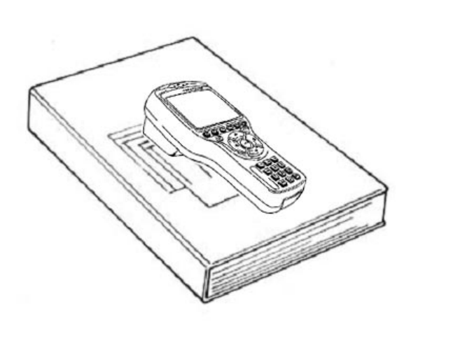
(5) OPERATION MANUAL
(Part no: 09900-33060)
The guide, illustrated in figure 1.6 provides TPMS EXCITER
user Instruction.
[Figure I.5: OPERATION MANUAL]
GENERAL INFORMATION
OPERATION GUIDE I-9
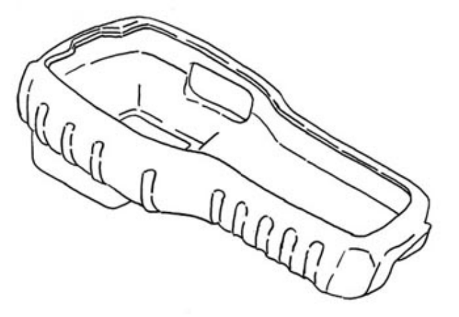
(6) RUBBER SHROUD
(Part no: 09900-33010)
The rubber shroud is used to protect the main body
from damage when in use.
[Figure I.6: RUBBER SHROUD]

GENERAL INFORMATION
OPERATION GUIDE I-10
(7) S/W DOWNLOAD CD
(Part no: 09900-33070)
The S/W DOWNLOAD CD is used to install the S/W
DOWNLOAD program.
[ Figure I.7 : S/W DOWNLOAD CD]
GENERAL INFORMATION
OPERATION GUIDE I-11
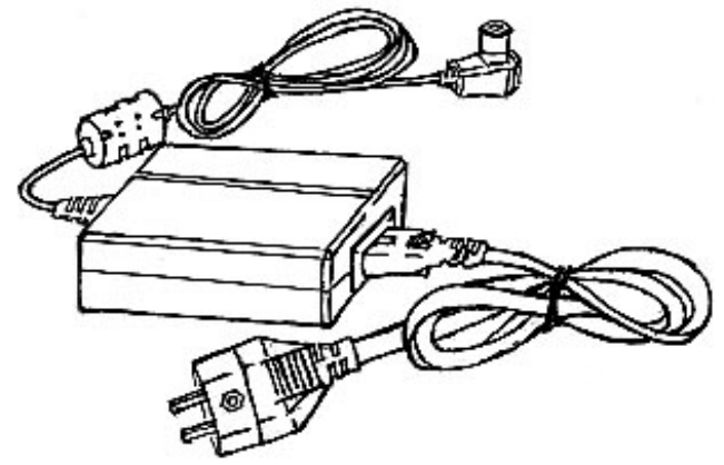
(8) AC/DC ADAPTOR(12V 3A)
(Part no : 09900-33050)
The AC/DC ADAPTOR provides power to the TPMS EXCITER
when updating the software with the S/W DOWNLOAD
ADAPTOR.
[ Figure I.8 : AC/DC ADAPTOR]
II. TPMS DIAGNOSIS
1.CONNECTION METHOD………………………..……………II-2
2.VEHICLE AND SYSTEM SELECTION…………..…………...II-3
3.DIAGNOSTIC TROUBLE CODES…………………..….……II-5
4.CURRENT DATA………………………….………….……….II-7
5.WARNING STATE………..………………..………………….II-11
6.ACTUATION TEST…………………………………………....II-15
7.ECU INFORMATION………………………..………………...II-18
8.SPECIFIC DATA WRITING……………….…………………..II-20
9.DUAL DISPLAY…………..……………………..……………..II-25
TPMS DIAGNOSIS
OPERATION GUIDE II-2
1. CONNECTION METHOD
For vehicles with DLC 16 pin Data Link Connector, power
is supplied from the DLC terminal through the DLC
CABLE without the need for an additional power supply.
For these vehicles connection of the DLC CABLE 16 to
the TPMS EXCITER and the vehicle data link terminals is
all that is required.
Once the power supply has been connected, the DLC
CABLE 16 should be connected to TPMS EXCITER data
link terminal and the DLC CABLE ADAPTER connected to
the vehicle data link terminal and the DLC CABLE 16.
TPMS DIAGNOSIS
OPERATION GUIDE II-3
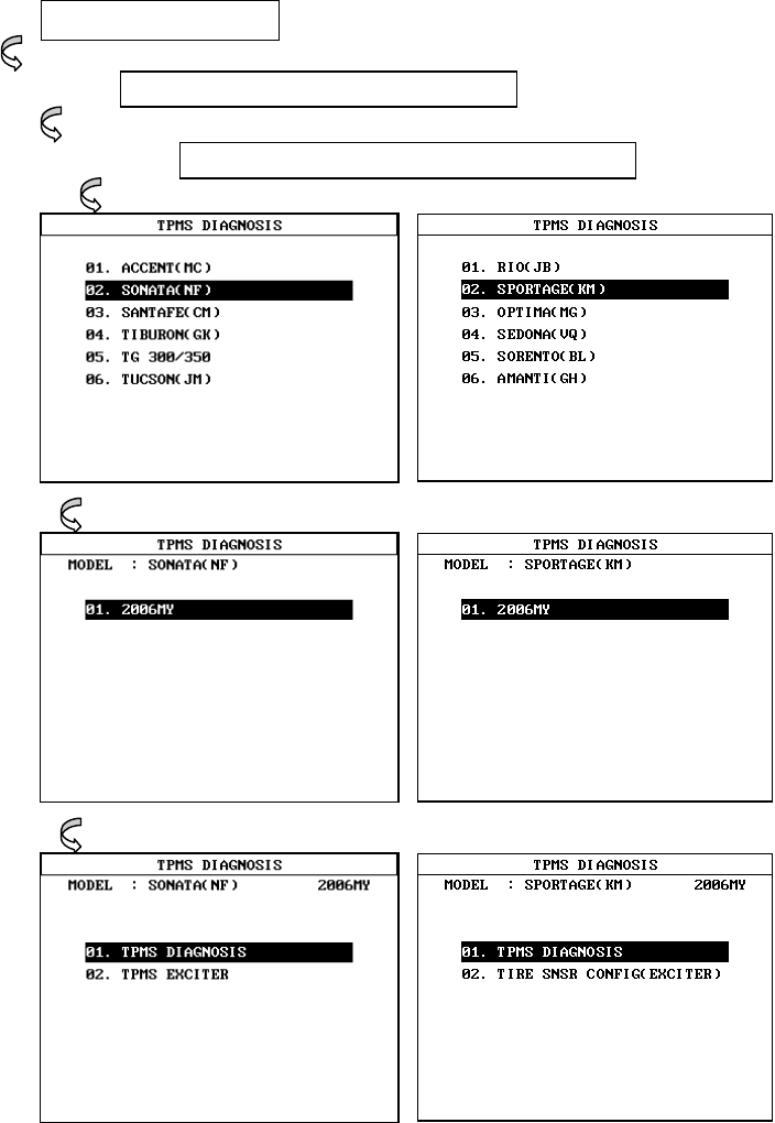
2. VEHICLES AND SYSTEM SELECTION
2-1. OPERATION FLOW
INITIAL MENU
TPMS DIAGNOSIS
HYUNDAI/KIA VEHICLE DIAGNOSIS
[FLOW II.1: VEHICLE AND SYSTEM SELECTION SUB-MENU IN/OUT]
TPMS DIAGNOSIS
OPERATION GUIDE II-4
2-2. BASIC APPLICATION
Having connected and turned on TPMS EXCITER,
the vehicle and systems 1 and 2 selections must
be made from the [ 1.0 VEHICLE DIAGNOSIS]
screen.
The support functions differ from vehicle to
vehicle and therefore the correct selection must
be made. Selection can be made by scrolling up or
down the screen and pressing ENTER.
Selection is made in the order of VEHICLE, SYSTEM
1, and SYSTEM 2.
TPMS DIAGNOSIS
OPERATION GUIDE II-5
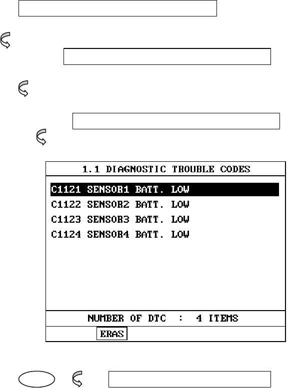
3. DIAGNOSTIC TROUBLE CODES
3-1. OPERATION FLOW
01. INITIAL SCREEN
VEHICLE AND SYSTEM SELECTION
Refer to “Selecting Vehicle Mode”
0.X DIAGNOSTIC TROUBLE CODES
ERAS 1.2.2
ERASE FAULT CODE
[FLOW II.2: DIAGNOSTIC TROUBLE CODES IN/OUT FLOW]

TPMS DIAGNOSIS
OPERATION GUIDE II-6
3-2. MODE APPLICATION
At this level, diagnostic trouble codes (DTC) are displayed for
the selected ECM
Whenever the screen is opened or refreshed, the cursor
moves to the beginning of the display and an audible
warning will be given along with the number and description
of the component from which the code has been generated.
By using the UP / DOWN key, the display may be scrolled.
EARS This soft function key will clear the DTC currently
held in the memory of the selected ECM. If this
option is selected, a message requesting
confirmation of the ERAS request will be displayed.
The ENTER or ESC key should be used to confirm
or cancel the request to clear the current DTC.
TPMS DIAGNOSIS
OPERATION GUIDE II-7
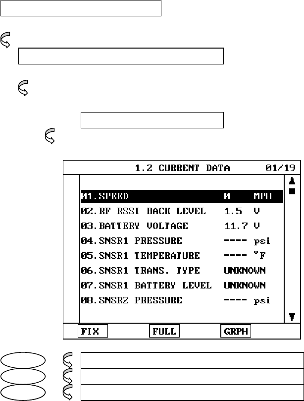
4. CURRENT DATA
4-1. OPERATION FLOW
01. INTIAL SCREEN
VEHICLE AND SYSTEM SELECTION
Refer to “Selecting Vehicle Mode”
0.2 CURRENT DATA
FIX 1.2.1 FIX ITEM
FULL 1.2.2 DISPLAY ALL ITEMS
GRPH 1.2.3 GRAPHICAL DISPLAY
[FLOW II.3: CURRENT DATA MODE IN/OUT FLOW]
TPMS DIAGNOSIS
OPERATION GUIDE II-8
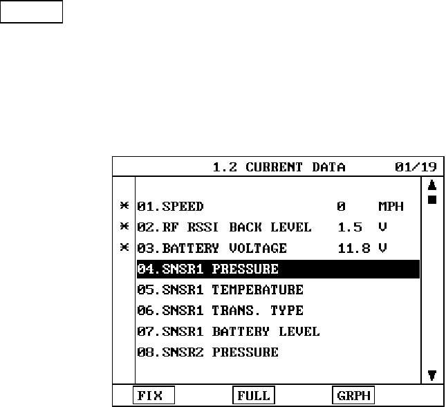
4-2. MODE APPLICATION
The sensor values and the ON/OFF state of the
system switches of the selected ECM are displayed.
Scrolling up and down the data is possible by means
of the UP / DOWN keys and more detailed data is
available by Using the soft function keys as follows:
FIX Executing the [FIX ITEM] function that moves the
item in inverted text to the top of the display. This
item is held and does not move when the cursor
keys are used to page through the display and
therefore allows specific items to be compared
directly to one another.
[Figure II.1: FIX ITEM]
TPMS DIAGNOSIS
OPERATION GUIDE II-9
A fixed item may be released by depressing the
FIX key again.
In the example, illustrated by [figure II.1], is fixed as
denoted by the asterisk to the left of the item
number.
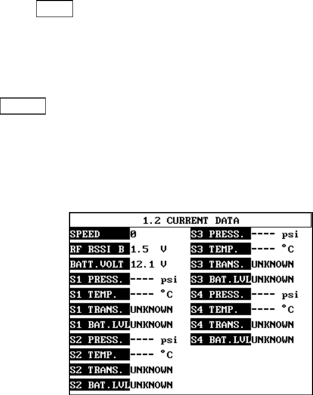
FULL Use of this key will cause maximum 22 data
value to be displayed on the screen as
illustrated in [figure II.2] The component
description displayed will be abbreviated when
this mode is used. The date may be scrolled by
use of the UP / DOWN key.
[Figure II.2: DISPLAY ALL ITEMS]
TPMS DIAGNOSIS
OPERATION GUIDE II-10
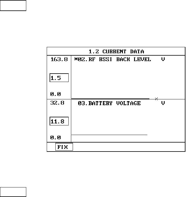
GRPH Where more 2 ‘active’ data items have been
selected using the FIX key, pressing the GRPH key
will cause the data for those items to be displayed
in the form of a graph as illustrated in [figure II.3].
[Figure II.3: CURRENT DATA (GRPH)]
FIX Holding one item of two. When the UP / DOWN keys
are used to scroll up and down the display, the
item selected by FIX key does not move.
TPMS DIAGNOSIS
OPERATION GUIDE II-11
5. WARNING STATE
5-1. OPERATION FLOW
0.1 INITIAL SCREEN
VEHICLE AND SYSTEM SELECTION
Refer to “Selecting Vehicle Mode”
0X. WARNING STATE
FIX 1.2.1 FIX ITEM
FULL 1.2.2 DISPLAY ALL ITEMS
[ FLOW II.4 : WARNING STATE MODE IN/OUT FLOW ]
TPMS DIAGNOSIS
OPERATION GUIDE II-12
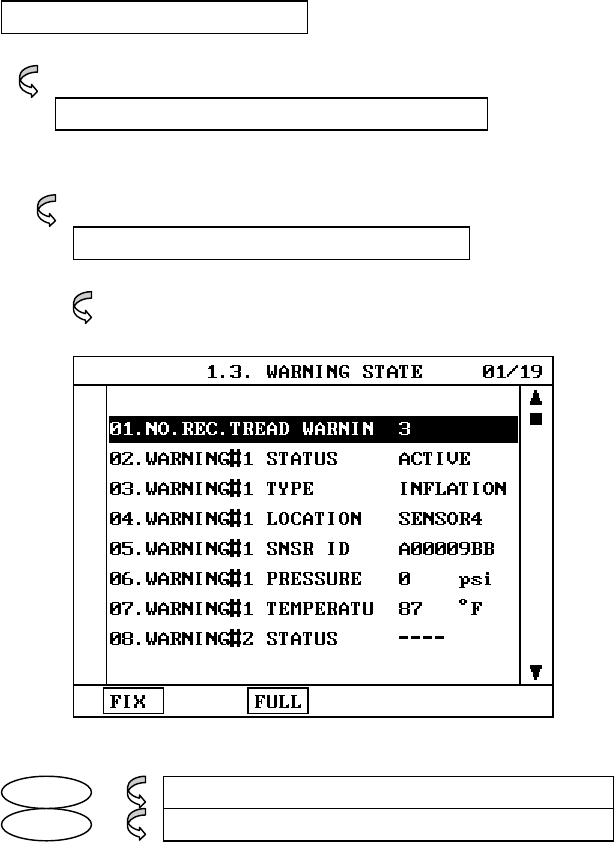
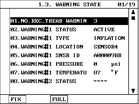
5-2. MODE APPLICATION
The WARNING STATE displays the data values stored in the
ECM at the point when the first DTC is detected.
A typical screen display is illustrated at [figure II.4].
[ Figure II.4:WARNING STATE DATA ]
TPMS DIAGNOSIS
OPERATION GUIDE II-13
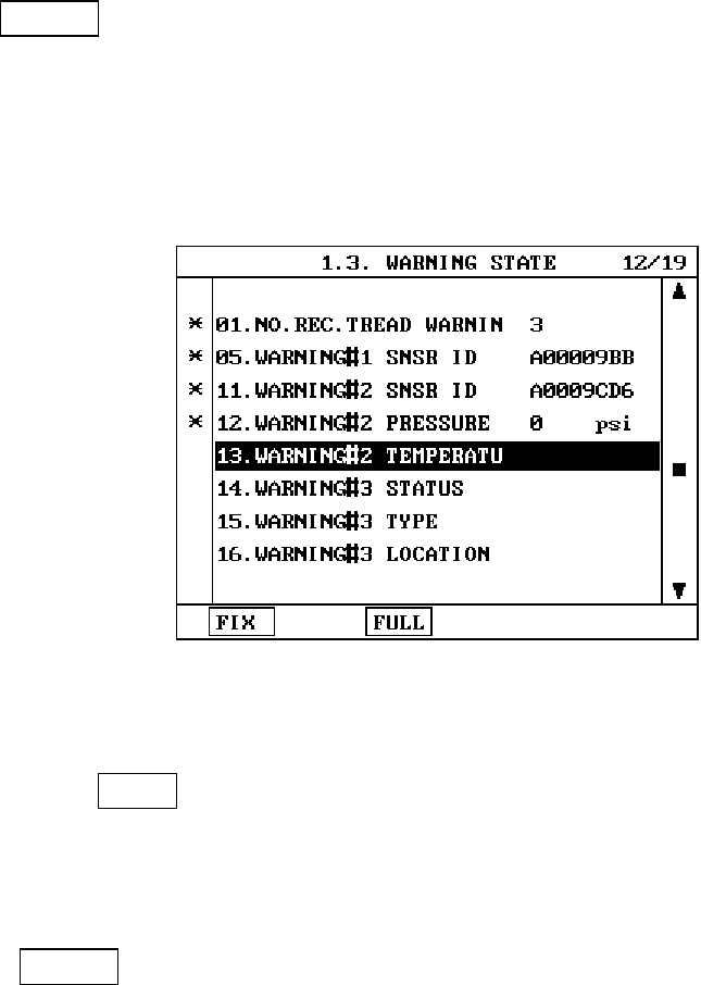
FIX Executing the [FIX ITEM] function that moves the
item in inverted text to the top of the display. This
item is held and does not move when the cursor
keys are used to page through the display and
therefore allows specific items to be compared
directly to one another.
[Figure II.5: FIX ITEM]
A fixed item may be released by depressing the
FIX key again.
In the example, illustrated by [figure II.5], is fixed as
denoted by the asterisk to the left of the item number.
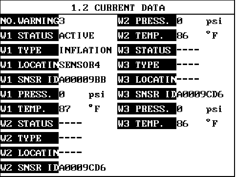
FULL Use of this key will cause maximum 22 data
value to be displayed on the screen as
illustrated in [figure II.6]. The component
description displayed will be abbreviated when
this mode is used. The date may be scrolled by
use of the UP / DOWN key.
TPMS DIAGNOSIS
OPERATION GUIDE II-14
[Figure II.6: DISPLAY ALL ITEMS]
TPMS DIAGNOSIS
OPERATION GUIDE II-15
6. ACTUATION TEST
6-1 OPERATION FLOW
0.1 INITIAL SCREEN
VEHICLE AND SYSTEM SELECTION
Refer to “Selecting Vehicle Mode”
0X. ACTUATION TEST
START START ACTIVATING
[FLOW II.5: ACTUATION TEST MODE IN/OUT FLOW]
TPMS DIAGNOSIS
OPERATION GUIDE II-16
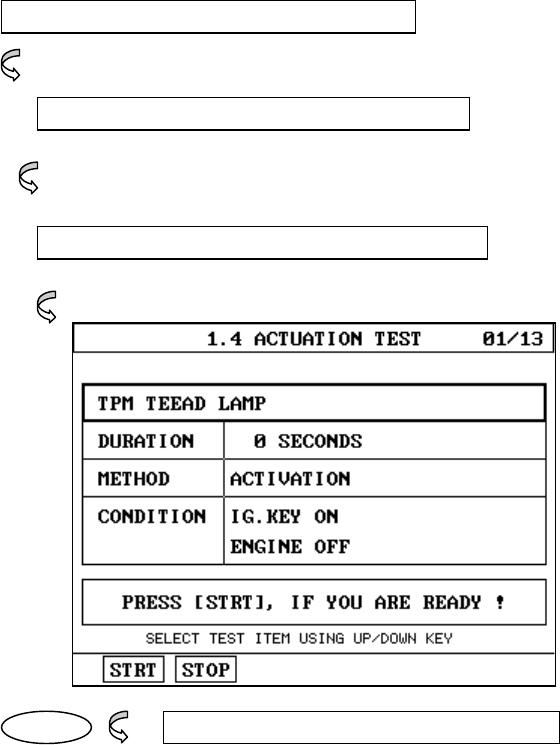
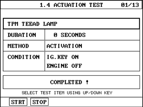
6-2 MODE APPLICATION
The ACTUATION TEST mode allows certain actuators to be
forcibly driven by TPMS EXCITER but this mode can only be
supported according to the selected vehicle. The illustration
of a typical screen is shown in [figure II.7].
The actuator to be driven can be changed by using the UP /
DOWN key to scroll through the list.
[Figure II.7: ACTUATOR DRIVING]
The test must be performed with the vehicle in the state
indicated by the CONDITION statement on the screen. In
this illustration given, for example, the ignition key must
be turned “on”, and the engine must be running.
The duration of the test will either be fixed by TPMS
EXCITER and indicated on the screen or the duration
dialogue will be indicated.

TPMS DIAGNOSIS
OPERATION GUIDE II-17
UNTIL STOP KEY
To begin an actuator test, the STRT key should be
pressed. For fixed duration test, the message
COMPLETED!
will be display after an acknowledged code has been
received from the vehicle. For tests of no fixed
duration, the message
NOW ACTIVATING
will be displayed once an acknowledged code has been
received from the vehicle and until the STOP key is
pressed. In both types of test, the message
TEST FAILURE!
will be displayed if no acknowledge code is received
from the Vehicle. The messages will be displayed for
0.5 seconds and then disappear.
TPMS DIAGNOSIS
OPERATION GUIDE II-18
7. ECU INFORMATION
7-1. OPERATION FLOW
01.INITIAL SCREEN
VEHICLE AND SYSTEM SELECTION
Refer to “Selecting Vehicle Mode”
0X. ECU INFORMATION
01. TPMS CONTROL MODULE INFO
02.CURRENT SENSOR ID
[FLOW II.6: ECU INFOR. MODE IN/OUT FLOW]
TPMS DIAGNOSIS
OPERATION GUIDE II-19
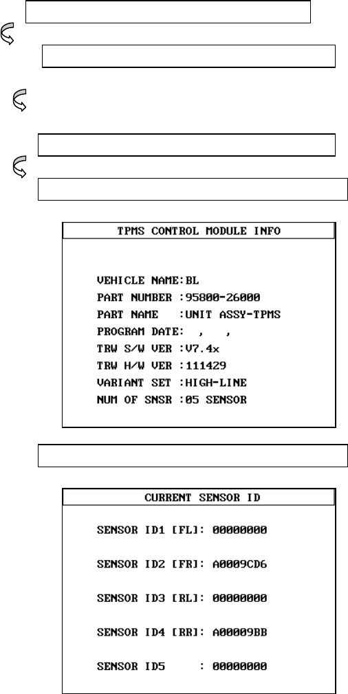
8-2 MODE APPLICATION
1) TPMS CONTROL MODULE INFO
This mode can check the a different kind of TPMS
CONTROL MODULE through by VEHICLE NAME, PART
NUMBER, PART NAME, PROGRAM DATE, S/W VER, H/W
VER. VARIANT SET, NUM OF SNSOR, SENSOR ID.
2) CURRENT SENSOR ID
This mode can show the sensor ID which is registered
in TPMS Receiver.
TPMS DIAGNOSIS
OPERATION GUIDE II-20
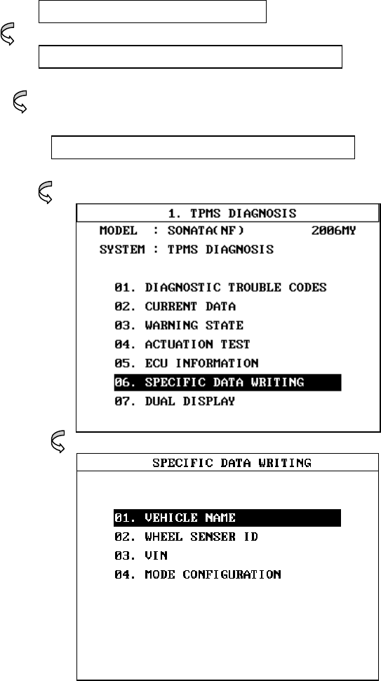
8. SPECIFIC DATA WRITING
8-1. OPERATION FLOW
0.1 INITIAL SCREEN
VEHICLE AND SYSTEM SELECTION
Refer to “Selecting Vehicle Mode”
0X. ECU INFORMATION
[FLOW II.7: SPECIFIC DATA WRITING MODE IN/OUT FLOW]
TPMS DIAGNOSIS
OPERATION GUIDE II-21
8-2 MODE APPLICATION
This mode can register the sensor ID when be changed the
TPMS Receiver or sensors.
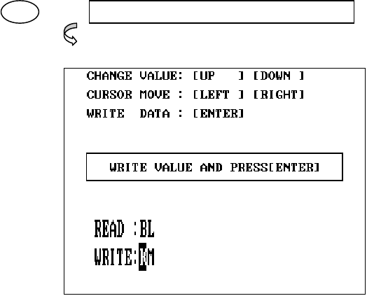
01 01. VEHICLE NAME
[Figure II.8 : VEHICLE NAME ]
This function is to input vehicle name chapter to
TPMS CONTROL MODULE. You must input vehicle
name correctly otherwise TPMS system may not operate
normally.
1. Change value : [UP ] , [DOWN] key
2. Cursor move : [ LEFT ] , [RIGHT] key
3. Write data : [ ENTER ] key
TPMS DIAGNOSIS
OPERATION GUIDE II-22
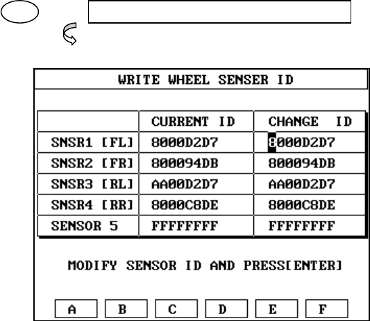
02 02. WHEEL SENSOR ID
[Figure II.9 : SENSOR ID DATA ]
This function is to input sensor ID to TPMS CONTROL
MODULE, Which is used to operate the TPMS system
properly the data is composed of 8 characters in
ARABIC number and ALPHABET.
[CURRENT ID] is current setting sensor ID
[CHANGE ID] is new writing sensor ID
1. Change value : [UP ], [DOWN] key
ALPHABET value : [F1] ~ [F6] key
ARABIC NUMBER : [0] ~ [9] key
2. Cursor move to left : [LEFT] key
Cursor move to right : [RIGHT] key
Cursor move to up : [ LEFT ] + [UP ] KEY
Cursor move to down : [ LEFT ] + [DOWN] KEY
3. Write the value : [ ENTER ]
TPMS DIAGNOSIS
OPERATION GUIDE II-23
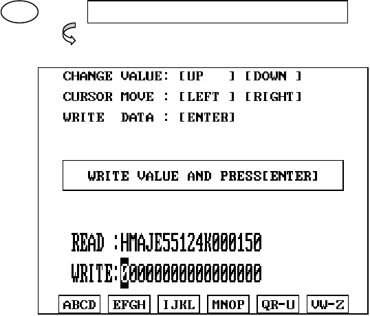
03 03. VIN
[Figure II.10 : VIN]
This function is to change the TPMS CONTROL
MODULE’S MODE.
Can read the vehicle VIN number and can write the
vehicle VIN number.
1. Change value : [UP ], [DOWN] KEY
2. Cursor move : [ LEFT ], [RIGHT] KEY
3. Write data : [ ENTER ] KEY
TPMS DIAGNOSIS
OPERATION GUIDE II-24
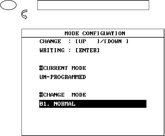
04 04. MODE CONFIGURATION
[Figure II.11 : VEHICLE NAME ]
This function is to change the TPMS CONTROL
MODULE’S MODE.
Write the sensor IDs, vehicle name and finally change
the normal mode.
1. Change : [UP ], [DOWN] key
2. Writing : [ENTER] key
TPMS DIAGNOSIS
OPERATION GUIDE II-25
9. DUAL DISPLAY
9-1. OPERATION FLOW
0.2 INITIAL SCREEN
VEHICLE AND SYSTEM SELECTION
Refer to “Selecting Vehicle Mode”
0X. DUAL DISPALYS
FIX FIX ITEM
CURR CURRENT DATA
DTC DIAG. TROUBLE CODES
[ FLOW I1.8 : DUAL DISPLAY MODE IN/OUT FOLW ]

TPMS DIAGNOSIS
OPERATION GUIDE II-26
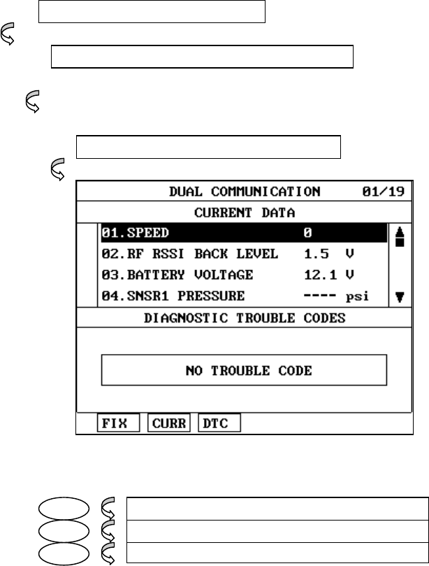
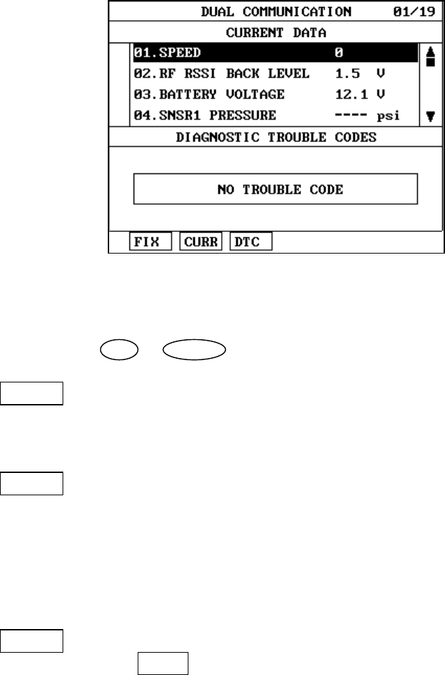
9.2 MODE APPLICATION
This facility allows for the display of the following
simultaneously:
• Current data items
• Available DTC
• Available freeze frame data items
The default screen is CURRENT DATA and DIAGNOSTIC
TROUBLE CODES (DTC).
The UP / DOWN key may be used to scroll the data
contained in the same window as the cursor.
Where a soft function key related to the current window is
used, the cursor will move to the selected area.
Where a soft function key related to the current window is
used, the window, which does not contain the cursor, will
be replaced with the soft function key related information.
TPMS DIAGNOSIS
OPERATION GUIDE II-27
A typical COMBINATION DISPLAY screen is illustrated at
figure IV.14.
[ Figure IV.14 : COMBINATION DISPLAY ]
The UP / DOWN key is used to scroll through the display.
FIX Holding one item of two. When the UP / DOWN keys
are used to scroll up and down the display, the
item selected by FIX key does not move.
CURR Taking the cursor to the CURRENT DATA AREA. If
the CURRENT DATA is being displayed, the CURR
key will Move the cursor to that window. If the
CURRENT DATA is not Being displayed, the window
not containing the cursor will Be replaced with the
CURRENT DATA display.
DTC DIAGNOSTIC TROUBLE CODES Work in a similar
manner to CURR except that the screen replaced is that
selected by the soft function key description.
III. TPMS EXCITER
1.CONNECTION METHOD………………………..……………III-2
2.TPMS EXCITER……………………………………….………...III-3
TPMS EXCITER
OPERATION GUIDE III-2
1. CONNECTION METHOD
For vehicles with DLC 16 pin Data Link Connector, power
is supplied from the DLC terminal through the DLC
CABLE without the need for an additional power supply.
For these vehicles connection of the DLC CABLE 16 to
the TPMS EXCITER and the vehicle data link terminals is
all that is required.
Once the power supply has been connected, the DLC
CABLE 16 should be connected to TPMS EXCITER data
link terminal and the DLC CABLE ADAPTER connected to
the vehicle data link terminal and the DLC CABLE 16.
TPMS EXCITER
OPERATION GUIDE III-3
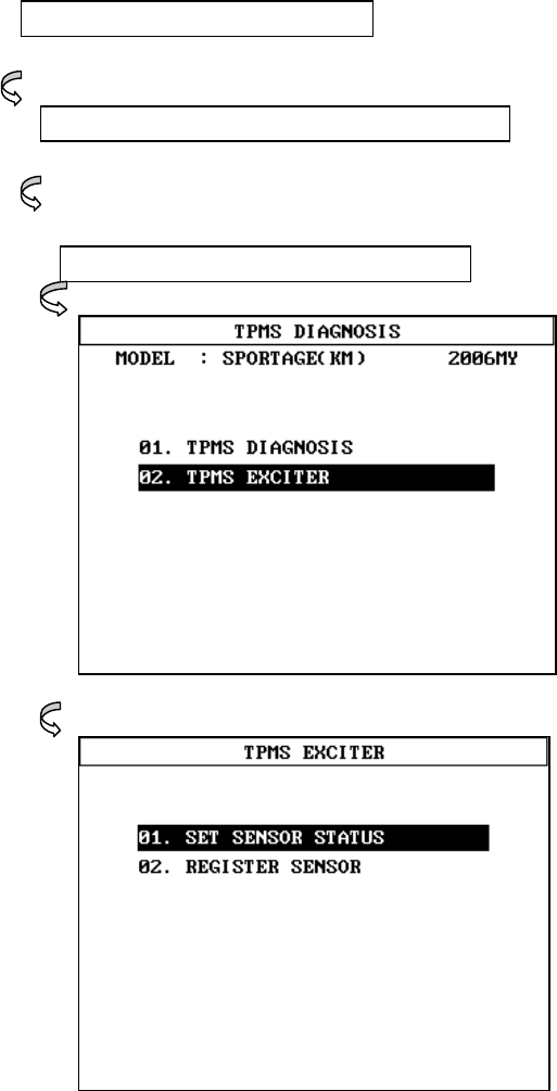
2. TPMS EXCITER
2-1. OPERATION FLOW
0.1 INITIAL SCREEN
VEHICLE AND SYSTEM SELECTION
Refer to “Selecting Vehicle Mode”
02. TPMS EXCITER
[ FLOW III.1 : TPMS EXCITER MODE IN/OUT FLOW ]
TPMS EXCITER
OPERATION GUIDE III-4
1-2 MODE APPLICATION
This mode can read the sensor IDs by RF communication
and then can change sensor status, register the sensor to
the TPMS CONTROL MODULE.
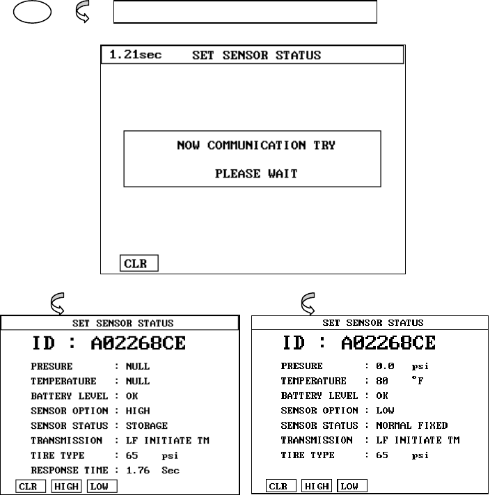
01 01.SET SENSOR STATUS
[Figure III.1: SET SENSOR STATUS]
PRESSURE : Display the NULL or real pressure of tire.
This values will be changed by sensor option.
TEMPERATURE : Display the NULL or real temperature of tire.
This values will be changed by sensor option.

TPMS EXCITER
OPERATION GUIDE III-5
BETTERY LEVEL : Display the OK or NG.
This values means the sensor battery status.
SENSOR OPTION : Display the HIGH or LOW.
This values can changed according to vehicle.
SENSOR STATUS : Display the NORMAL, STORAGE(SLEEP),
ALERT or OVER TEMP. WARNING.
TRANSMISSION : Display the LF INITIATE TM or NORMAL
TIMED TM.
If the sensor was communicated by TPMS EXCITER, LF
INITIATE TM will be display in the screen.
TIRE TYPE : Display the maximum measurement pressure
range of sensor.
CLR or ENTER : Reload the sensor status.
HIGH : Can change the sensor option, LOW to HIGH.
LOW : Can change the sensor option, HIGH to LOW.
TPMS EXCITER
OPERATION GUIDE III-6
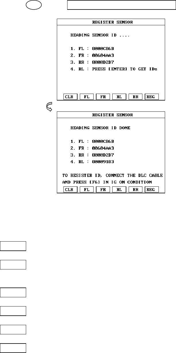
02 02.REGISTER SENSOR
[Figure III.2: REGISTER SENSOR ]
This mode can resister the sensor Ids to TPMS CONTROL MODULE
after reading the sensor IDs of the each tires.
CLR : Clear the screen.
REG : can resister the sensor Ids to TPMS CONTROL MODULE
with DLC cable.
FL : Can reload the FL sensor ID.
FR : Can reload the FR sensor ID.
RL : Can reload the RL sensor ID.
RR : Can reload the RR sensor ID.
IV. SYSTEM SETUP
1. CONNECTION METHOD……………………………IV-2
2. SYSTEM CONFIGURATION ….……………………..IV-3
3. DATA SETUP…………………………………………..IV-5
4. KEY PAD TEST.………………………………………..IV-7
5. CONTRAST ADJUST SCREEN……………………….IV-8
SYSTEM SETUP
OPERATION GUIDE IV-2
1. CONNECTION METHOD
The following two kinds of power supply methods can be used.
(1) DLC cable
(2) AC/DC adapter
SYSTEM SETUP
OPERATION GUIDE IV-3
2. SYSTEM CONFIGURATION
2-1. OPERATION FLOW
0.1 INITIAL SCREEN
X.0 SYSTEM SETUP
0.X SYSTEM CONFIGURATION
[FLOW IV.1 : SYSTEM CONFIGURATION MODE IN/OUT FLOW]
SYSTEM SETUP
OPERATION GUIDE IV-4
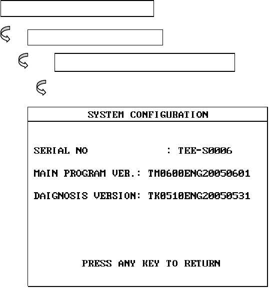
2-2. MODE APPLICATION
This mode displays data for the following items.
1) SERIAL NUMBER
: displays product serial number of your TPMS EXCITER
2) MAIN PROGRAM VERSION
: displays software version of MAIN PROGRAM
3) DAIGNOSIS PROGRAM VERSION
: displays software version of DAIGNOSIS PROGRAM
SYSTEM SETUP
OPERATION GUIDE IV-5
3. DATA SETUP
3-1. OPERATION FLOW
0.1 INITIAL SCREEN
X.0 SYSTEM SETUP
0.X DATA SETUP
LEFT LEFT ITEM SELECTION
RIGHT RIGHT ITEM SELECTION
UP ITEM VALUE CHANGE +
DOWN ITEM VALUE CHANGE-
ENTER CONFIRM ITEM SELECTION
[ FLOW IV.2 : DATA SETUP MODE IN/OUT FOLW ]
SYSTEM SETUP
OPERATION GUIDE IV-6
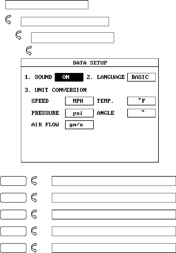
3.2 MODE APPLICATION
The operating parameters of the TPMS EXCITER may
be set prior to vehicle testing. The following list
details items which are user configurable.
1) SOUND : Determines whether or not the internal
beep sounds at each key depression.
2) LANGUAGE : Determines whether or not a local
language is used.
3) UNIT CONVERSION : The units of measurement
used by HI SCAN LITE may be selected from
either of the following :
Speed Km/h, MPH
Temperature Fahrenheit, Centigrade
Pressure kPa, mmHg, inHg, psi, mbar
Angle degree, percent
Airflow Volume gm/s , Ib/m
Items are selected by using the LEFT / RIGHT key,
and values may be changed using the UP / DOWN
key.
When editing by the Dealership, the cursor is moved
by using the LEFT / RIGHT key, and the selected
value is changed using the UP / DOWN key to
move to the next or previous character in the
character set ( 1, 2, 3 …, 9, 0, -, blank).
SYSTEM SETUP
OPERATION GUIDE IV-7
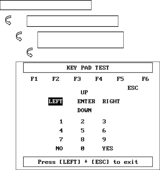
4. KEY PAD TEST
4-1. OPERATION FLOW
0.1 INITIAL SCREEN
X.0 SYSTEM SETUP
0.X KEY PAD TEST
[ FLOW IV.3 : KEY PAD TEST MODE IN/OUT FLOW ]
4-2. MODE APPLICATION
User can perform TPMS EXCITER self-test.
SYSTEM SETUP
OPERATION GUIDE IV-8
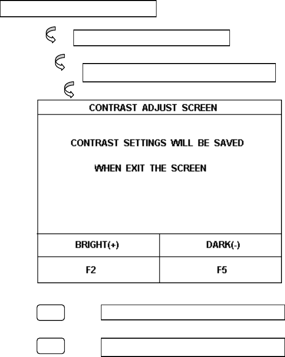
5. CONTRAST ADJUST SCREEN
5-1. OPERATION FLOW
0.1 INITIAL SCREEN
X.0 SYSTEM SETUP
0.X CONTRAST ADJUST SCREEN
F2 SCREEN IS BRIGHTER
F5 SCREEN IS DARKER
[ FLOW IV.4 : CONTRAST ADJUST SCREEN ]
SYSTEM SETUP
OPERATION GUIDE IV-9
5-2. MODE APPLICATION
This mode is for contrast adjustment because LCD’
bright-ness will change according to the temperature.
Contrast settings will be saved when exiting the screen.
V. SCREEN CAPTURE VIEW
1. OPERATION FLOW…………………………..……………... V-2
2. MODE APPLICATION……………………………..………....V-3
3. HOW TO USE THE SCREEN CAPTURE…………………..V-5
4. HOW TO USE THE DOWNLOAD FOR PC……..……..….V-6
SCREEN CAPTURE VIEW
OPERATION GUIDE V-2
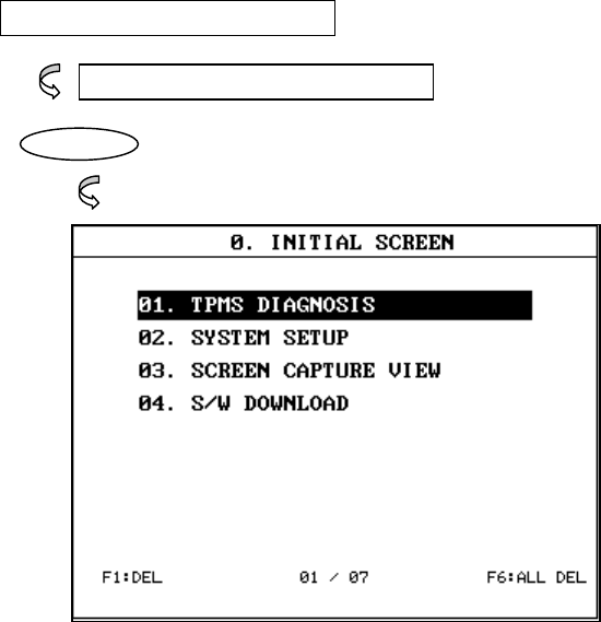
1. OPERATION FLOW
0.1 INITIAL SCREEN
0X. SCREEN CAPTURE VIEW
ENTER ‘
[ FLOW V.1 : SCREEN CAPTURE IN FLOW ]
SCREEN CAPTURE VIEW
OPERATION GUIDE V-3
2. MODE APPLICATION
TPMS EXCITER screen capture function can store 7-paged screen inside
internal flash memory of TPMS EXCITER.
In addition, when you see the relevant function, you can confirm through
the SCREEN CAPTURE VIEW MENU of TPMS EXCITER initial screen or TPMS
EXCITER download for PC.
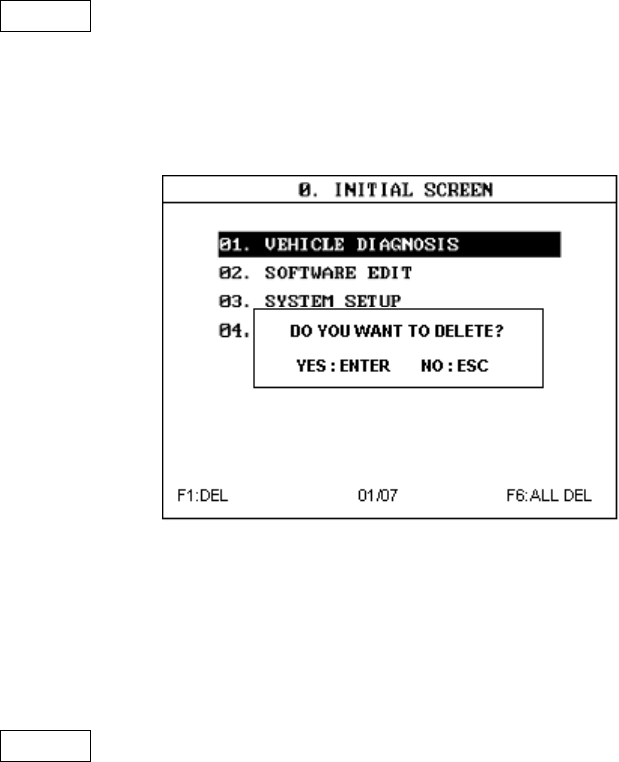
DEL This mode can delete the current screen. Press the F1
key If you want to delete the screen. A message will
display to delete on the screen. The example screen is as
follows:
[Figure V.2 : Screen DELETE ]
The current screen will be erased if you press ENTER.
01/07 The “01 “ is the current page number.
The “07” is the saved total pages number.
SCREEN CAPTURE VIEW
OPERATION GUIDE V-4
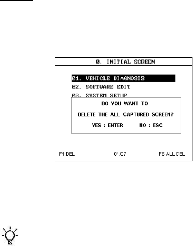
ALL DEL This mode can delete the all captured screens. Press the
F6 key If you want to delete the all screens. A message
will display to delete on the screen. The example screen
is as follows:
[Figure V.3 : All screens DELETE ]
The all captured screens will be erased if you press ENTER.
If disconnected the battery pack to TPMS EXCITER, The all
captured screens will be erased in the memory.
SCREEN CAPTURE VIEW
OPERATION GUIDE V-5
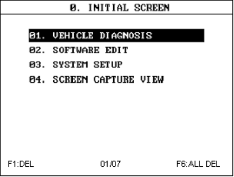
3. HOW TO USE THE SCREEN CAPTURE
1) At the screen which you want to save, press [LEFT+ENTER] key of TPMS
EXCITER.
2) If the screen is saved, the screen will be numbered following the
number of screen stored last.
If all seven screens are stored, 8th screen will overwrite and replace
the first screen and 8th will be the first.
3) You can check saved contents through SCREEN CAPTURE VIEW
Function of TPMS EXCITER MAIN CONTROL as SCRREEN-1
However, it will take time to load the saved screen.
[Figure V.4 :How to use the screen capture ]
SCREEN CAPTURE VIEW
OPERATION GUIDE V-6
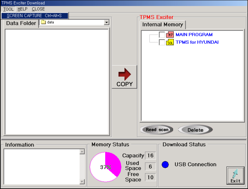
4. HOW TO USE THE DOWNLOAD FOR PC
1) Connect TPMS EXCITER and PC program through USB
2) As on [Figure V.4], press [TOOL] on the menu bar and select [SCREEN
CAPTURE (CTRL+ALT+S)]
[ Figure V.5 :How to use the download for pc ]
SCREEN CAPTURE VIEW
OPERATION GUIDE V-7
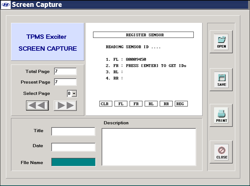
3) You will see the screen as the below [Figure V.5].
3.1) It will display the first screen of the initial TPMS EXCITER internal
memory.
3.2) You can change the picture clicking “Select Page” or [Left/right]
button.
3.3) After completion, press [Close] button.
[Figure V.6 : How to use the download for pc]

APPENDIX
IMPORTANT MESSAGE DESCRIPTION
ABNORMAL VEHICLE POWER
CHECK AND PRESS [ENTER]
This message occurs when the external power supply is not
connected or is lower than 9.0V. The user must supply
sufficient external power.
AUTO POWER OFF
The TPMS EXCITER system will be powered off
automatically because a TPMS EXCITER system error has
occurred.
BATTERY VOLTAGE LOW!
RECHARGE BATTERY
The voltage of the TPMS EXCITER rechargeable BATTERY is
lower than the normal voltage. The user must recharge the
battery with an external power supply or change the
battery.
CAN’T COMMUNICATION
PLEASE CHECK THE SYSTEM
The TPMS EXCITER cannot perform the communication
because the system status is abnormal. The user must
inspect the system.

APPENDIX
OPERATION GUIDE AP-2
COMMUNICATION ERROR
CHECK THE SYSTEM, PRESS [ENTER]
A communication error occurs when the TPMS EXCITER
displays data which is received via communication. After
checking the system, press the ENTER key.
DIFFERENT SYSTEM
PLEASE CHECK THE SYSTEM
This message occurs after opening the communication,
when the system is different from the system selected by
the user. After checking the system, the user should select
the correct system again.
NO TROUBLE CODE TO ERASE
This message occurs when the user press the ERAS key
with no DTC to erase in DIAGNOSTIC TROUBLE CODE
mode.
SELECT ITEM WITH [FIX]
This message occurs when the GRPH key is pressed
without any item selected in the CURRENT DATA mode, or
RCRD key is pressed without any item selected in the
FLIGHT RECORD mode. In these cases, you must select an
item with the FIX key.
SYSTEM ROM ERROR!
This message occurs when an error occurs in the
ROM(Read Only Memory) of the TPMS EXCITER. If you are
APPENDIX
OPERATION GUIDE AP-3
having a problem with the TPMS EXCITER, please try the
procedures in appendix B.