NEXXT SOLUTIONS NXG150 NexxtGate 150 High Power Access Point User Manual
NEXXT SOLUTIONS NexxtGate 150 High Power Access Point
UserManual.wiki
>
NEXXT SOLUTIONS
>
NXG150 User Manual
User Manual
Navigation menu
Upload a User Manual
Namespaces
Wiki Guide
HTML
PDF
Info
Views
User Manual
Discussion / Help
Navigation

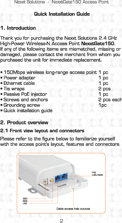
![Nexxt Solutions -NexxtGate150 Access Point 2.4 Checking the LEDs Upon powering on your access point. verify that the PWR and WlAN LEDs light up orange. 3. Location of the access point Before making any hardware connections, find a suitable location to place the access point. The best spot is usually at the center of the wireless network, with unobstructed line-of-sight to all wireless clients operating in the coverage area. Also consider that the higher the antenna is placed, the better the device can perform. Do not forget to make sure that the structure or pole you use to install the device is stable and properly secured. 1. If setting up the device in an indoor installation, use the keyholes on the brackets to mark the location on the wall where the access point is to be mounted. 2. Drill the holes and then drive the supplied anchors [if required] and screws into the wall . Leave the head of the screw slighgtly above the surface to hang the access point from the keyholes on the back. wall 5](https://usermanual.wiki/NEXXT-SOLUTIONS/NXG150/User-Guide-2516056-Page-5.png)
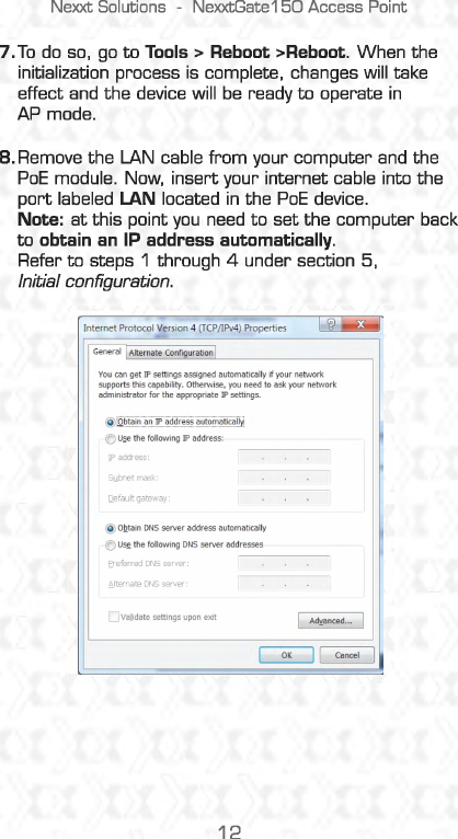
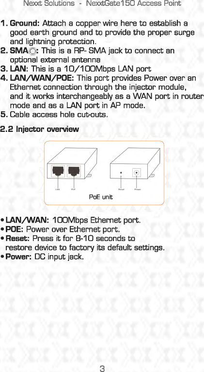
![Nexxt Solutions -NexxtGate150 Access Point 3.Select Internet Protocol Version 4 [TCP/1Pv4) and then go to Properties. You may also enable this option directly by double-<:licking on Internet Protocol Version 4 [TCP/1Pv4). Local Area Connection 2 Properties Networking ~S_h_a•_;n~g~-------------~ Connect using: rfj Reattek RTL8139/810xfamily fast Ethernet NIC This connection uses the following items: ~ :.L Client for Microsoft Networks ~ maoS Packet Scheduler ~ ~File and Printer Sharing for Microsoft: Networks ~ ...... Internet Protocol Version 6 (TCP/1Pv6) ~ .... I Internet Protocol Version 4 (TCP/1Pv4) I Configure ... ~ ...._ link-layer T apology Discovery Mapper VO Driver ~ ..... Link-Layer Topology Discovery Responder ~--ln_st_al_L. __ ] LUnmstall Properties Description Transmission Control Protocol/lntemetProtocoL The default wide area network protocol that provides communication across diverse interconnected networks. OK 11 Cancel 4.0nce the next dialog box comes up, select Use the following IP address option. The following items will become available: •IP address: Enter 192. 168.0. XXX (whereby X is any number between 2-253). •Subnet mask: Enter 255.255.255.0. 8](https://usermanual.wiki/NEXXT-SOLUTIONS/NXG150/User-Guide-2516056-Page-8.png)
![Nexxt Solutions -NexxtGate150 Access Point 5.Click OK twice to save your settings and complete the IP address configuration of the device. 5.1 Login 1.Start your WEB browser. Type http:/ /192.168.0.1 in the address field and press enter to continue. If) New Tab -Windows Internet Explorer u u @.] http://192l68.0l/ 2.A dialog box will prompt you to enter the User name and Password. By default, both are set to admin, in lowercase. Click login to complete this step. Login 3.Afterwards, you can assign a new password for security purposes without necessarily modifying the default user name. 4. If the login window fails to appear, it means that your Web-browser has been set to a proxy. Verify that your parameters and passwords are correct, before making another attempt. 9](https://usermanual.wiki/NEXXT-SOLUTIONS/NXG150/User-Guide-2516056-Page-9.png)