NEXXT SOLUTIONS NXG150 NexxtGate 150 High Power Access Point User Manual
NEXXT SOLUTIONS NexxtGate 150 High Power Access Point
User Manual

Nexxt
Solutions
-NexxtGate150 Access Point
Quick Installation Guide
1.
Introduction
Thank
you
for purchasing the Nexxt Solutions 2 .4
GHz
High-Power Wireless-N Access Point NexxtGate150.
If
any
of the following items are mismatched, missing
or
damaged, please contact the merchant from whom
you
purchased the unit for immediate replacement.
•
150Mbps
wireless long-range access point 1 pc
• Power adapter 1 pc
·~~~~~
1~
•
ne
wraps 2 pcs
• Passive
PoE
injector 1 pc
• Screws and anchors 2 pcs each
• Grounding screw 1 pc
• Quick installation guide
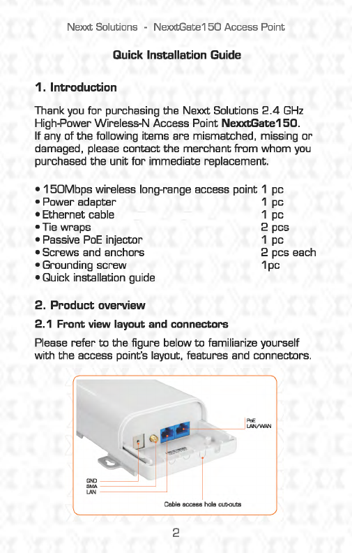
2. Product overview
2.1
Front
view
layout
and
connectors
Please refer to the figure below
to
familiarize yourself
with the access point's layout, features
and
connectors.
2
Nexxt
Solutions
-NexxtGate150 Access Point
1.
Ground
: Attach a copper wire here
to
establish a
good earth ground
and
to
provide the proper surge
and lightning protection.
2.
SMA
IQc
This
is
a
RP-
SMA jack
to
connect
an
optional external antenna
3.
LAN
: This is a
10/100Mbps
LAN
port
4.
LAN/WAN/POE:
This
port
provides Power over
an
Ethernet connection through the injector module,
and
it
works interchangeably as a WAN
port
in
router
mode
end
as a
LAN
port
in
AP
mode.
5.
Cable
access hole cut-outs.
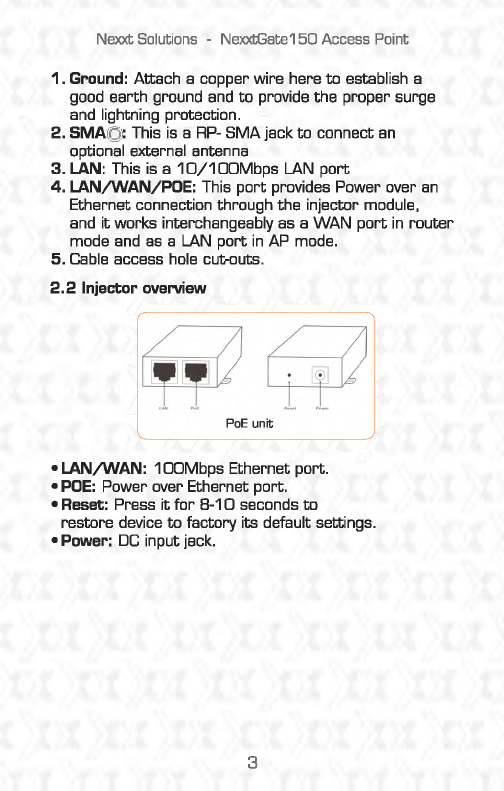
2.2
Injector overview
•LAN/WAN:
1 OOMbps Ethernet port.
•
PDE:
Power over Ethernet port.
• Reset: Press
it
for
8-10
seconds
to
restore device
to
factory its default settings.
•Power:
DC
input jack.
3
Nexxt Solutions -NexxtGate150 Access Point
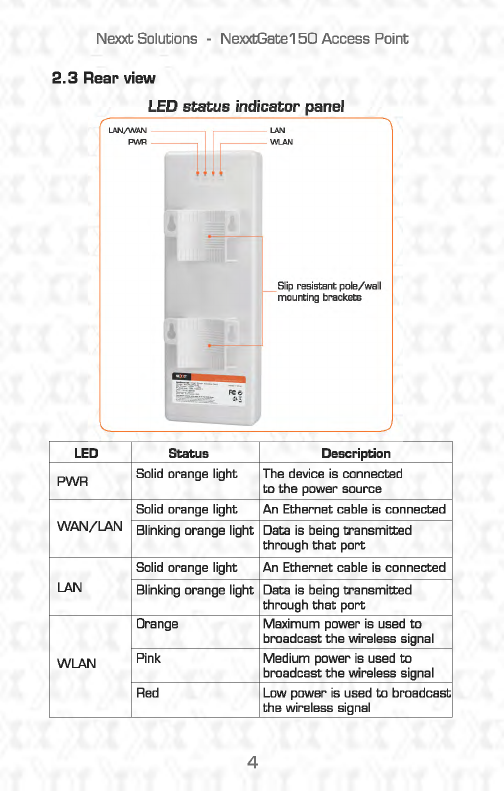
2.3
Rear
view
LED
status
indicator
panel
LED
Status
PWR Solid orange light
Solid orange light
WAN/LAN Blinking orange light
Solid orange light
LAN
Blinking orange light
Orange
WLAN Pink
Red
4
Slip
resistant pole/well
mounting
brackets
Description
The device is connected
to
the power source
An Ethernet cable
is
connected
Data is being transmitted
through
that
port
An
Ethernet cable
is
connected
Data is being transmitted
through
that
port
Maximum power is used
to
broadcast the wireless signal
Medium power
is
used
to
broadcast the wireless signal
Low power is used
to
broadcast
the wireless signal
Nexxt
Solutions -NexxtGate150 Access Point
2.4
Checking
the
LEDs
Upon powering
on
your access point. verify
that
the
PWR and
WlAN
LEDs
light up orange.
3.
Location of
the
access point
Before making any hardware connections, find a
suitable location
to
place the access point. The best
spot is usually
at
the center of the wireless network,
with unobstructed line-of-sight
to
all
wireless clients
operating
in
the coverage area.
Also consider
that
the higher the antenna is placed, the
better the device can perform.
Do
not forget
to
make
sure
that
the structure
or
pole
you
use
to
install the
device is stable and properly secured.
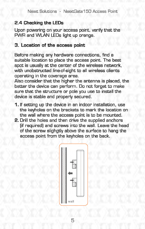
1.
If setting
up
the
device
in
an indoor installation, use
the keyholes
on
the brackets
to
mark
the location
on
the wall where the access point is
to
be
mounted.
2.
Drill the holes and then drive the supplied anchors
[if required] and screws into the wall .
Leave
the head
of the screw slighgtly above the surface
to
hang the
access point from the keyholes
on
the back.
wall
5
Nexxt
Solutions
-NexxtGate150
Access
Point
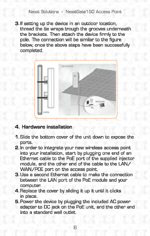
3.
If setting
up
the device
in
an
outdoor location,
thread the tie wraps trough the grooves underneath
the brackets.
Then
attach the device firmly
to
the
pole.
The
connection will be similar
to
the figure
below,
once the
above
steps
have
been successfully
completed.
pole
4.
Herdwere installation
1.
Slide the bottom cover of the unit down
to
expose the
ports.
2.
In
order
to
integrate your new wireless access point
into your installation,
start
by
plugging
one
end
of
an
Ethernet cable
to
the
PoE
port
of the supplied injector
module,
and
the other
end
of the cable
to
the
LAN/
WAN/POE
port
on
the access point.
3.
Use a second Ethernet cable
to
make the connection
between the LAN
port
of the
PoE
module
and
your
computer.
4.
Replace the cover
by
sliding
it
up
it
until
it
clicks
in
place.
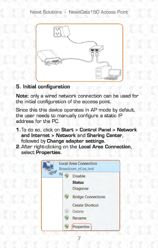
5. Power the device
by
plugging the included
AC
power
adapter
to
DC
jack
on
the
PoE
unit,
and
the other
end
into a standard wall outlet.
6
Nexxt Solutions -Ne:xxtGate150 Access Point
5.
Initial configuration
Note: only a wired network connection can
be
used
for
the
initial configuration of
the
access point.
Since
this this
device operates
in
AP mode
by
default,
the
user
needs
to
manually configure a static
IP
address
for
the
PC.
1.
To
do so, click
on
Start>
Control
Panel>
Network
and
Internet>
Network and Sharing Center,
followed
by
Change adapter settings.
2.After
right-clicking
on
the
Local
Area Connection,
select Properties.
Local Area Connection
Di
sab
le
St
atus
Diagnose
B
ri
dge
Connections
Create Shortcut
De
lete
Rename
Properti
es
7
Nexxt
Solutions
-NexxtGate150 Access Point
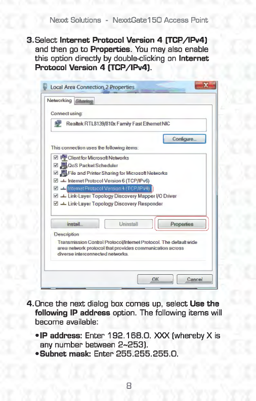
3.Select
Internet
Protocol Version 4 [TCP/1Pv4)
and then
go
to
Properties.
You
may also enable
this
option directly
by
double-<:licking
on
Internet
Protocol Version 4 [TCP/1Pv4).
Local Ar
ea
Connection 2 P
ro
pert
ies
Networking
~
S
_
h
_
a•
_
;
n
~g
~-------------~
Co
n
nect
usi
ng
:
rfj Reattek RTL8139/81
0xfamily
fast
Ethe
rn
et NIC
Th
is connection
uses
the following items:
~
:.L
Client
fo
r Microsoft Networks
~
maoS
Packet
Sc
h
edu
l
er
~
~Fi
l
e
and Printer Sharing for Microsoft: Networks
~
......
Internet Protocol Version 6 (TCP
/1
Pv6)
~
....
I Internet Protocol Version 4
(TCP/1Pv4)
I
Co
nfigure ...
~
...._
link-
layer
T apology Discovery
Mappe
r VO Driver
~
..... Link-Layer
Topology
Discovery Respon
der
~--
ln
_
s
t
_
al
_
L
.
__
]
LUnmstall
Pr
operties
Desc
ription
Tr
ansmi
ssio
n Control Prot
ocol/lntemetP
r
otoco
L The default
wide
area
network
pro
t
oco
l
tha
t
provides
commu
ni
cation
across
di
verse
interconnected networks.
OK
11 Cancel
4.0nce
the next dialog box comes up, select Use
the
following IP address option.
The
following items will
become available:
•IP
address: Enter
192.
168.0.
XXX (whereby X is
any number between
2-253)
.
•Subnet
mask: Enter
255.255.255.0.
8
Nexxt Solutions -NexxtGate150 Access Point
5.Click
OK
twice
to
save your settings and complete the
IP
address configuration of the device.
5.1
Login
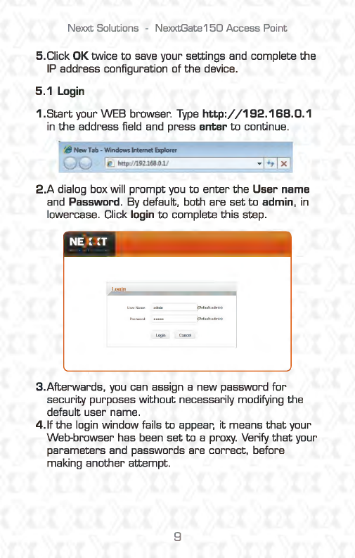
1.Start
your WEB browser.
Type
http:/
/192.168.0.1
in
the
address field and press enter
to
continue.
If)
New
Tab
-
Windows
Internet
Explorer
u u
@.]
http://192l68.
0l
/
2.A
dialog box will
prompt
you
to
enter
the
User name
and Password. By default, both are
set
to
admin,
in
lowercase. Click
login
to
complete this step.
Login
3.Afterwards,
you
can assign a new password
for
security purposes without necessarily modifying the
default user name.
4. If
the
login window fails
to
appear,
it
means
that
your
Web-browser has been
set
to
a proxy. Verify
that
your
parameters and passwords are correct, before
making another attempt.
9
Nexxt Solutions -NexxtGate150 Access Point
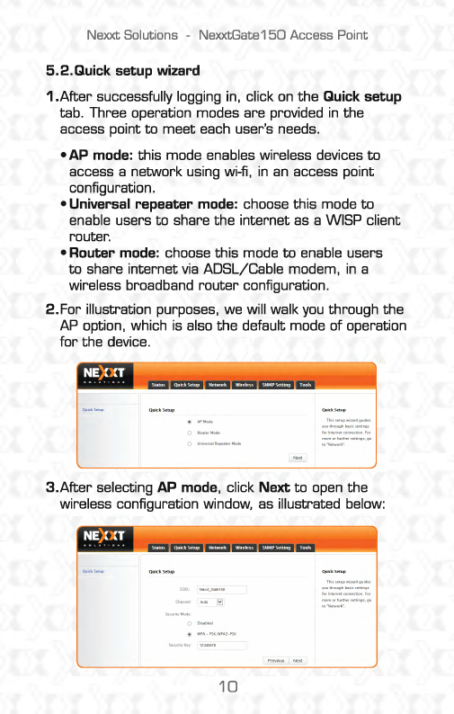
5.2.Quick setup wizard
1.After
successfully logging in, click
on
the Quick setup
tab. Three operation modes are provided
in
the
access point
to
meet
each user's needs.
•AP
mode: this mode enables wireless devices
to
access a network using wi-fi,
in
an
access point
configuration.
•Universal repeater mode: choose this mode
to
enable users
to
share the internet as a WISP client
router.
•Router
mode: choose this mode
to
enable users
to
share internet
via
ADSL/Cable modem,
in
a
wireless broadband
router
configuration.
2.For
illustration purposes, we will walk
you
through the
AP option, which is also the default mode of operation
for
the device.
3.After
selecting AP mode, click Next
to
open the
wireless configuration window, as illustrated below:
10
Nexxt Solutions -NexxtGate150 Access Point
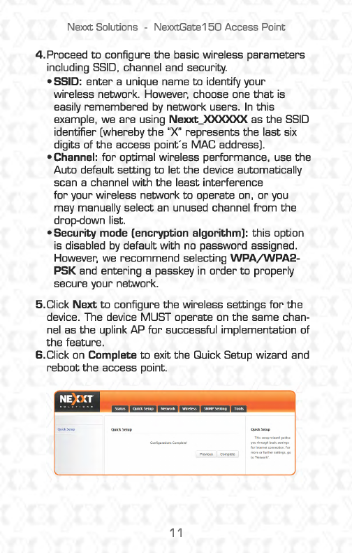
4.
Proceed
to
configure
the
basic wireless parameters
including
SSID,
channel and security.
• SSID:
enter
a unique name
to
identify your
wireless network. However, choose one
that
is
easily remembered
by
network users.
In
this
example, we are using Nexxt_XXXXXX as
the
SSID
identifier [whereby
the
"X" represents
the
last six
digits of the access point's MAC address).
•Channel:
for
optimal wireless performance, use the
Auto default setting
to
let
the
device automatically
scan a channel with
the
least interference
for
your wireless network
to
operate on,
or
you
may manually select
an
unused channel
from
the
drop-down list.
•Security
mode (encryption algorithm): this option
is disabled
by
default with no password assigned.
However, we recommend selecting
WPA/WPA2-
PSK and entering a passkey
in
order
to
properly
secure your network.
5.Click
Next
to
configure
the
wireless settings
for
the
device. The device MUST operate
on
the same chan-
nel as
the
uplink AP
for
successful implementation of
the
feature.
6.Click
on
Complete
to
exit the Quick Setup wizard and
reboot
the
access point.
11
Nexxt
Solutions -
NexxtGate1
50
Access Point
7.
To
do
so,
go
to
Tools
> Reboot >Reboot. When the
initialization process is complete, changes will take
effect and the device will be ready
to
operate
in
AP
mode.
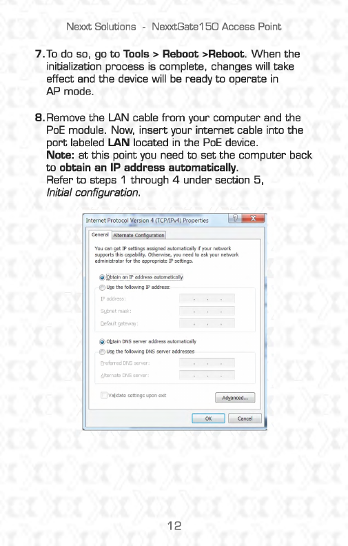
8. Remove the LAN cable
from
your computer and the
PoE
module. Now, insert your internet cable into the
port
labeled
LAN
located
in
the
PoE
device.
Note:
at
this point
you
need
to
set the computer back
to
obtain
an
IP address automatically.
Refer
to
steps 1 through 4 under section 5,
Initial configuration.
Internet Protocol Version 4 (TCP/IPv4) Properties
General lAlternate Configuration I
You
can get
IP
settings assigned automatically
if
your network
supports this capability. otherwise, you need
to
ask your network
administratorfortheappropriateIPsettings.
@
Q.~~~-~~
-
--~-~
-
--~-
-
~-~.9..~~-~-
..
~.~.t.~.~.~-~~-~.~.!.!'r!
~
U~thefollowingIPaddress:
IP
address:
Sybnetmask:
Qefaultgateway:
@OQtainDNSserveraddressautomaticalty
~
U~thefollowingDNSserveraddresses
E.referred DNSserver:
~
l
ternat:e
DNSserver
O
vajidatesettingsuponexit
12
Nexxt Solutions -NexxtGate150 Access Point
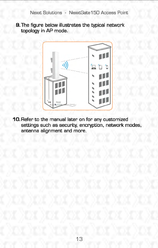
9.
The figure below illustrates the typical network
topology
in
AP mode.
..
...
:
;;);:
'g D 'o
··
.
...
a
..
•
••
..
•
••
..
•••
..
..
-I
..
•
••
10.
Refer
to
the
manual later on
for
any customized
settings such as security, encryption, network modes,
antenna alignment and more.
13
Nexxt
Solutions
-NexxtGate150
Access
Point
FCC
statement
This device complies with
Part
15
of the
FCC
Rules.
Operation is subject
to
the following two conditions:
(1
I This device may not cause harmful interference.
and
(2) this device must accept
any
interference
received, including interference
that
may cause
undesired operation.
This equipment has been tested
and
found
to
comply
with the limits
for
a Class B digital device. pursuant
to
Part
15
of the
FCC
Rules. These limits are designed
to
provide reasonable protection against harmful
interference
in
a residential installation.
This equipment generates. uses
and
can radiate radio
frequency energy
and,
if not installed
and
used
in
accordance with the instructions. may cause harmful
interference
to
radio communications. However, there
is
no
guarantee
that
interference will not occur in a par-
ticular installation.
If
this equipment does cause harmful
interference
to
radio
or
television reception, which can
be
determi
ned
by
turning the equipment off
and
on,
the
user is encouraged
to
try
to
correct the interference
by
one
of the following measures:
•Reorient
or
relocate the receiving antenna.
•Increase the separation between the equipment
and
receiver.
•Connect the equipment into
an
outlet
on
a circuit
different from
that
to
which the receiver
is
connected.
•Consult the dealer
or
an
experienced
radio/TV
technician
for
help.
14
NelCJCt
Solutions -NexxtGate150 Access Point
FCC
caution: Any changes
or
modifications not
expressly approved
by
the party responsible
for
compliance could void the user's authority
to
operate
this equipment.
This
transmitter
must
not
be
ccrlocated
or
operating
in
conjunction with any other antenna
or
transmitter.
The manufacturer is not responsible
for
any radio
or
TV
interference caused
by
unauthorized modifications
to
this equipment.
Radiation exposure
statement
This equipment complies with
FCC
radiation exposure
limits
set
forth
for
an uncontrolled environment.
This equipment should
be
installed and operated with
minimum distance
20cm
between the radiator and
your body.
FCCID:X4YNXG150
15