NEXXT SOLUTIONS XPYB3LL XpyBell User Manual JSW QSG RVDP OASP V1 1
NEXXT SOLUTIONS XpyBell JSW QSG RVDP OASP V1 1
Users manual
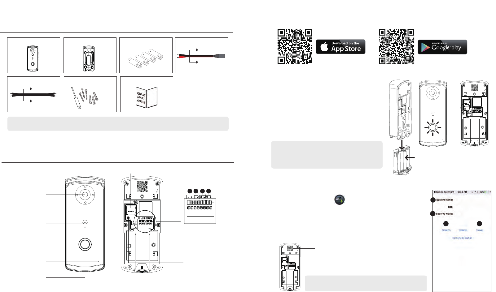
2. Insert Batteries
(1) Unscrew the battery compartment screw
with spplied screw driver.
(2) Insert the batteries supplied. Make sure the
polarity is as indicated before inserting the
battery cartridge back to RVDP.
(3) After the batteries are inserted, the Push
Button illuminator will light up and ash,
indicating RVDP is ready for further setup.
3. Setup RVDP via App
(1) While the push button illuminator is ashing Red&Blue,
launch the app and tap to add device.
(2) Scan QR code to bring up the DID or enter the DID manually
(The DID sticker is located at the back of the RVDP )
(3) Enter name for your RVDP (maximum 20 characters).
(4) Enter default Security Code: 123456.
(5) Tap "Save" and follow in-app wizard to complete the setup.
QUICK START GUIDE
KIT CONTENT :
1. App Download and Installation
(1) Please download and install the "OMGuard HD” APP to your device.
SETUP THE VIDEO DOORPHONE
(3)
Reset
Device ID: DOXX-123456-ABCDE (On Sticker)
Wi-Fi Pairing Mode:
SSID: RVDP-XXXXXX
Default PW:12345678
(1)
(2)
RVDP
x 1
Wall-Bracket
x 1
DC Power Cable
x 1x 4
Battery (Type AA)
Note: For video recording, BE SURE TO use CLASS 10 memory card or above . Other kinds of memory card may cause
unexpected results and should be avoided.
Screw Pack
x 1 x 1
Quick Start Guide
Black
Red
HARDWARE OVERVIEW
Memory Card Slot
I/O Pin Connector
1. AC/DC: Power Input I/O *
2. O2/O1: Wet Contact I/O
3. B2/B1: Dry Contact I/O
4. B2/B1: Dry Contact I/O
Reset Button
Note: On the back of the RVDP you will nd DID label containing
DID number, which you will need later on when resetting device.
Note: If the illuminator is not lighted,
press/hold the Reset Button for 5 seconds
until the illuminator lights up and ash.
2 5
4
3
*Power input jack can be safely connected with
AC/DC 9~36V power cable in any polarity
For iOS For Android
1 2 3 4
DOXX-123456-ABCDE
DOXX-123456-ABCDE
DOXX-123456-ABCDE
HD Camera
Speaker
Doorbell Button
Microphone
Battery Compartment
Dry/Wet Contact Cable
x 3
Black
Black
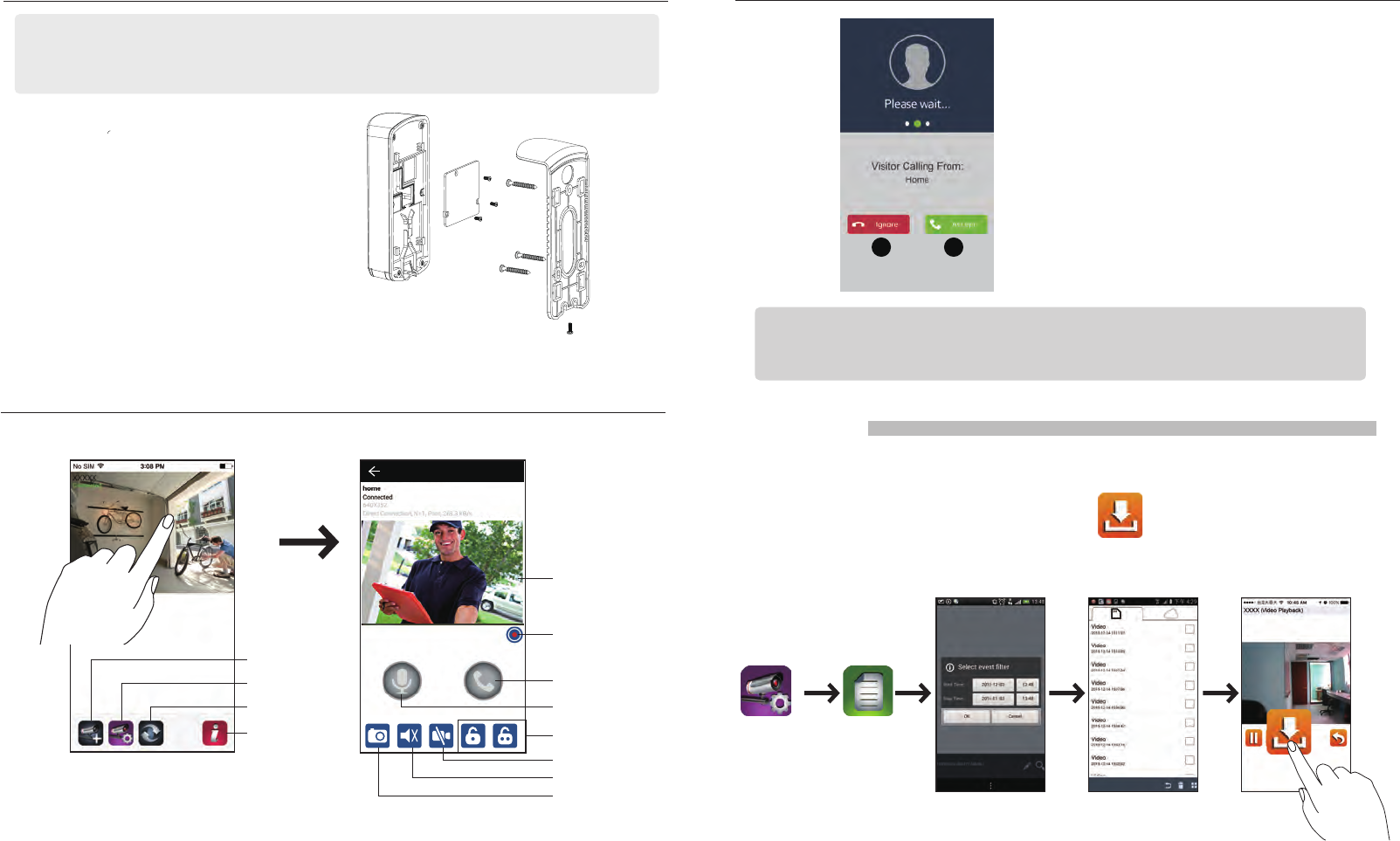
LIVE VIEW / SNAPSHOT / RECORDING
DOORPHONE INSTALLATION
LIVE VIDEO*
(1) Secure the wall bracket on a stable surface
(2) Mount the RVDP onto the wall bracket
(3) Secure the RVDP via the screw supplied.
Note:
(A) Battery Power Option is being illusestred here, therefore if you wish to power the RVDP via existing doorbell wires or optional
adaptor, please refer to owner's manual for more details.
(B) Before installation begins, it is suggested to turn o the "Power Saving" mode so you can have continuous connection via the
live-video while dening the installation location/height. Please refer to Power Saving Mode section of this document.
Information
*Available while RVDP not in Power Saving Mode.
Refresh
Device Setting
Add Device
(1)
(2)
(3)
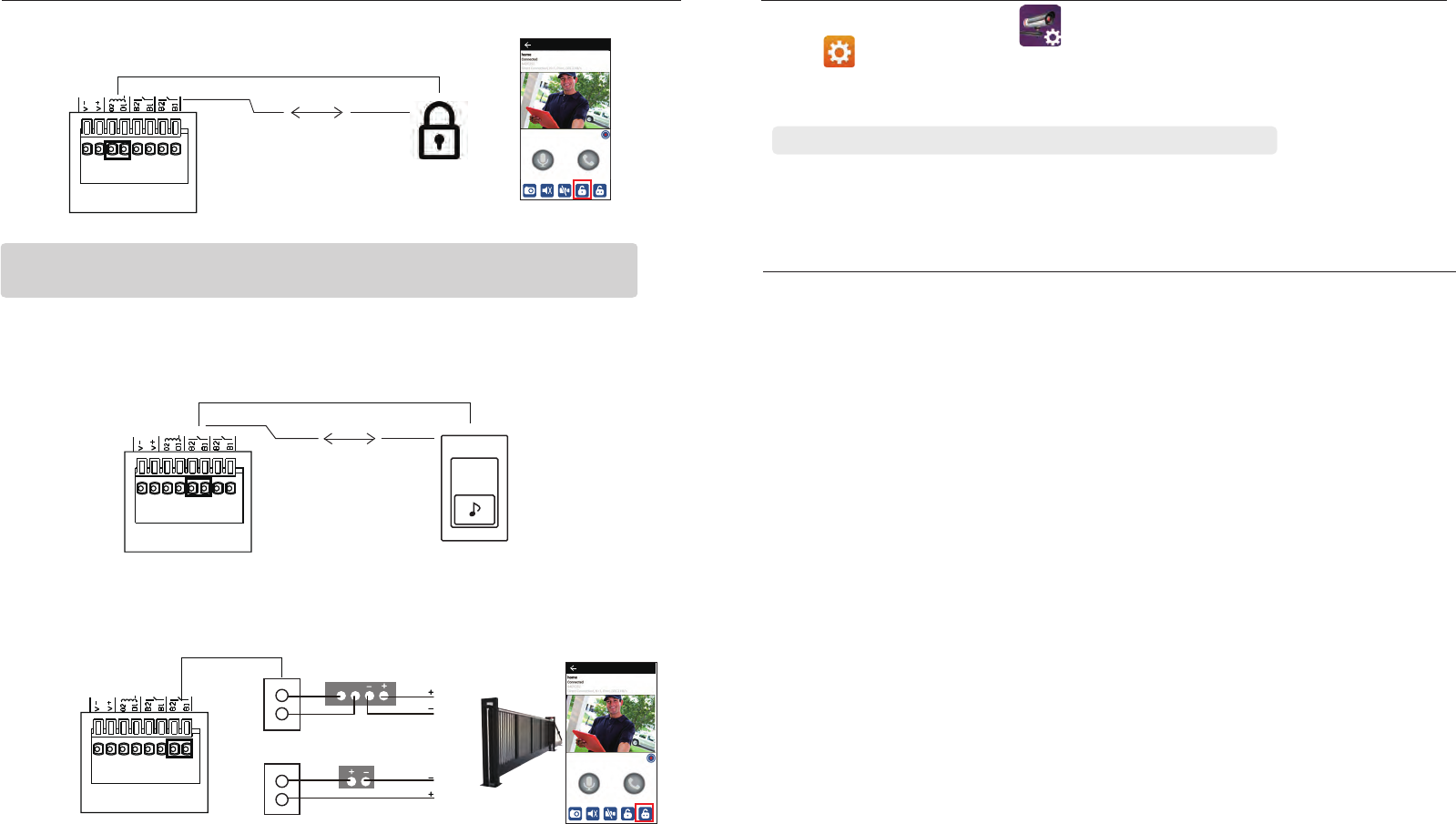
PLAYBACK
(1) Tap the Device Setting and then the Event List icon.
(2) Select the time interval for the event list.
(3) Tap to select the le for playback.
(4) If you want to store the le in mobile device, tap to download the le (best while
under Wi-Fi environment due to large high denition data size).
3rd Party Lock/Gate Control
Video On/O
Mute/Unmute
Snapshot
Live View
Main Page
ANSWERING A CALL
Above screen would appear When visitor
pressed the bell button.
1. Ignore the visitor call request.
2. Accept the visitor call request.
21
Note: For iOS user, due to the system fundamental structural design, you will have to
conrm/accept incoming visitor call request via pop-ups rst before the answering
section would appear. For more details, please refer to the manual.
Video Record
Phone Mode Talk
Live View
Hand-Free Talk
DEVICE SETTING TIPS
Please note this device supports operation using both batteries (AA battery x4) and power from existing
doorbell power lines (9V~36V AC/DC); however, there are certain function limitation when the device is
running under battery mode:
*Once the device is in sleep mode; the user can no longer access the device from their mobile
device. The device will only become online when the motion detector has detected an event,
or by pressing the power button at the bottom of the device.
Device will return to sleep mode after:
After device wakeup on visitor call or motion-detect event; the device will automatically goto sleep
mode again in any of the following conditions:
A. When preset power saving time (30s/60s/90/120s) is reached after a visitor or motion events
B. After user answer a visitor call or check live view from a motion-detect event using the APP and
then exit the APP.
C. When device cannot connect to the pre-set Wi-Fi network for any reason; the device will retry the
connection for 30 seconds, if Wi- connection still can not establish after 30 seconds, the reconnect
attempt will be stopped and the device will enter power saving mode again.
How to Maximized Battery Power:
When device is using battery power, we suggest using the following setting to maximize battery power
• Install the doorphone where it can receive excellent Wi-Fi network signals (Weak Wi-Fi signal will force
doorphone to operate using higher Wi-Fi Power, which may consume more power).
• Set Auto Sleep Timer to 30 seconds.
• Do not stay in live view or system setting mode unless it’s necessary.
(1) While in the device list section, tap to bring up edit option icons.
(2) Tap to enter System Info
(3) Select "Advanced" and enter default password: 123456.
(4) Scroll down to the Power Saving section and select desire power saving time.
Note: It is suggested to set the Power Saving to 30 seconds to maximize battery power.
POWER SAVING MODE
Note: For remote door unlock function with 12V/1A current output trigger, the direct input
power must be higher or equal to AC or DC 15V/1.5A.
ADDITIONAL WIRING DIAGRAMS
A. Electronic Lock
++
Lock
- -
C. Electronic Gate(2/4-Wire Type Connection)
Gate
4-WIRE TYPE CONNECTION DIAGRAM
2-WIRE TYPE CONNECTION DIAGRAM
Power
Input
Power
B2
B1
B2
B1
B. Existing Bell Wiring
- -
++
DoorBell
Live View
Live View
FCC Compliance Statement: This device complies with Part
15 of the FCC rules. Operation is subjected to the following
two conditions: (1)this device may not cause harmful
interference, and (2) this device must accept any
interferencereceived, including interference that may cause
undesired operation.
Products with CE Marking comply with EMC Directive
(2014/30/EU); Low Voltage Directive (2014/35/EU); RED
(2014/53/EU); ROHS Directive (2011/65/EU) issued by the
Commission of the European Community. Compliance
with these directives implies conformity to the following
European Norms:
EMC: EN 301 489
LVD: EN 60950
Radio: EN 300 328
If the camera system no longer functions or can no longer be repaired, it must be disposed of according to the valid statutory regulations.
Disposal of spent batteries/accumulators:
You are required by law (Battery Ordinance) to return all spent batteries and accumulators. Disposing of spent batteries/accumulators with
common household waste is prohibited! Batteries/accumulators that contain hazardous substances are marked with the symbols on the
side. These symbols indicate that it is prohibited to dispose of these batteries/accumulators in the household waste. The abbreviations for the
respective heavy metals are: Cd=cadmium, Hg=mercury, Pb=lead. You can return spent batteries and accumulators that can no longer be
charged to the designated collection points in your community, outlets or wherever batteries or accumulators are sold. Following these
FCC Statement
Changes or modifications not expressly approved by the party
responsible for compliance could void the user's authority to oper-
ate the equipment.
This equipment has been tested and found to comply with the limits
for a Class B digital device, pursuant to Part 15 of the FCC Rules.
These limits are designed to provide reasonable protection against
harmful interference in a residential installation. This equipment
generates uses and can radiate radio frequency energy and, if not
installed and used in accordance with the instructions, may cause
harmful interference to radio communications. However, there is no
guarantee that interference will not occur in a particular installation.
If this equipment does cause harmful interference to radio or televi-
sion reception, which can be determined by turning the equipment
off and on, the user is encouraged to try to correct the interference
by one or more of the following measures:
-- Reorient or relocate the receiving antenna.
-- Increase the separation between the equipment and receiver.
-- Connect the equipment into an outlet on a circuit different from
that to which the receiver is connected.
-- Consult the dealer or an experienced radio/TV technician for help
This device complies with part 15 of the FCC rules. Operation is
subject to the following two conditions (1)this device may not cause
harmful interference, and (2) this device must accept any interfer-
ence received, including interference that may cause undesired
operation.
The product from the body using the distance of not less than 20 cm