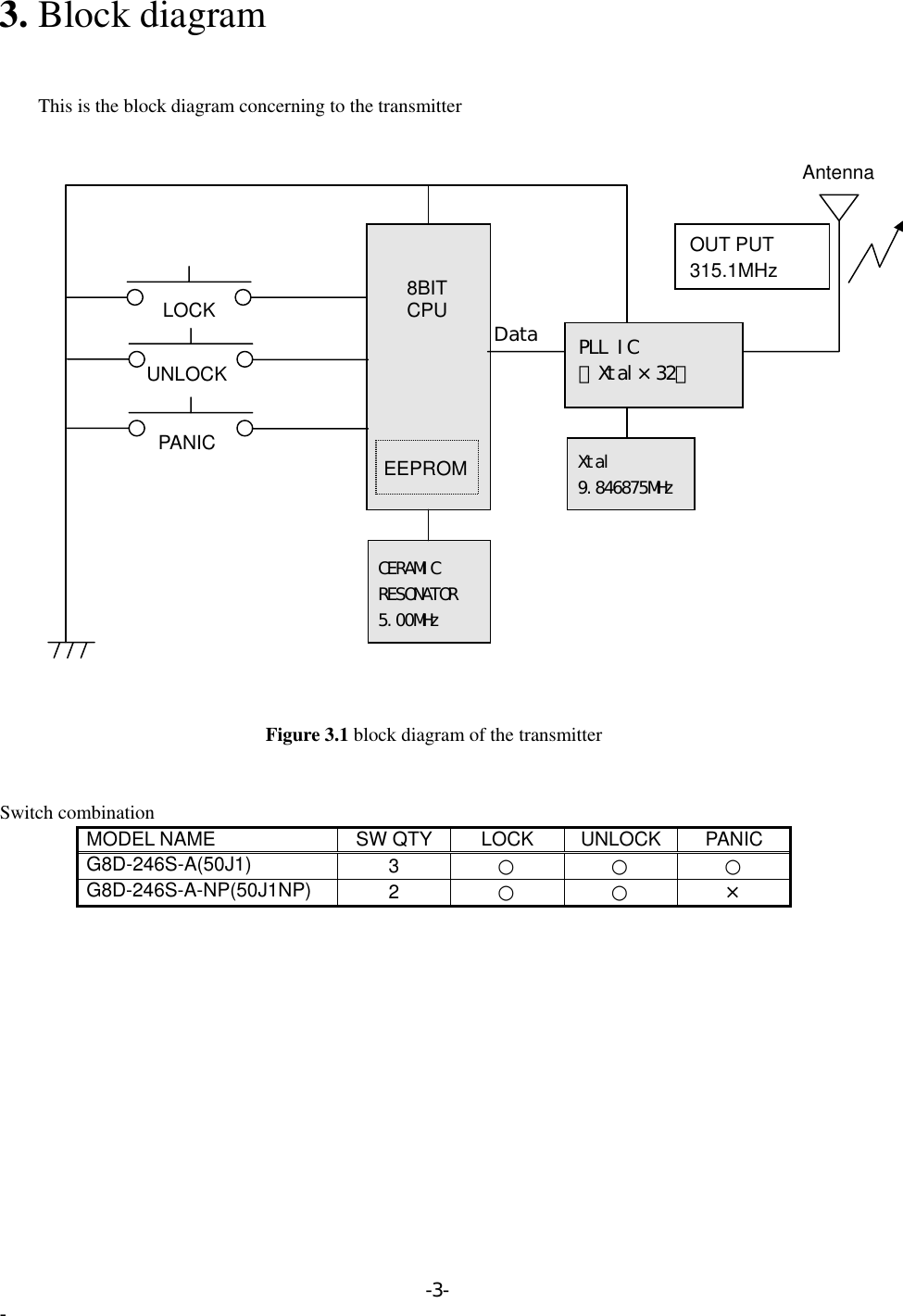
NIDEC MOBILITY G8D-246S-A Keyless Entry System (Transmitter) User Manual 50J1

OMRON Automotive Electronics Co. Ltd. Keyless Entry System (Transmitter) 50J1

Contents

User Manual

               50J1   Transmitter, RF Keyless Entry System    50J1NP
 Table of contents  1.  Constitution of the Radio Frequency Keyless Entry system with Door Lock   Controller for vehicle    ......................................................................................  12. User’s manual (provisionally)    ..........................................................................  23.  Block diagram  ................................................................................................  34.  Specification  ...................................................................................................  45.  Features  ..........................................................................................................  56. PCB 6.1.1    Circuit diagram  ...........................................................................................  66.2.1    Parts layout  (front).......................................................................................  76.2.2    Parts layout  (back).......................................................................................  86.3.1    Pattern layout  (front)...................................................................................  96.3.2    Pattern layout  (back)...................................................................................  106.4    Parts list  ......................................................................................................  11
1. Constitution of the Radio Frequency Keyless Entry       System with Door Lock Controller for vehicle       The radio frequency keyless entry is a system that it controls locking and unlocking the door by wireless remote controller. This system consists of two components. The TRANSMITTER is a device that transmits the signal when the button is pressed. The transmission signal consists of several synchronous codes, unique identification code, and security code and function code. The RECEIVER is fixed inside the vehicle. It works intermittently to prevent the battery exhaustion. When the receiver detects the synchronous code, it runs continuously to receive the signals completely. After receiving the signal, the receiver decides which operation will be performed. The user can select the following operations by pressing the button of the remote transmitter.  OPERATION ACTION LOCK  Lock the door UNLOCK  Unlock the door (the driver side first, then all doors) PANIC  MODE  Flush the light, flush the small light, and beep the horn. (it continues 30 seconds)  This receiver also controls wired operation. When the key is in the driver’s side key cylinder, all doors will Unlock if the key is turned to UNLOCK and hold more than one second. In case of the operation time is shorter, the only driver’s side door is mechanically unlocked. It is also available to control the door lock status by using the remote door control switch (both driver’s and passenger’s side).                       Transmitter f =315.1MHz -1- -
 2. User’s manual (provisionally)  REMOTE TRANSMITTER                                  You can lock and unlock your vehicle with the remote transmitter.  LOCK       When you push the LOCK button, all the doors will lock.         You cannot lock any of the doors with the remote transmitter if any door is open or the key is in the      ignition switch.  UNLOCK       When you push the UNLOCK button once , only the driver’s door unlocks. The remaining door unlock when you push the button a second time. If you unlock the doors with the remote transmitter, but do not open any of the doors within 30 seconds, the doors will automatically relocked. You cannot unlock any of the doors with the remote transmitter if the key is in the ignition switch.  PANIC MODE           Panic mode allows you to remotely sound your vehicle’s horn to attract attention. To activate this           mode , press and hold the PANIC button for about one seconds. Your vehicle’s horn will beep for about      30 seconds.           To cancel Panic mode before 30 seconds , press any button on the remote transmitter. You can also           turn the ignition switch is in ON. -2- -
3. Block diagram           This is the block diagram concerning to the transmitter  AntennaPLL IC (Xtal×32) LOCKUNLOCK CERAMIC RESONATOR 5.00MHz DataXtal 9.846875MHz EEPROMPANIC8BITCPUOUT PUT 315.1MHz  Figure 3.1 block diagram of the transmitter   Switch combination MODEL NAME  SW QTY  LOCK  UNLOCK PANIC G8D-246S-A(50J1)  3  ○ ○ ○ G8D-246S-A-NP(50J1NP)  2  ○ ○ ×  -3- -
4. Specification   4.1 CPU Type uPD789860 (8bit) Manufacturer: NEC Corporation ROM 4K bytes RAM 128 bytes EEPROM 16 bytes Clock frequency  5MHz Clock frequency generation  Ceramic resonator Package 20pin SOP  4.2 RF block Carrier frequency  315.1MHz Frequency generation  Crystal resonator   Modulation FSK Bit transmission rate  1000bps or 2000bps Bandwidth 120KHz RF output power (field strength)  10.8uW(6000μV/m)  at3m max  4.3 Others Dimension  55.7mm×33.8mm×11.8mm  Weight 18.0g Battery  Lithium cell (CR2032) Manufacturer: Maxell or Panasonic Operation Voltage  DC 3V, 220mAh Operation temperature  -20℃ ~ +60℃  -4- -
5. Features   5.1 Transmission frame         The transmission begins immediately in case of LOCK or UNLOCK button is pressed.         The transmission frame consists of the synchronous frame and the data frame. The synchronous frame has 81 synchronous codes that it will be used for the receiver to wake up. The data frame consists of 28-bit length identification code, 16-bit security code and function code. 1600 million different identification codes are available. The security code is always changed in case of any of the buttons is pressed. The transmission time is typically 370 milliseconds.          5.2 Battery saving         To prevent the battery exhaustion, the microcomputer of the transmitter is usually inactive. When the button will be pressed, the microcomputer wakes up immediately and judges which button is pressing. Then the microcomputer constructs the transmission frame and radiates it from the antenna. After transmitting, the microcomputer switches stand-by mode by itself. -5- -
6. PCB  6.1 Circuit diagram  Figure 6.1.1 Circuit diagrams -6- -
6.2 Parts layout  Figure 6.2.1 Parts layout (front)   -7- -
 Figure 6.2.2 Parts layout (back)  -8- -
6.3 Pattern layout                  Figure 6.3.1 Pattern layout (front) -9- -
                   Figure 6.3.2 pattern layout (back) -10- -
6.4 Parts List3C4,C716 MURATA 1 GRM36CG060B50PT 6pF   50V(±1%) C1115 MURATA 221SMT RESISTORSMT INDUCTOR 21*PANASONIC 2~3 EVQPL5A1516pinPLL ICTDA5101GEG1 GRM40F105Z16PTCSTCR5M00G53A-R0FCX-03 9.846875MHzRK10CAZ100J-T1GRM36B104K10PT112RK10CAZ33KJ-T1POZ2AN-1-501N-T00EXB28V333JXEXB24V333JXMANUFACTURE QTY MATERIAL/MODEL1FR4*NEC μPD789860MC1No1PARTS NAME121311104567RESISTOR ARRAYSMT RESISTOR11SMT RESISTOR11PANASONICPANASONIC*118Double SidedBoardCPU1PWBRESISTOR ARRAY3289REMARKSAPPEARANCE/SPECIFICATIONSSOPt=0.820pinCERAMIC RESONATORX TALSMT POTCPUIC120SMT RESISTOR141719SMT RESISTORCERAMIC CAPACITORCERAMIC CAPACITORTACT SWITCHCERAMIC CAPACITOR*L1-11-PANASONIC*MURATAMURATAERJ2GE0R00X2L2,L3±0.5%9.846875MHz33k ohm×4Resistors500 ohm1/16WR8C1,C3C2R6,C5RA1,RA2RA3R1R2,5,7RK10CAZ330KJ-T10 ohm5.00MHz(KEYLESS TRANSMITTER)G8D-246S-A-CHN   SHEET No (1/2)PARTS LIST33k ohm×2Resistors330k ohm   1/16W33k ohm   1/16W100 ohm1/16WCERAMIC CAPACITORCERAMIC CAPACITOR MURATAMURATAGRM36CG100B50PT0 ohmLQP11A82NG00INFINEONMURATARIVERMURATAGRM36CG050B50PTRK16CAY00-T1350gf0.1μF     10V1μF      16V10pF  50V(±1%)82nH5pF   50V(±1%)IC1CST1XTAL1VR1C8*1SW1,2,3
QTY3212-40252627Battery Terminal (+)Battery Terminal(-)ShoushinSeimitsu t=0.15t=0.15KNOB,LOCK/UNLOCK21Lithium Button Battery/SPECIFICATIONQTY32PARTS NAMECASE LOWERCASE, UPPER ASSY(2SW)PANASONICMANUFACTUREF-PLAS3922342838SEAL, RUBBER3637G8D-246S-A  SW1,2,3G8D-246S-A-NP  SW1,2(KEYLESS TRANSMITTER)PARTS LISTG8D-246S-A-CHN   SHEET No (2/2)CPMKEY RING293031353311 BLACKNo1 C5210R-HAPPEARANCEF-PLASABSABS1F-PLAS1DOUBLEINJECTIONCR2032ABS BLACK111 C5210R-HShoushinSeimitsuMATERIAL/MODELF-PLASREMARKSSILICONPBW NICKELPLATING※1.As for NO.20 , the number of use is different each model.MODEL NAME REMARKSIC2,JP1,JP2,R3,C6,C9,C10,SW3,SW4,ARE NOT MOUNTED

Navigation menu