NIDEC MOBILITY G8D-246S-A Keyless Entry System (Transmitter) User Manual 50J1
OMRON Automotive Electronics Co. Ltd. Keyless Entry System (Transmitter) 50J1
Contents
- 1. User Manual
- 2. Regulatory information
User Manual

50J1
Transmitter, RF Keyless Entry System
50J1NP
Table of contents
1. Constitution of the Radio Frequency Keyless Entry system with Door Lock
Controller for vehicle ...................................................................................... 1
2. User’s manual (provisionally) .......................................................................... 2
3. Block diagram ................................................................................................ 3
4. Specification ................................................................................................... 4
5. Features .......................................................................................................... 5
6. PCB
6.1.1 Circuit diagram ........................................................................................... 6
6.2.1 Parts layout (front)....................................................................................... 7
6.2.2 Parts layout (back)....................................................................................... 8
6.3.1 Pattern layout (front)................................................................................... 9
6.3.2 Pattern layout (back)................................................................................... 10
6.4 Parts list ...................................................................................................... 11

1. Constitution of the Radio Frequency Keyless Entry
System with Door Lock Controller for vehicle
The radio frequency keyless entry is a system that it controls locking and unlocking the door by
wireless remote controller. This system consists of two components. The TRANSMITTER is a device that
transmits the signal when the button is pressed. The transmission signal consists of several synchronous
codes, unique identification code, and security code and function code. The RECEIVER is fixed inside the
vehicle. It works intermittently to prevent the battery exhaustion. When the receiver detects the
synchronous code, it runs continuously to receive the signals completely. After receiving the signal, the
receiver decides which operation will be performed. The user can select the following operations by
pressing the button of the remote transmitter.
OPERATION ACTION
LOCK Lock the door
UNLOCK Unlock the door (the driver side first, then all doors)
PANIC MODE Flush the light, flush the small light, and beep the horn.
(it continues 30 seconds)
This receiver also controls wired operation. When the key is in the driver’s side key cylinder, all doors will
Unlock if the key is turned to UNLOCK and hold more than one second. In case of the operation time is shorter,
the only driver’s side door is mechanically unlocked. It is also available to control the door lock status by using
the remote door control switch (both driver’s and passenger’s side).
Transmitter
f =315.1MHz
-1-
-
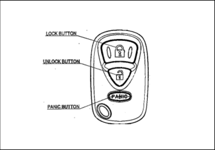
2. User’s manual (provisionally)
REMOTE TRANSMITTER
You can lock and unlock your vehicle with the remote transmitter.
LOCK
When you push the LOCK button, all the doors will lock.
You cannot lock any of the doors with the remote transmitter if any door is open or the key is in the
ignition switch.
UNLOCK
When you push the UNLOCK button once , only the driver’s door unlocks. The remaining door unlock
when you push the button a second time. If you unlock the doors with the remote transmitter, but do not open
any of the doors within 30 seconds, the doors will automatically relocked.
You cannot unlock any of the doors with the remote transmitter if the key is in the ignition switch.
PANIC MODE
Panic mode allows you to remotely sound your vehicle’s horn to attract attention. To activate this
mode , press and hold the PANIC button for about one seconds. Your vehicle’s horn will beep for about
30 seconds.
To cancel Panic mode before 30 seconds , press any button on the remote transmitter. You can also
turn the ignition switch is in ON.
-2-
-
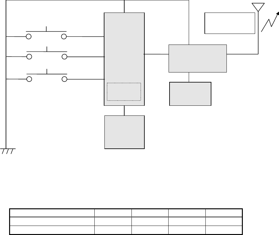
3. Block diagram
This is the block diagram concerning to the transmitter
Antenna
PLL IC
(Xtal×32)
LOCK
UNLOCK
CERAMIC
RESONATOR
5.00MHz
Data
Xtal
9.846875MHz
EEPROM
PANIC
8BIT
CPU
OUT PUT
315.1MHz
Figure 3.1 block diagram of the transmitter
Switch combination
MODEL NAME SW QTY LOCK UNLOCK PANIC
G8D-246S-A(50J1) 3 ○ ○ ○
G8D-246S-A-NP(50J1NP) 2 ○ ○ ×
-3-
-

4. Specification
4.1 CPU
Type uPD789860 (8bit)
Manufacturer: NEC Corporation
ROM 4K bytes
RAM 128 bytes
EEPROM 16 bytes
Clock frequency 5MHz
Clock frequency generation Ceramic resonator
Package 20pin SOP
4.2 RF block
Carrier frequency 315.1MHz
Frequency generation Crystal resonator
Modulation FSK
Bit transmission rate 1000bps or 2000bps
Bandwidth 120KHz
RF output power (field strength) 10.8uW(6000μV/m) at3m max
4.3 Others
Dimension 55.7mm×33.8mm×11.8mm
Weight 18.0g
Battery Lithium cell (CR2032)
Manufacturer: Maxell or Panasonic
Operation Voltage DC 3V, 220mAh
Operation temperature -20℃ ~ +60℃
-4-
-
5. Features
5.1 Transmission frame
The transmission begins immediately in case of LOCK or UNLOCK button is pressed.
The transmission frame consists of the synchronous frame and the data frame. The synchronous frame
has 81 synchronous codes that it will be used for the receiver to wake up. The data frame consists of 28-bit
length identification code, 16-bit security code and function code. 1600 million different identification
codes are available. The security code is always changed in case of any of the buttons is pressed. The
transmission time is typically 370 milliseconds.
5.2 Battery saving
To prevent the battery exhaustion, the microcomputer of the transmitter is usually inactive. When the
button will be pressed, the microcomputer wakes up immediately and judges which button is pressing.
Then the microcomputer constructs the transmission frame and radiates it from the antenna. After
transmitting, the microcomputer switches stand-by mode by itself.
-5-
-
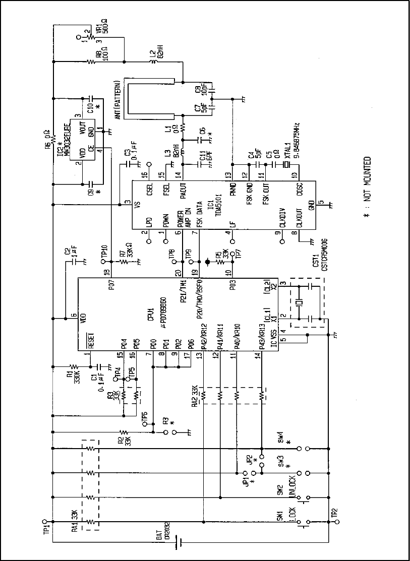
6. PCB
6.1 Circuit diagram
Figure 6.1.1 Circuit diagrams
-6-
-
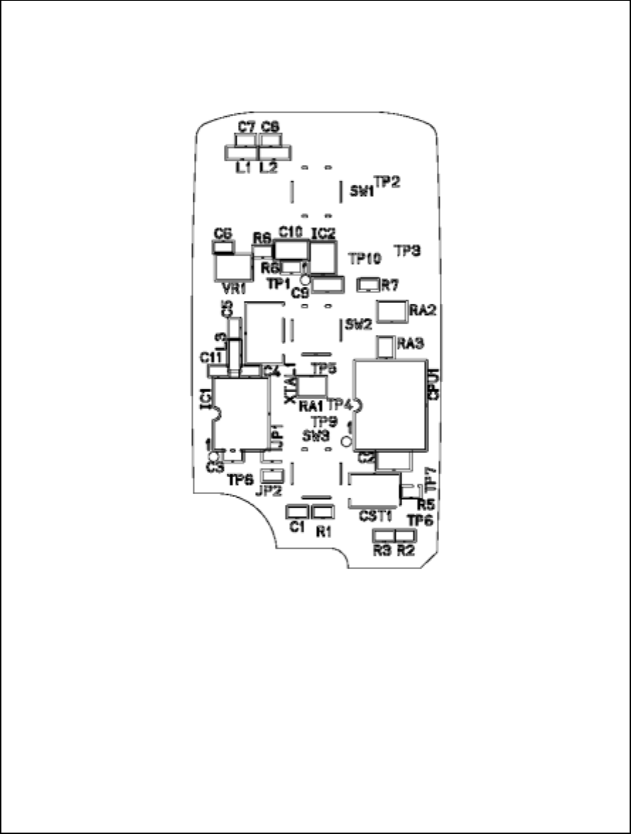
6.2 Parts layout
Figure 6.2.1 Parts layout (front)
-7-
-
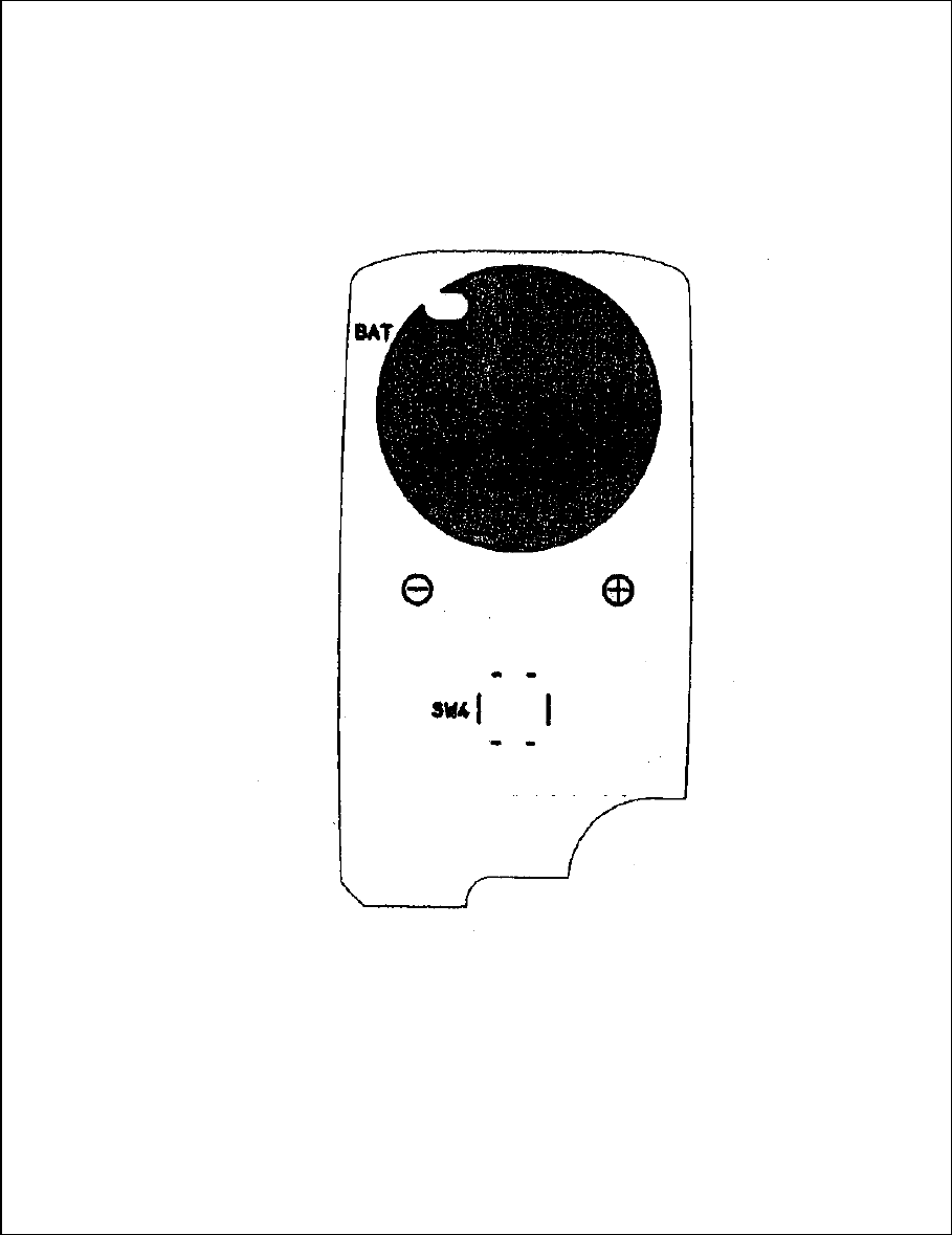
Figure 6.2.2 Parts layout (back)
-8-
-
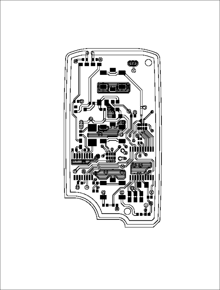
6.3 Pattern layout
Figure 6.3.1 Pattern layout (front)
-9-
-
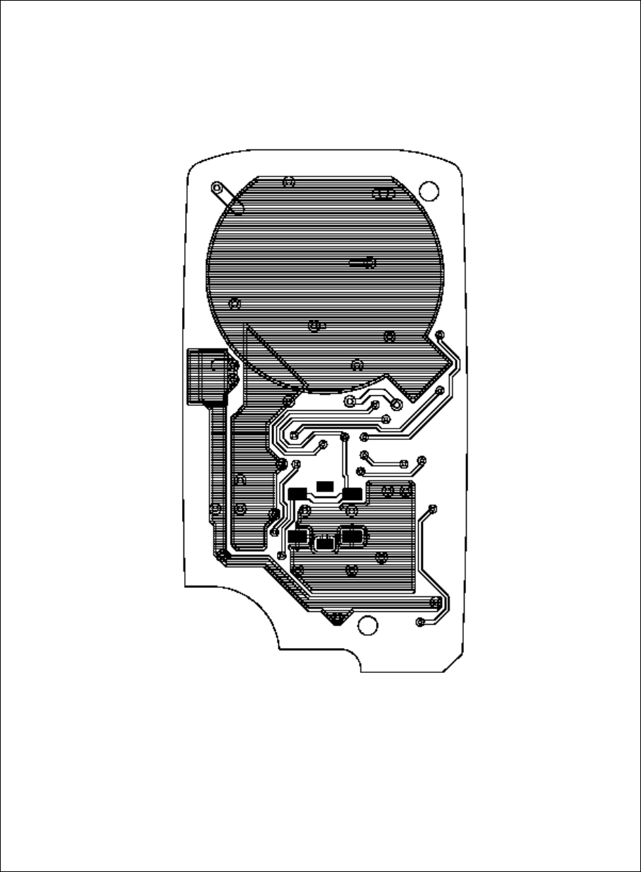
Figure 6.3.2 pattern layout (back)
-10-
-

6.4 Parts List
3
C4,C7
16 MURATA 1 GRM36CG060B50PT 6pF 50V(±1%) C11
15 MURATA 2
2
1
SMT RESISTOR
SMT INDUCTOR 2
1
*
PANASONIC 2~3 EVQPL5A15
1
6p
in
PLL I
C
TDA5101GEG
1 GRM40F105Z16PT
CSTCR5M00G53A-R0
FCX-03 9.846875MHz
RK10CAZ100J-T1
GRM36B104K10PT
1
1
2
RK10CAZ33KJ-T1
POZ2AN-1-501N-T00
EXB28V333JX
EXB24V333JX
MANUFACTURE QTY MATERIAL/MODEL
1
FR4
*
NEC μPD789860MC
1
No
1
PARTS NAME
12
13
11
10
4
5
6
7
RESISTOR ARRAY
SMT RESISTOR
1
1SMT RESISTOR
1
1
PANASONIC
PANASONIC
*
1
18
Double Sided
Board
CPU1
PWB
RESISTOR ARRAY
3
2
8
9
REMARKS
APPEARANCE
/SPECIFICATION
SSO
P
t=0.8
2
0p
in
CERAMIC RESONATOR
X TAL
SMT POT
CPU
IC1
20
SMT RESISTOR
14
17
19
SMT RESISTOR
CERAMIC CAPACITOR
CERAMIC CAPACITOR
TACT SWITCH
CERAMIC CAPACITOR
*
L1
-11-
PANASONIC
*
MURATA
MURATA
ERJ2GE0R00X
2
L2,L3
±
0.5%
9.846875MHz
33k ohm×4
Resistors
500 ohm
1/16W
R8
C1,C3
C2
R6,C5
RA1,RA2
RA3
R1
R2,5,7
RK10CAZ330KJ-T1
0 ohm
5.00
MHz
(
KEYLESS TRANSMITTER
)
G8D-246S-A-CHN SHEET No
(
1/2
)
PARTS LIST
33k ohm×2
Resistors
330k ohm 1/16W
33k ohm 1/16W
100 ohm
1/16W
CERAMIC CAPACITOR
CERAMIC CAPACITOR MURATA
MURATA
GRM36CG100B50PT
0 ohm
LQP11A82NG00
INFINEON
MURATA
RIVER
MURATA
GRM36CG050B50PT
RK16CAY00-T1
350gf
0.1μF 10V
1μF 16V
10pF 50V(±1%)
82nH
5pF 50V(±1%)
IC1
CST1
XTAL1
VR1
C8
*1
SW1,2,3

Q
TY
3
2
12-
40
25
26
27
Battery Terminal (+)
Battery Terminal(-)
Shoushin
Seimitsu t=0.15
t=0.15
KNOB,LOCK/UNLOCK
21
Lithium Button Battery
/SPECIFICATION
QTY
32
PARTS NAME
CASE LOWER
CASE, UPPER ASSY
(2SW)
PANASONIC
MANUFACTURE
F-PLAS
39
22
34
28
38
SEAL, RUBBER
36
37
G8D-246S-A SW1,2,3
G8D-246S-A-NP SW1,2
(
KEYLESS TRANSMITTER
)
PARTS LIST
G8D-246S-A-CHN SHEET No
(
2/2
)
CPMKEY RING
29
30
31
35
33
1
1 BLACK
No
1 C5210R-H
APPEARANCE
F-PLAS
ABS
ABS
1
F-PLAS
1
DOUBLE
INJECTION
CR2032
ABS BLACK1
1
1 C5210R-H
Shoushin
Seimitsu
MATERIAL/MODEL
F-PLAS
REMARKS
SILICON
PBW NICKEL
PLATING
※1.As for NO.20 , the number of use is different each model.
MODEL NAME REMARKS
IC2,JP1,JP2,R3,C6,C9,C10,SW3,SW4,ARE NOT MOUNTED