NIDEC MOBILITY G8D-365M Tire Pressure Monitor Receiver User Manual 1

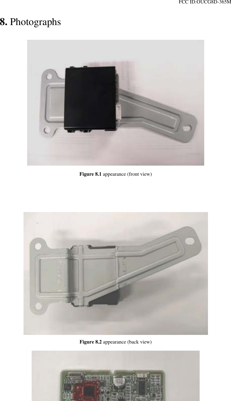
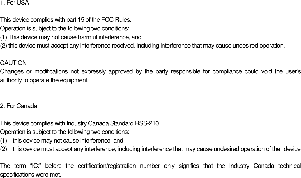
OMRON Automotive Electronics Co. Ltd. Tire Pressure Monitor Receiver 1

User Manual

 FCC ID:OUCG8D-365M                  G8D-365M   Receiver, Tire Pressure Monitoring System
 FCC ID:OUCG8D-365M    Table of contents  1.  Constitution of the Tire Pressure Monitoring System for vehicle.......................  2 2. User’s manual (provisionally)    ..........................................................................  3 3.  Block diagram  ................................................................................................  4 4.  Specification  ...................................................................................................  5 5.  Features  ..........................................................................................................  6 6. PCB     6.1    Circuit diagram  ...........................................................................................  7   6.2    Parts layout  (front)......................................................................................  8   6.3    Pattern layout  (front)....................................................................................  9   6.4    Parts layout  (back)....................................................................................  10   6.4    Pattern layout  (back)....................................................................................  11   6.5    Parts list  ......................................................................................................  12 7.  Connector  ..................................................…................................................. 16 8.  Photographs  ....................................................................................................  17                            - 1 -
 FCC ID:OUCG8D-365M   1. Constitution of the Tire Pressure Monitoring System for vehicle     Tire Pressure Monitoring System is the system that receives the information, from transmitters installed at each tire, about the inflation pressure or temperature of tires detected by the sensor, so that the system can detect the abnormality of tires like fallen inflation pressure. This system consists of transmitter, receiving antenna, and receiver. The transmitter sends information of tire, read by the sensor, in the form of radio wave at constant intervals. The receiver is fixed inside the vehicle. If IG is OFF, it works intermittently to prevent the battery exhaustion. When the receiver detects the synchronous code and IG is ON, it runs continuously to receive the signals completely. If the received code is normal, the system will not inform the user. As shown below, in the case that the transmitter sends information that the tire is in abnormal condition, and that the receiver system has a trouble, the system will inform the user with lighting up Warning bulb.  TPMS Warning bulb is lit by the following situations. Bulb disconnection detection output(The warning light is On for 3 sec. when IG=OFF→ON) Tire air pressure warning output (Warning light is ON) System warning output (Warning light is blinking)  Pressure sensor 1 CPU Receiving circuit CPU EEPROM Transmission circuit ReceiverTransmitter 1  AntennaTransmitter SP Transmitter 2 Transmitter 3 Transmitter 4 Tire Bulb                    Figure 2-1 System Architecture - 2 -
 FCC ID:OUCG8D-365M   2. User’s manual (provisionally)  METER PANELWarning light              Tire inflation pressure warning light   This light illuminates if the inflation pressure of any tire (except for compact spare tire) drops while the ignition key is in the “ON” position. It normally illuminates when the ignition key is turned to the “ON” position and goes off a few seconds later.  If the warning light illuminates while driving Avoiding hard braking, hard steering, and high speeds, drive to the nearest gas station or authorize car dealer and adjust the tire inflation pressures.(except for compact spare tire)  If the warning light blinking while driving It is thought abnormality of the device, go to the check to the nearest car dealer as soon as possible.  Whenever the tires and wheels are replaced with new ones     Tire inflation pressure sensors must be fitted on the new wheels and their ID codes must be programmed into the system. Have tire and wheel replacement performed by an authorized car dealer to avoid the risk of damaging the tire inflation pressure sensors.  CAUTION ・  If the tire inflation pressure warning-light does not illuminate when the ignition key is turned to the “ON” position the system may be faulty. ・  If the tire inflation pressure warning light illuminates while you are driving, avoid hard braking, hard steering, and high speeds. Otherwise, you could make the vehicle unstable and have a serious accident. ・  The tire inflation pressure warning light may not illuminate immediately in the event of a tire blowout or rapid leak..   - 3 -
 FCC ID:OUCG8D-365M   3. Block diagram           This is the block diagram concerning to the receiver.  16BIT CPURECEIVING MODULE EEPROM POWER SOURCE(5V) dataOUTPUT CIRCUIT Signal of vehicle status inputoutput12V (car battery)     IG1  bulb         Figure 3.1 block diagram of the receiver         - 4 -
 FCC ID:OUCG8D-365M   4. Specification   4.1 CPU Type M30102(16bit) Manufacturer: MITSUBISHI ROM 24K bytes RAM 1Kytes Clock frequency  8.00MHz Clock frequency generation  Crystal oscillator Package 48pin QFP  4.2 RF block Local clock frequency  325.7MHz Frequency generation  Crystal resonator Modulation Single Superheterodyne Bandwidth  ±200KHz Sensitivity 30dBuV  4.3 Others Dimension   83mm×64mm×31mm Weight  120g Battery  Car Battery (DC 12V) Operation Voltage  DC 12V, 20mA Operation temperature  -30℃ ~ +80℃                - 5 -
 FCC ID:OUCG8D-365M   5. Features   Battery saving     The receiver works intermittently to reduce the battery consumption. The microcomupter embedded on the receiver controlls the power supply for the RF circuit. In case of the microcomputer detects the wake-up signal during the power supplied, the microcomputer continue supplying the power until the data frame will be received.                   - 6 -
 FCC ID:OUCG8D-365M   6. PCB 6.1 Circuit diagram                                       Figure 6.1 Circuit diagrams - 7 -
 FCC ID:OUCG8D-365M   6.2 Parts layout (front)    Figure 6.2 Parts layout (front) - 8 -
 FCC ID:OUCG8D-365M   6.3 Pattern layout (front)       Figure 6.3  Pattern layout (front) - 9 -
 FCC ID:OUCG8D-365M   6.4 Parts layout (back)      - 10 -
 FCC ID:OUCG8D-365M   6.5 Pattern layout (back)      Figure 6.4  pattern layout (back) - 11 -
 FCC ID:OUCG8D-365M   6.6 Parts List № PART NAME MANUFACTURE QTY TYPE  SPECIFICATION  REMARKS 1 CPU  Mitsubishi  1 M30102F3TFP     CPU1 2  Regulator IC  SEIKO Ins  1 S-875039BUP-ABD-T2     IC1 3  EEPROM IC  SEIKO Ins  1 S-93C66AMFN-TB  4K  IC5 4 OP-AMP  TOSHIBA  1 TC75S55FU-TE85L     IC4 5 Reception IC  Infinion technologies  1 TDA5211GEG    IC3 6 Reset IC  Mitsumi  1 MM1185AFFE     IC2 7 Resistor array   KOA  4 CN1J4TTD473J  47k  RA1,RA2,RA3,RA48 Chip resistor  *  5 RK16CAY100J-T1  100  R106,R101,R102, R103,R105 9 Chip resistor  *  6 RK16CAY100KJ-T1  100k  R104,R110,R115, R117,R122,R123 10 Chip resistor  *  2 RK16CAY10KJ-T1  10k  R12,R25 11 Chip resistor  *  1 RK16CAY160KJ-T1  160k  R14 12 Chip resistor  *  4 RK16CAY1KJ-T1  1k  R108,R109,R113, R114 13 Chip resistor  *  1 RK16CAY1MJ-T1  1M  R121 14 Chip resistor  *  1 RK16CAY15KJ-T1  15k  R15 15 Chip resistor  *  2 RK16CAY22KJ-T1  22k  R4,R26 16 Chip resistor  Matsushita  1 ERJ3EKF3303V 330k  R118 17 Chip resistor  *  1 RK16CAY39KJ-T1  39k  R111 18 Chip resistor  *  1 RK16CAY4.7KJ-T1  4.7k  R9 19 Chip resistor  *  2 RK16CAY470KJ-T1  470k  R35,R120 20 Chip resistor  *  11 RK16CAY47KJ-T1  47k  R3,R5,R11,R19,R20,R21,R22,R23,R37, R49,R58 21 Chip resistor  *  2 RK16CAY5.1KJ-T1  5.1k  R45,R107 22 Chip resistor  *  1 RK16CAY5.6KJ-T1  5.6k  R50 23 Chip resistor  *  1 RK16CAY560KJ-T1  560k  R112 - 12 -
 FCC ID:OUCG8D-365M   № PART NAME MANUFACTURE QTY TYPE  SPECIFICATION  REMARKS 24 Chip resistor  *  1 RK16CAY75KJ-T1  75k  R36 25 Chip resistor  *  1 RK16CAY820KJ-T1  820k  R116 26 Chip resistor  *  1 RK32CAY1.5KJ-T1  1.5k  R6 27 Chip resistor  *  2 RK32CAY22KJ-T1  22k  R55,R56 28 Chip resistor  *  4 RK32CAY390J-T1  390  R51,R52,R53,R54 29  Multi-layer ceramiccapacitor   Murata 1 GRK39CH101J50PT 100p C14 30  Multi-layer ceramiccapacitor   Murata 1 GRK39CH221J50PT 220p C126 31  Multi-layer ceramiccapacitor   Murata 2 GRK39CH270J50PT 27p C133,C134 32  Multi-layer ceramiccapacitor   Murata 4 GRK39R103K50PT 0.01u C112,118,119,C121 33  Multi-layer ceramiccapacitor   Murata 2 GRK39CH471J50PT 470p C18,C128 34  Multi-layer ceramiccapacitor   Murata 4 GRK39CH040C50PT 4p C101,C102,C103, C104, 35  Multi-layer ceramiccapacitor   Murata 4 GRK39CH080D50PT 8p C105,C106,C107, C108 36  Multi-layer ceramiccapacitor   Murata 2 GRK39CH220J50PT 22p C12,C13 37  Multi-layer ceramiccapacitor   Murata 9 GRK39R102K50PT 1000p C6,C15,C17,C22,C24C116,C117,C120, C130 38  Multi-layer ceramiccapacitor   Murata 2 GRK40R104K50PT 0.1u C2,C3 39  Multi-layer ceramiccapacitor   Murata 8 GRK39R104K16PT 0.1u C4,C5,C8,C9,C19, C20,C122,C127 40  Multi-layer ceramiccapacitor   Murata 1 GRK39R223K50PT 0.022u C11 41  Multi-layer ceramiccapacitor   Murata 2 GRK39R473K25PT 0.047u C129,C131 42  Multi-layer ceramiccapacitor   Murata 1 GRK39R683K16PT 0.068u C16 43  Multi-layer ceramiccapacitor   Murata 1 GRK39R472K50PT 4700p C125 44  Electrolytic capacitor  Nihon Chemikon  1 MVA35VC100MF80  100U  C1 45  Electrolytic capacitor  Nihon Chemikon  1 MVA16VC470MH10  470U  C7 46 Diode  Rohm  2 1SS355TE-17    D4,D7 47 Diode  Shindengen  1 D1F60-4063    D1 - 13 -
 FCC ID:OUCG8D-365M   № PART NAME MANUFACTURE QTY TYPE  SPECIFICATION  REMARKS 48 Diode  Rohm  1 DAN202UT106    D5 49 Diode  Shindengen  1 M1F60-4063    D3 50 Transistor  Sanyo  1 2SC3651-TD    TR1 51 Transistor  Rohm  1 2SD1834T100    TR9 52 Digital transistor  Rohm  2 DTA114EUAT106    TR3,TR5 53 Digital transistor  Rohm  1 DTA114YUAT106    TR8 54 Digital transistor  Rohm  2 DTC114EUAT106    TR6,TR102 55 Digital transistor  Rohm  1 DTC123EUAT106    TR4 56 Transistor  NEC  1 uPA801T-T1    TR101 57 Zener diode  ONSEMICONDUCTOR  2 MMSZ4689-T1   ZD2,ZD7 58 Zener diode  ONSEMICONDUCTOR  1 MMSZ4704-T1   ZD1 59 Zener diode  ONSEMICONDUCTOR  2 MMSZ5252B-T1   ZD3,ZD5 60  SAW filter  Seiko Epson  1 FF-585  315MHZ  F101 61 Ceramic filter  Murata  1 SFECV10M7DF00-R0    F102 62 Inductor  Murata  2 LQP11A33NG00  33n  L107,L108 63 Inductor  Murata  7 LQP11A68NG00  68n  L101,L102.L103, L104,L105,L106, L110 64 Ferrite beads  Murata  1 BLM11A102SPT    L1 65  Crystal oscillator  Japan Radio  1 AT-51CD2  (8.00MHZ)  XT2 66  Crystal oscillator  Japan Radio 1 AT-51CD2  (10.176MHZ) XT1 67 Connector  Yazaki  1 7382-5668    CN1 68 Connector  Hirose  1 GT13-1/1/1/1P-DS  4p  CN2 69 Connector  Molex  1 53307-1091  10p  CN3 70 Tapping screw    2 SWCH MFSN-PB  M3×6  Screw for CN1 71 PWB    1 CEM3     - 14 -
 FCC ID:OUCG8D-365M   № PART NAME MANUFACTURE QTY TYPE  SPECIFICATION  REMARKS 72 Label    1      73 Case    1      74  Cover   1     75 Bracket    1 SECC     76  ELEP coat           77 Chip resistor  *  1 RK16CAY00-T1  0  C109 78  Multi-layer ceramiccapacitor   Murata 1 GRK39CH060D50 6p C111 79  Multi-layer ceramiccapacitor   Murata 1 GRK39CJ030C50 3p C114 80 Chip resistor  Matsushita  1 ERJ6GEYJ473V  47k  R7 81 Chip resistor  Matsushita  1 ERJ3EKF1603V  160k  R119  - 15 -
 FCC ID:OUCG8D-365M   7. Connector          This is the pin assignment of the connector. No.  I/O  Assignment  Memorandum 1 INPUT Battery  12V 2 INPUT  TEST MODE  Active High 3 INPUT Velocity Signal   4  (not used)   5 IN/OUT   K-line Communication Line 6 INPUT  Ignition switch  Active High 7  (not used)   8  (not used)   9 OUTPUT Indicator  Active Low 10   Ground  GND - 16 -
 FCC ID:OUCG8D-365M   8. Photographs            Figure 8.1 appearance (front view)              Figure 8.2 appearance (back view)  - 17 -
 FCC ID:OUCG8D-365M             Figure 8.3 PCB assy (front view)               Figure 8.4 PCB assy (back view) - 18 -
1. For USA  This device complies with part 15 of the FCC Rules. Operation is subject to the following two conditions:   (1) This device may not cause harmful interference, and   (2) this device must accept any interference received, including interference that may cause undesired operation.  CAUTION Changes or modifications not expressly approved by the party responsible for compliance could void the user’s authority to operate the equipment.   2. For Canada  This device complies with Industry Canada Standard RSS-210. Operation is subject to the following two conditions: (1)  this device may not cause interference, and (2)  this device must accept any interference, including interference that may cause undesired operation of the   device  The term “IC:” before the certification/registration  number only signifies that the Industry Canada technical specifications were met.

Navigation menu