NINGBO DOOYA MECHANIC and ELECTRONIC TECHNOLOGY DC6010 Emitter User Manual DC1660DC1662 A 01
NINGBO DOOYA MECHANIC & ELECTRONIC TECHNOLOGY CO., LTD. Emitter DC1660DC1662 A 01
User Manual
Technical support
T
Fucntion instructionTechnical specification
Input voltage:3V(CR2430)
Transmitting frequency:433MHz
Transmitting power:10 milliwatt
Operating temperature:-100C—500C
Transmssion distance:200 meters open office,
35 meters on two walls
CAUTION
RISK OF EXPLOSION IF BATTERY IS REPLACED
BY AN INCORRECT TYPE.
DISPOSE OF USED BATTERIES ACCORDING
TO THE INSTRUCTIONS
Notice: transmitter do not exposed to moisture and strike, so as not to
affect life.When you use transmitter, if found emission distance obviously
short or less sensitive, please change another same new battery. Please
have batteries for recycling.
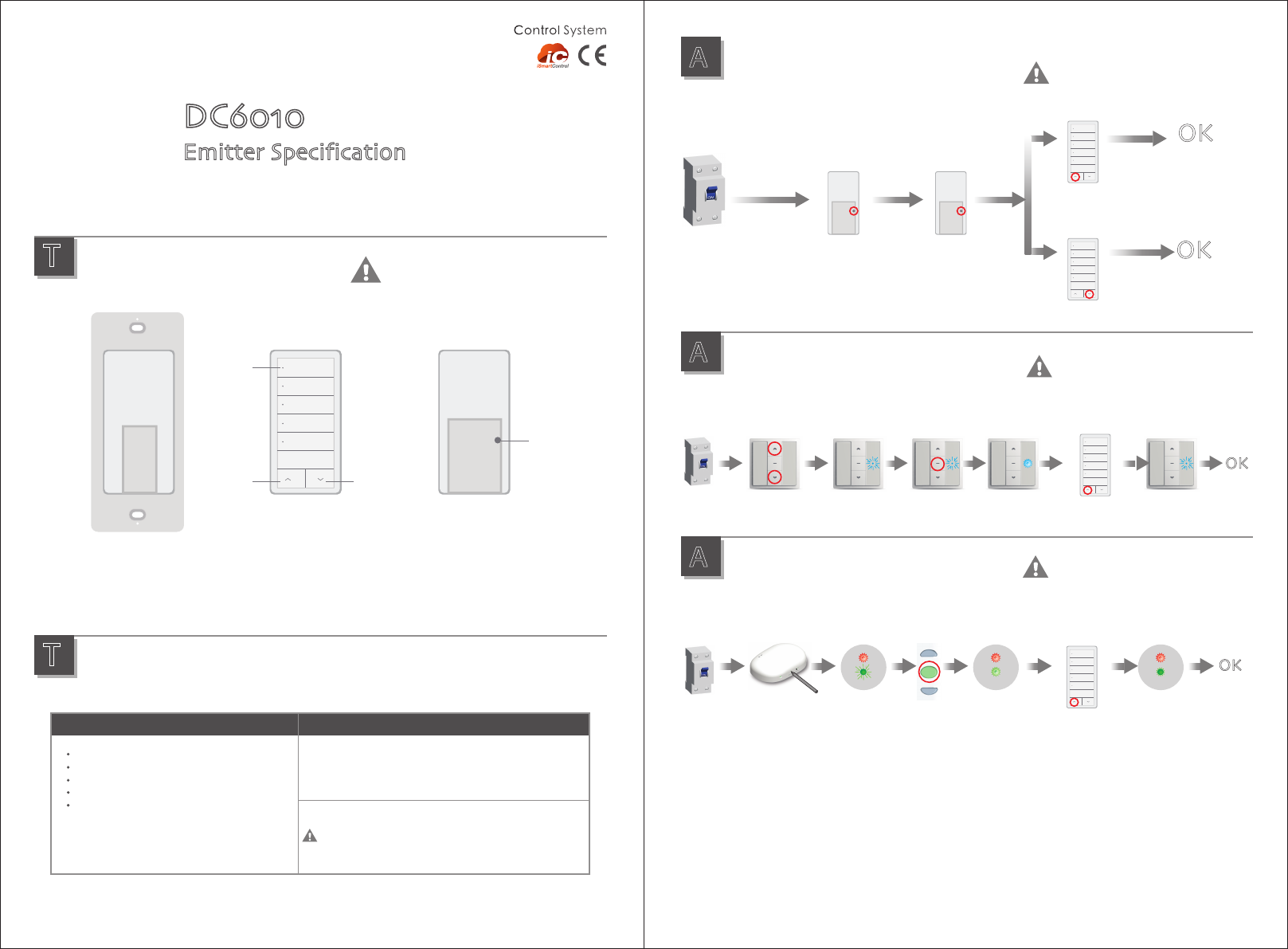
During the settings,the time between
two operation must be shorter than
4s,otherwise it will quit the setting
A
Additional
function
A
Additional
function
Matchable R tubular motor setting up
A
Additional
function
Matchable DC1680 setting up
Matchable DC136 setting up
Power on
Sound from motor
hear long sound
Power on
Power on
Press (up+down)×1
at the same time
Indicator
flashing
Indicator long
flashing
Indicator flashing
then extinguished
Setting
is ok
Setting
is ok
During the settings,the time between
two operation must be shorter than
6s,otherwise it will quit the setting
During the settings,the time between
two operation must be shorter than
10s,otherwise it will quit the setting
Up×1
Down×1
OK
OK
Delete all the datas of the motor and
the new emitter has been programmed.
Beep once Beep once
Set up is ok.
The up button control
the motor clockwise
Set up is ok.
The down button control
the motor clockwise
Setting button×1
OK
DC136 DC136 DC136 DC136 DC136
Stop×1
OK
DC1680 DC1680 DC1680 DC1680 DC1680
Indicator
flashing
Indicator long
flashing
Indicator flashing
then extinguished
Stop×1Up×1
Run or beep
for hint
Run or beep
for hint
Up×1
P2×1 P2×1
Type specification
T
Version NO. : A/00
5-channel emitter
DC6010 is 5-channel emitter,red light represents the currently selected
channel, press the current channel again, cancel selected channel,
when all the red light is bright, on behalf of the group control state.
Press stop, up, down key when the red light fast flash tips.
DC6010
Emitter Specification
BackBracket
1
2
3
4
5
STOP
LED
Channel
selection
}
1
2
3
4
5
STOP
1
2
3
4
5
STOP
1
2
3
4
5
STOP
1
2
3
4
5
STOP
Up button Down button
When you press the Setting button, the
required use of tools,don’t be too sharp tool.
Setting
button
(P2)
FCC STATEMENT
1. This device complies with Part 15 of the FCC Rules. Operation is subject to the following two
conditions:
(1) This device may not cause harmful interference.
(2) This device must accept any interference received, including interference that may cause
undesired operation.
2. Changes or modifications not expressly approved by the party responsible for compliance could
void the user's authority to operate the equipment.
NOTE: This equipment has been tested and found to comply with the limits for a Class B digital
device, pursuant to Part 15 of the FCC Rules. These limits are designed to provide reasonable
protection against harmful interference in a residential installation.
This equipment generates uses and can radiate radio frequency energy and, if not installed and
used in accordance with the instructions, may cause harmful interference to radio communications.
However, there is no guarantee that interference will not occur in a particular installation. If this
equipment does cause harmful interference to radio or television reception, which can be
determined by turning the equipment off and on, the user is encouraged to try to correct the
interference by one or more of the following measures:
Reorient or relocate the receiving antenna.
Increase the separation between the equipment and receiver.
Connect the equipment into an outlet on a circuit different from that to which the receiver is
connected.
Consult the dealer or an experienced radio/TV technician for help.