NMB Technologies 3900 RF Keyboard with Integrated Pointing Device User Manual NMB TECHNOLOGIES user guide
NMB Technologies Corp. RF Keyboard with Integrated Pointing Device NMB TECHNOLOGIES user guide
UserManual.wiki
>
NMB Technologies
>
3900 User Manual
users manual
Navigation menu
Upload a User Manual
Namespaces
Wiki Guide
HTML
PDF
Info
Views
User Manual
Discussion / Help
Navigation
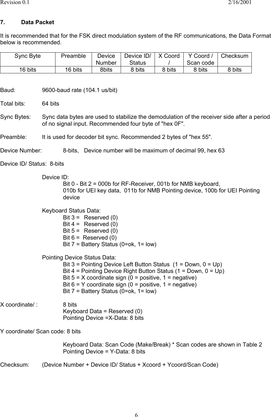
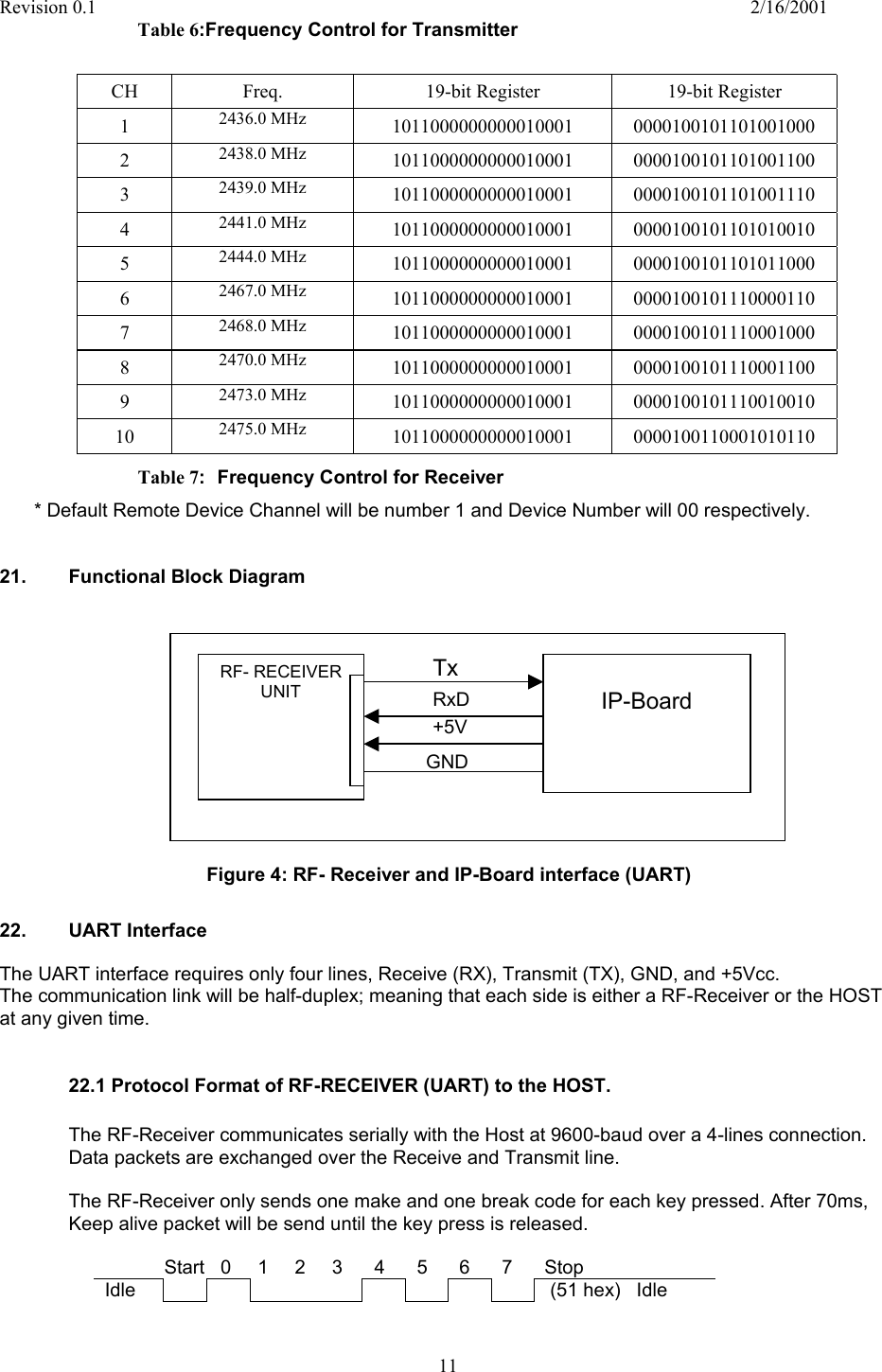
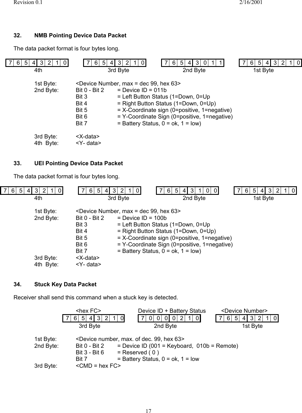

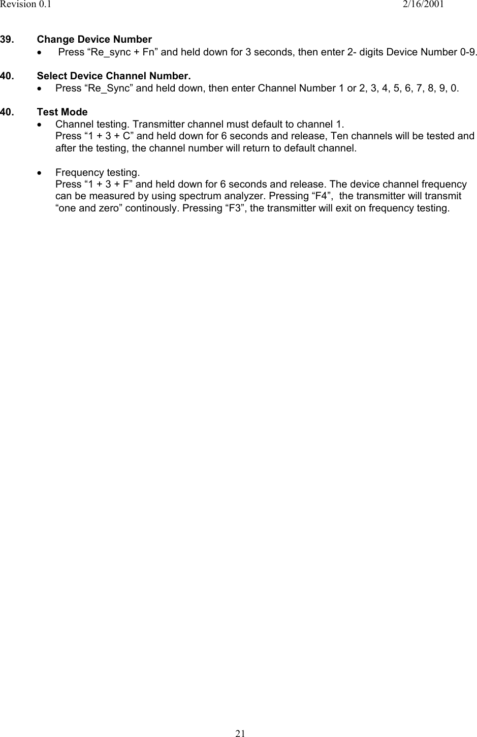
![Revision 0.1 2/16/2001 19 Table 12: Scan Code Table Key # Description Make Code Break Code Key # Description Make Code Break Code 1 ESC 01 81 61 Page Down 3D BD 2 F1 02 82 62 L_Shift 3E BE 3 F2 03 83 63 Z 3F BF 4 F3 04 84 64 X 40 C0 5 F4 05 85 65 C 41 C1 6 F5 06 86 66 V 42 C2 7 F6 07 87 67 B 43 C3 8 F7 08 88 68 N 44 C4 9 F8 09 89 69 M 45 C5 10 F9 0A 8A 70 , / < 46 C6 11 F10 0B 8B 71 . / > 47 C7 12 F11 0C 8C 72 / / ? 48 C8 13 F12 0D 8D 73 Right_Shift 49 C9 14 Num_Lock 0E 8E 74 Up Arrow 4A CA 15 Print Scrn 0F 8F 75 End 4B CB 16 Scroll Lock 10 90 76 Control 4C CC 17 Pause 11 91 77 FN 4D CD 18 ` / ~ 12 92 78 LWIN 4E CE 19 1 / ! 13 93 79 ALT 4F CF 20 2 / @ 14 94 80 Space Bar 50 D0 21 3 / # 15 95 81 APP 51 D1 22 4 / $ 16 96 82 INS 52 D2 23 5 / % 17 97 83 DEL 53 D3 24 6 / ^ 18 98 84 Left Arrow 54 D4 25 7 / & 19 99 85 Down Arrow 55 D5 26 8 / * 1A 9A 86 Right Arrow 56 D6 27 9 / ( 1B 9B 87 Reverse 57 D7 28 0 / ) 1C 9C 88 Play 58 D8 29 - / _ 1D 9D 89 Forward 59 D9 30 = / + 1E 9E 90 Record 5A DA 31 Back Space 1F 9F 91 Stop 5B DB 32 Home 20 A0 92 Pause 5C DC 33 Tab 21 A1 93 Instant Replay 5D DD 34 Q 22 A2 94 Jump CH 5E DE 35 W 23 A3 95 Jump Present 5F DF 36 E 24 A4 96 EPG 60 E0 37 R 25 A5 97 +100 61 E1 38 T 26 A6 98 Multi-View 62 E2 39 Y 27 A7 99 Back 63 E3 40 U 28 A8 100 Forward 64 E4 41 I 29 A9 101 Stop 65 E5 42 O 2A AA 102 Refresh 66 E6 43 P 2B AB 103 Search 67 E7 44 [ / { 2C AC 104 Favorites 68 E8 45 ] / } 2D AD 105 Web home 69 E9 46 \ / | 2E AE 106 Get mail 6A EA 47 Page Up 2F AF 107 Mute 6B EB 48 Caps Lock 30 B0 108 Pip 6C EC 49 A 31 B1 109 Previous 6D ED 50 S 32 B2 110 Menu 6E EE 51 D 33 B3 111 Channel Up 6F EF 52 F 34 B4 112 Channel Down 70 F0 53 G 35 B5 113 Right Click * * 54 H 36 B6 114 Left Click * * 55 J 37 B7 115 Volume Down 73 F3 56 K 38 B8 115 Volume Up 74 F4 57 L 39 B9 115 Power 75 F5 58 ; / : 3A BA 116 Re-Sync 76 F6 59 ' / " 3B BB 117](https://usermanual.wiki/NMB-Technologies/3900/User-Guide-230886-Page-19.png)