NMB Technologies 3900 RF Keyboard with Integrated Pointing Device User Manual NMB TECHNOLOGIES user guide
NMB Technologies Corp. RF Keyboard with Integrated Pointing Device NMB TECHNOLOGIES user guide
users manual
Revision 0.1 2/16/2001
1
NMB TECHNOLOGIES
9730 INDEPENDENCE AVE
CHATSWORTH, CA 91311
U.S.A
TEL: (818) 341-3355
FAX: (818) 772-0866
Requirement Specification
For the
NMB Wireless Keyboard with POINTING Devices
and
RF-Receiver and the HOST(Viewsonic)
Rev. 0.4

Revision 0.1 2/16/2001
2
Revision History
DATE Revision Changes and Additions By
02/16/01 0.1 First Draft Ely Palarca
04/22/01 0.2 Ely Palarca
07/09/01 0.3 Ely Palarca
11/27/01 0.4 Ely Palarca
Revision 0.1 2/16/2001
3
CONTENT
1. INTRODUCTION .....................................................................................................................................................................................................4
2. OVERVIEW ............................................................................................................................................................................................................4
3. UART INTERFACE ...............................................................................................................................................................................................4
4. POWER-ON-RESET ..............................................................................................................................................................................................5
5. SLEEP MODE ........................................................................................................................................................................................................5
6. WAKE UP MODE...................................................................................................................................................................................................5
7. DATA PACKET.......................................................................................................................................................................................................6
8. KEY TYPES ...........................................................................................................................................................................................................7
9. STUCK KEY ...........................................................................................................................................................................................................7
10. KEYBOARD OR REMOTE SLEEP MODE...............................................................................................................................................................7
11. KEEP ALIVE ..........................................................................................................................................................................................................7
12. RESYNC BUTTON .................................................................................................................................................................................................7
13. RF POWER MANAGEMENT ..................................................................................................................................................................................7
14. TRANSMITTER DATA INPUT LEVEL......................................................................................................................................................................7
15. DATA CODING.......................................................................................................................................................................................................7
16. HARDWARE INTERFACE .......................................................................................................................................................................................8
18. GENERAL SPECIFICATION....................................................................................................................................................................................9
19. FREQUENCY PLAN .............................................................................................................................................................................................10
20. FREQUENCY CONTROL......................................................................................................................................................................................10
21. FUNCTIONAL BLOCK DIAGRAM..........................................................................................................................................................................11
22. UART INTERFACE .............................................................................................................................................................................................11
23.
POWER DOWN....................................................................................................................................................................................................12
24. TIMING PROTOCOL.............................................................................................................................................................................................12
25. SET/RESET KEYBOARD STATUS INDICATORS .................................................................................................................................................12
26. REPEAT KEYS.....................................................................................................................................................................................................12
27. DEVICE ID AND DEVICE NUMBER .....................................................................................................................................................................12
28. CHANNEL SYNCHRONIZATION ...........................................................................................................................................................................13
29. COMMANDS SUMMARY ......................................................................................................................................................................................14
30. NMB KEYBOARD DATA PACKET.......................................................................................................................................................................16
31. REMOTE UEI KEY DATA PACKET .....................................................................................................................................................................16
32. NMB POINTING DEVICE DATA PACKET ...........................................................................................................................................................17
33. UEI POINTING DEVICE DATA PACKET..............................................................................................................................................................17
34. STUCK KEY DATA PACKET ................................................................................................................................................................................17
35. SLEEP DATA PACKET.........................................................................................................................................................................................18
36.
KEEP ALIVE DATA PACKET................................................................................................................................................................................18
37. RF-RECEIVER CONNECTOR ..............................................................................................................................................................................18
38. RF-RECEIVER MECHANICAL ..............................................................................................................................................................................18
FIGURES
FIGURE 1: RF- RECEIVER AND IP-BOARD INTERFACE (UART).................................................................................................................................4
FIGURE 2: UART PROTOCOL .......................................................................................................................................................................................4
FIGURE 3.........................................................................................................................................................................................................................7
FIGURE 4: RF- RECEIVER AND IP-BOARD INTERFACE (UART)...............................................................................................................................11
FIGURE 5: UART PROTOCOL .....................................................................................................................................................................................12
TABLES
TABLE 1: DATA FRAME.................................................................................................................................................................................................4
TABLE 2: RF_TRANSMITTER / RF_RECEIVER HARDWARE INTERFACE ...................................................................................................................8
TABLE 3...........................................................................................................................................................................................................................8
TABLE 4: TRANSMITTER FREQUENCY PLAN .............................................................................................................................................................10
TABLE 5: RECEIVER FREQUENCY PLAN....................................................................................................................................................................10
TABLE 6: FREQUENCY CONTROL FOR TRANSMITTER..............................................................................................................................................11
TABLE 7: FREQUENCY CONTROL FOR RECEIVER ....................................................................................................................................................11
TABLE 8: DATA FRAME...............................................................................................................................................................................................12
TABLE 9: DEVICE ID AND REMOTE DEVICES ............................................................................................................................................................12
TABLE 10: RF-RECEIVER COMMANDS FROM THE HOST ..........................................................................................................................................14
TABLE 11: RF-RECEIVER CONNECTOR PINOUT..........................................................................................................................................................18
TABLE 12: SCAN CODE TABLE.....................................................................................................................................................................................19
Revision 0.1 2/16/2001
4
1. Introduction
This document gives the minimum firmware specification required for a Custom Wireless NMB Keyboard
with Pointing Device which is intended to be used with the Viewsonic Display Monitor.
2. Overview
This battery-powered remote keyboard transmits RF signal to the Base Unit (RF-Receiver), which
connects to the Viewsonic Large Screen Monitor display unit through an UART serial interface. The
communication medium is 2.4GHZ. It has 10 programmable channels and each remote unit has its
Device ID to avoid interference.
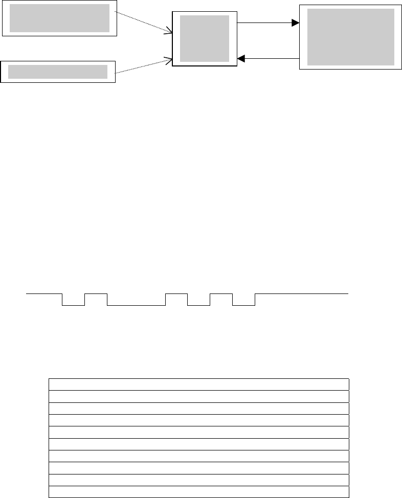
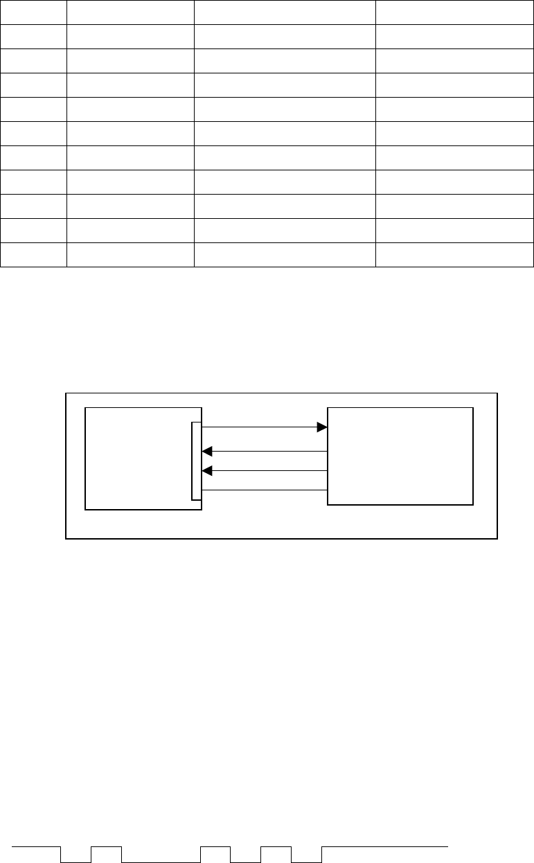
Functional Block Diagram
RF TX TX
(UART)
RX
RF TX
Figure 1: Keyboard/Remote, RF- Receiver and IP-Board interface (UART)
• The NMB remote devices communicate wirelessly through the Base Unit (RF-Receiver) one way
and the Viewsonic Display Monitor interfaces to the Base Unit through an UART port.
• The NMB keyboard and the UEI Remote must have a minimum distance of one meter from the
RF-Receiver for proper operation.
3. UART Interface
The UART interface requires only four lines, Receive (RX), Transmit (TX), GND, and +5Vcc.
The communication link will be half-duplex; meaning that each side is either a RF-Receiver or the HOST
at any given time.
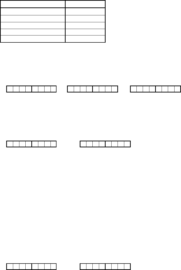
3.1 Protocol Format of RF-RECEIVER (UART) to the HOST.
The RF-Receiver communicates serially with the Host at 9600-baud over a 4-lines connection.
Data packets are exchanged over the Receive and Transmit line.
Start 0 1 2 3 4 5 6 7 Stop
Idle (51 hex) Idle
Figure 2: UART Protocol
3.2 Data Frame
Bit 1 Start Bit Always '0'
Bit 2 D0 Data 0 (LSB)
Bit 3 D1 Data 1
Bit 4 D2 Data 2
Bit 5 D3 Data 3
Bit 6 D4 Data 4
Bit 7 D5 Data 5
Bit 8 D6 Data 6
Bit 9 D7 Data 7 (MSB)
Bit 10 Stop Bit Always '1'
Table 1:Data Frame
NMB Keyboard
with Pointing Base Unit
Receiver
Viewsonic
Large Screen
Display Monitor
UEI Remote Control
Revision 0.1 2/16/2001
5
4. Power-On-Reset
The wireless Keyboard with Pointing Device will generates a "power-on-reset" when power is first applied
to the unit. The keyboard will test the checksum of the read-only memory (ROM), and random access
memory (RAM) test. On satisfactory completion of the test, keyboard scanning begins and the pointing
device will begin scan the sensor.
5. Sleep Mode
The keyboard and the pointing device unit are to provide reduced power consumption sleep mode. If no
data packet is transmitted within XX seconds, RF transmitter can go to sleep mode. While in this mode,
the unit must maintain the current status.
6. Wake Up Mode
When the keyboard key or pointing device is pressed or moved, the unit will wake up and transmit the key
data or movement data.

Revision 0.1 2/16/2001
6
7. Data Packet
It is recommended that for the FSK direct modulation system of the RF communications, the Data Format
below is recommended.
Sync Byte Preamble Device
Number
Device ID/
Status
X Coord
/
Y Coord /
Scan code
Checksum
16 bits 16 bits 8bits 8 bits 8 bits 8 bits 8 bits
Baud: 9600-baud rate (104.1 us/bit)
Total bits: 64 bits
Sync Bytes: Sync data bytes are used to stabilize the demodulation of the receiver side after a period
of no signal input. Recommended four byte of "hex 0F".
Preamble: It is used for decoder bit sync. Recommended 2 bytes of "hex 55".
Device Number: 8-bits, Device number will be maximum of decimal 99, hex 63
Device ID/ Status: 8-bits
Device ID:
Bit 0 - Bit 2 = 000b for RF-Receiver, 001b for NMB keyboard,
010b for UEI key data, 011b for NMB Pointing device, 100b for UEI Pointing
device
Keyboard Status Data:
Bit 3 = Reserved (0)
Bit 4 = Reserved (0)
Bit 5 = Reserved (0)
Bit 6 = Reserved (0)
Bit 7 = Battery Status (0=ok, 1= low)
Pointing Device Status Data:
Bit 3 = Pointing Device Left Button Status (1 = Down, 0 = Up)
Bit 4 = Pointing Device Right Button Status (1 = Down, 0 = Up)
Bit 5 = X coordinate sign (0 = positive, 1 = negative)
Bit 6 = Y coordinate sign (0 = positive, 1 = negative)
Bit 7 = Battery Status (0=ok, 1= low)
X coordinate/ : 8 bits
Keyboard Data = Reserved (0)
Pointing Device =X-Data: 8 bits
Y coordinate/ Scan code: 8 bits
Keyboard Data: Scan Code (Make/Break) * Scan codes are shown in Table 2
Pointing Device = Y-Data: 8 bits
Checksum: (Device Number + Device ID/ Status + Xcoord + Ycoord/Scan Code)
Revision 0.1 2/16/2001
7
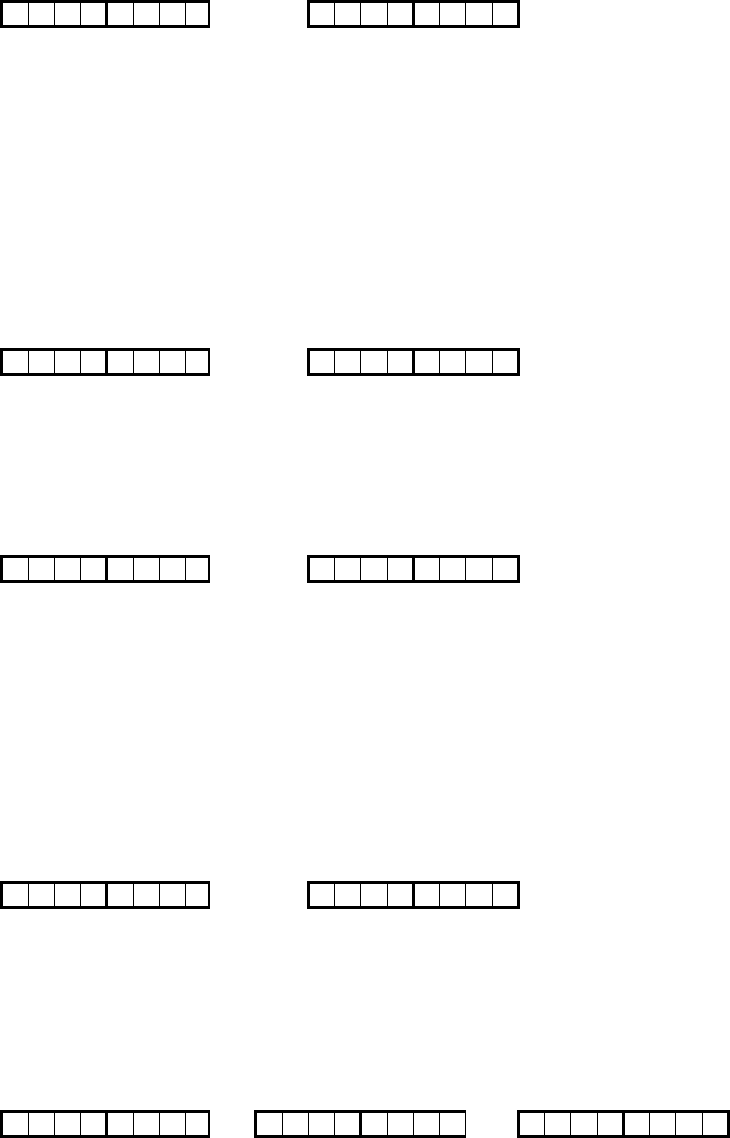
8. Key Types
All keys including the Pointing Device buttons are make/break. When a key or button is pressed, the unit
will transmit the following data as shown in the protocol.
For reliable data transmission, keystroke and control push buttons packets are transmitted twice
wirelessly from NMB Remote Devices.
MAKE 8ms MAKE BREAK 8ms BREAK
9. Stuck key
Transmitter shall enable the "Stuck Key" bit and transmit it to the Receiver when a stuck key is detected
after xx ms.
10. Keyboard or Remote Sleep Mode
The remote devices shall enable the "Sleep Mode" bit when the Remote or Keyboard is to enter Sleep
Mode.
11. Keep Alive
The remote devices shall enable the "Keep Alive" bit when the user is holding a key down (not typing) for
more than 70ms.
12. Resync Button
Hold down the Resync button and press one of the numeric keys (1-0) to select the channel number. At
this time, the 'signature ID' (Resync make code = 76hex) will be sent at the selected channel. The data
format of the signature ID is the same as the key data packet described in the NMB keyboard data packet.
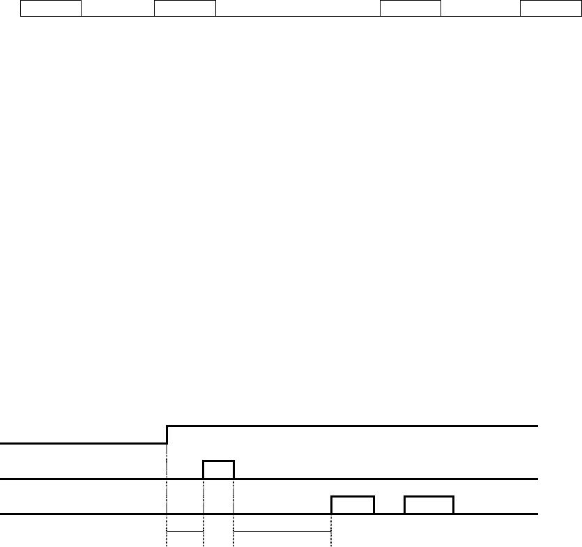
13. RF Power Management
RF Power On
Allocate Frequency X
Tx Data Input X X
T1 T2
Figure 3. Timing Sequence in RF Power Management.
• T1 = Power On Stable Time. Typically, it should be T1 > 5ms
• T2 = Frequency Stable Time. Typically, it should be T2 > 20ms
14. Transmitter Data Input Level
The transmitter data input level should be fixed as the supply voltage drops when using battery. It is
required that the Input level will be Vp-p = 100mv (+/- 10%).
15. Data Coding
Data coding is necessary for the wireless communication, which is to eliminate the DC offset of the
demodulation caused by the series of 1's or 0's. The Manchester Coding is recommended here.
Revision 0.1 2/16/2001
8
16. Hardware Interface
The interface to the RF-Transmitter and RF-Receiver module shall be described in the table below.
Parameter Pin Number Tx-Module Rx-Module
Input voltage 1 2.2 V min. 3.3 V min.
Ground 2 Ground Ground
TX-Data Input 3 Data input Data output
Synthesizer Enable 4 TTL input TTL input
Synthesizer SDA 5 TTL input TTL input
Synthesizer SCK 6 TTL input TTL input
Table 2:RF_Transmitter / RF_Receiver Hardware Interface
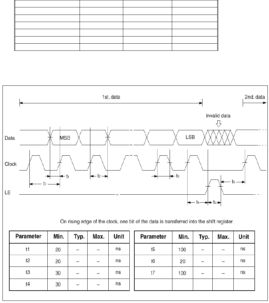
17. Serial Input Data Timing
Table 3. Serial Input Data Timing for Selecting Channel.
Revision 0.1 2/16/2001
9
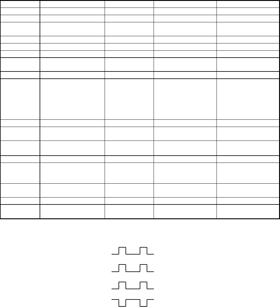
18. General Specification
The performance requirements are contained in the table below
Table 2. General Specification
Rqmt No. Parameter Description Tx Module Rx Module
4.1 Number of channels 10 channels 10 channels*
4.2 Channel spacing 500 kHz N/A
4.3 Receive frequency
band
N/A 2400 to 2483.5 MHz
4.4 Demodulation N/A FSK detection
4.5 Receiver sensitivity Minimum N/A -90 dBm
4.6 Data rate Maximum 19.2 kbps 19.2 kbps
4.7 Transmit frequency
band
2400 to 2483.5 MHz N/A
4.8 Modulation FSK N/A
4.9 Radiated power
FCC Requirements
Maximum
Fundamental
Spurious
emissions
-10 dBm
50 millivolts/meter @
3 meters
500 microvolts/meter
@ 3 meters
N/A
N/A
500 microvolts/meter
@ 3 meters
4.10 Duplex type Transmit only Receive only
4.11 RF frequency
tolerance
± 10 ppm ± 10 ppm
4.12 Temperature range Operating
Storage
0 to 50 °C
-10 to 60 °C
0 to 50 °C
-10 to 60 °C
4.13 Power source Nominal 2.5 VDC 3.3 VDC
4.14 Power consumption Maximum
operational
supply current
15 mA 40 mA
4.15 Dimensions 28mm x 22mm x
8mm
32 mm x 45mm x
8mm
4.16 Weight To be determined To be determined
4.17 Other requirements PLL lock on
time
50 ms 10 ms
Note
* : The output data of channel 1-5 and channel 6-10 are different.
Channel 1~5 : Tx input
data
Rx output
data

Revision 0.1 2/16/2001
10
19. Frequency Plan
Table 4: Transmitter Frequency Plan
Channel Tx module transmit
frequency
1 2446.7 MHz
2 2448.7 MHz
3 2449.7 MHz
4 2451.7 MHz
5 2454.7 MHz
6 2456.3 MHz
7 2457.3 MHz
8 2459.3 MHz
9 2462.3 MHz
10 2464.3 MHz
Table 5: Receiver Frequency Plan
Channel Rx module Local
frequency
1 2436.0 MHz
2 2438.0 MHz
3 2439.0 MHz
4 2441.0 MHz
5 2444.0 MHz
6 2467.0 MHz
7 2468.0 MHz
8 2470.0 MHz
9 2473.0 MHz
10 2475.0 MHz
20. Frequency Control
Serial data is processed using SDA, SCK, LE pins of the RF-Module for the Transmitter and the Receiver.
Binary serial data is entered through the SDA pin. One bit of data is shifted into the shift register onto the
rising edge of the clock (SCK). When the load enable (LE) pin is high, stored the data latched. After the
two 19-bit register being latched, the frequency will be locked.
CH Freq. 19-bit Register 19-bit Register
1 2446.7 MHz 0010000000001010001 0010111111000100110
2 2448.7 MHz 0010000000001010001 0010111111001001110
3 2449.7 MHz 0010000000001010001 0010111111001100010
4 2451.7 MHz 0010000000001010001 0010111111010001010
5 2454.7 MHz 0010000000001010001 0010111111011000110
6 2456.3 MHz 0010000000001010001 0010111111101100110
7 2457.3 MHz 0010000000001010001 0010111111101111010
8 2459.3 MHz 0010000000001010001 0010111111110100010
9 2462.3 MHz 0010000000001010001 0010111111111011110
10 2464.3 MHz 0010000000001010001 0011000000010000110
Revision 0.1 2/16/2001
11
Table 6:Frequency Control for Transmitter
CH Freq. 19-bit Register 19-bit Register
1 2436.0 MHz 1011000000000010001 0000100101101001000
2 2438.0 MHz 1011000000000010001 0000100101101001100
3 2439.0 MHz 1011000000000010001 0000100101101001110
4 2441.0 MHz 1011000000000010001 0000100101101010010
5 2444.0 MHz 1011000000000010001 0000100101101011000
6 2467.0 MHz 1011000000000010001 0000100101110000110
7 2468.0 MHz 1011000000000010001 0000100101110001000
8 2470.0 MHz 1011000000000010001 0000100101110001100
9 2473.0 MHz 1011000000000010001 0000100101110010010
10 2475.0 MHz 1011000000000010001 0000100110001010110
Table 7: Frequency Control for Receiver
* Default Remote Device Channel will be number 1 and Device Number will 00 respectively.
21. Functional Block Diagram
Figure 4: RF- Receiver and IP-Board interface (UART)
22. UART Interface
The UART interface requires only four lines, Receive (RX), Transmit (TX), GND, and +5Vcc.
The communication link will be half-duplex; meaning that each side is either a RF-Receiver or the HOST
at any given time.
22.1 Protocol Format of RF-RECEIVER (UART) to the HOST.
The RF-Receiver communicates serially with the Host at 9600-baud over a 4-lines connection.
Data packets are exchanged over the Receive and Transmit line.
The RF-Receiver only sends one make and one break code for each key pressed. After 70ms,
Keep alive packet will be send until the key press is released.
Start 0 1 2 3 4 5 6 7 Stop
Idle (51 hex) Idle
RF- RECEIVER
UNIT
Tx
RxD
+5V
GND
IP-Board

Revision 0.1 2/16/2001
12
Figure 5: UART Protocol
22.2 Data Frame
Bit 1 Start Bit Always '0'
Bit 2 D0 Data 0 (LSB)
Bit 3 D1 Data 1
Bit 4 D2 Data 2
Bit 5 D3 Data 3
Bit 6 D4 Data 4
Bit 7 D5 Data 5
Bit 8 D6 Data 6
Bit 9 D7 Data 7 (MSB)
Bit 10 Stop Bit Always '1'
Table 8: Data Frame
23. Power Down
In the event of Power Down, all the critical parameters and Channel Number in the RF-Transmitter and
RF-Receiver unit will be save.
24. Timing Protocol
Transmission of Data Packet between the RF-Receiver and the HOST must have a delay at least four
byte times (about 4ms at 9600 baud) between the last byte of one data packet and the first byte of the ID
code of the next data packet.
There must be no more than two bytes times delay (about 2ms at 9600 baud) between the ID code and
data byte(s) within a packet.
25. Set/Reset Keyboard Status Indicators
Three Status indicators Num Lock, Caps Lock, and Scroll Lock can be activated or deactivated by
pressing the respective keys from the transmitter keyboard. Once the HOST receives the scan code of
these keys, the HOST will activate and deactivate the status of each function in the screen
26. Repeat Keys
When a key is pressed and held, the make scan code is sent. After a delay of 70ms +/- 20%, the Remote
Device will send a "Keep Alive Data"- packet every 70ms until the break scan code is received.
27. Device ID and Device Number
When remote device has a Device ID and Device Number. Device ID shows the category of the Remote
device. The following table shows the device Ids for different categories.
Remote Device Device ID
Keyboard Keypad 1
Remote Control Keypad 2
Keyboard Pointing Device 3
Remote Control Pointing Device 4
Table 9: Device ID and Remote Devices
Revision 0.1 2/16/2001
13
Device Number is pre-loaded in the factory before the device is shipped. The number is chosen randomly
from 0 to 99. The Host will validate the received data packet by checking the Device Number is
registered for that Device ID or not. After the channel synchronization, the Device Number of each
remote device will be registered in the host. Note that for both keyboard and remote control, keypad and
pointing device have the same Device Number. During synchronization, only Device ID of the keypad
and the Device Number will be sent. The host should also register the Device Number for the pointing
device of the corresponding device.
28. Channel Synchronization
There are 10 channels, which are numbered from 1 to 0, to be used in the communication between the
RF-Receiver and the remote devices as keyboard and remote control.
For reliable data transmission, keystroke and control push buttons packets are transmitted twice
wirelessly from UEI /NMB Devices.
28.1 Changing Channel of the RF-Receiver
The Host using the command “Set Channel” can change the channel of the RF-Receiver. The
details can be found in the section, Set Channel. Normally, the HOST will show the channel
number on the screen and then wait for the reception of the signatures (i.e. Re-Sync code, 76hex,
defined in Table 2) from the remote devices for confirmations.
28.2 Changing Channel of the Remote Device
The channel of the remote device can be changed as the following procedure.
1. Hold down the Sync button on the device
2. Press the button on the numeric keypad on the remote device to select the channel
number. At this time, the signature will be sent continuously at the selected channel until
the button is released. The data format of the signature id the same as the key data
packet describe in the section, NMB keyboard Data Packet.
Revision 0.1 2/16/2001
14
29. Commands Summary
The following commands that the HOST may send and their hexadecimal values.
Table 10: RF-Receiver commands from the HOST
Command Hex Value
Set Channel F1
Channel Open F2
Channel Close F3
Get Version Number F4
Read RSSI F5
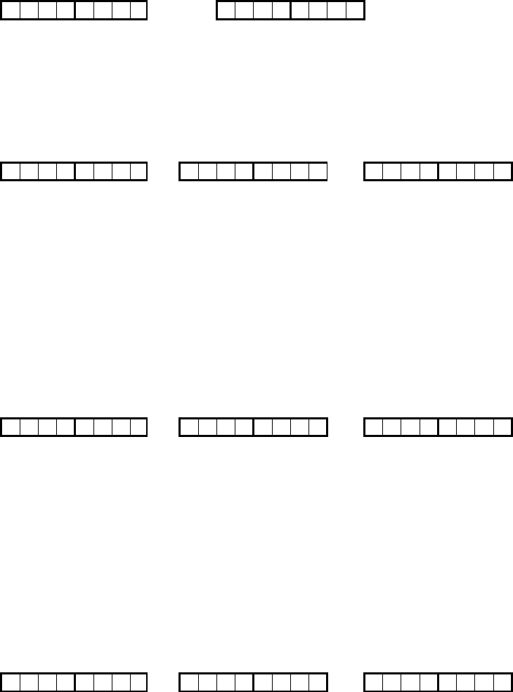
29.1 Set Channel (Hex F1)
This command will be used to set the RF channel of the receiver.
Host Command:
< Channel Number > <hex F1> < Device ID=0 >
7 6 5 4 3 2 1 0 1 1 1 1 0 0 0 1 0 0 0 0 0 0 0 0
3rd Byte 2nd Byte 1st Byte
1st Byte: Bit 0 - Bit 2 = < Device ID = 000b >
Bit 3 - Bit 7 = Reserved
2nd Byte: <CMD =hex F1>
3rd Byte: <Channel Number>
RF-Receiver Respond:
7 6 5 4 3 2 1 0 0 0 0 0 0 0 0 0
2nd Byte 1st Byte
1st Byte Bit 0 - Bit 2 = < Device ID = 000b >
Bit 3 - Bit 7 = Reserved
2nd Byte <Channel Number>
29.2 Channel Open / Close Commands
The System can issue Channel Open or Close commands ( hex F2 or hex F3) to the RF-Receiver.
The default state on power-on will be Channel Close. When the Channel is Close the RF-
Receiver will ignore incoming RF data.
29.2.1 Channel Open ( Hex F2)
On the receipt of this command, The RF-Receiver will open the communication link
between the HOST and RF-Receiver.
Host Command:
<hex F2> < Device ID=0 >
1 1 1 1 0 0 1 0 0 0 0 0 0 0 0 0
2nd Byte 1st Byte
1st Byte: Bit 0 - Bit 2 = < Device ID=0 >
Bit 3 - Bit 7 = Reserved
Revision 0.1 2/16/2001
15
2nd Byte: <CMD =hex F2>
RF-Receiver Respond:
7 6 5 4 3 2 1 0 0 0 0 0 0 0 0 0
2nd Byte 1st Byte
1st Byte Bit 0 - Bit 2 = < Device ID = 000b >
Bit 3 - Bit 7 = Reserved
2nd Byte <Channel Number>
29.2.2 Channel Closed ( Hex F3)
On the receipt of this command, The RF-Receiver will closed the communication link between the
HOST and RF-Receiver.
Host Command:
<hex F3> < Device ID=0 >
1 1 1 1 0 0 1 1 0 0 0 0 0 0 0 0
2nd Byte 1st Byte
1st Byte: Bit 0 - Bit 2 = < Device ID=0 >
Bit 3 - Bit 7 = Reserved
2nd Byte: <CMD =hex F3>
RF-Receiver Respond:
7 6 5 4 3 2 1 0 0 0 0 0 0 0 0 0
2nd Byte 1st Byte
1st Byte Bit 0 - Bit 2 = < Device ID = 000b >
Bit 3 - Bit 7 = Reserved
2nd Byte <Channel Number >
29.3 Get Version Number ( Hex F4)
On the receipt of this command, The RF-Receiver will send the version number of the firmware to
the HOST.
Host Command:
<hex F4> < Device ID=0 >
1 1 1 1 0 0 1 1 0 0 0 0 0 0 0 0
2nd Byte 1st Byte
1st Byte: Bit 0 - Bit 2 = < Device ID=0 >
Bit 3 - Bit 7 = Reserved
2nd Byte: <CMD =hex F4>
RF-Receiver Respond:
< Channel Number > <Device ID> < Version Number >
7 6 5 4 3 2 1 0 0 0 0 0 0 0 0 0 0 0 0 0 0 0 0 0
3rd Byte 2nd Byte 1st Byte
1st Byte <Version Number, max = dec. 99, hex 63>
2nd Byte Bit 0 - Bit 2 = < Device ID = 000b >
Bit 3 - Bit 7 = Reserved
Revision 0.1 2/16/2001
16
3rd Byte <Channel Number >
29.4 Read RSSI ( Hex F5) Not implemented
On the receipt of this command, The RF-Receiver will send the RSSI value of the current channel
to the HOST. This command is used for testing purpose or future enhancement.
Host Command:
<hex F5> < Device ID=0 >
1 1 1 1 0 0 1 1 0 0 0 0 0 0 0 0
2nd Byte 1st Byte
1st Byte: Bit 0 - Bit 2 = < Device ID=0 >
Bit 3 - Bit 7 = Reserved
2nd Byte: <CMD =hex F5>
RF-Receiver Respond:
< Channel Number > <Device ID> < RSSI value,max=dec.255 >
7 6 5 4 3 2 1 0 0 0 0 0 0 0 0 0 0 0 0 0 0 0 0 0
3rd Byte 2nd Byte 1st Byte
1st Byte < RSSI value,max=dec.255 >
2nd Byte Bit 0 - Bit 2 = < Device ID = 000b >
Bit 3 - Bit 7 = Reserved
3rd Byte <Channel Number >
30. NMB Keyboard Data Packet
The Keyboard data packet format is three bytes long. The first byte consists of the Device Number
followed by the second byte = Device ID (001b) and the battery status bit, the third byte = Scan Code
(Make/Break) of the Keyboard. Scan Code Table 10
<Scan Code> Device ID + Battery Status <Device Number>
7 6 5 4 3 2 1 0 7 0 0 0 0 0 0 1 7 6 5 4 3 2 1 0
3rd Byte 2nd Byte 1st Byte
1st Byte: <Device number, max. of dec. 99>
2nd Byte: Bit 0 - Bit 2 = Device ID = 001b
Bit 3 - Bit 6 = Reserved ( 0 )
Bit 7 = Battery Status, 0 = ok, 1 = low
3rd Byte: <Scan Code> (Make / Break) * Scan Code are shown
31. Remote UEI Key Data Packet
The Remote UEI key data packet format is three bytes long. The first byte consists of the Device Number
followed by the second byte = Device ID (010b) and the battery status bit, the third byte = Scan Code
(Make/Break) of the Remote Key. Scan Code Table 10.
<Scan Code> Device ID + Battery Status <Device Number>
7 6 5 4 3 2 1 0 7 0 0 0 0 0 1 0 7 6 5 4 3 2 1 0
3rd Byte 2nd Byte 1st Byte
1st Byte: <Device number, max. of dec. 99, hex 63>
2nd Byte: Bit 0 - Bit 2 = Device ID = 010b
Bit 3 - Bit 6 = Reserved ( 0 )
Bit 7 = Battery Status, 0 = ok, 1 = low
3rd Byte: <Scan Code> (Make / Break) * Scan Code are shown
Revision 0.1 2/16/2001
17
32. NMB Pointing Device Data Packet
The data packet format is four bytes long.
7 6 5 4 3 2 1 0 7 6 5 4 3 2 1 0 7 6 5 4 3 0 1 1 7 6 5 4 3 2 1 0
4th 3rd Byte 2nd Byte 1st Byte
1st Byte: <Device Number, max = dec 99, hex 63>
2nd Byte: Bit 0 - Bit 2 = Device ID = 011b
Bit 3 = Left Button Status (1=Down, 0=Up
Bit 4 = Right Button Status (1=Down, 0=Up)
Bit 5 = X-Coordinate sign (0=positive, 1=negative)
Bit 6 = Y-Coordinate Sign (0=positive, 1=negative)
Bit 7 = Battery Status, 0 = ok, 1 = low)
3rd Byte: <X-data>
4th Byte: <Y- data>
33. UEI Pointing Device Data Packet
The data packet format is four bytes long.
7 6 5 4 3 2 1 0 7 6 5 4 3 2 1 0 7 6 5 4 3 1 0 0 7 6 5 4 3 2 1 0
4th 3rd Byte 2nd Byte 1st Byte
1st Byte: <Device Number, max = dec 99, hex 63>
2nd Byte: Bit 0 - Bit 2 = Device ID = 100b
Bit 3 = Left Button Status (1=Down, 0=Up
Bit 4 = Right Button Status (1=Down, 0=Up)
Bit 5 = X-Coordinate sign (0=positive, 1=negative)
Bit 6 = Y-Coordinate Sign (0=positive, 1=negative)
Bit 7 = Battery Status, 0 = ok, 1 = low)
3rd Byte: <X-data>
4th Byte: <Y- data>
34. Stuck Key Data Packet
Receiver shall send this command when a stuck key is detected.
<hex FC> Device ID + Battery Status <Device Number>
7 6 5 4 3 2 1 0 7 0 0 0 0 2 1 0 7 6 5 4 3 2 1 0
3rd Byte 2nd Byte 1st Byte
1st Byte: <Device number, max. of dec. 99, hex 63>
2nd Byte: Bit 0 - Bit 2 = Device ID (001 = Keyboard, 010b = Remote)
Bit 3 - Bit 6 = Reserved ( 0 )
Bit 7 = Battery Status, 0 = ok, 1 = low
3rd Byte: <CMD = hex FC>
Revision 0.1 2/16/2001
18
35. Sleep Data Packet
Receiver shall send this command when the Remote or the wireless keyboard is about to enter sleep
mode. This way, the IP board can fully aware of the transmitter state.
<hex FD> Device ID + Battery Status <Device Number>
7 6 5 4 3 2 1 0 7 0 0 0 0 2 1 0 7 6 5 4 3 2 1 0
3rd Byte 2nd Byte 1st Byte
1st Byte: <Device number, max. of dec. 99, hex 63>
2nd Byte: Bit 0 - Bit 2 = Device ID = 010b
Bit 3 - Bit 6 = Reserved ( 0 )
Bit 7 = Battery Status, 0 = ok, 1 = low
3rd Byte: <CMD = hex FD
36. Keep Alive Data Packet (Revised)
This code will be sent only when the user is holding a key down (not typing), this is to provide a keep alive
timeout in the IP board. If the Keep Alive code is not receive within 200ms, the IP board will timeout and
release the Break Code of the held key.
<hex FE> Device ID + Battery Status <Device Number>
7 6 5 4 3 2 1 0 7 0 0 0 0 0 1 0 7 6 5 4 3 2 1 0
3rd Byte 2nd Byte 1st Byte
1st Byte: <Device number, max. of dec. 99, hex 63>
2nd Byte: Bit 0 - Bit 2 = Device ID (0 01 = keyboard, 010= remote control)
Bit 3 - Bit 6 = Reserved ( 0 )
Bit 7 = Battery Status, 0 = ok, 1 = low
3rd Byte: <CMD =hex FE>
37. RF-Receiver connector
Connector type:
Vendor: Long Chu Electronics Co. Ltd
Type: P200 (Straight Type)
Pitch: 2.0mm
Current rating: 2amp
Insulation Resistance: 1000 mega ohm, min.
Table 11: RF-Receiver connector pinout
Pin # Name Comments
1 Vcc +5V power
2 GND Ground
3 RxD Received serial data from IP board to RF-Receiver.
4 TxD Transmitted serial data from RF-Receiver to IP board.
5 NC No Connect
6 GND Ground
38. RF-Receiver mechanical
Add mechanical outline of module including dimension, mounting, etc..

Revision 0.1 2/16/2001
19
Table 12: Scan Code Table
Key # Description Make Code Break Code Key # Description Make Code Break Code
1 ESC 01 81 61 Page Down 3D BD
2 F1 02 82 62 L_Shift 3E BE
3 F2 03 83 63 Z 3F BF
4 F3 04 84 64 X 40 C0
5 F4 05 85 65 C 41 C1
6 F5 06 86 66 V 42 C2
7 F6 07 87 67 B 43 C3
8 F7 08 88 68 N 44 C4
9 F8 09 89 69 M 45 C5
10 F9 0A 8A 70 , / < 46 C6
11 F10 0B 8B 71 . / > 47 C7
12 F11 0C 8C 72 / / ? 48 C8
13 F12 0D 8D 73 Right_Shift 49 C9
14 Num_Lock 0E 8E 74 Up Arrow 4A CA
15 Print Scrn 0F 8F 75 End 4B CB
16 Scroll Lock 10 90 76 Control 4C CC
17 Pause 11 91 77 FN 4D CD
18 ` / ~ 12 92 78 LWIN 4E CE
19 1 / ! 13 93 79 ALT 4F CF
20 2 / @ 14 94 80 Space Bar 50 D0
21 3 / # 15 95 81 APP 51 D1
22 4 / $ 16 96 82 INS 52 D2
23 5 / % 17 97 83 DEL 53 D3
24 6 / ^ 18 98 84 Left Arrow 54 D4
25 7 / & 19 99 85 Down Arrow 55 D5
26 8 / * 1A 9A 86 Right Arrow 56 D6
27 9 / ( 1B 9B 87 Reverse 57 D7
28 0 / ) 1C 9C 88 Play 58 D8
29 - / _ 1D 9D 89 Forward 59 D9
30 = / + 1E 9E 90 Record 5A DA
31 Back Space 1F 9F 91 Stop 5B DB
32 Home 20 A0 92 Pause 5C DC
33 Tab 21 A1 93 Instant Replay 5D DD
34 Q 22 A2 94 Jump CH 5E DE
35 W 23 A3 95 Jump Present 5F DF
36 E 24 A4 96 EPG 60 E0
37 R 25 A5 97 +100 61 E1
38 T 26 A6 98 Multi-View 62 E2
39 Y 27 A7 99 Back 63 E3
40 U 28 A8 100 Forward 64 E4
41 I 29 A9 101 Stop 65 E5
42 O 2A AA 102 Refresh 66 E6
43 P 2B AB 103 Search 67 E7
44 [ / { 2C AC 104 Favorites 68 E8
45 ] / } 2D AD 105 Web home 69 E9
46 \ / | 2E AE 106 Get mail 6A EA
47 Page Up 2F AF 107 Mute 6B EB
48 Caps Lock 30 B0 108 Pip 6C EC
49 A 31 B1 109 Previous 6D ED
50 S 32 B2 110 Menu 6E EE
51 D 33 B3 111 Channel Up 6F EF
52 F 34 B4 112 Channel Down 70 F0
53 G 35 B5 113 Right Click * *
54 H 36 B6 114 Left Click * *
55 J 37 B7 115 Volume Down 73 F3
56 K 38 B8 115 Volume Up 74 F4
57 L 39 B9 115 Power 75 F5
58 ; / : 3A BA 116 Re-Sync 76 F6
59 ' / " 3B BB 117

Revision 0.1 2/16/2001
20
60 Enter 3C BC 118
* Set and Reset in Pointing Device Data Packet.
Revision 0.1 2/16/2001
21
39. Change Device Number
• Press “Re_sync + Fn” and held down for 3 seconds, then enter 2- digits Device Number 0-9.
40. Select Device Channel Number.
• Press “Re_Sync” and held down, then enter Channel Number 1 or 2, 3, 4, 5, 6, 7, 8, 9, 0.
40. Test Mode
• Channel testing. Transmitter channel must default to channel 1.
Press “1 + 3 + C” and held down for 6 seconds and release, Ten channels will be tested and
after the testing, the channel number will return to default channel.
• Frequency testing.
Press “1 + 3 + F” and held down for 6 seconds and release. The device channel frequency
can be measured by using spectrum analyzer. Pressing “F4”, the transmitter will transmit
“one and zero” continously. Pressing “F3”, the transmitter will exit on frequency testing.
FEDERAL COMMUNICATIONS COMMISSION
INTERFERENCE STATEMENT
This equipment has been tested and found to comply with the limits for a Class B
digital device, pursuant to Part 15 of the FCC Rules. These limits are designed
to provide reasonable protection against harmful interference in a residential
installation. This equipment generates, uses and can radiate radio frequency
energy and, if not installed and used in accordance with the instructions, may
cause harmful interference to radio communications. However, there is no
guarantee that interference will not occur in a particular installation. If this
equipment does cause harmful interference to radio or television reception,
which can be determined by turning the equipment off and on, the user is
encouraged to try to correct the interference by one or more of the following
measures:
-- Reorient or relocate the receiving antenna.
-- Increase the separation between the equipment and receiver.
-- Connect the equipment into an outlet on a circuit different from that to which
the receiver is connected.
-- Consult the dealer or an experienced radio/TV technician for help.
CAUTION:
Any changes or modifications not expressly approved by the grantee of this
device could void
the user's authority to operate the equipment.
FCC RF Radiation Exposure Statement
This equipment complies with FCC RF radiation exposure limits set forth for an
uncontrolled environment. This equipment should be installed and operated with
a minimum distance of 20cm between the radiator and your body.