NORDYNE Furnace/Heater, Gas Manual L0523341
M3RL Series L0523341
User Manual: NORDYNE NORDYNE Furnace/Heater, Gas Manual NORDYNE Furnace/Heater, Gas Owner's Manual, NORDYNE Furnace/Heater, Gas installation guides
Open the PDF directly: View PDF ![]() .
.
Page Count: 36
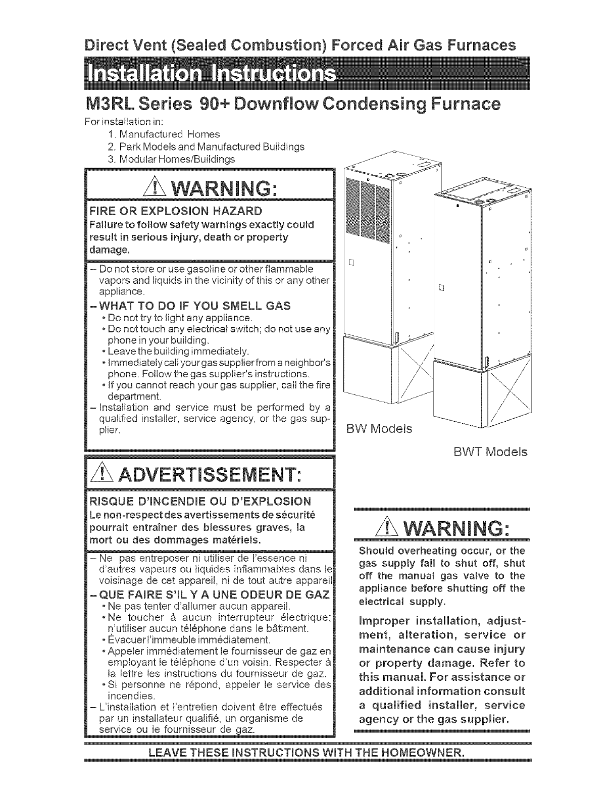
Direct Vent (SeaHed Combustion) Forced Air Gas Furnaces
M3RL Series 90+ Downfiow Condensing Furnace
For installation in:
I. Manufactured Homes
2. Park Models and Manufactured Buildings
3. Modular Homes/Buildings
WARNING:
FiRE OR EXPLOSION HAZARD
Failure to fol!ow safety warnings e×actly could
result in serious injury, death or property
damage.
- Do not store or use gasoline or other flammable
vapors and liquids in the vicinity of this or any other
appliance.
-WHAT TO DO mFYOU SMELL GAS
oDo not try to light any appliance.
oDo not touch any electrical switch; do not use any
phone in your building.
, Leave the building immediately.
oImmediately call your gas supplier from a neighbor s
phone. Follow the gas supplier's instructions.
, If you cannot reach your gas supplier, call the fire
department.
-installation and service must be performed by a
qualified installer, service agency, or the gas sup-
plier.
RISQUE D'INCENDmE OU D'EXPLOSmON
Le non-respect des avertissements de s_curit_
pourrait entra_ner des blessutes graves, la
mort ou des dommages mat_rieJs.
- Ne pas entreposer ni utiliser de I'essence ni
d'autres vapeurs ou liquides inflammables dans Ic
voisinage de cet appareil, ni de tout autre apparei
-QUE FAmRE S'IL YA UNE ODEUR DE GAZ
oNe pas tenter d'allumer aucun appareil.
,Ne toucher a aucun interrupteur 61ectdque;
n'utiliser aucun t616phone dans le b_timent.
oE_vacuerI'immeuble immCdiatement.
, Appeler immCdiatement le foumisseur de gaz en
employant le t616phone d'un voisin. Respecter
la lettre les instructions du foumisseur de gaz.
oSi personne ne repond, appeler le service des
incendies.
- Uinstallation et I'entretien doivent Ctre effectues
par un installateur qualifie, un organisme de
service ou le fournisseur de gaz.
BW Models
BWT Models
WARNING:
Shoumd overheating occur, or the
gas suppty fail to shut off, shut
off the manual gas valve to the
appliance before shutting off the
electrical supply.
Improper installation, adjust-
ment, amteration, service or
maintenance can cause injury
or property damage. Refer to
this manual. For assistance or
additional information consult
a qualified installer, service
agency or the gas supplier.
LEAVE THESE mNSTRUCTmONS WroTHTHE HOMEOWNER.

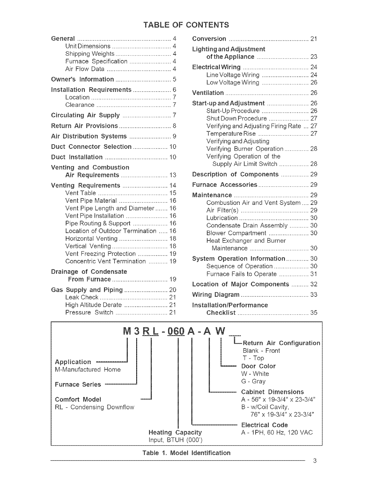
TABLE OF CONTENTS
Generam ...................................................... 4
Unit Dimensions .................................. 4
Shipping Weights ................................ 4
Furnace Specification ........................ 4
Air Flow Data ..................................... 4
Owner's hformation ................................ 5
Installation Requirements ...................... 6
Location .............................................. 7
Clearance ........................................... 7
Circumating Air Supply ............................ 7
Return Air Provisions .............................. 8
Air Distribution Systems ........................ 9
Duct Connector Selection .................... 10
Duct Installation .................................... 10
Venting and Combustion
Air Requirements ........................... 13
Venting Requirements .......................... 14
Vent Table ........................................ 15
Vent Pipe Material ............................ 16
Vent Pipe Length and Diameter ....... 16
Vent Pipe installation ........................ 16
Pipe Routing & Support .................... 16
Location of Outdoor Termination ..... 16
Horizontal Venting ............................ 18
Vertical Venting ................................ 18
Vent Freezing Protection ................. 19
Concentric Vent Termination ........... 19
Drainage of Condensate
From Furnace ................................ 19
Gas Supply and Piping ......................... 20
Leak Check ....................................... 21
High Altitude Derate ......................... 21
Pressure Switch .............................. 21
Conversion .............................................. 21
Lighting and Adjustment
of the Appliance .............................. 23
ElectdcaIWiring ...................................... 24
Line Voltage Wiring ........................... 24
Low Voltage Wiring ........................... 26
Ventilation ................................................ 26
Start-up and Adjustment ........................ 26
Start-Up Procedure ........................... 26
Shut Down Procedure ....................... 27
Verifying and Adjusting Firing Rate ... 27
Temperature Rise ............................. 27
Verifying and Adjusting
Verifying Burner Operation .............. 28
Verifying Operation of the
Supply Air Limit Switch ................. 28
Description of Components ................ 29
Furnace Accessories ............................. 29
Maintenance ........................................... 29
Combustion Air and Vent System .... 29
Air Filter(s) ....................................... 29
Lubrication ........................................ 30
Condensate Drain Assembly ........... 30
Blower Compartment ....................... 30
Heat Exchanger and Burner
Maintenance .................................. 30
System Operation Information ............. 30
Sequence of Operation .................... 30
Furnace Fails to Operate ................. 31
Location of Major Components .......... 32
Wiring Diagram ....................................... 33
instaliationlPerformance
CheckJist ......................................... 35
M3RL-
Application 1
M-Manufactured Home
Furnace Series
Comfort Mode! m
RL - Condensing Downflow
Heating Capacity
input, BTUH (000')
060 A -A W
c°°,,°°,°t,°°
W - White
G - Gray
Cabinet Dimensions
A - 56" x 19-3/4" x 23-3/4"
B - w/Coil Cavity,
76" x 19-3/4" x 23-3/4"
Electricam Code
A - IPH, 60 Hz, 120 VAC
Tabte 1. Model identification
3
2"37116
-- I£_7/8 --
®
/32
Cooling
Coil
Box
i i
%1#2
317132
COMBUSTION AiR INTAKE
1-1/118
EXHAUST
VENT
18 1#2
56!/16
(W/O CoilBo_)
917132 ,
1_3/!6
24_5/8 --
KNOCKOUTS
•I-- I_r2 fl
21 157/6 --
1 19F32
_-- 24_t4 --
(W/C_EBOX}
7_!_
Top Return Knockouts
_J
, \
Top View
(AW and BW Models)
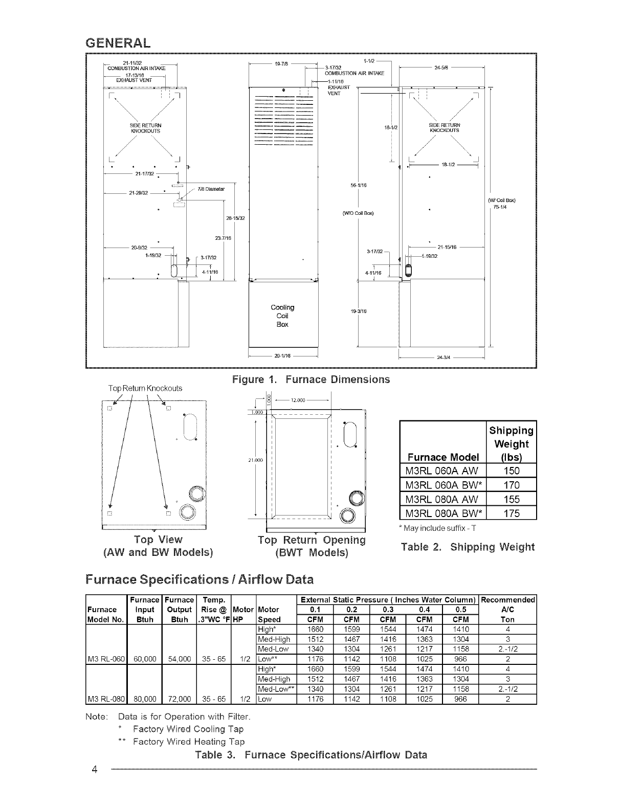
Figure 1. Furnace Dimensions
_12.000_
1000
21000
O
=©
Top Returr_ Opening
(BWT Models)
Furnace Model
M3RL 060A AW
M3RL 060A BW*
M3RL 080A AW
M3RL 080A BW*
* May include suffix - T
Table 2.
Shipping
Weight
(Ibs)
15O
170
155
175
Shipping Weight
Furnace Specifications /Airflow Data
Furnace Furnace Temp.
Furnace Input Output Rise @ Motor
Model No. Btuh Btuh .3"WC °F HP
M3 RL-060 60,000 54,000 35- 65 I/2
M3 RL-080
Note:
80,000 72,000 35 - 65 I/2
External Static Pressure ( Inches Water Column) Recommended
Motor 0.1 0.2 0.3 0.4 0.5 A/C
Speed CFM CFM CFM CFM CFM Ton
High* 1660 I599 I544 1474 I410 4
Med-High 1512 I467 I416 1363 I304 3
Med-Low 1340 I304 I261 1217 II58 2.-I/2
Low** 1176 II42 I108 1025 966 2
High* 1660 I599 I544 1474 I410 4
Med-High 1512 I467 I416 1363 I304 3
Med-Low** 1340 I304 I261 1217 II58 2.-I/2
Low 1176 II42 I108 1025 966 2
Data is for Operation with Filter,
* Factory Wired Cooling Tap
** Factory Wired Heating Tap
Table 3. Furnace SpecificationslAirflow Data
WARNmNG:
Do not use this appmiance if any part
has been submerged underwater. Im-
mediatemy camsa quamified service tech-
nician to inspect the appmiance and to
repmace any part of the controm system
and any gas controm that has been
submerged underwater.
NOTICE TO iNSTALLER
Installer is advised to follow carefully all instruc-
tions and warnings in this manual to insure
maximum performance, safety, and operating
efficiency of these appliances. Improper installa-
tion may create hazardous conditions, and will
void the appliance warranty.
GENERAL
General Description
The M3 series gas furnaces are listed direct
vent (sealed combustion) forced air furnaces
for use with both natural and propane gases.
The M3 series is a Category IV and type FSP
furnace. The M3 furnace series has been
certified to the ANSi Z21.47/CSA2.%2001 for
use in the United States and Canada and to the
UL307B --1995 for use in the United States.
These furnaces may be installed in:
I. Manufactured Homes.
2. Park Models and Manufactured buildings
3. Modular Homes/Buildings
The following are safety guidelines with refer-
ences to their specific sections or pages in the
manual.
I. Use only type of gas approved for this
furnace. Refer to the furnace rating plate.
2. Install this furnace only in location and
position as specified in pages 7 - 13 of
these instructions.
3. Provide adequate combustion and ventila-
tion air to the furnace space as specified in
pages 13 - 20 of these instructions.
4. Combustion products must be discharged
outdoors, connect this furnace to an ap-
proved vent system only, as specified in
pages 14-19 of these instructions.
5. Never test for gas leaks with an open
flame. Use a commercially available soap
solution made specifically for the detection
of leak to check all connections.
6. Always install furnace to operate within the
furnace's intended temperature rise range
with a duct system that has an external
static pressure within the allowable range,
as specified in page 4 of these instruc-
tions. See furnace rating plate.
7. When a furnace is installed so that supply
ducts carry air circulated by the furnace to
areas outside the space containing the
furnace, the return air shall also be handled
by duct(s) sealed to the furnace casing
and terminating outside the space contain-
ing the furnace. Note: This section only
applies to furnaces installed with side or
top return air.
8. A gas-fired furnace for installation in a
residential garage must be installed as
specified in page 7 of these instructions.
9. The furnace is not to be used for tempo-
rary heat of buildings or structures under
construction.
M3 series furnaces are air conditioning ready
as shipped. The furnace cooling capacities of
the blower motor speed taps are shown in
Table 3. Table 2 lists the shipping weights for
the M3 series furnaces.
OWNER NFORMATION
NORDYNE has been involved in the design of
products for the manufactured home industry
since the first manufactured home or trailer
was built.
NORDYNE originated the sealed combustion
system, which separates the furnace com-
bustion system from the living area of the
home, now a standard for the manufactured
home industry.
NORDYNE engineers developed the first cen-
tral heating system and the first central air
conditioner for manufactured homes.
NORDYNE is dedicated to bringing to its cus-
tomers the finest heating and cooling comfort
possible. NORDYNE constantly seeks to fur-
ther refine its products to continuously provide
exceptional comfort.
Followtheinstructionsinthisbookletcarefully
andthisappliancewillprovidemanyyearsof
superiorperformance.
if youwish to cool yourhomeautomatically
witha centralair conditioningsysteminvesti-
gatetheexcellentNORDYNEcoolingsystems
availablefromyour heatingand coolingcon-
tractor.Thesesystemsare designedto work
bestwithyour NORDYNEfurnaceand have
beencarefullyengineeredto deliveroptimum
performancewhen mated with NORDYNE
manufacturedhomefurnaces.
NORDYNEalsoofferswaterheaters,fireplaces
and ventilatingsystemsspecificallydesigned
for manufacturedhousingapplications.Check
with your manufacturedhomeretailer,your
heating and cooling contractor or your
distributorfor information.Writedirectlyto the
factory(POBox8809,O'Fallon,MO63366)if
youarenotabletolocateasourceforNORDYNE
manufacturedhousingproductsin yourarea.
MANUFACTURERWARRANTY,OWNER'S
RESPONSIBILITIES
it isthesoleresponsibilityofthehomeownerto
makecertainthegasfurnacehasbeencorrectly
setupandconvertedtotheproperfuel(UP.gas
or Naturalgas)andadjustedto operateprop-
erly. All gas furnacesare manufacturedfor
Naturalgasandmustbefieldconvertedwhen
usingUP.gas.
Awarrantycertificatewithfulldetailsisincluded
withtheseinstructions.However,NORDYNE
willnotberesponsibleforanycostsfoundnec-
essaryto correctproblemsdue to improper
setup,improperinstallation,furnaceadjustments,
improperoperatingprocedureonthepartofthe
user,etc.
Somespecificexamplesof servicecallswhich
cannotbeincludedinwarrantypaymentsare:
I. Convertingthefurnacetouseanothertype
ofgas.
2. Repairingductworkinthehomefoundtobe
faulty.
3. Correctingwiringproblemsintheelectrical
circuitsupplyingthefurnace.
4. Resettingcircuitbreakers,blownfusesor
otherswitches.
5. Correctingproblemsdueto impropergas
supplypressuretothefurnace.
6. Providinginstructionaltrainingon how to
lightandoperatethefurnace.
7. Furnaceproblemscausedbyinstallationof
anair conditioner,heatpumpor otherair
comfortdevices.
8. Revisinginstallationof the furnaceflue
assembly.
9. Adjustingor calibratingof thermostat.
10.Any constructiondebriswhich falls into
thefluesystem.
Carefullyreviewtheseresponsibilitieswithyour
manufacturedhousingdealer,servicecompany
or gassupplierso therewill beno misunder-
standingat alatertime.
CAUTmON'.
Never attempt to alter or modify this
furnace or any of its components.
Never attempt to repair damaged or
inoperable components. Such action
could cause unsafe operation, ex-
plosion, fire and/or asphyxiation.
• If a malfunction has occurred, or if
you feel that the furnace is not oper-
ating as it should, contact a qualified
service agency or gas utility for as-
sistance.
iNSTALLATiON STANDARDS
Installer shall be familiar with and comply with all
codes and regulations applicable to the installa-
tion of these heating appliances and related
equipment. In lieu of local codes, the installation
shall be in accordance with the current provi-
sions of one or more of the following standards.
a. Federal Manufactured Home Constructions
& Safety Standard (H.U.D. Title 24, Part
3280.707[a][2])
b. The Standard for Manufactured Home Instal-
lations (Manufactured Home Sites, Commu-
nities, and Set-Ups) ANSI A225.1 and/or
CAN/CSA-2240 MH Series).
c. American National Standard (ANS1-119.2/
NFPA-501C) for all recreational vehicle in-
stallations.
d. American National Standard (ANSI-Z223.1/
NFPA-54) and/or CAN/CGA B149 for all gas-
fired furnace models.
e. American National Standard (ANSI-C1iNFPA-
70) and/or CSA 22. I Canadian Electric Code
Part I for all electrical field wiring.
CE gen6rateurd'air chauddoit 6tre installe
conformementauxinstructionsdufabricantet
auxcodesIocaux.EnI'absencedecodelocal,
respecterlanormeANSIZ223.,I,instituleNa-
tionalFuelGasCodeoulescodesd'installation
CAN/GCA-B149.
The NationalFuelGas Codeis availableby
writing:
AmericanNationalStandardsinstitute,inc.
1430 Broadway
NewYork,NY10018
NFPApublicationsareavailablebywriting:
NationalFireProtectionAssociation
BatterymarchPark
Quincy,ME02269
LOCATION
The furnace must be installed on a level suF
face, and as close to the center of the air
distribution system as possible. See Figure I
for overall dimensions to determine the re-
quired clearances in hallways, doorways,
stairs, etc. to allow the furnace to be moved to
the installation point. The furnace must be in-
stalled so that all electrical components are
protected from water.
Minimum clearances to combustible materials
are listed in Table 4. Access for positioning and
servicing must be considered when locating
the unit.
This furnace is certified for use on wood
flooring. The furnace must be installed on a
solid surface and must be level front4o-back
and side-to-side. This furnace must not be
installed directly on carpeting, tile, or any com-
CLOSET ALCOVE
ALL MODELS Inches Inches
Front
Back
Sides
Vent
Top
Duct (Plenum)
w/Coil Box
w/o Coil Box
(within 3 feet)
1" 1"
0 0
0 0
0 0
6 6
0 0
1/4 1/4
*Note: For 1"clearance, use a fullylouvered door with at
least 400 square inches of free airflow area.
Table 4. Minimum Clearances
bustible material other than wood flooring. The
furnace may be installed on combustible floor-
ing when installed on a Nordyne duct connec-
tor (see Table 5).
The ductwork within 3 feet of the furnaces
without the A/C coil box must be installed such
that surfaces are at least I/4" from combustible
materials.
When installed in a residential garage, the fur-
nace must be positioned so the burners and the
source of the ignition are located no less than
18 inches above the floor and protected from
physical damage by vehicles.
CiRCULATiNG AiR SUPPLY
WARNmNG:
Products of combustion must not be
allowed to enter the return air openings
of the furnace or the circulating air
supply. Failure to prevent products of
combustion from being circulated into
the living space can create potentially
hazardous conditions including carbon
monoxide poisoning that could result in
personal iniury or death.
The floor or platform on which the
furnace is mounted must provide sound
physical support of the furnace with no
gaps, cracks, or sagging between the
furnace and the floor or platform.
The circulating air ductwork must not
be connected to any other heat
producing device such as a fireplace
insert, stove, etc.
GENERAL
Plenums and air ducts must be installed in
accordance with the Standard for the Installa-
tion of Air Conditioning and Ventilating Systems
(NFPA No. 90A) or the Standard for the Instal-
lation of Warm Air Heating and Air Conditioning
Systems (NFPA No. 90B).
RETURN AiR PROViSiONS
U.S.A. home manufacturers shall comply with
aft of the following conditions to have accept=
able return air systems for closet installed
forced air heating appliances:
a. Regardless of the location, the return air
opening into the closet shall not be less than
specified in the appliance's listing.
b. Means shall be provided to prevent inadverb
ent closure by a flat object placed over the
return air opening when it is located in the
floor of the closet (versus the vertical front
or side wall).
c. Closet installations must use a Iouvered
door having a minimum free area of 235 sq.
in. when located 6" from furnace. For clear=
ance between I" and 6" from furnace, re-
quirements are a Iouvered door with mini-
mum of 235 sq. in. free area, with the open=
ings in closet door directly inJine with the
Iouvered openings in the furnace door. For
I" clearance from furnace, use a fully Iou-
vered door with at least 400 sq. in. of free
airflow area.
d. The cross-sectional area of the return duct
system leading into the closet, when located
ASingle trunk duct
,
/Dual trunk duct
B w/crossover connector
I
I
I
Transition duct
C pw/branches _
U U
Figure 2. Non=Platinum
Supply Duct System
inthe floor or ceiling shall not be less than 235
square inches.
e. The total free area of openings in the floor or
ceifing registers serving the return air duct
system must be at least 352 sq. in. At least
one register should be located where it is not
likely to be covered by carpeting, boxes and
other objects.
f. Materials located in the return duct system
must have a flame spread classification of
200 or less. This includes a closet door if the
furnace is in a closet.
g. Noncombustible pans having I" upturned
flanges are located beneath openings in a
floor duct system.
h. Wiring materials located in the return duct
system shall conform to Articles 300=22 of
the National Electrical Code (ANSI CI/
NFPA=70).
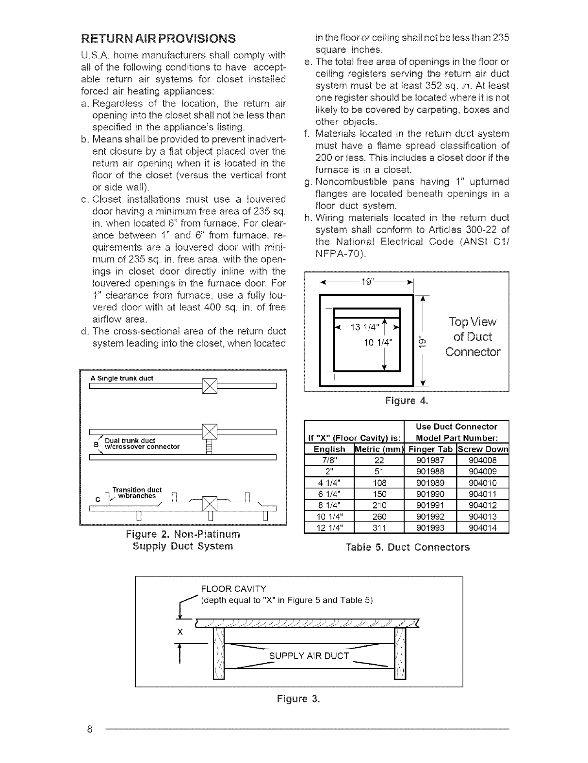
19"_ I
I_13 1/4'_
10 1/4"
I
k
Top View
_, of Duct
"_ Connector
Figure 4.
Use Duct Connector
If "X" (Floor Cavity) is: Model Part Number:
English Metric (mm I Finger Tab Screw Down
7/8" 22 901987 904008
2" 51 901988 904009
4 1/4" 108 901989 904010
6 1/4" 150 901990 904011
8 1/4" 210 901991 904012
10 1/4" 260 901992 904013
12 1/4" 311 901993 904014
Table 5. Duct Connectors
FLOOR CAVITY
Z(depth equal to "X" in Figure 5 and Table 5)
X i, "1
I I:/ SUPPLY AIR DUCT
/
/(
Figure 3.
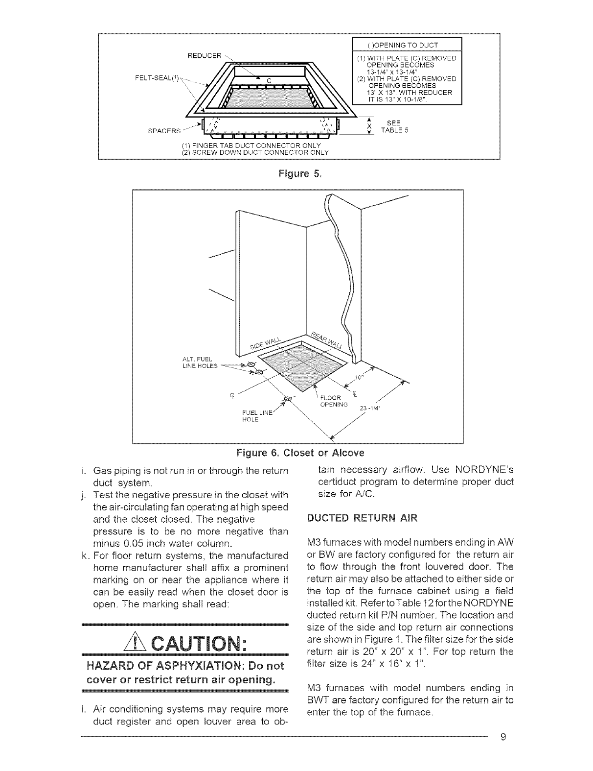
( )OPENING TO DUCT
(1) WITH PLATE (C) REMOVED
OPENING BECOMES
13-1/4" x 13-1/4"
(2) WITH PLATE (C) REMOVED
OPENING BECOMES
13"X 13" WITH REDUCER
ITIS 13"X 10-1/8"
SPACERS -m . E • I • I • I •-
(1) FINGER TAB DUCT CONNECTOR ONLY
(2) SCREW DOWN DUCT CONNECTOR ONLY
A
X SEE
y TABLE 5
Figure 5.
ALTFUEL
FUEL
HOLE
Figure 6. Closet or Alcove
i. Gas piping is not run in or through the return
duct system.
j. Test the negative pressure in the closet with
the air-circulating fan operating at high speed
and the closet closed. The negative
pressure is to be no more negative than
minus 0.05 inch water column.
k. For floor return systems, the manufactured
home manufacturer shall affix a prominent
marking on or near the appliance where it
can be easily read when the closet door is
open. The marking shall read:
HAZARD OF ASPHY×IATmON: Do not
cover or restrict return air opening.
I. Air conditioning systems may require more
duct register and open louver area to ob-
tain necessary airflow. Use NORDYNE's
certiduct program to determine proper duct
size for AiC.
DUCTED RETURN AIR
M3 furnaces with model numbers ending in AW
or BW are factory configured for the return air
to flow through the front Iouvered door. The
return air may also be attached to either side or
the top of the furnace cabinet using a field
installed kit. Refer toTable 12 for the NORDYNE
ducted return kit PiN number. The location and
size of the side and top return air connections
are shown in Figure I. The filter size for the side
return air is 20" x 20" x I". For top return the
filter size is 24" x 16" x I".
M3 furnaces with model numbers ending in
BWT are factory configured for the return air to
enter the top of the furnace.
2-1/4
14-1/2
21-3/4
3-I14
1-1/4
ALT FUEL LINE
ENTRY
I
I
FLOOR CUT-OUT
FOR DUCT CONNECTIONS
I
12-7/8
15-1/2
FLOOR CUT-OUT
FOR OPTIONAL
COOLING COIL
FOR NON-PLATINUM
SERIES UNITS
8-19/32
1-3/4
f VENT
COMBUSTION AiR INTAKE
FUEL LINE ENTRY
1-3/4
OUTER DOOR
17-29/32
21-7/16
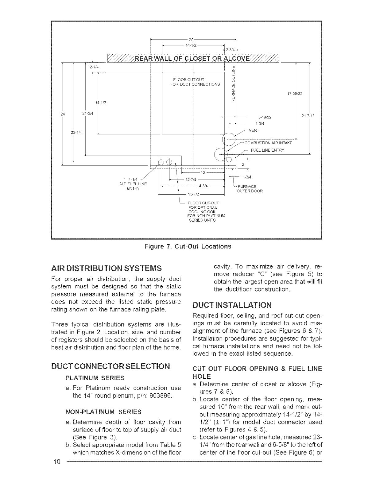
Figure 7. Cut-Out Locations
NR DiSTRiBUTiON SYSTEMS
For proper air distribution, the supply duct
system must be designed so that the static
pressure measured external to the furnace
does not exceed the listed static pressure
rating shown on the furnace rating plate.
Three typical distribution systems are illus-
trated in Figure 2. Location, size, and number
of registers should be selected on the basis of
best air distribution and floor plan of the home.
DUCT CONNECTOR SELECTION
PLATINUM SERES
a. For Platinum ready construction use
the 14" round plenum, pin: 903896.
I0
NON-PLATINUM SERIES
a. Determine depth of floor cavity from
surface of floor to top of supply air duct
(See Figure 3).
b. Select appropriate model from Table 5
which matches X-dimension of the floor
cavity. To maximize air delivery, re-
move reducer "C" (see Figure 5) to
obtain the largest open area that will fit
the duct/floor construction.
DUCT iNSTALLATiON
Required floor, ceiling, and roof cut-out open-
ings must be carefully located to avoid mis-
alignment of the furnace (see Figures 6 & 7).
installation procedures are suggested for typi-
cal furnace installations and need not be fol-
lowed in the exact listed sequence.
CUT OUT FLOOR OPENING & FUEL LINE
HOLE
a. Determine center of closet or alcove (Fig-
ures 7 & 8).
b. Locate center of the floor opening, mea-
sured 10" from the rear wall, and mark cut-
out measuring approximately 14-I/2" by 14-
I/2" (+ I") for model duct connector used
(refer to Figures 4 & 5).
c. Locate center of gas line hole, measured 23-
I/4" from the rear wall and 6-5/8" to the left of
center of the floor cut-out (See Figure 6) or
5-I/4"totheleftofcenterofthefloorcut-out,
or for entrythroughright-sideof furnace
measured9"totherightofcenterofthefloor
cut-out.
d. Cutoutflooropeningandonegaslinehole.
CUT DUCTOPENING(FINGERTABBED
ONLY)
a. Placeductconnectorthroughtheflooropen-
ing withbottomtabsrestingon top of the
supplyairduct.
b. Centerductconnectorandpushbackagainst
rearedgeofflooropening.
c. Markcut-outlocation(tabarea)andremove
duct connector.
d. Cutoutductopening1/16"largerthanarea
marked.
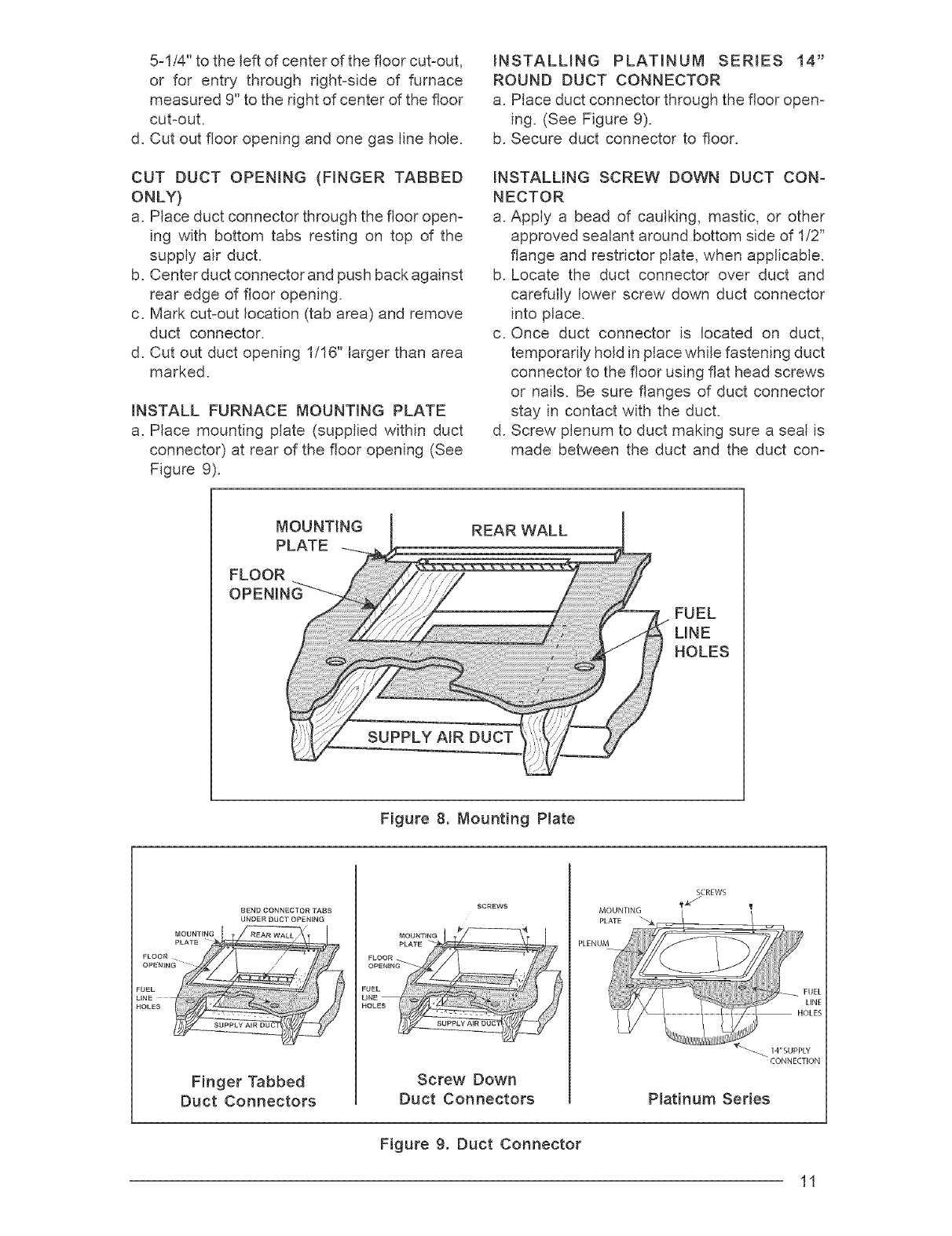
INSTALLFURNACEMOUNTINGPLATE
a. Placemountingplate(suppliedwithinduct
connector)at rearof theflooropening(See
Figure9).
INSTALLING PLATINUM SERIES 14"
ROUNDDUCTCONNECTOR
a. Placeductconnectorthroughtheflooropen-
ing.(SeeFigure9).
b. Secureductconnectorto floor.
INSTALLINGSCREWDOWNDUCTCON-
NECTOR
a.Applya beadof caulking,mastic,or other
approvedsealantaroundbottomsideof I/2"
flangeandrestrictorplate,whenapplicable.
b. Locatethe duct connectoroverduct and
carefullylowerscrewdownductconnector
intoplace.
c. Onceduct connectoris locatedon duct,
temporarilyholdinplacewhilefasteningduct
connectorto thefloorusingflatheadscrews
or nails.Besureflangesof ductconnector
stayincontactwiththeduct.
d. Screwplenumto ductmakingsureasealis
madebetweenthe ductandtheduct con-
MOUNTING REARWALL
FUEL
LINE
HOLES
Figure 8. MountingPlate
BEND CONNEC _OR TABS
UNDER DUCT OPENING
Finger Tabbed
Duct Connectors
Screw Down
Duct Connectors
MOUNTING
SCREWS
CONNECTION
Platinum Series
Figure 9. Duct Connector
11
nector.Additionalscrewsmaybe addedif
required.
e. Cutawayalongedgeof flangeallowingthe
centertodropintotheduct.Removesection
ofductwithcaution,asedgeswillbesharp.
INSTALLINGFINGERTABBEDDUCTCON-
NECTORS
a. Placeductconnectorthroughtheflooropen-
ingwithbottomtabsextendingthroughthe
ductopening.(SeeFigure9)
b. Secureductconnectorto floor.
c. Bendbottomtabsunderanduptightlyagainst
thesupplyair duct(SeeFigure10).
NOTE:Theductconnectorisdesignedforuse
onducts12"inwidth.Whenusingtheconnec=
toron12"wideducts,theremaybeinsufficient
clearanceto bendthetabsontwosidesof the
ductconnector,insuchcasesthetabsmaybe
attachedtothesidesoftheductbyusingsheet
metalscrewsor othersuitablefasteners.(See
Figure11).
if sealant,mastic,ortapeisusedto providea
betterseal,itshouldbeapprovedbyapplicable
nationalor localcodes.
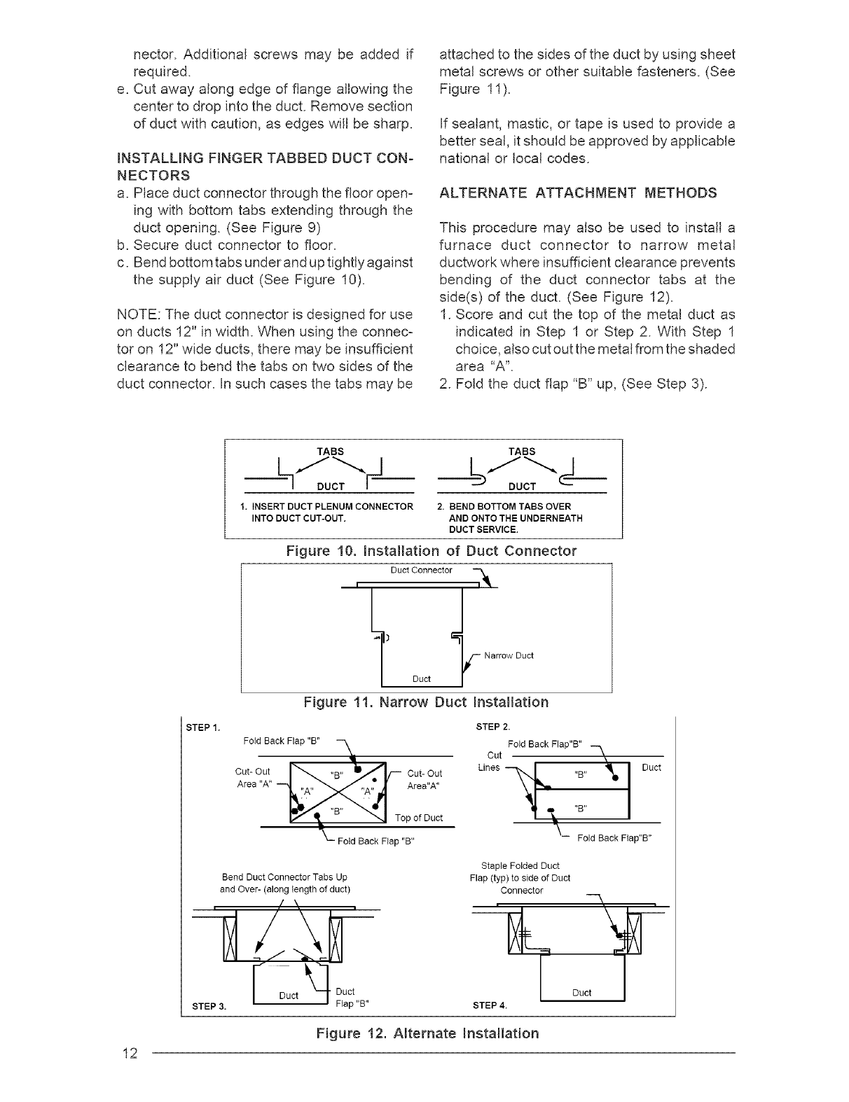
ALTERNATEATTACHMENTMETHODS
Thisproceduremayalsobeusedto installa
furnace duct connector to narrow metal
ductworkwhereinsufficientclearanceprevents
bendingof the duct connectortabs at the
side(s)of theduct.(SeeFigure12).
I. Scoreandcutthetopof themetalductas
indicatedin StepI or Step2. WithStepI
choice,alsocutoutthemetalfromtheshaded
area"A'.
2. Foldtheductflap"B"up,(SeeStep3).
12
STEP 1.
TABS TABS
DUCT _ DUCT
1. INSERT DUCTPLBNUM CONNECTOR 2. BEND BOTTOM TABS OVER
INTO DUCT CUT-OUT. AND ONTO THE UNDERNEATH
DUCTBERVtCE.
Figure 10. Installation of Duct Connector
Duct Connector i_
I
_) Duct
Figure 11. Narrow Duct Installation
_ Narrow Duct
Fold Back Flap "B"
Cut- Out Cut- Out
Area"A"
Top of Duct
Fold Back Flap "B"
STEP 2.
Fold Back Flap"B"
Cut
-- Fold Back Flap"B"
Bend Duct Connector Tabs Up
and Over- (along length of duct)
, ,/ \, ,
// "_k_ !LtC t
Staple Folded Duct
Flap (typ) to side of Duct
Connector .
_L_ Duct _--'_
STEP 4.
Figure 12. Alternate Installation
NOTE:Additionalfastenersmaybe usedat
rear,sidesor throughdoorframe,asdesired,
to securefurnaceto closetor alcoveframing.
VENTING AND COMBUSTION AiR
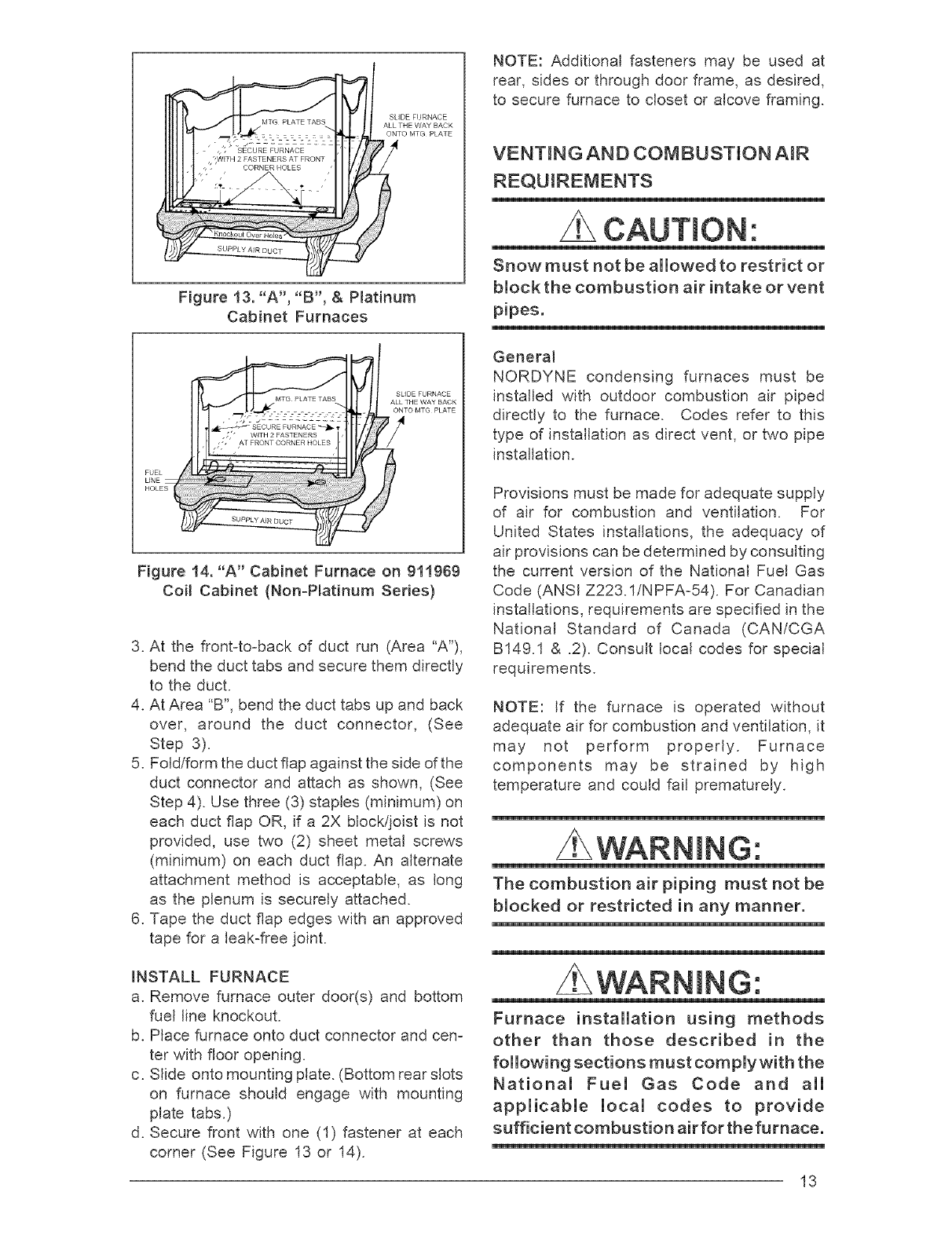
Figure 13. "A', "g', & Platinum
Cabinet Furnaces
SLIDE FURNACE
ALL THE WAY BACK
ONTO MTG PLATE
SECURE FURNACE _ q, -
•[, ' WFH 2 FASTENERS , ,
,', AT FRONT CORNER HOLES ' '
HOLES
Figure 14. "A" Cabinet Furnace on 911969
Coil Cabinet (NonoPmatinum Series)
3. At the front-to-back of duct run (Area "A'),
bend the duct tabs and secure them directly
to the duct.
4. At Area "B", bend the duct tabs up and back
over, around the duct connector, (See
Step 3).
5. Fold/form the duct flap against the side of the
duct connector and attach as shown, (See
Step 4). Use three (3) staples (minimum) on
each duct flap OR, if a 2X block/joist is not
provided, use two (2) sheet metal screws
(minimum) on each duct flap. An alternate
attachment method is acceptable, as long
as the plenum is securely attached.
6. Tape the duct flap edges with an approved
tape for a leak-free joint.
_NSTALL FURNACE
a. Remove furnace outer door(s) and bottom
fuel line knockout.
b. Place furnace onto duct connector and cen-
ter with floor opening.
c. Slide onto mounting plate. (Bottom rear slots
on furnace should engage with mounting
plate tabs.)
d. Secure front with one (1) fastener at each
corner (See Figure 13 or 14).
CAUTmON'.
Snow must not be allowed to restrict or
block the combustion air intake or vent
pipes.
General
NORDYNE condensing furnaces must be
installed with outdoor combustion air piped
directly to the furnace. Codes refer to this
type of installation as direct vent, or two pipe
installation.
Provisions must be made for adequate supply
of air for combustion and ventilation. For
United States installations, the adequacy of
air provisions can be determined by consulting
the current version of the National Fuel Gas
Code (ANSI Z223.1iNPFA-54). For Canadian
installations, requirements are specified in the
National Standard of Canada (CAN/CGA
B149.1 & .2). Consult local codes for special
requirements.
NOTE: If the furnace is operated without
adequate air for combustion and ventilation, it
may not perform properly. Furnace
components may be strained by high
temperature and could fail prematurely.
G:
The combustion air piping must not be
blocked or restricted in any manner.
WARNmNG:
Furnace installation using methods
other than those described in the
following sections must complywith the
National Fuel Gas Code and all
applicable local codes to provide
sufficient combustion air for the furnace.
13
Do not allow debris to fail into the fur-
nace. This could cause unsafe opera-
tion and voids the furnace warranty.
VENTING REQUIREMENTS
WARNmNG:
FURNACE MUST NOT BE COMMON
VENTED WiTH OTHER APPLIANCES.
Genera_
This section specifies installation requirements
for 2-pipe combustion air piping. The capacity
table provided in this section applies to the
maximum equivalent lengths of vent and
combustion air intake pipe.
These condensing furnaces are classified as
"Category IV" appliances, which require
special venting materials and installation
procedures. Category tV appliances operate
with positive vent pressure and therefore
require vent systems which are thoroughly
sealed. They also produce combustion
condensate, which is slightly acidic and can
cause severe corrosion of ordinary venting
materials. Furnace operation can be adversely
affected by restrictive vent and combustion
air piping. Therefore, vent and combustion air
piping lengths must conform completely to the
requirements of Table 6.
The furnace must be vented to the outdoors.
WARNmNG:
CARBON MONOXmDE POiSONmNG
HAZARD
1. Seal any unused openings in the
venting system
2. inspect the venting system for
proper size and horizontal pitch,
as required in the National Fuel
Gas Code, ANSI Z223.1 or the
CAN/OGA Bt49 mnstallation Codes
and these instructions. Determine
that there is no blockage or re-
striction, leakage, corrosion and
other deficiencies which could
cause an unsafe condition.
3. So far as is practical, close all
building doors and windows and
all doors between the space in
which the appliance(s) connected
to the venting system are located
and other spaces of the building.
4. Follow the lighting instructions.
Place the appliance being
inspected in operation. Adjust
thermostat so appliance shall
operate continuously.
5. Turn on clothes dryers and any
other appliance not connected to
the venting system. Turn on any
exhaust fans, such as range hoods
and bathroom exhausts, so they
shall operate at maximum speed.
Do not operate a summer exhaust
fan.
6. Close fireplace dampers.
7. Test for spillage from draft hood
equipped appliance at the draft
hood relief opening after 5 minutes
of main burner operation. Use the
flame of a match or candle.
8. if improper venting is observed
during any of the above tests, the
venting system must be corrected
in accordance with the National
Fuel Gas Code, ANSt Z223.1/NFPA
54 an d/or CSA B I49.1, Natural Gas
and Propane Installation Codes.
9. After it has been determined that
each appliance connected to the
venting system properly vents
when tested as outlined above,
return doors, windows, exhaust
fans, fireplace dampers and any
other gas burning appliance to
their previous conditions of use.
It must not be vented in common with any
other appliance, even if that appliance is of the
condensing type. Common venting can result
in severe corrosion of other appliances or their
venting and can allow combustion gases to
14
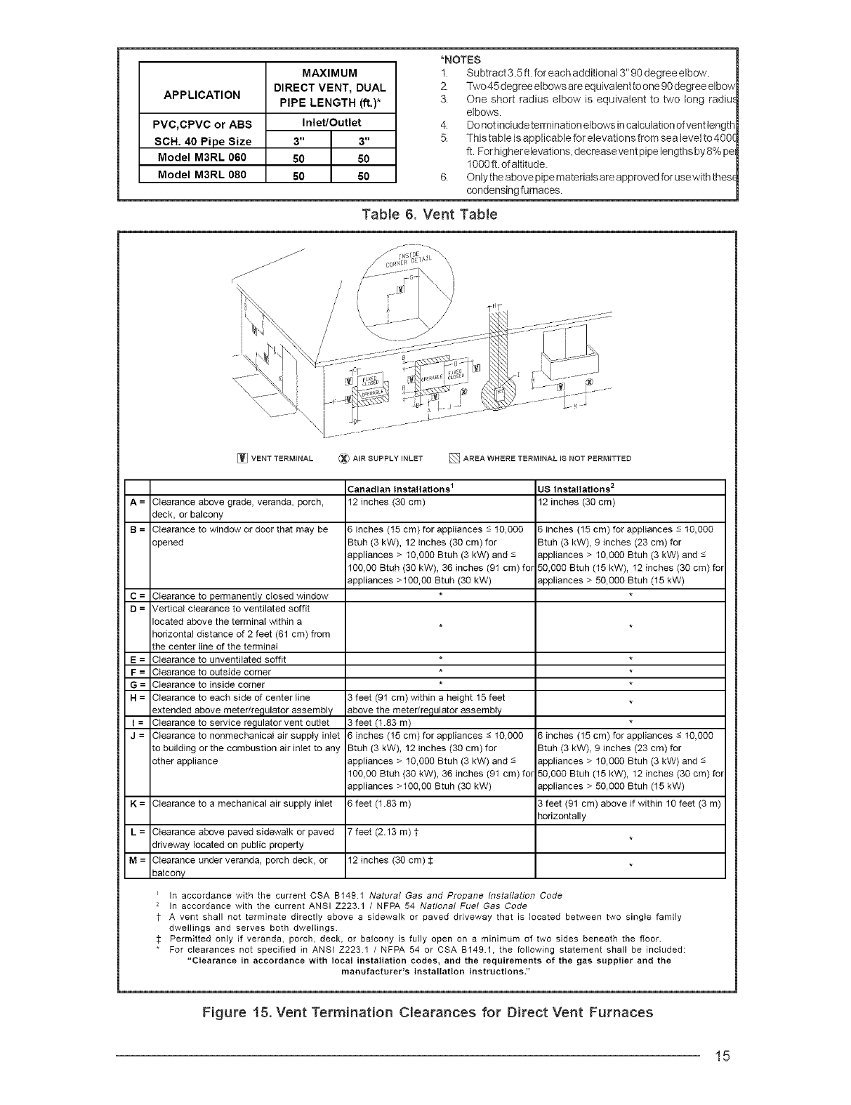
APPLICATION
PVC,CPVC or ABS
SCH. 40 Pipe Size
Model M3RL 060
Model M3RL 080
MAXIMUM
DIRECT VENT, DUAL
PIPE LENGTH (ft.)*
Inlet/Outlet
3" 3"
50 50
50 50
*NOTES
1. Subtract 3.5 ft. for each additional 3" 90 degree elbow.
2. Two45degree elbowsare equivalent toone 90degree elbow
3 One short radius elbow is equivalent to two long radiu,_
elbows.
4. Do not include terrnination elbows incalculation of vent length
5 This table is applicable for elevations from sea levelto 400(
ft. Forhigher elevations, decreasevent pipe lengthsby 8% pe
1000 ft. of altitude
6 Only the above pipematerialsare approved for usewith thes(
condensing furnaces.
Tabie 6. Vent Tabie
/
/
/
/
/
/
_J VENT TERMINAL (_ AiR SUPPLY INLET [] AREA WHERE TERMINAL iS NOT PERMITTED
A = Clearance above grade, veranda, porch,
deck, or balcony
B = Clearance to window or door that may be
opened
C = Clearance to permanently closed window
D=Vertical clearance to ventilated soffit
located above the terminal within a
horizontal distance of 2 feet (61 cm) from
the center tine of the terminal
E = Clearance to unventilated soffit
F = Clearance to outside corner
G = Clearance to inside corner
H = Clearance to each side of center tine
extended above meter/regulator assembly
I = Clearance to service regulator vent outlet
J = Clearance to nonmechanicaI air supply inlet
to building or the combustion air inlet to any
other appliance
Canadian Installations 1
12 inches (30 cm)
K = Clearance to a mechanical air supply inlet
L = Clearance above paved sidewatk or paved 7 feet (2.13 m) 1
driveway located on public property
M= Clearance under veranda, porch deck, or 12 inches (30 cm) $
balcony
6 inches (15 cm)for appliances -< 10,000
Btuh (3 kW), 12 inches (30 cm) for
appliances > 10,000 Btuh (3 kW) and -<
100,00 Btuh (30 kW), 36 inches (91 cm) for
appliances >100,00 Btuh (30 kW)
3 feet (91 cm) within a height 15 feet
above the meter/regulator assembly
3 feet (1.83 m)
6 inches (15 cm)for appliances -< 10,000
Btuh (3 kW), 12 inches (30 cm)for
appliances > 10,000 Btuh (3 kW) and -<
100,00 Btuh (30 kW), 36 inches (91 cm) for
appliances >100,00 Btuh (30 kW)
6 feet (1.83 m)
US Installations 2
12 inches (30 cm)
6 inches (15 cm)for appliances -<10,000
Btuh (3 kW), 9 inches (23 cm) for
appliances > 10,000 Btuh (3 kW) and -<
50,000 Btuh (15 kW), 12 inches (30 cm) fol
appliances > 50,000 Btuh (15 kW)
6 inches (15 cm)for appliances -<10,000
Btuh (3 kW), 9 inches (23 cm) for
appliances > 10,000 Btuh (3 kW) and -<
50,000 Btuh (15 kW), 12 inches (30 cm) fol
appliances > 50,000 Btuh (15 kW)
3 feet (91 cm) above if within 10 feet (3 m)
horizontally
In accordance with the current CSA B149.1 Natural Gas and Propane Installation Code
2 In accordance with the current ANSI Z223.1 /NFPA 54 National Fuel Gas Code
1 A vent shall not terminate directly above a sidewalk or paved driveway that is located between two single family
dwellings and serves both dweltings
_: Permitted only if veranda, porch, deck, or balcony is fully open on a minimum of two sides beneath the floor.
* For clearances not specified in ANSI Z223.! /NFPA 54 or CSA B149.1, the following statement shall be included:
"Clearance in accordance with local installation codes, and the requirements of the gas supplier and the
manufacturer's installation instructions."
Figure 15. Vent Termination Clearances for Direct Vent Furnaces
15
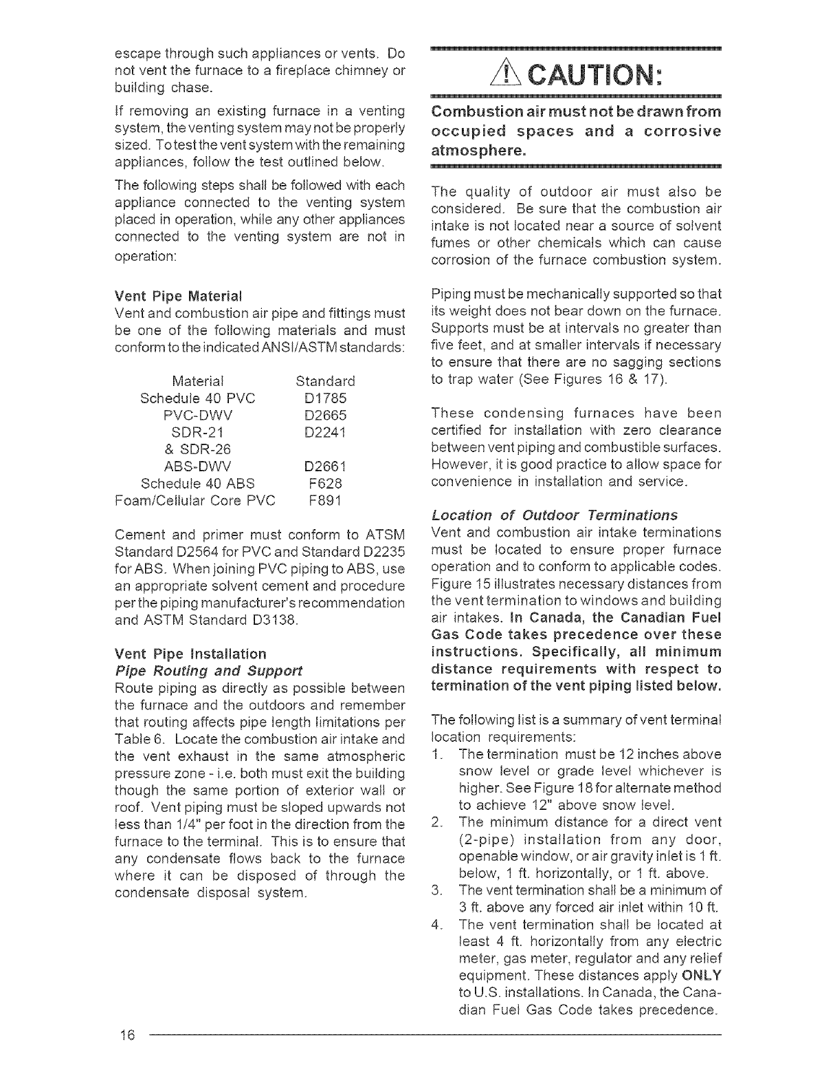
escapethroughsuchappliancesorvents. Do
notventthefurnaceto afireplacechimneyor
buildingchase.
if removingan existingfurnacein a venting
system,theventingsystemmaynotbeproperly
sized.Totesttheventsystemwiththeremaining
appliances,followthetestoutlinedbelow.
CAUTmON'.
Combustion air must not be drawn from
occupied spaces and a corrosive
atmosphere.
The following steps shall be followed with each
appliance connected to the venting system
placed in operation, while any other appliances
connected to the venting system are not in
operation:
The quality of outdoor air must also be
considered. Be sure that the combustion air
intake is not located near a source of solvent
fumes or other chemicals which can cause
corrosion of the furnace combustion system.
Vent Pipe Material
Vent and combustion air pipe and fittings must
be one of the following materials and must
conform to the indicated ANSI/ASTM standards:
Material Standard
Schedule 40 PVC D1785
PVC-DWV D2665
SDR-21 D2241
& SDR-26
ABS-DWV D2661
Schedule 40 ABS F628
Foam/Cellular Core PVC F891
Cement and primer must conform to ATSM
Standard D2564 for PVC and Standard D2235
for ABS. When joining PVC piping to ABS, use
an appropriate solvent cement and procedure
per the piping manufacturer's recommendation
and ASTM Standard D3138.
Vent Pipe Installation
Pipe Routing and Support
Route piping as directly as possible between
the furnace and the outdoors and remember
that routing affects pipe length limitations per
Table 6. Locate the combustion air intake and
the vent exhaust in the same atmospheric
pressure zone - i.e. both must exit the building
though the same portion of exterior wall or
roof. Vent piping must be sloped upwards not
less than 1/4" per foot in the direction from the
furnace to the terminal. This is to ensure that
any condensate flows back to the furnace
where it can be disposed of through the
condensate disposal system.
Piping must be mechanically supported so that
its weight does not bear down on the furnace.
Supports must be at intervals no greater than
five feet, and at smaller intervals if necessary
to ensure that there are no sagging sections
to trap water (See Figures 16 & 17).
These condensing furnaces have been
certified for installation with zero clearance
between vent piping and combustible surfaces.
However, it is good practice to allow space for
convenience in installation and service.
Location of Outdoor Terminations
Vent and combustion air intake terminations
must be located to ensure proper furnace
operation and to conform to applicable codes.
Figure 15 illustrates necessary distances from
the vent termination to windows and building
air intakes. In Canada, the Canadian Fue!
Gas Code takes precedence over these
instructions. Specifically, all minimum
distance requirements with respect to
term!nation of the vent piping listed below.
The following list is a summary of vent terminal
location requirements:
I. The termination must be 12 inches above
snow level or grade level whichever is
higher. See Figure 18 for alternate method
to achieve 12" above snow level.
2. The minimum distance for a direct vent
(2-pipe) installation from any door,
openable window, or air gravity inlet is I ft.
below, 1 ft. horizontally, or 1 ft. above.
3. The vent termination shall be a minimum of
3 ft. above any forced air inlet within 10 ft.
4. The vent termination shall be located at
least 4 ft. horizontally from any electric
meter, gas meter, regulator and any relief
equipment. These distances apply ONLY
to U.S. installations, in Canada, the Cana-
dian Fuel Gas Code takes precedence.
16
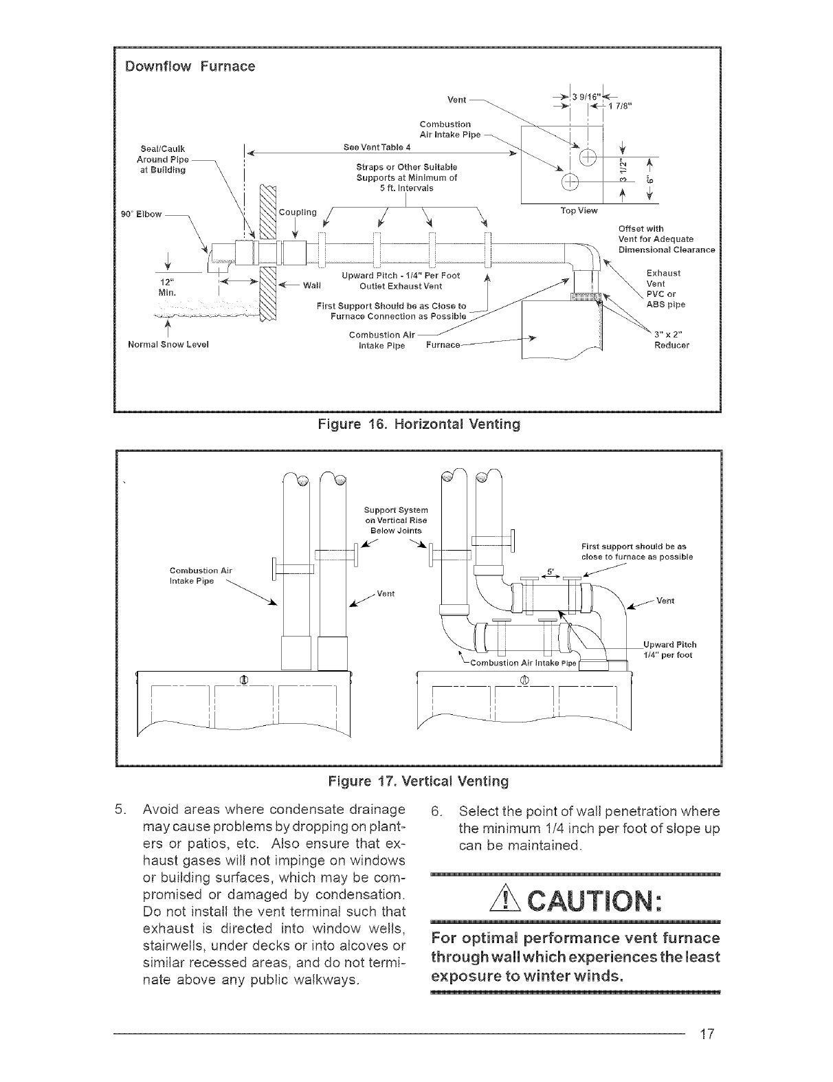
Downflow Furnace
Seal/Cat_lk I_
Around Pipe
at Building \\\\\\
90 ° Elbow _ \
\\
f
Normal Snow Level
Vent _ _!3 9/1E"_
÷i 7,8
Combustion
Al ,oto,oO,po l i i
Straps or Other Suitable _ __-_j ___Z
Supports at Minimum of
5 ft. Intervals
' Top View
iq
Combustion Air
Intake Pipe
Offset with
Vent for Adequate
Dirnensiona_ C}eara#ce
Exhaust
Vent
PVC or
ABS pipe
Figure 16. Horizontal Venting
Support System
on Vertical Rise
Below Joints
¢//_ Vent
First support should be as
close to furnace es possible
Vent
Upward Pitch
t/4" per foot
.
Figure 17. Vertical Venting
Avoid areas where condensate drainage
may cause problems by dropping on plant_
ers or patios, etc. Also ensure that ex_
haust gases will not impinge on windows
or building surfaces, which may be com_
promised or damaged by condensation.
Do not install the vent terminal such that
exhaust is directed into window wells,
stairwells, under decks or into alcoves or
similar recessed areas, and do not termi-
nate above any public walkways.
6. Select the point of wall penetration where
the minimum I/4 inch per foot of slope up
can be maintained.
CAUTmON'.
For optimal performance vent furnace
through wall which experiences the least
exposure to winter winds.
17
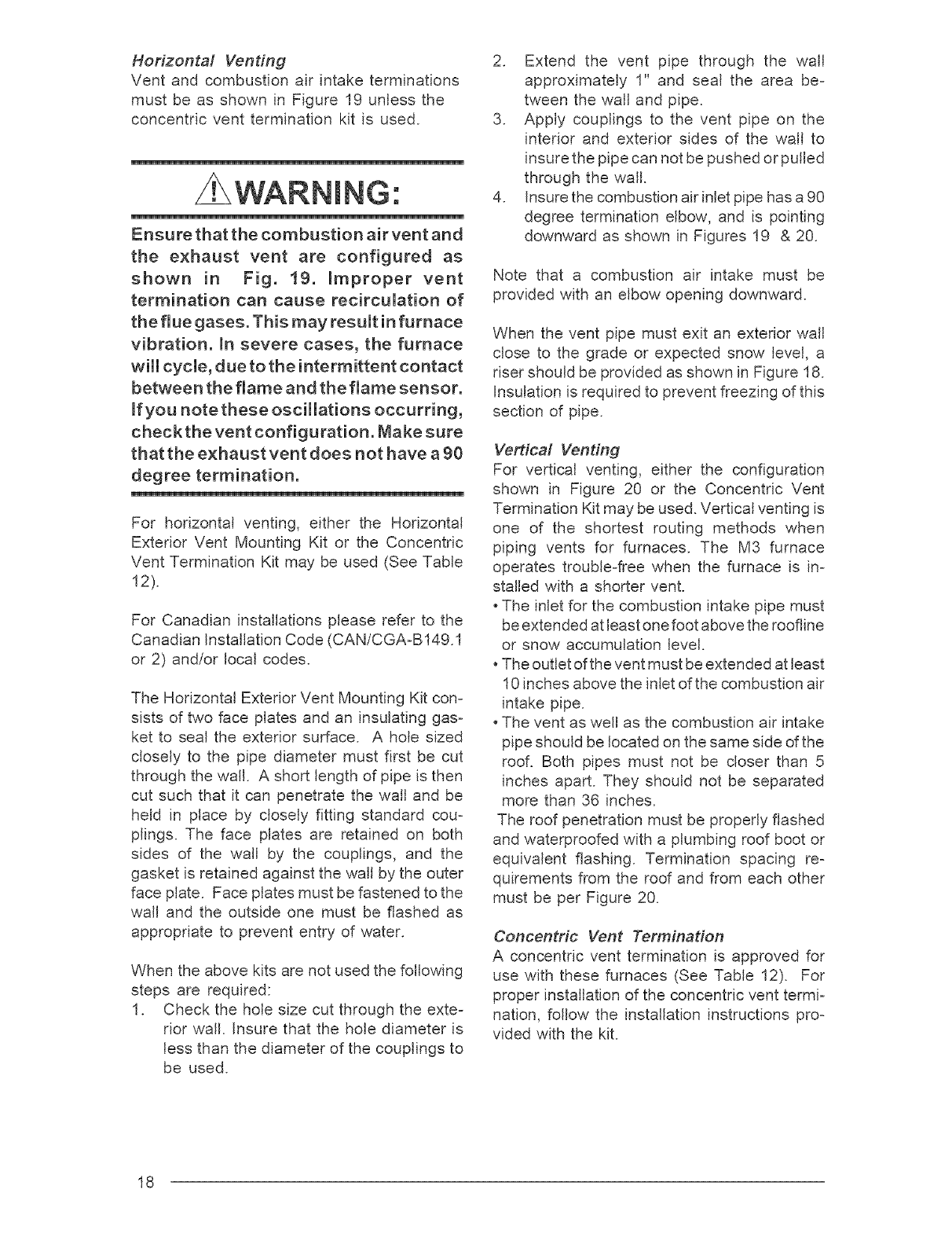
Horizontal Venting
Vent and combustion air intake terminations
must be as shown in Figure 19 unless the
concentric vent termination kit is used.
NG:
Ensure that the combustion air vent and
the exhaust vent are configured as
shown in Fig. t9. Improper vent
termination can cause recirculation of
the flue gases. This may result in furnace
vibration, in severe cases, the furnace
will cycle, due to the intermittent contact
between the flame and the flame sensor.
If you note these oscillations occurring,
check the vent configuration. Make sure
that the exhaust vent does not have a 90
degree termination.
For horizontal venting, either the Horizontal
Exterior Vent Mounting Kit or the Concentric
Vent Termination Kit may be used (See Table
12).
For Canadian installations please refer to the
Canadian Installation Code (CAN/CGA-B149.1
or 2) and/or local codes.
The HorizontaJ Exterior Vent Mounting Kit con-
sists of two face plates and an insulating gas-
ket to seal the exterior surface. A hole sized
closely to the pipe diameter must first be cut
through the wall. A short length of pipe is then
cut such that it can penetrate the wall and be
held in place by closely fitting standard cou-
plings. The face plates are retained on both
sides of the waJJ by the couplings, and the
gasket is retained against the wail by the outer
face plate. Face plates must be fastened to the
walJ and the outside one must be flashed as
appropriate to prevent entry of water.
When the above kits are not used the following
steps are required:
I. Check the hole size cut through the exte-
rior wall. Insure that the hole diameter is
less than the diameter of the couplings to
be used.
2. Extend the vent pipe through the wall
approximately I" and seal the area be-
tween the wall and pipe.
3. Apply couplings to the vent pipe on the
interior and exterior sides of the wall to
insure the pipe can not be pushed or pulled
through the wall.
4. Insure the combustion air inlet pipe has a 90
degree termination elbow, and is pointing
downward as shown in Figures 19 & 20.
Note that a combustion air intake must be
provided with an elbow opening downward.
When the vent pipe must exit an exterior wall
close to the grade or expected snow level, a
riser should be provided as shown in Figure 18.
Insulation is required to prevent freezing of this
section of pipe.
Vertical Venting
For verticaJ venting, either the configuration
shown in Figure 20 or the Concentric Vent
Termination Kit may be used. Vertical venting is
one of the shortest routing methods when
piping vents for furnaces. The M3 furnace
operates trouble-free when the furnace is in-
stalled with a shorter vent.
oThe inlet for the combustion intake pipe must
be extended at least one foot above the roofline
or snow accumulation level.
oThe outlet of the vent must be extended at least
10 inches above the inlet of the combustion air
intake pipe.
, The vent as well as the combustion air intake
pipe should be located on the same side of the
reel Both pipes must not be closer than 5
inches apart. They should not be separated
more than 36 inches.
The roof penetration must be properly flashed
and waterproofed with a plumbing roof boot or
equivalent flashing. Termination spacing re-
quirements from the roof and from each other
must be per Figure 20.
Concentric Vent Terminatien
A concentric vent termination is approved for
use with these furnaces (See Table 12). For
proper installation of the concentric vent termi-
nation, follow the installation instructions pro-
vided with the kit.
18
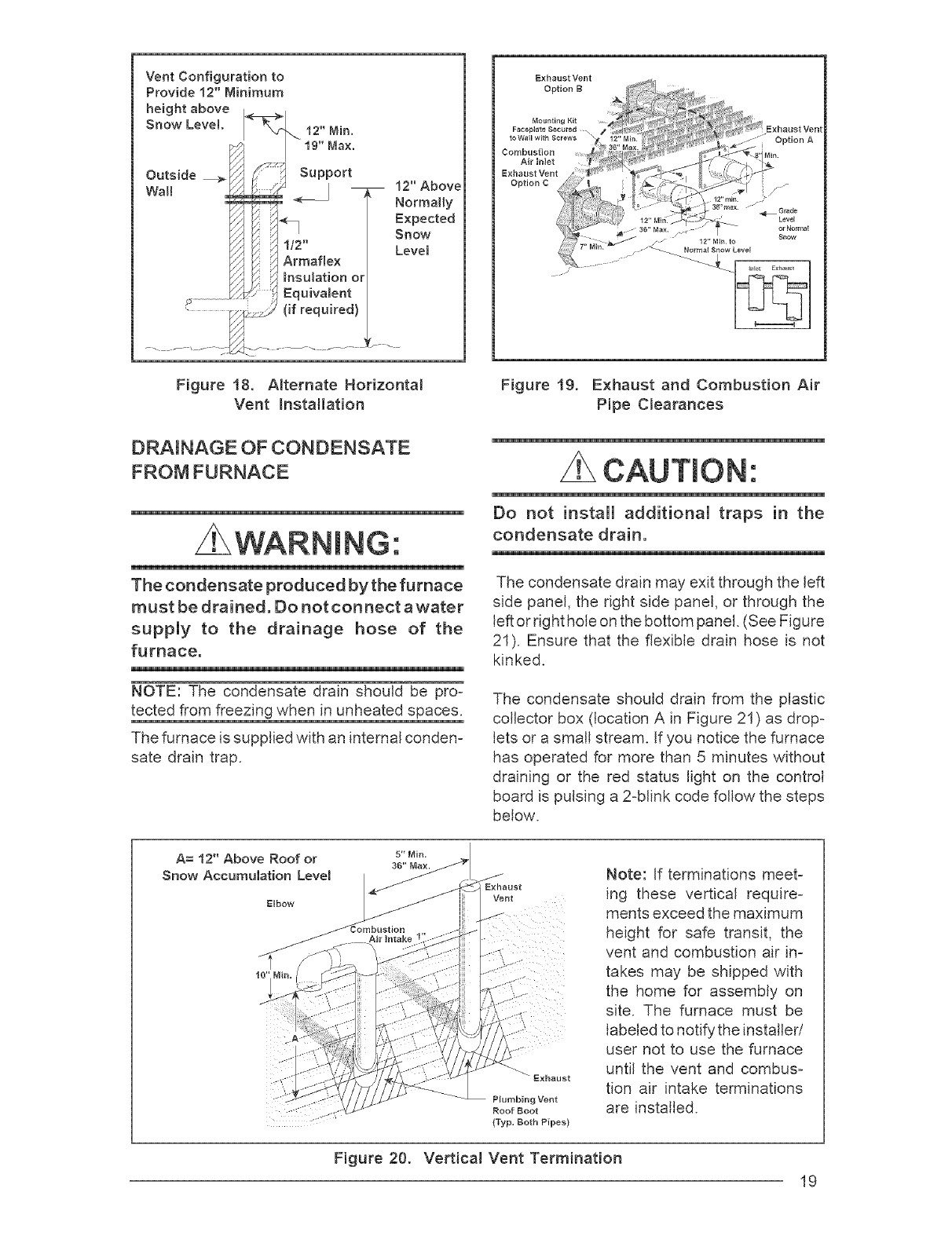
Vent Configuration to
Provide 12" Minimum
height above <7_
Snow Level. \ 12" Min.
I 19" Nax.
i
Outside _ Support
WaEI _J
i_ 1/2"
// /_ Armaflex
f/ 4
S _ Bnsulationor
,:_ Equivalent
'_..............................._ (if required)
12"Above
NormaHy
Expected
Snow
Level
Figure 18. A_ternate Horizontam
Vent Installation
DRAINAGE OF CONDENSATE
FROM FURNACE
NG:
The condensate produced by the furnace
must be drained. Do not connect awater
suppmy to the drainage hose of the
furnace.
NOTE: The condensate drain should be pro-
tected from freezing when in unheated spaces.
The furnace is supplied with an internal conden-
sate drain trap.
Exhaust Vent
Figure 19. Exhaust and Combustion Air
Pipe Clearances
CAUTION'.
Do not install additional traps in the
condensate drain.
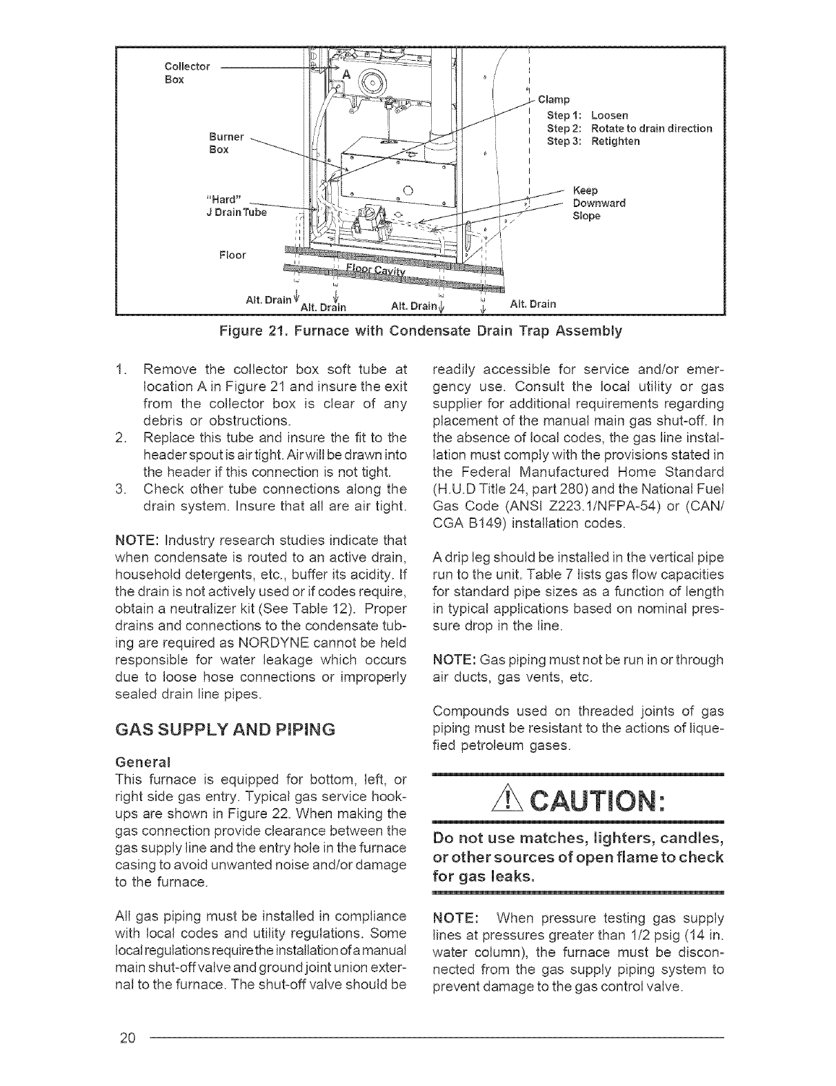
The condensate drain may exit through the left
side panel, the right side panel, or through the
left or right hole on the bottom panel. (See Figure
21). Ensure that the flexible drain hose is not
kinked.
The condensate should drain from the plastic
collector box (location A in Figure 21) as drop-
lets or a small stream. If you notice the furnace
has operated for more than 5 minutes without
draining or the red status light on the control
board is pulsing a 2-blink code follow the steps
below.
A= 12" Above Roof or s-Min.
36" l*_ax.
Snow Accumulation Level
Elbow
Bxheust
Plumbing Vent
Roof Boot
(Typ. Both Pipes)
Note: If terminations meet-
ing these vertical require-
ments exceed the maximum
height for safe transit, the
vent and combustion air in-
takes may be shipped with
the home for assembly on
site. The furnace must be
labeled to notify the installer/
user not to use the furnace
until the vent and combus-
tion air intake terminations
are installed.
Figure 20. Vertical Vent Termination
19
direction
Figure 21. Furnace with Condensate Drain Trap Assembty
I. Remove the collector box soft tube at
location A in Figure 21 and insure the exit
from the collector box is clear of any
debris or obstructions.
2. Replace this tube and insure the fit to the
header spout is air tight. Airwill be drawn into
the header if this connection is not tight.
3. Check other tube connections along the
drain system, insure that all are air tight.
NOTE: Industry research studies indicate that
when condensate is routed to an active drain,
household detergents, etc., buffer its acidity. If
the drain is not actively used or if codes require,
obtain a neutralizer kit (See Table 12). Proper
drains and connections to the condensate tub=
ing are required as NORDYNE cannot be held
responsible for water leakage which occurs
due to loose hose connections or improperly
sealed drain line pipes.
GAS SUPPLY AND PiPiNG
General
This furnace is equipped for bottom, left, or
right side gas entry. Typical gas service hook=
ups are shown in Figure 22. When making the
gas connection provide clearance between the
gas supply line and the entry hole in the furnace
casing to avoid unwanted noise and/or damage
to the furnace.
All gas piping must be installed in compliance
with local codes and utility regulations. Some
local regulations require the installation of a manual
main shut=offvalve and ground joint union exter=
hal to the furnace. The shut=off valve should be
readily accessible for service and/or emer=
gency use. Consult the local utility or gas
supplier for additional requirements regarding
placement of the manual main gas shut=off. In
the absence of local codes, the gas line instal=
lation must comply with the provisions stated in
the Federal Manufactured Home Standard
(H.U.D Title 24, part 280) and the National Fuel
Gas Code (ANSI Z223.1!NFPA=54) or (CAN/
CGA B149) installation codes.
A drip leg should be installed in the vertical pipe
run to the unit. Table 7 lists gas flow capacities
for standard pipe sizes as a function of length
in typical applications based on nominal pres=
sure drop in the line.
NOTE: Gas piping must not be run inor through
air ducts, gas vents, etc.
Compounds used on threaded joints of gas
piping must be resistant to the actions of Iique=
fled petroleum gases.
CAUTmON'.
Do not use matches, lighters, candles,
or other sources of open flame to check
for gas leaks.
NOTE: When pressure testing gas supply
lines at pressures greater than I/2 psig (14 in.
water column), the furnace must be discon-
nected from the gas supply piping system to
prevent damage to the gas control valve.
2O
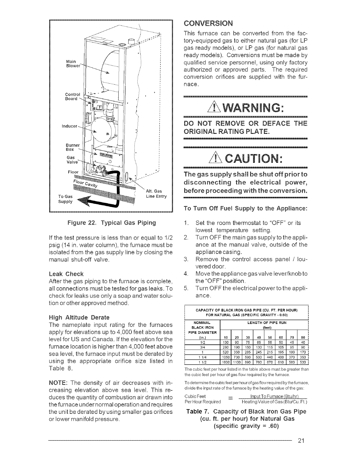
Main
Floor
To Gas
Supply
0/
/
\
/
/
J
!°
CONVERSION
This furnace can be converted from the fac=
tory=equipped gas to either natural gas (for LP
gas ready models), or LP gas (for natural gas
ready models). Conversions must be made by
qualified service personnel, using only factory
authorized or approved parts. The required
conversion orifices are supplied with the fur=
nace.
WARNING:
DO NOT REMOVE OR DEFACE THE
ORIGINAL RATING PLATE.
CAUTION'.
The gas suppmy shammbe shut off prior to
disconnecting the emectricam power,
before proceeding with the conversion.
To Turn Off Fuel Supply to the Appliance:
Figure 22. Typical Gas Piping
If the test pressure is less than or equal to I/2
psig (14 in. water column), the furnace must be
isolated from the gas supply line by closing the
manual shut=off valve.
Leak Check
After the gas piping to the furnace is complete,
all connections must be tested for gas leaks. To
check for leaks use only a soap and water solu=
tion or other approved method.
High Altitude Derate
The nameplate input rating for the furnaces
apply for elevations up to 4,000 feet above sea
level for US and Canada. If the elevation for the
furnace location is higher than 4,000 feet above
sea level, the furnace input must be derated by
using the appropriate orifice size listed in
Table 8.
NOTE: The density of air decreases with in-
creasing elevation above sea level. This re=
duces the quantity of combustion air drawn into
the furnace under normal operation and requires
the unit be derated by using smaller gas orifices
or lower manifold pressure.
I. Set the room thermostat to "OFF" or its
lowest temperature setting.
2. Turn OFF the main gas supply to the appli=
ance at the manual valve, outside of the
appliance casing.
3. Remove the control access panel /Iou=
vered door.
4. Move the appliance gasvalve lever/knob to
the "OFF" position.
5. Turn OFF the electrical power to the appli-
ance.
CAPACITY OF BLACK IRON GAS PIPE (CU. FT, PER HOUR)
FOR NATURAL GAS (SPECIFIC GRAVITY -0.60)
LENGTH OF PiPE RUN
(feet)
NOMINAL
BLACK IRON
PIPE DIAMETER
(in.) 10 20 30 40 50 60 70 80
1/2 130 90 75 65 55 50 45 40
3/4 280 190 150 130 115 105 95 90
1 520 350 285 245 215 195 180 170
1 1/4 1050 730 590 500 440 400 370 350
1 1/2 1600 1100 890 760 670 610 560 530
The cubic feet per hour listed in the table above must be greater than
the cubic feet per hour of gas flow required by the furnace
\
To determine the cubicfeet per hourofgas fie _vrequired by the furnace,
divide the input rate of the furnace by the heating value of the gas:
Cubic Feet -- hputTo Furnace_
Per Hour Required Heating Value of Gas (Btu/Cu. Ft.)
Table 7. Capacity of BJack mron Gas Pipe
(cu. ft. per hour) for Natural Gas
(specific gravity = .60)
21
To Removethe Burner Assembly:
I. Followthe instructions"To Turn Off the
FuelSupplyto theAppliance."
2. Disconnecttheflamesensorwirefromthe
burnerbox.
3. Disconnecttheignitorwiresat the 2 pin
plug.Thisis a lockingquickconnectand
bothsidesof the lowersectionmustbe
depressedin orderto be separated.
4. Removethewiresfrom the terminalsof
the gasvalve.
5. Disconnectthe rubber pressuretubes
fromthe gasvalveandthe burnerbox.
6. Removethe burneraccesscoverplate
from the burnerbox.
7. Removesupplygaspipingfromthe gas
valve.
8. Carefullyremovetheburnerassemblyfas-
tenersand removethe burnerassembly
fromtheappliance.Keepthefastenersthat
wereremoved.Notethattheburnerboxmay
havehooksnearthetopandontherightand
lefthandsides.Toremovethistypeofburner
box,lift theburnerboxupwardsandthen
removetheboxfromtheunit.
To Removethe Burner Orifices:
I. Removethefour(4)fastenersthatsecure
the gas manifoldto the burnerbox, as
showninFigure25. Carefullyremovethe
gas manifoldassemblyfrom the burner
box. Notethatthegasmanifoldassembly
consistsofthegasvalve,thegasmanifold,
andtheorifices.
2. Carefullyremovetheburnerorificesfromthe
gasmanifold,asshowninFigure25.
CAUTmON'.
Caution: Do not re-drill the burner
orifices. If the orifice size must be
changed, use only new orifices.
Note: The size of the new orifices that will be
installed into the unit will depend upon the
type of conversion (sea level or Hgh altitude;
natural gas or LP gas}.
To Convert the Unit to the Alternate Gas
I. Remove the orifice bag from the manifold
of the unit.
2. Install the appropriate gas burner orifices
into the gas manifold. Remember if in-
stalling at altitudes above 4,000 feet to
install the proper orifices, shown in Table
8. When installing the new orifices, DO
NOT use pipe joint compound on the
orifice threads. Screw the orifices into the
manifold by hand until snug to eliminate
cross threading, then tighten with a
wrench. Before installing an orifice, check
the face or side of the orifice for the drill
number to ensure that it is the appropriate
size.
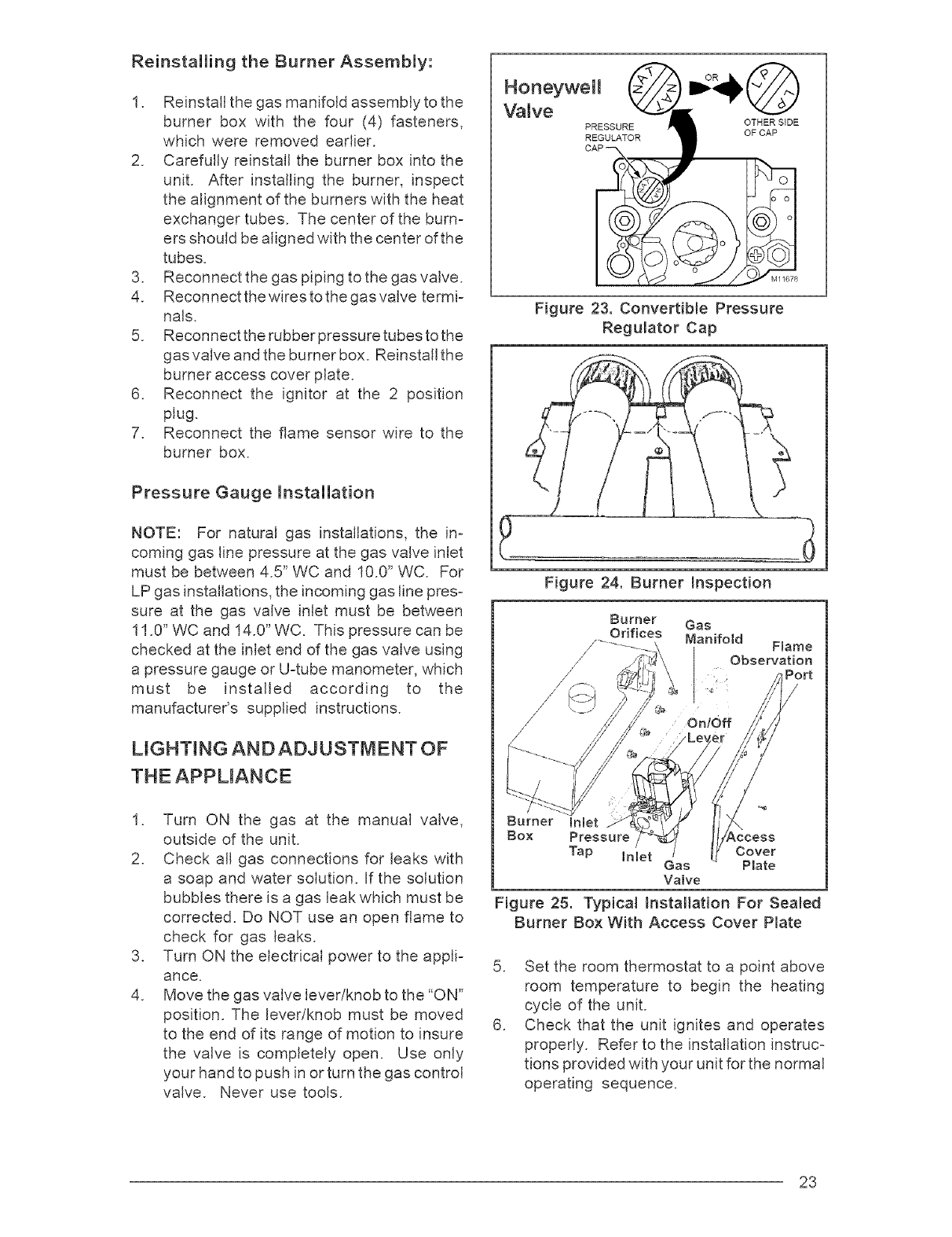
3. For the conversion to the alternate fuel,
the gas valve regulator cap must be turned
over, as shown in Figure 23. You will
unscrew the cap and reinstall for your in=
stallation. After reinstalling the cap, you will
be able to read "NAT" for the conversion to
natural gas or"LP for the conversion to LP
gas.
Furnace
Model Number
M3RL -
Furnace Rating Elevation
Plate Input No. of 0- 2000
(Btuh) Burners
Elevation
4000-6000
Elevation
2000-4000
Nat LP
50 57
49 1.15 mm
Elevation
6000-8000
Elevation
8000-10000
Nat LP Nat LP Nat LP Nat LP
060A-A/BW 60,000 4 50 57 51 58 51 58 52 59
080A-A/BW 80,000 5 49 1.15 mm 50 57 50 57 51 58
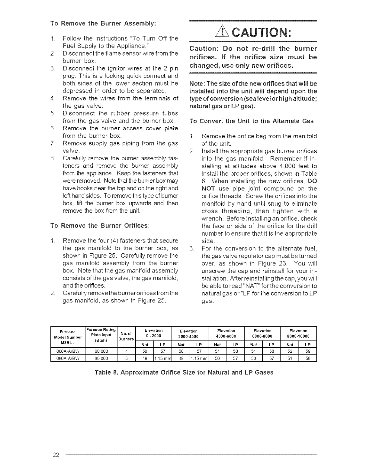
Table 8. Approximate Orifice Size for Natural and LP Gases
22
Reinstalling the Burner Assembly:
I. Reinstal[ the gas manifold assembly to the
burner box with the four (4) fasteners,
which were removed earlier.
2. Carefully reinstall the burner box into the
unit. After installing the burner, inspect
the alignment of the burners with the heat
exchanger tubes. The center of the burn-
ers should be aligned with the center of the
tubes.
3. Reconnect the gas piping to the gas valve.
4. Reconnectthewirestothegasvalve termi-
nals.
5. Reconnect the rubber pressure tubes to the
gas valve and the burner box. Reinstall the
burner access cover plate.
6. Reconnect the ignitor at the 2 position
plug.
7. Reconnect the flame sensor wire to the
burner box.
Pressure Gauge installation
NOTE: For natural gas installations, the in-
coming gas line pressure at the gas valve inlet
must be between 4.5" WC and 10.0" WC. For
LP gas installations, the incoming gas line pres-
sure at the gas valve inlet must be between
11.0" WC and 14.0" WC. This pressure can be
checked at the inlet end of the gas valve using
a pressure gauge or U-tube manometer, which
must be installed according to the
manufacturer's supplied instructions.
LiGHTiNG AND ADJUSTMENT OF
THE APPLIANCE
I. Turn ON the gas at the manual valve,
outside of the unit.
2. Check all gas connections for leaks with
a soap and water solution. If the solution
bubbles there is a gas leak which must be
corrected. Do NOT use an open flame to
check for gas leaks.
3. Turn ON the electrical power to the appD
ance.
4. Move the gas valve lever/knob to the "ON"
position. The lever/knob must be moved
to the end of its range of motion to insure
the valve is completely open. Use only
your hand to push in or turn the gas control
valve. Never use tools.
Hoooywo,
Valve
PRESSURE OTHER SIDE
OF CAP
REGULATOR
Figure 23. Convertible Pressure
Regulator Cap
Figure 24. Burner Inspection
Burner inlet
Box Pressure Cover
Tap inlet Gas Plate
Valve
Figure 25. Typical Installation For Sealed
Burner Box With Access Cover Plate
5. Set the room thermostat to a point above
room temperature to begin the heating
cycle of the unit.
6. Check that the unit ignites and operates
properly. Refer to the installation instruc-
tions provided with your unit for the normal
operating sequence.
23
7. Aftertheflameignites,visuallyinspectthe
burnerassemblyto ensurethattheflame
isdrawndirectlyintothecenteroftheheat
exchangertube,as shownin Figure23.
Theend of theflamewill beout of sight
aroundthe bendof the heatexchanger
tube.Inaproperlyadjustedburnerassem-
bly,the flamecolor shouldbe bluewith
somelightyellowstreaksnearthe outer
portionsoftheflame.
CAUTmON'.
To avoid electric shock, personal
injury, or death, turn off the power at
the disconnect or the main service
panel before making any electrical
connections.
NOTE: Until all of the air is bled out of the gas
line, the hot surface ignitor may not ignite the gas.
Ifthe ignition control locks out, turn the thermostat
to its lowest setting and wait one minute then turn
the thermostat to a point above room temperature
and the ignitor will try again to ignite the main
burners. This process may have to be repeated
several times before the burners will ignite. Once
the burners are lit, check all gas connections for
leaks again with the soap and water solution. If
the solution bubbles there is a gas leak which
must be corrected. Do not use an open flame to
check for gas leaks.
Manifold Pressure
The gas valve for the M3 furnace series is
equipped with a special conversion pres-
sure regulator cap. The pressure regulator
cap is factory set. If the gas valve is con-
verted from natural gas to propane gas or
vise versa, the manifold pressure of the gas
valve will be set to pressure listed in Table 9.
Type of Fuel Manifold Pressure
In.WC
Natural Gas: 3.5
Propane (LP) Gas: 10.0
Table 9. Manifold Pressure
COMPLETING THE CONVERSION
I. Affix the gas valve conversion label found
in the package with the orifices to the unit
rating plate.
2. Run the appliance through a complete
cycle to assure proper operation.
ELECTRICAL WIRING
Genera!
Electrical connections must be made in accoF
dance with all applicable local codes and ordi-
nances, and with the current revision of the
National Electric Code (ANSI/NFPA 70).
For Canadian installations electrical connec-
tions and grounding must be done in accoF
dance with the current Canadian Electrical
Code (CSA C22.1 Part 1) and/or local codes. If
any of the original wire as supplied with the
furnace must be replaced, it must be replaced
with wire having a minimum temperature rating
of I05°C. Refer to the furnace nameplate and
Table 8 for electrical requirements.
Line Voltage Wiring
The line voltage (115 volt) to the furnace must
be supplied from a dedicated branch circuit
containing the correct fuse or circuit breaker
for the furnace. See Table 10. An electrical
switch should be readily accessible from and
within sight of the furnace. See the Wiring
Diagram label in the furnace for more details.
The furnace cabinet must have an uninteF
rupted, unbroken ground to minimize injury
should an electrical fault condition occur. The
controls used in this furnace require an earth
ground to operate properly. Acceptable meth-
ods for grounding are electrical wire or conduit
approved for electrical ground service. Do not
use gas piping as an electrical ground.
NOTE: Proper line voltage polarity must be
maintained in order for the control system to
operate correctly. Verify that the incoming neu-
24
trallineis connectedto thewhitewireandthe
incoming"hot"lineis connectedto the black
wireinthefurnacejunctionbox.Thefurnacewill
not operateunlesspolarityand groundare
properlyconnected.SeeFigure26.
Label all wires prior to disconnection
when servicing controls. Wiring errors
can cause improper and dangerous
operation.
Verify proper operation after servicing.
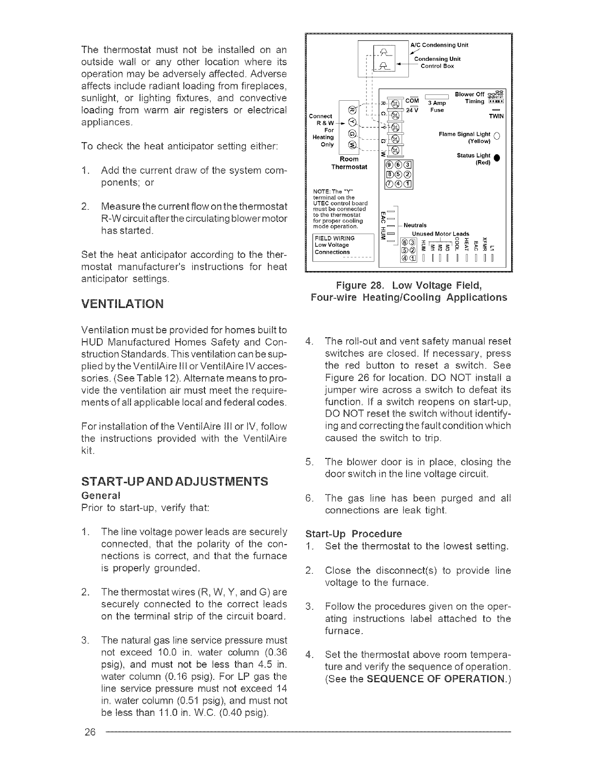
Low Voltage Wiring
install the thermostat per the manufacturer's
instructions. The low voltage (24 volt) connec=
tions from the thermostat are made at the
terminal strip on the control board in the furnace.
See Figure 28 for the proper connections for
heating only (two=wire) and heating/cooling
(four=wire) applications. The recommended
minimum wire gauge for thermostat wiring is
shown in Table 10.
Lors des operations d'entretien des
commandes, _tiqueter tousles files
avant des les d_connecter. Toute erreur
de c_blage peut _tre une source de
danger et de panne.
S'assurer du bon fonctionnement de
l'appareil apr_s tout entretien.
c::_::_ C=_] _ BowerOff
Til/mg
24 V
©TWIN
_1®1
o1®1
_1®=_
Figure 27. Blower Speed Tap Location
Furnace Cabinet Nominal Maximum Minimum Maximum Minimum Maximum
Input Width Electrical Operating Operating Furnace Wire Fuse or Circuit
(Btuh) (in.) Supply Voltage Voltage Amperes Gauge Breaker Amps*
60,000 19.75 115-60-1 127 103 9.7 14 15
80,000 19.75 115-60-1 127 103 9.7 14 15
Thermostat Wire Gauge Recommended Thermostat Wire Length
2-wire (heating) L4or 5-wire (cooling)
55 ft. 25 ft.
90 ft. 45 ft.
140 ft. 70 ft.
225 ft. 1t0 ft.
24
22
20
18
* Time-delay fuses or HACR-type circuit breakers are required,
Table 10. Electricam Data
F_/IS ;PerPvliiedepaFnieel'd Snupp/iteodr
Panel _
WhltB2aNk_tH_rOtl)_ Black _Black _ _-] Black
Green_orB_a_rE_...... _....... _ .... _ ....... ._Ll_',' I
(Ground) _ _ _ I I =
Ground /Ground
Field Supplied Disconnect
Within Sight of Furnace
..... Field Line Voltage
Wiring
__ Factory Line
Voltage Wiring
Ground
Junction Box (may be internal
or external to the furnace). These
connections can be made in the
field supplied disconnect at the
furnace.
Figure 26. Line Voltage Field Wiring 25
The thermostatmust not be installedon an
outsidewaft or any other locationwhereits
operationmaybeadverselyaffected.Adverse
affectsincluderadiantloadingfromfireplaces,
sunlight,or lightingfixtures,and convective
loadingfrom warmair registersor electrical
appliances.
To checktheheatanticipatorsettingeither:
I. Addthe currentdrawof thesystemcom-
ponents;or
2. Measurethecurrentflowonthethermostat
R-Wcircuitafterthecirculatingblowermotor
hasstarted.
Settheheatanticipatoraccordingto thether-
mostat manufacturer'sinstructionsfor heat
anticipatorsettings.
VENTiLATiON
C°"dens'°gun't
!- Condensing Unit
F i
E i
Connect '
R&W
For
Heating
Only
Room
Thermostat
NOTB:The "'Y"
terminal on the
UTEC control board
must be connected
to the thermostat
for proper cooling
mode operation.
oo
E::::_::_ C_=M _Blower Off e_
3 Amp Timing
24=V Fuse
OTWIN
F,ameBignalLight0
(Yellow)
_::= Status Light 0
(Red)
I _ Neutrals
C _ Unused Motor Leads
u: o m
DD_DDD_
Figure 28. Low Voltage Field,
Four=wire Heating/Cooling Applications
Ventilation must be provided for homes built to
HUD Manufactured Homes Safety and Con=
struction Standards. This ventilation can be sup=
plied by the VentiiAire Ill or VentilAire iV acces-
sories. (See Table 12). Alternate means to pro=
vide the ventilation air must meet the require-
ments of all applicable local and federal codes.
For installation of the VentiiAire Ill or IV, follow
the instructions provided with the VentilAire
kit.
START-UP AND ADJUSTMENTS
General
Prior to start=up, verify that:
I. The line voltage power leads are securely
connected, that the polarity of the con=
nections is correct, and that the furnace
is properly grounded.
2. The thermostat wires (R, W, Y, and G) are
securely connected to the correct leads
on the terminal strip of the circuit board.
.The natural gas line service pressure must
not exceed 10.0 in. water column (0.36
psig), and must not be less than 4.5 in.
water column (0.16 psig). For LP gas the
line service pressure must not exceed 14
in. water column (0.51 psig), and must not
be less than 11.0 in. W.C. (0.40 psig).
26
.The roll-out and vent safety manual reset
switches are closed. If necessary, press
the red button to reset a switch. See
Figure 26 for location. DO NOT install a
jumper wire across a switch to defeat its
function. If a switch reopens on start-up,
DO NOT reset the switch without identify-
ing and correcting the fault condition which
caused the switch to trip.
5. The blower door is in place, closing the
door switch in the line voltage circuit.
6. The gas line has been purged and all
connections are leak tight.
Start-Up Procedure
I. Set the thermostat to the lowest setting.
2. Close the disconnect(s) to provide line
voltage to the furnace.
3. Follow the procedures given on the oper-
ating instructions label attached to the
furnace.
4. Set the thermostat above room tempera-
ture and verify the sequence of operation.
(See the SEQUENCE OF OPERATION.)
.After the furnace has run for approximately
five minutes, set the thermostat below room
temperature and verify steps 9 - 11 of the
SEQUENCE OF OPERATION.
Shut Down Procedure
in the event that the furnace must be shut down,
follow this procedure:
I. Set the room thermostat to "OFF" or its
lowest temperature setting.
2. Turn OFF the main gas supply to the appli-
ance at the manual valve outside of the
appliance casing.
3. Remove the control access panel /Iou-
vered door.
.
5.
Move the appliance gas valve lever/knob
to the "OFF" position.
Turn OFF the electrical power to the
appliance.
Verifying Firing Rate
The firing rate must be verified for each instal-
lation to prevent over-firing the furnace.
NOTE: The firing rate must not exceed the
rate shown on the furnace rating plate. At
altitudes above 4000 ft. it must not exceed
that on the rating plate mess 4% for each
1000 ft.
Use the following procedure to determine the
firing rate:
I. Shut off all other gas fired appliances.
2. Start the furnace and allow it to run for at
least three minutes.
.
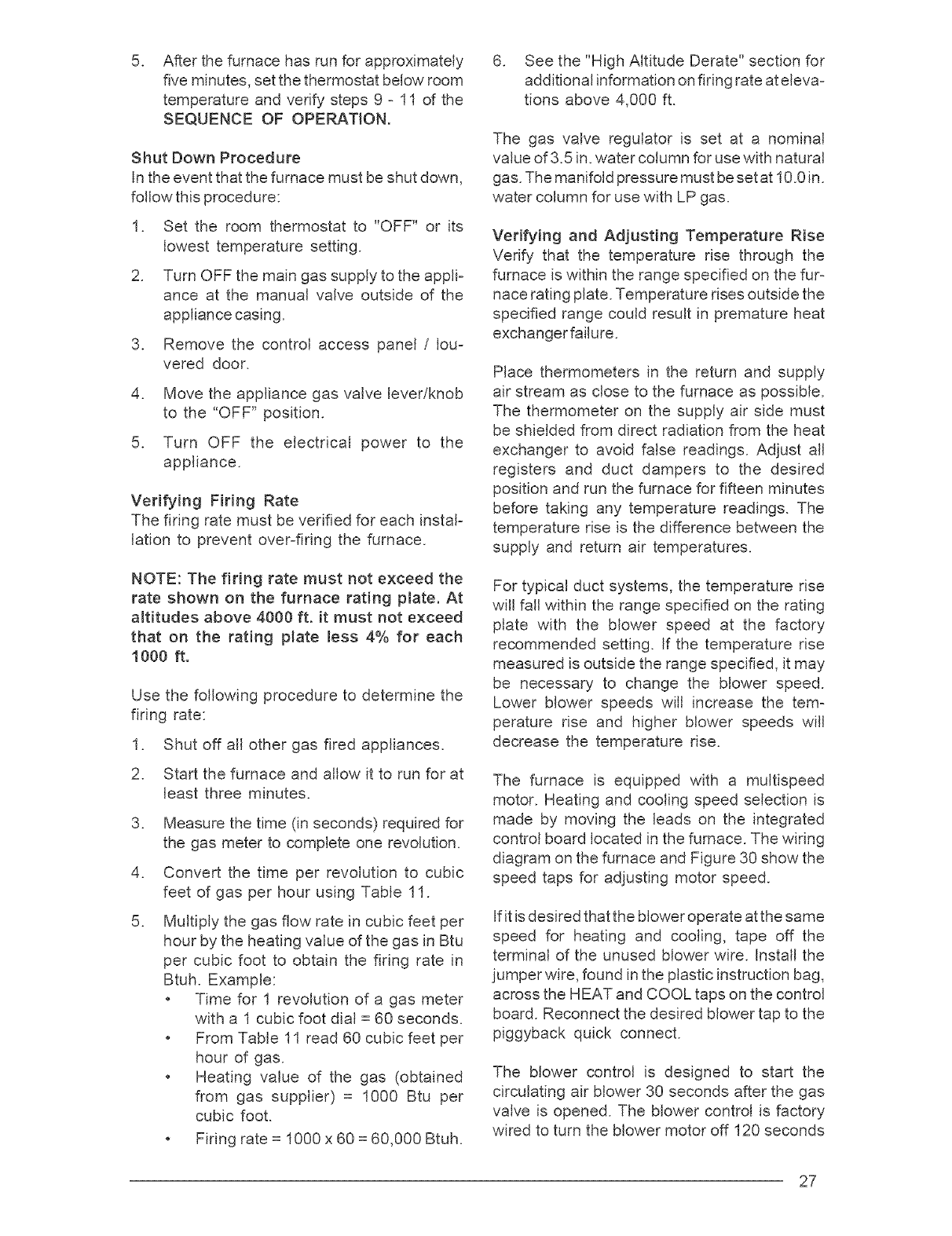
4.
5.
Measure the time (in seconds) required for
the gas meter to complete one revolution.
Convert the time per revolution to cubic
feet of gas per hour using Table 11.
Multiply the gas flow rate in cubic feet per
hour by the heating value of the gas in Btu
per cubic foot to obtain the firing rate in
Btuh. Example:
o Time for I revolution of a gas meter
with a I cubic foot dial = 60 seconds.
o From Table 11 read 60 cubic feet per
hour of gas.
o Heating value of the gas (obtained
from gas supplier) = 1000 Btu per
cubic foot.
, Fidng rate = I000 x 60 = 60,000 Btuh.
6. See the "High Altitude Derate" section for
additional information on firing rate at eleva-
tions above 4,000 ft.
The gas valve regulator is set at a nominal
value of 3.5 in. water column for use with natural
gas. The manifold pressure must be set at I 0.0 in.
water column for use with LP gas.
Verifying and Adjusting Temperature Rise
Verify that the temperature rise through the
furnace is within the range specified on the fur-
nace rating plate. Temperature rises outside the
specified range could result in premature heat
exchanger failure.
Place thermometers in the return and supply
air stream as close to the furnace as possible.
The thermometer on the supply air side must
be shielded from direct radiation from the heat
exchanger to avoid false readings. Adjust all
registers and duct dampers to the desired
position and run the furnace for fifteen minutes
before taking any temperature readings. The
temperature rise is the difference between the
supply and return air temperatures.
For typical duct systems, the temperature rise
will fall within the range specified on the rating
plate with the blower speed at the factory
recommended setting. If the temperature rise
measured is outside the range specified, it may
be necessary to change the blower speed.
Lower blower speeds will increase the tem-
perature rise and higher blower speeds will
decrease the temperature rise.
The furnace is equipped with a multispeed
motor. Heating and cooling speed selection is
made by moving the leads on the integrated
control board located in the furnace. The wiring
diagram on the furnace and Figure 30 show the
speed taps for adjusting motor speed.
If it is desired that the blower operate at the same
speed for heating and cooling, tape off the
terminal of the unused blower wire. Install the
jumper wire, found in the plastic instruction bag,
across the HEAT and COOL taps on the control
board. Reconnect the desired blower tap to the
piggyback quick connect.
The blower control is designed to start the
circulating air blower 30 seconds after the gas
valve is opened. The blower control is factory
wired to turn the blower motor off 120 seconds
27
TIME FOR
ONE REVOLUTION
(SECONDSI
24
26
28
3O
32
34
36
38
4O
42
44
46
48
5O
52
54
56
58
6O
62
64
1
150
138
129
120
113
106
100
95
90
GAS FLOW RATE (CUBIC FEET PER HOUR)
CUBIC FEET PER REVOLUTION OF TIME FOR
ONE REVOLUTION
J(sEcONDs)
8O
82
84
86
88
9O
92
94
96
98
100
102
104
106
108
110
112
114
116
118
120
METER
5 10
750 1500
692 1385
643 1286
600 1200
563 1125
529 1059
500 1000
474 947
450 900
86 429 857
82 409 818
78 391 783
75 375 750
72 360 720
69 346 692
67 333 667
64 321 643
62 310 621
60 300 600
58 290 581
56 281 563
CUBIC FEET PER REVOLUTION OF
METER
1
45
44
43
42
41
40
39
38
38
37
36
35
35
34
33
33
32
32
31
31
3O
5 10
225 450
220 439
214 429
209 419
205 409
200 400
196 391
191 383
188 375
184 367
180 360
176 353
173 346
170 340
167 333
164 327
161 321
158 316
155 310
153 305
150 300
Table 11. Gas Flow Rate
after the gas valve is dosed. This timing can be
changed using the BLOWER OFF timing switch
opposite the terminal block on the control board
(See Figure 27).
Verifying Burner Operation
To verify operation of the burners, remove front
door and ensure that the door switch is in the "on"
position (see Figure 29). Set the thermostat above
room temperature and observe the ignition se-
quence. The flame can be observed through the
small clearwindow on the burner box. The burner
flame should carry over between all burners. The
flames should be blue, without yellow tips. Flames
should extend from each burner without lifting,
curling, or floating. After verifying ignition, set the
thermostat below room temperature and verify
that the burner flame extinguishes completely.
Replace the front door.
Verifying Operation of the Supply Air
Limit Switch
To verify operation of the supply air limit switch,
make sure that the blower door is in place and
that there is power to the furnace. Completely
block the return airflow to the furnace by install=
ing a close=off plate in place of or upstream of
the filter(s). Set the thermostat above room
temperature and verify that the Sequence of
Operation is as described in these instructions.
The supply air limit switch should function to
turn off the gas valve within approximately five
minutes. The circulating air and combustion
blowers should continue to run when the supply
air limit switch opens. Remove the close=off
plate immediately after the supply air limit switch
opens. If the furnace operates for more than five
minutes with no return air, set the thermostat
below room temperature, shut off the power to
the furnace, and replace the supply air limit
switch.
DESCRiPTiON OF COMPONENTS
Figure 29 shows the location of each of the
functional components described below. If any
component of the furnace must be replaced,
use only factory authorized replacement parts.
Contact your distributor for the approved re=
placement parts.
Flame Sensor - The flame sensor acts to
prove that flame has carried over from the
ignitor to the opposite end burner. If no flame is
sensed, the furnace will be shut down automati=
cally.
28
FURNACE ACCESSORY KtTS MAINTENANCE
Kit
A/C Coil Box
Side Return Air Kit
Top Return Air Kit
Sloped Roof VentilAire Ill Kit
Sloped Roof VentilAire IV Kit
Soffit VentilAire Kit
Concentric Vent Termination Kit
(for horizontal and vertical ventin,q)
Horizontal Exterior Vent
Mounting Kit 3"PVC
Neutralizer Kit - All Models
Order Number
911969A
904003
904015
914098
914229
917201
903578
902375
902377
Table 12. Accessory Kits
Gas Vamve - The gas valve controls the flow of
gas to the burners. When the gas valve is
energized it automatically opens and regulates
the gas pressure in the manifold.
Pressure Switch - The pressure switch veal-
ties that the inducer is drawing the combustion
gases through the heat exchanger. It alsosenses
a blocked condensate drain condition.
Deck Limit Switch (Auxiliary Limit) - The
deck limit protects the furnace filter tempera-
ture from overheating when the motor has
malfunctioned. If the deck switch opens, the
power for the furnace will shut down (see
Figure 29).
Supply Air Limit Switch - The supply air limit
switch prevents the air temperature leaving the
furnace from exceeding the maximum outlet air
temperature.
Vent Safety Switch - The vent safety switch
shuts the furnace down if the outlet flue gas
temperature increases above 145°F. This
switch protects the plastic flue system and the
inducer from over-temperature conditions.
Flame Roll-Out Switch - This switch pro-
vides flame roll-out protection to the furnace
and combustion air inlet pipe.
It is recommended that the furnace be checked
yearly. At a minimum, this check should include
the following items:
WARNmNG'.
To avoid electric shock, personal injury,
or death, turn off the power at the
disconnect or the main service panel
before performing any maintenance.
WARNING:
Holes in the vent pipe or heat exchanger
can cause products of combustion to
enter the occupied space. Replace the
vent pipe or heat exchanger if leaks are
found. Failure to prevent products of
combustion from being circulated into
the occupied space can crate poten-
tially hazardous conditions, including
carbon monoxide poisoning, that could
result in personal injury or death.
Combustion Air and Vent System
Check the combustion air and vent pipe to
ensure that it is not damaged, corroded or
blocked by debris. Any damaged section of
vent pipe must be replaced, and any obstruc-
tion or blockage must be removed prior to
operating the furnace.
Air Filter
An air filter is supplied with the furnace as
shipped from the factory. Filters should be
changed or cleaned monthly during the heating
season. New or newly renovated homes may
require more frequent changing until the con-
struction dust has been removed.
29
Never operate the furnace without a
filter Jn pmace. Dust and mintJn the return
air can buJmd up on Jntemam compo-
nents, resumtJng Jn moss of efficiency,
equipment damage, and possJbme fire.
Lubrication
The bearings in the circulating air blower mo-
tors are prequbdcated and sealed at the fac-
tory. No further oiling of the bearings is required
for the life of the motor.
Condensate Drain AssemMy
Be sure the condensate lines are free and open
(i.e. avoid kinking hoses). Also make sure all
hose clamps are tight to avoid drawing air into
the system.
Blower Compartment
The blower compartment should be cleaned
monthly during the heating and cooling sea-
sons to remove any dirt and lint that may have
accumulated in the compartment or on the
blower and motor. Dirt and lint can create
excessive loads on the motor resulting in higher
than normal operating temperatures and short-
ened service life.
Heat Exchanger and Burner Maintenance
The furnace should operate for many years
without excessive soot buildup in the flue pas-
sageways, however, the flue passageways,
the vent system, and the burners should be
inspected and cleaned (if required) by a quali-
fied service technician annually to ensure con-
tinued safe operation. Particular attention must
be given to identify deterioration from corrosion
or other sources.
SYSTEM OPERATION
iNFORMATiON
GENERAL
Proper maintenance is most important to
achieve the best performance from a
furnace. Follow these instructions for years
of safe, trouble free operation.
o Do not place combustible materials on or
against the furnace cabinet or the vent pipe.
3O
Do not store gasoline or any other
flammable vapors and liquids in the vicinity
of the furnace.
Change or replace the air filters monthly
during any period when the circulating
blower is operating regularly.
Always replace the doors on the furnace
after servicing. Do not operate the furnace
without all doors and covers in place.
Avoid operating the furnace when windows
and doors are open.
Be sure that the thermostat is propermy
installed and is not being affected by
drafts or heat from mamps or other
appliances.
Sequence of Operation
Operating sequences for the heating, cooling,
and fan modes are described below. Refer to
the wiring diagrams (Figures 30) and the low
voltage field wiring diagram (Figure 26) for
more details.
Heating Mode:
I. On a call for heat the thermostat closes,
applying 24 VAC to the W terminal on the
control board.
2. The control board checks for continuity
on the 24 VAC limit control circuit (over-
temperature limit switch, flame rollout
switches and blocked vent switch in se-
ries). If an open limit is detected the con-
trol board will energize the inducer and
the conditioned air blower. All other sys-
tem functions win be inoperable until the
limit circuit closes. While the limit is open,
the red LED will pulse at a rate of I blink
per unit time.
3. The furnace control checks for continuity
across the pressure switch (24 VAC). If
the pressure switch is closed the heat
mode sequence will not continue. If it
remains closed for 10 seconds the red
LED will blink 3 times repetitively until the
fault condition clears.
4. The inducer is energized.
5. The pressure switch win close. If the
pressure switch does not close after 10
seconds the fault LED will blink 2 times
repetitively and the inducer will continue
to run until the switch is closed.
6. The inducer will pre-purge for 30 seconds
and then the igniter will start its warm-up
as follows:
InitialPowerup:After30secondsofigniter
warm-upthegasvalve(24VAC)willthen
open. The ignitercircuitwill stay ener-
gizedfor 3 secondsafter the gasvalve
opens.
AfterInitialPowerup: Thecontrolhasa
programmedadaptiveignition feature
whichvariesthe warm-upperiodas fol-
lows:Ifignitionissuccessfulthewarm-upis
reducedby3-secondsoneachsubsequent
call for heatuntil ignitionfailureoccurs.
Uponignitionfailure,the warm-upis in-
creasedby 3-secondson the nexttry. If
successful,thetimingremainsfixedatthis
level.Ingeneral,wheneverignitionfailure
occursthewarm-upintervalisincreasedby
3-secondsonthenexttry.Andifsuccess-
ful, it remainsthere.Minimumandmaxi-
mumwarm-uptimelimitsareset at6and
54-seconds,respectively.
7. Thefurnacecontrolmustproveflamevia
theflamesensor5 secondsafterthegas
valveopens.Ifflameis sensed,all burn-
ers areon andtheignitorcoolsoff. If no
flame is sensed,the gas valve closes
immediatelyandtheinducercontinuesto
run. A secondtrial for ignition(step6)
beginsif noflameis sensed.Onthefifth
tryforignition,thefurnacecontrolislocked
out and the red LEDwill blink4 times
repetitively. The thermostat must be
openedfor at leastten secondsto reset
the furnacecontrolaftera lockout. Oth-
erwise,the furnacewill attemptanother
ignitionsequencein 1hour.
8. The furnace control energizesthe cir-
culatingair blowerontheheatingspeed
30secondsafterthe gasvalvecircuitis
energized.
9. When the thermostat has been satisfied,
gas valve is de-energized.
10. The inducer is de-energized after a 30-
second postpurge.
11. The furnace control keeps the circulating
air blower energized for 120 seconds
(factory set) or 60, 90, or 180 seconds
(field adjustable). (See Figure 27.)
12. Abnormal conditions: If a limit opens during
operation, the inducer and circulating air
blower continue to operate. The gas valve
is de-energized immediately. The blowers
continue to operate until the limit closes.
When the limit closes the inducer blower is
de-energized immediately. The circulating
air blower continues to operate for the speci-
fied delay (factory set at 120 seconds).
Cooling Mode:
I. On a call for cooling the thermostat closes,
applying 24 VAC to the G and Y terminals
on the furnace control. This closes the
compressor contactor.
2. The furnace control energizes the circu-
lating blower (115 VAC) on the cooling
speed.
3. When the thermostat is satisfied, the G
and Y terminals on the control board are
de-energized opening the compressor
contactor.
4. The circulating air blower is de-energized
after a 90-second delay.
Fan Mode:
I. On a callforfan
.
3.
operation, the thermostat
applies 24 VAC to the G terminal on the
furnace control board.
The circulating air blower is energized
immediately on the heating speed.
If the furnace is operated in the continu-
ous ON position at the thermostat and is
then switched to AUTO, the circulating
blower will operate for a specified delay
(factory set at 120 seconds).
Furnace Fails to Operate
If the furnace does not operate check the
following:
I. Is the thermostat operating properly?
2. Is the front door in place?
3. Is the furnace disconnect closed?
4. Has the circuit breaker tripped or the
control board fuse burned open?
5. Is the gas turned on?
6. Are any manual reset switches open?
7. Is the filter dirty or plugged?
8. Is the flame sensor coated? (Remove
and clean with emery cloth.)
9. Is the deck switch open?
If the furnace locks out after 5 attempts for
ignition, it will try again every hour if a call for
heat remains. If the inducer and circulating air
blowers are operating, and items I through 8
have been checked, press the red reset but-
ton on the vent safety switch. (See Figure 29.)
If the furnace operates after depressing the
reset button, contact a qualified service tech-
nician to identify and repair the problem.
If furnace still fails to operate, depress the red
reset buttons on the flame roll-out switch. If
the furnace operates after depressing the
reset button, contact a qualified service tech-
nician to identify and repair the problem.
31
M3 Dewnflow Furnace
1 Door Assembly -Louvered
Filter Inside Door
3 Blower Assembly
4 Control Board
5 Pressure Switch
6 Flame Rollout Switch
"J" Trap Hard Tube
8 LowVoltage Transformer
9 In Line Drain Assembly
10 Junction Box
11 Vent Safety Switch
12 Ignitor Assembly
13 BurnerView Port
14 Main Limit Switch
15 Coil Cabinet Assembly (Optional)
16 Flame Sensor (On Burner Box)
17 Gas Valve
18 Switch, On/Off
19 Blower, Inducer
20 Orifice(In BurnerBox)
21 Aux. Limit
BurnerBox
Figure 29. Location of Major Components
32
FAULT CONDmON
Power On
Limit Circuit Open or External Load On "W"
(Does not apply to Deck Switch, see below)
Pressure Switch Open with Inducer On
Pressure Switch Closed with Inducer On
!gn!t!on Fai!ure (Check Ground)
115 VAC & Neutral Reversed or no Ground
False Flame or Gas Valve Relay Shorted
Power Off or Deck Limit Open
FAULT CONDITION
Low Flame Sensor Signal
Flame Present
STATUS
RED
LUGHT
ON
I FLASH
2 FLASHES
3 FLASHES
4 FLASHES
5 FLASHES
Continuous
OFF
FLAME
YELLOW
LIGHT
Continuous
Flash
ON
tf any of the originat
wire as supplied with
the furnace must be
replaced, it must be
replaced with wiring
materiaJ having a
temperature rating of
at least 105" C.
Use copper
conductors
only,
MOTOR
PLUG
Factory Wired
Heating Speeds
Furnace Wire
Input, Btuh Cotor
60,000 Red
80,000 Blue
WD#7i0240B
Figure 30. Downflow Furnace Wiring Diagram
33

34
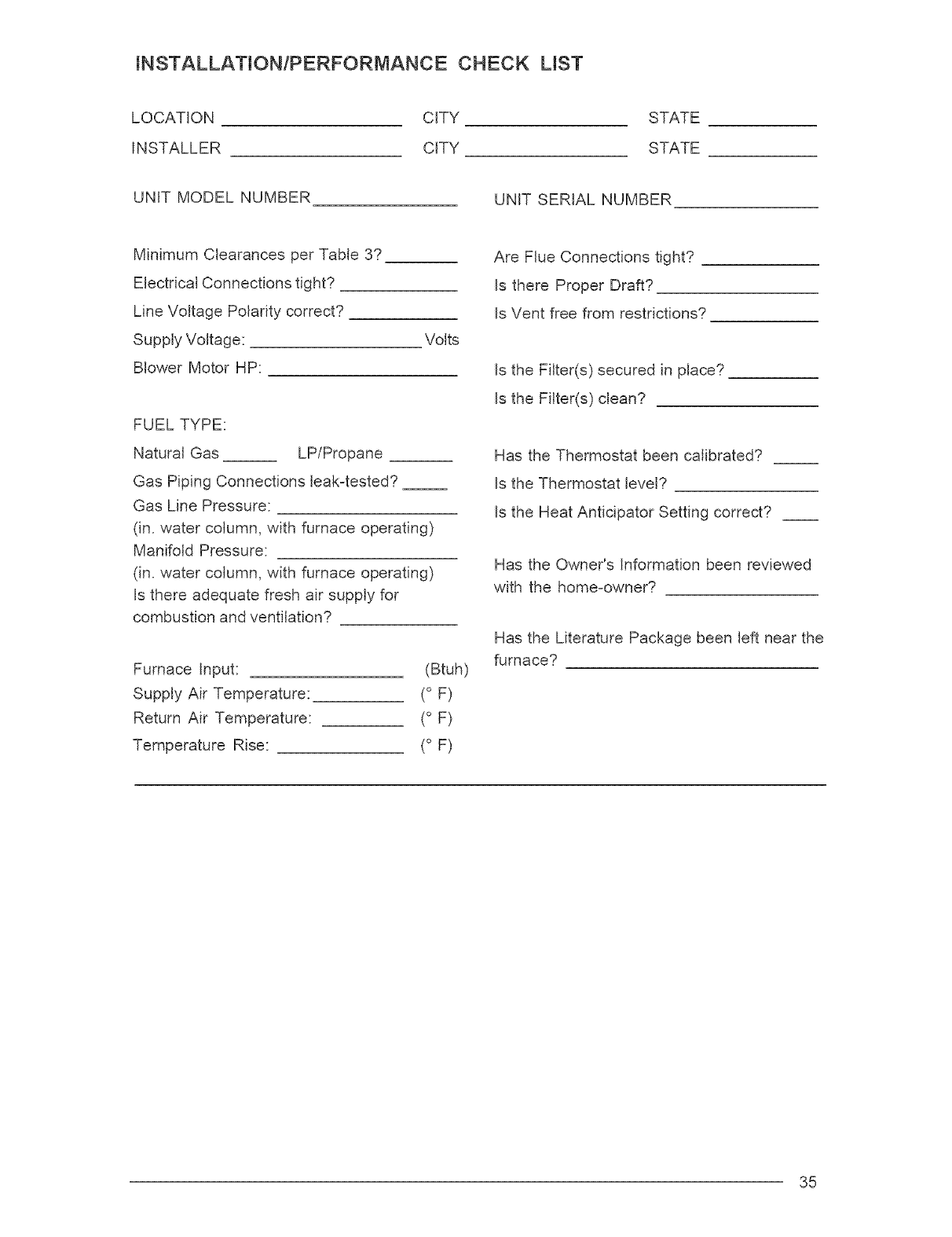
INSTALLATION/PERFORIVlANCE CHECK LIST
LOCATION CITY STATE
INSTALLER CITY STATE
UNIT MODEL NUMBER UNIT SERIAL NUMBER
Minimum Clearances per Table 3?
Electrical Connections tight?
Line Voltage Polarity correct?
Supply Voltage:
Blower Motor HP:
Volts
FUEL TYPE:
Natural Gas LPiPropane
Gas Piping Connections leak-tested? __
Gas Line Pressure:
(in. water column, with furnace operating)
Manifold Pressure:
(in. water column, with furnace operating)
Is there adequate fresh air supply for
combustion and ventilation?
Furnace Input:
Supply Air Temperature:
Return Air Temperature:
Temperature Rise:
(Btuh)
(° F)
(° F)
(° F)
Are Flue Connections tight?
Is there Proper Draft?
Is Vent free from restrictions?
Is the Filter(s) secured in place?
Is the Filter(s) clean?
Has the Thermostat been calibrated?
Is the Thermostat level?
Is the Heat Anticipator Setting correct?
Has the Owner's Information been reviewed
with the home-owner?
Has the Literature Package been left near the
furnace?
35

O'Fallon, MO NORDYNE
708219D
7082t9D (Replaces 708219C)
Specifications and illustrations subject to change without
notice and without incurring obligations. Printedin
US.A. (04/04)
