NORDYNE Furnace/Heater, Gas Manual L0612164
User Manual: NORDYNE NORDYNE Furnace/Heater, Gas Manual NORDYNE Furnace/Heater, Gas Owner's Manual, NORDYNE Furnace/Heater, Gas installation guides
Open the PDF directly: View PDF ![]() .
.
Page Count: 36

Direct Vent (Sealed Combustion) Forced Air Gas Furnaces
M2RC Series 90+ Upflow Condensing Furnace
M2RL Series 90+ Downflow Condensing Furnace
Upflow Model
/ WARNING:
Improper installation, adjustment,
alteration, service, or maintenance
can cause injury or property damage.
Refer to this manual for assistance.
For additional information consult a
qualified installer, service agency, or
the gas supplier.
Do not store or use gasoline or
other flammable vapors and
liquids in the vicinity of this or
any other appliance.
Downflow Model
Do not try to light any appliance.
Do not touch any electrical
switch; do not use any phone in
your building,
Immediately call your gas supplier
from aneighbor's phone. Follow
the gas supplier's instructions.
if you cannot reach your gas
supplier, call the fire department.
Extinguish any open flame.
WARNING: Danger. Only qualified service
personnel shall be used to install and provide
maintenance to this appliance.
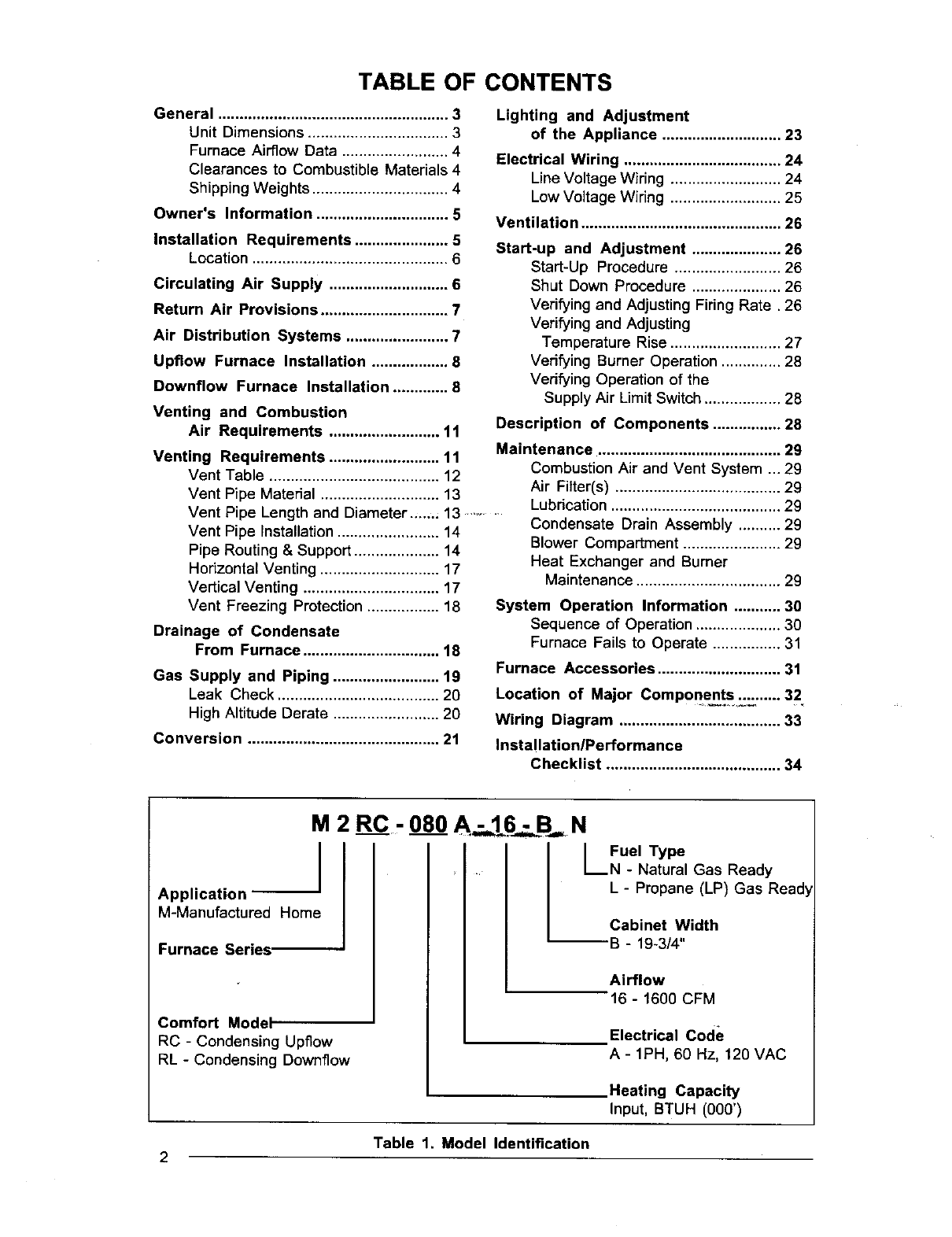
TABLE OF CONTENTS
General ...................................................... 3
Unit Dimensions ................................. 3
Furnace Airflow Data ......................... 4
Clearances to Combustible Materials 4
Shipping Weights ................................ 4
Owner's Information ............................... 5
Installation Requirements ...................... 5
Location .............................................. 6
Circulating Air Supply ............................ 6
Return Air Provisions .............................. 7
Air Distribution Systems ........................ 7
Upfiow Furnace Installation .................. 8
Downflow Furnace Installation ............. 8
Venting and Combustion
Air Requirements .......................... 11
Venting Requirements .......................... 11
Vent Table ........................................ 12
Vent Pipe Material ............................ 13
Vent Pipe Length and Diameter....., 13 .........
Vent Pipe Installation ........................ 14
Pipe Routing & Support .................... 14
Horizontal Venting ............................ 17
Vertical Venting ................................ 17
Vent Freezing Protection ................. 18
Drainage of Condensate
From Furnace ................................ 18
Gas Supply and Piping ......................... 19
Leak Check ...................................... 20
High Altitude Derate ......................... 20
Conversion ............................................. 21
Lighting and Adjustment
of the Appliance ............................ 23
Electrical Wiring ..................................... 24
Line Voltage Wiring .......................... 24
Low Voltage Wiring .......................... 25
Ventilation ............................................... 26
Start-up and Adjustment ..................... 26
Start-Up Procedure ......................... 26
Shut Down Procedure ..................... 26
Verifying and Adjusting Firing Rate. 26
Verifying and Adjusting
Temperature Rise .......................... 27
Verifying Burner Operation .............. 28
Verifying Operation of the
Supply Air Limit Switch .................. 28
Description of Components ................ 28
Maintenance ........................................... 29
Combustion Air and Vent System ... 29
Air Filter(s) ....................................... 29
Lubdcation ........................................ 29
Condensate Drain Assembly .......... 29
Blower Compartment ....................... 29
Heat Exchanger and Burner
Maintenance .................................. 29
System Operation Information ........... 30
Sequence of Operation .................... 30
Furnace Fails to Operate ................ 31
Furnace Accessories ............................. 31
Location of Major Components._._ '...... 32
Wiring Diagram ...................................... 33
Installation/Performance
Checklist ......................................... 34
M 2 RC.- 080 N
IFuel Type
•I_N - Natural Gas Ready
Application
M-Manufactured Home
Furnace Series,
Comfort Model
RC - Condensing Upflow
RL -Condensing Downflow
L-Propane (LP) Gas Read_
Cabinet Width
--B - 19-3/4"
Airflow
16 - 1600 CFM
Electrical Code
A-1PH, 60 Hz, 120 VAC
Heating Capacity
Input, BTUH (000')
Table 1. Model Identification
2
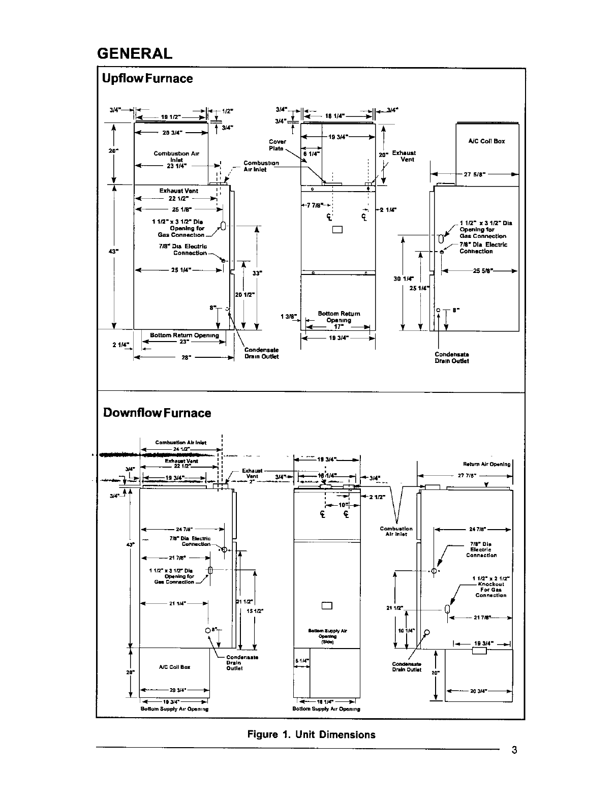
GENERAL
Upflow Furnace
Cover
Plate
Combusbon Air
Inlet J_l Combustion
23 1'4" -- Airln_et --
L/
1 3/8"
2 t,4" Condensate
4-- Drain Outlet
6 114"
_.: rt
r7
9 n
Bottom Ream
Opening
-- 19 314"_
Exhaust
Vent
A/C Coil Box
--27 5,8"
Gas Connection
Condensata
Drain Outlet
Downflow Furnace
i
Combust;cm Air Inlet I
i
'_ i I Exhaul_ ,.
_,-_ : -_,
i
2
_l_ 24 718"
1 I/2" T
21 114"_ t5t/2.
°+,,,,o. 1111llt@
,(-_ 19 3/4" _1
Norton Supply Air O_0emng
10_
k_ 8UpldyAk
O_nm.g
(S_ I
Sl/4'
Bottom Supply Atr Open nt
I-3/4-
Combustion
Air Inlet
RetumAirOpenln
-- 27 718"--
, Y
718" Die
Electric
Connection
"_" 11/2. x2 tl2 .
?
21 1/2"
Figure 1. Unit Dimensions
3
IMPORTANT:READALL INSTRUCTIONS
CAREFULLYBEFOREBEGINNINGTHE
INSTALLATION.
/ WARNING:
Do not use this product if any part has
been submerged under water.
Immediately call a qualified service
technician to inspect the appliance and
to replace any part of the control system
and any gas control that has been
submerged under water.
ified service technician periodically check allwiring
connections and service unit as required.
The M2 sedes gas furnaces are listed drect vent
(sealed combustion) forced air furnaces (type
FSP) for use with both natural and propane (LP)
gases. The M2 furnace series has been certi-
fied to the UL 307B standard for use in the United
States and to ANSI Z21.47a-CAN/CGA-2.3a-
1995 for use in the United States and Canada.
These furnaces may be installed in:
1. Manufactured Homes
2, Recreational Vehicles, Park Models
3. Manufactured Buildings
/ WARNING:
Should overheating occur, or the gas
fail to shut off, shut offthe manual gas
valve to the appliance before shutting
off the electrical supply.
NOTICE: Leave these instructions withthe home-
owner. Advise unit owner/user to follow the main-
_ter]ance rrecommendations outlined. Have a qual-
4. Modular Homes /Buildings
The M2 furnace is not to be used for the tempo-
rary heating of buildings under construction.
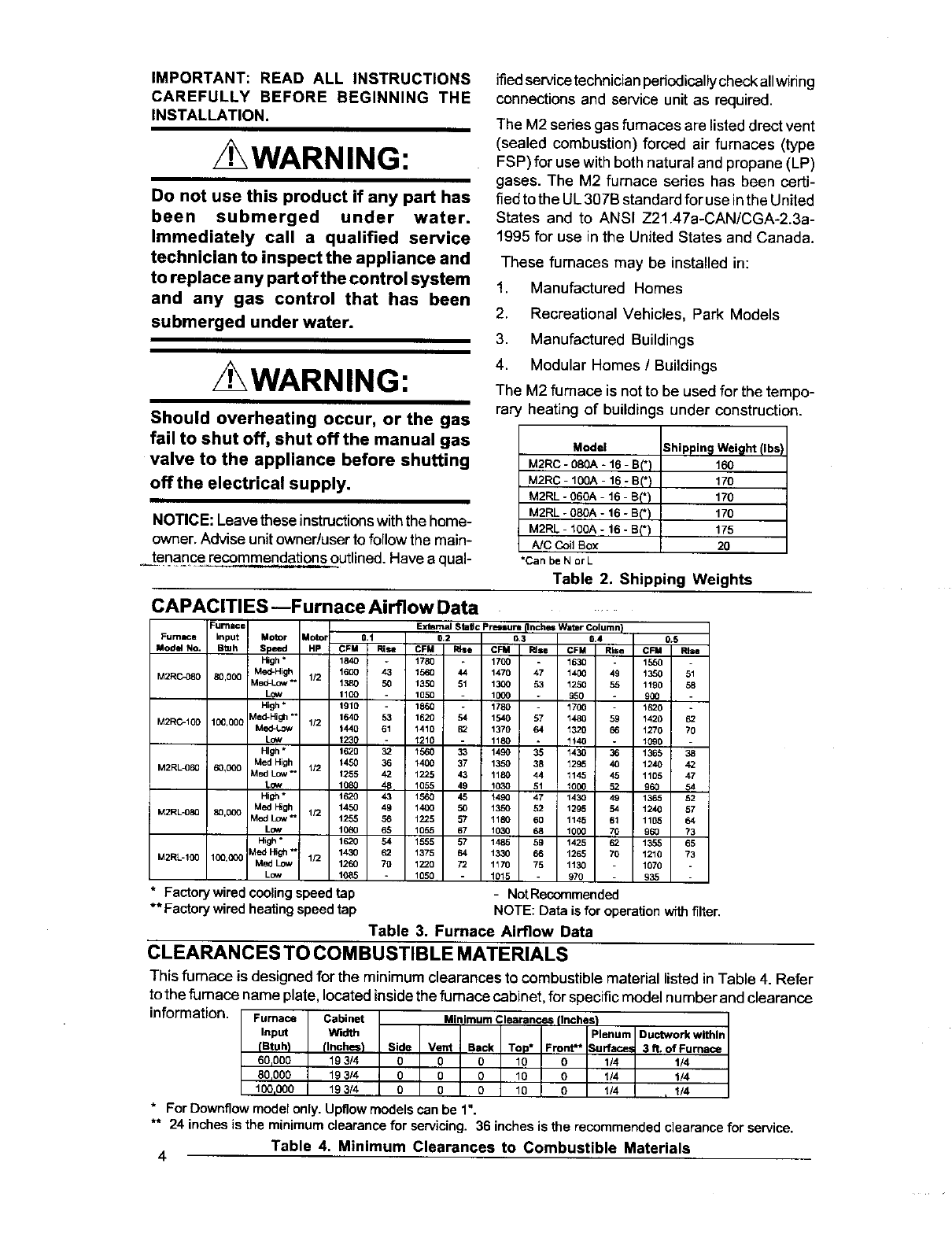
Model Shipping Weight (Ibs)
M2RC - 080A * 16 -B_*) 160
M2RC -1OOA-16 -S(*) 170
M2RL - O60A-16 -B(*) 170
M2RL - 080A -16 - B(*) 170
M2RL -100A - 16 -B(*) 175
A]C Coil Box 20
•Can be N orL
Table 2. Shipping Weights
CAPACITIES --Furnace Airflow Data
Furnace
Furnace input Motor _oto; 0.t
Model No. B_uh Speed HP CFM Rise
High * 1840 *
M2RO-OSO 80,000 Meal-High 1/2 1600 43
Med-Lcw *' 1380 50
Low 1100
High * 1910 -
M2RC-100 100,000 Meal-High "1640 53
Med-Low 1/2 1440 61
Low 1230 -
High * 1620 32
Med High 1450 36
M2RL_60 60,000 Med Low *' 1/2 1255 42
Low 1080 48
High" 1620 43
Med High 1450 49
M2R L-089 8_,000 Med Low _1/2 1255 56
L_ 1080 65
High* 1620 54
Meal High " 1430 62
M2RL-100 100,000 Med Low 112 1260 70
Low 1085
•Factorywired cc_ling speed tap
•* Factory wired heating speed tap
Exkrnal stage Pr,_sure (Inches Water Column}
0.2 0.3 0.4 0.5
CFM I_se CFM Rise CFM Rise CFM Rise
1780 -1700 -1630 -1550 -
1560 44 1470 47 1400 49 1350 51
1350 51 1300 53 1250 55 1190 58
1050 1000 950 900
1860 - 1780 - 1700 - 1620 -
1620 54 1540 57 1480 59 1420 62
1410 62 1370 64 1320 66 1270 70
1210 -1180 - 1140 . 1090 -
1560 33 1490 35 1430 36 1365 38
1400 37 1350 38 1295 40 1240 42
1225 43 1180 44 1145 45 1105 47
1055 49 1030 51 1000 52 960 54
1560 45 1490 47 1430 49 1365 52
1400 50 1350 52 1295 54 1240 57
1225 57 1180 60 1145 61 1105 64
1055 67 1030 68 1000 70 960 73
1555 57 1485 59 1425 62 1355 65
1375 64 1330 66 1265 70 1210 73
1220 72 1170 75 1130 1070
1050 1015 970 935
-NotRecommended
Table 3.
NOTE:Datais for operationwfth filter.
Furnace Airflow Data
CLEARANCES TO COMBUSTIBLE MATERIALS
This furnace is designed for the minimum clearances to combustiblematerial listed in Table 4. Refer
tothe fumace name plate, locatedinside the furnace cabinet,for specificmodel numberand clearance
information. Furnace Cabinet Minimum Clearances (Inches}
Input Width Plenum Ductwork within
(Stuh} flnches_ Side Vent Back Top* Front** Surfac_ 3 fL of Furnace
60,000 19314 O O0 10 0 1/4 1/4
80,000 193/4 O O O 10 O1/4 1/4
100,000 193/4 0 O0 19 0 1/4 , 1/4
* For Downflow model only. Upflow models can be 1".
** 24 inches is the minimum clearance for servicing. 36 inches is the recommended clearance for service.
Table 4. Minimum Clearances to Combustible Materials
4
NOTICE TO INSTALLER
Installer is advised to follow carefully all in-
structions and warnings in this manual to in-
sure maximum performance, safety, and oper-
ating efficiency of these appliances. Improper
installation may create hazardous conditions,
and will void the appliance warranty.
Manufacturer Warranty, Owner's
Responsibilities
It is the sole responsibility of the homeowner to
make certain the gas furnace has been cor-
rectly installed in the home, converted to the
proper fuel (LP gas or Natural gas), and ad-
justed for proper operation.
OWNER'S INFORMATION
About Your Central Furnace System
NORDYNE has been involved in the design of
products for the manufactured home industry
since the first manufactured home or trailer
was built.
NORDYNE originated the sealed combustion
system, which separates the furnace com-
bustion system from the living area of the home
and is now a standard for the manufactured
home industry.
NORDYNE engineers developed the first cen-
tral heating system and the first central air
conditioner for manufactured homes.
NORDYNE is dedicated to bringing to its cus-
tomers the finest heating and cooling comfort
possible. NORDYNE constantly seeks to fur-
ther refine its products to continuously provide
exceptional comfort.
Awarranty certificate with full details is in-
cluded with this furnace. However, NORDYNE
will not be responsible for any costs found
necessary to correct problems due to im-
proper setup, improper installation, furnace
adjustments, improper operating procedure
on the part of the user, etc.
Some specific examples of service calls which
cannot be included in warranty payments are:
1. Converting the furnace to use another
type of gas.
2. Repairing duct work in the home found to
be faulty.
3. Correcting wiring problems in the electri-
cal circuit supplying the furnace.
4. Resetting circuit breakers, blown fuses
or other switches.
5. Correcting problems due to improper gas
supply pressure to the furnace.
6. Providing instructional training on how to
light and operate the furnace.
7. Correcting any problems caused by in-
stallation of an air conditioner, heat pump
or other air comfort devices.
Follow the instructions in this booklet carefully 8. Revising installation of the furnace flue
and this appliance will provide many years _of ......... assembly: ..............................
superior performance. 9. Adjusting or calibrating of thermostat.
Ifyou wish to cool your home automatically with
a central air conditioning system investigate
the excellent NORDYNE cooling systems avail-
able from your heating and cooling contractor.
These systems are designed to work best with
your NORDYNE furnace and have been care-
fully engineered to deliver optimal performance
when mated with NORDYNE manufactured
home furnaces.
NORDYNE also offers water heaters, fire-
places and ventilating systems specifically
designed for manufactured housing applica-
tions. Ask your manufactured home retailer,
10. Removing any construction debris which-
has fallen into flue system.
Carefully review these responsibilities with
your manufactured housing dealer, service
company, or gas supplier, so that there will be
no misunderstanding at a later time.
INSTALLATION REQUIREMENTS
Requirements and Codes:
The installer must be familiar with and comply
with all local codes and regulations applicable
to the installation of heating appliances and
related equipment. In the absence of local
your heat nn and coolin,_ contractor or your codes, the installation must conform with these
distributor for more information. Write directly instructions and the current provisierfs_'6f_one
to the factory (PO Box 46911, St. Louis, MO or more of the following standards:
63146) if you are unable to locate a source for a. Federal Manufactured Home
NORDYNE manufactured housing products in Constructions & Safety Standard (H.U.D.
your area. Title 24, Part 3280.707[a][2])
b. The Standardfor ManufacturedHome
Installations (Manufactured Home Sites,
Communities, and Set-Ups)ANSI A225.1
and/or CAN/CSA-2240 MH Series).
c. American National Standard (ANSI-
119.2/NFPA-501C) for all recreational
vehicle installations.
d. American National Standard (ANSI-
Z223.1/NFPA-54) and/or CAN/CGA
B149 for all gas-fired furnace models.
e. American National Standard (ANSI-C1/
NFPA-70) and/or CSA 22.1 Canadian
Electric Code Part 1 for all electrical field
wiring.
CE g6nerateur d'air chaud dolt 6tre insta]l_
conform6ment aux instructions du fabricant et
aux codes Iocaux. En I'absence de code local,
respecter la norme ANSI Z223.,1, institule Na-
tional Fuel Gas Code ou les codes d'installation
CAN/GCA-B 149.
The National Fuel Gas Code is available by
writing:
able and allow the appropriate clearance for
your installation.
This furnace is certified for use on wood
flooring. The furnace must be installed on a
solid surface and must be level front to back
and side to side. This furnace must not be
installed directly on carpeting, tile, or any
combustible material other than wood flooring.
Downflow models can only be installed on
combustible flooring when installed on a
Nordyne plenum base (part numbers 901987
through 901993 - see Table 5). Both the upflow
and downflow models must be installed with
the Nordyne A,'C coil box (part no. 914958).
The plenum attached to the A,'C coil box and
the ductwork within 3 feet of the furnace must
be installed such that surfaces are at least
1/4" from combustible construction.
CIRCULATING AIRSUPPLY
General
Plenums and air ducts must be installed in
AmericanNationaIStandardslnstitute,lnc. 'accordance with the Standard for the
1430 Broadway Installati0n of Air Conditioning and Ventilating
New York, NY 10018 Systems (NFPA No. 90A) or the Standard for
the Installation of Warm Air Heating and Air
NFPA publications are available by writing: Conditioning Systems (NFPA No. 90B).
National Fire Protection Association
Batterymarch Park
Quincy, ME 02269
Location
The furnace must be installed on a level sur-
face, and as close to the center of the air
distribution system as possible. See Figure 1
for overall dimensions to determine the re-
quired clearances in hallways, doorways, stairs,
etc. to allow the furnace to be moved to the
installation point. The furnace must be installed
so that all electrical components are protected
from water.
Minimum clearances to combustible materials
are listed in Table 4. Access for positioning and
servicing must be considered when locating
the unit. 24 inches is the minimum required
clearance for servicing the unit. 30 inches is the
minimum required clearance for positioning the
unit. 36 inches is the recommended clear-
ance from the front of the unit. Please note
that a panel or door can be located such that
the minimum clearance on the rating plate is
satisfied, but that panel or door must be remov-
/ WARNING:
Products of combustion must not be
allowed to enter the return air openings
of the furnace or the circulating airsupply,
Failure to prevent products of
combustion from being circulated into
the living space can create potentially
hazardous conditions including carbon
monoxide poisoning that could result in
personal injury or death.
The floor or platform on which the fumace
is mounted must provide sound physical
support of the furnace with no gaps,
cracks, or sagging between the furnace
and the floor or platform.
The circulating air ductwork must not be
connected to any other heat producing
device such as a fireplace insert, stove,
etc.
RETURN AIR PROVISIONS
Upfiow models draw the return air from the
base of the furnace. A stand or return air duct
must be supplied to the furnace to provide the
required return air.
Downflow models draw the return air from the
top of the furnace. The minimum required
clearance to the top of the furnace is detailed
on the furnace rating plate. Additional clear-
ance may be required depending upon filter
accessibility.
For each application, the U.S.A. home manufac-
turer shall comply with all of the following condi-
tions to have acceptable retum air systems for
closet installed forced air heating appliances:
a. Regardless of the location, the return air
opening into the closet shall not be less
than specified in the appliance's listing.
b. Means shall be provided to prevent
inadvertent closure by a flat object placed
over the return air opening when it is
located in the floor of the closet (versus
the vertical front or side wall).
c. The cross-sectional area of the return
duct system leading into the closet shall
not be less than 390 square inches.
d. The total free area of openings in the floor
or ceiling registers serving the return air
duct system must be at least 352 sq. in.
At least one register should be located
where it is not likely to be covered by
For floor return systems, the
manufactured home manufacturer shall
affix a prominent marking on or near the
appliance where it can be easily read
when the closet door is open. The
marking shall read:
CAUTION:
HAZARD OF ASPHYXIATION: Do not
cover or restrict return air opening.
k. Air conditioning systems may require
more duct, register and open louver area
to obtain necessary airflow. Use
NORDYNE's certiduct program to
determine proper duct size for A/C.
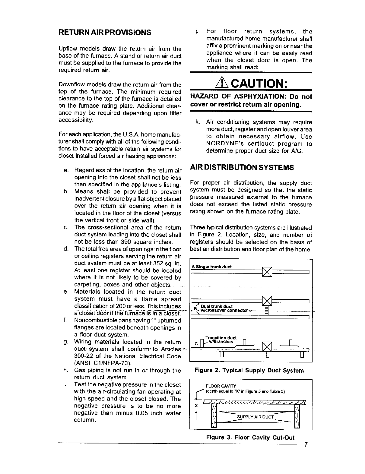
AIR DISTRIBUTION SYSTEMS
For proper air distribution, the supply duct
system must be designed so that the static
pressure measured external to the furnace
does not exceed the listed static pressure
rating shown on the furnace rating plate.
Three typical distribution systems are illustrated
in Figure 2. Location, size, and number of
registers should be selected on the basis of
best air distribution and floor plan of the home.
A Single trunk duct []
carpeting, boxes and other objects ............................................................
e. Materials located in the return duct
system must have a flame spread
classification of 200 or less. This includes
a-closetdo0r if theefu-rnac_ is"fna-cios_t._
f. Noncombustible panshaving 1"upturned
flanges are located beneath openings in
afloor duct system.
g. Wiring materials located in the return
duct,system shall conform_to Articles ,-
300-22 of the National Electrical Code
(ANSI CI/NFPA-70).
h. Gas piping is not run in or through the
return duct system.
i. Test the negative pressure in the closet
with the air-circulating fan operating at
high speed and the closet closed. The
negative pressure is to be no more
negative than minus 0.05 inch water
column.
BJ Dual trunk duct _ ]
- _ wlcrossover connector-_- •
J
U U U
Figure 2. Typical Supply Duct System
FLOOR CAVITY
U(depth equal to "X* in F3gure 5 and Table 5)
tJJJJJJJJJJJJJJJJJJJJJ JJ _JJi_
x-l--- -----.._ il ,l
II)J SuPPLYAiRoucT
-- I_! /k h\l
Figure 3. Floor Cavity Cut-Out 7
If "X"
(Floor cavity) is:
7/8" (22ram)
2" (51ram)
4 1/4" (108ram)
6 1/4" (159rnm)
8 1/4" (210mm)
10 1/4" (260ram)
12 1/4" (311mm)
Use Duct
Connector Model
901987
901988
901989
901990
901991
901992
901993
Table 5. Duct Connectors
1-10li,,
, 1
Figure 4. Top View of Duct Connector
OPENING TO DUCT
WITH pLATE {C) REMOVED
13-1/4" x 13-1/4"
OPENING BECOMES
Figure 5. Duct Connector
UPFLOWFURNACE
INSTALLATION
a. Position the furnace on top of the return
air ductwork or return air stand. NOTE:
The ductwork or stand must have an
opening equal to that of the return air
opening of the furnace. Refer to Figure 1
for the proper return air opening size.
Secure the furnace to the floor or base
once it has been properly positioned.
b. Position and secure the A/C coil box to
the top of the furnace. The A/C coil box
C.
d.
can be secured to the furnace using the
provided attachment brackets. These
brackets are designed to attach the
furnace cabinet to the A/C coil box on the
sides. To install these brackets, position
one bracket on the side of the furnace,
so that the locating dimples are in the
groove created by the top of the furnace
cabinet and the bottom of the A/C coil
box. Using the provided self-drilling
screws, secure the bracket to the A/C
coil box and the furnace. Repeat on the
other side of the furnace for the other
bracket.
Attach the plenum from the supply duct
to the flanges of the A/C coil box.
Secure the plenum to the supply
ductwork.
NOTE: Additional fasteners may be used
at rear, sides or through door frame, as
desired, to secure furnace to closet or
alcove framing.
DOWNFLOWFURNACE
INSTALLATION
DUCT CONNECTOR SELECTION FOR
DOWNFLOW MODELS
a. Determine depth of floor cavity from
surface of floor to top of supply air duct
(See Figure 3).
b. Select appropriate model from Table 5
which matches X-dimension of the floor
cavity. To maximize air delivery, remove
reducer "C" (see Figure 5) to obtain the
largest open area that will fit the duct/
floor construction.
INSTALLATION OF THE DUCT CONNEC-
TOR FOR DOWNFLOW INSTALLATIONS
Required cut-out openings in the floor, ceiling,
roof, and/or walls must be carefully located to
avoid misalignment of the furnace, combustion
air piping, and vent piping (see Figures 14-16).
Installation procedures are suggested for
typical furnace installations and need not be
followed in the exact listed sequence.
CUT OUT FLOOR OPENING FOR
DOWNFLOW MODELS
a. Determine center of closet or alcove
(Figure 7).
b. Locate center of the floor opening, mea-
sured 10" from the rear wall, and mark
cut-out measuring approximately 14-1/
2" by 14-1/2" (+ 1") for model duct
connector used (refer to Figures 6 & 7).
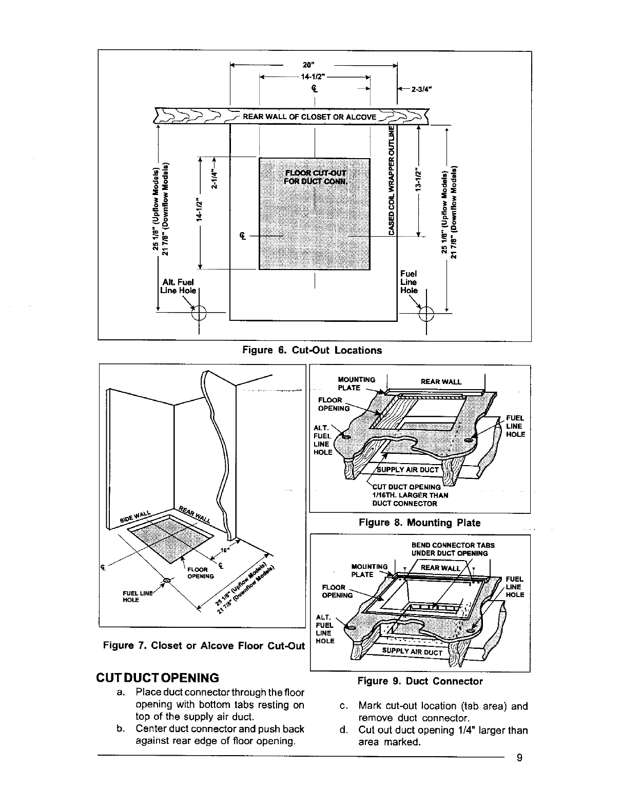
Figure 6. Cut-Out Locations
HOLE
Figure 7. Closet or Alcove Floor Cut-Out
MOUNTING
PLATE REAR WALL
f
FUEL
1/16TH. LARGER THAN
DUCT CONNECTOR
Figure 8, Mounting Plate
BEND CONNECTOR TABS
UNDER DUCT OPENING
MOUNTING
PLATE
FLOOR
CUTDUCTOPENING
a. Place duct connectorthroughthe floor
b.
Figure 9. Duct Connector
opening with bottom tabs resting on
top of the supply air duct.
Center duct connector and push back
against rear edge of floor opening.
c. Mark cut-out location (tab area) and
remove duct connector.
d. Cut out duct opening 1/4" larger than
area marked.
9
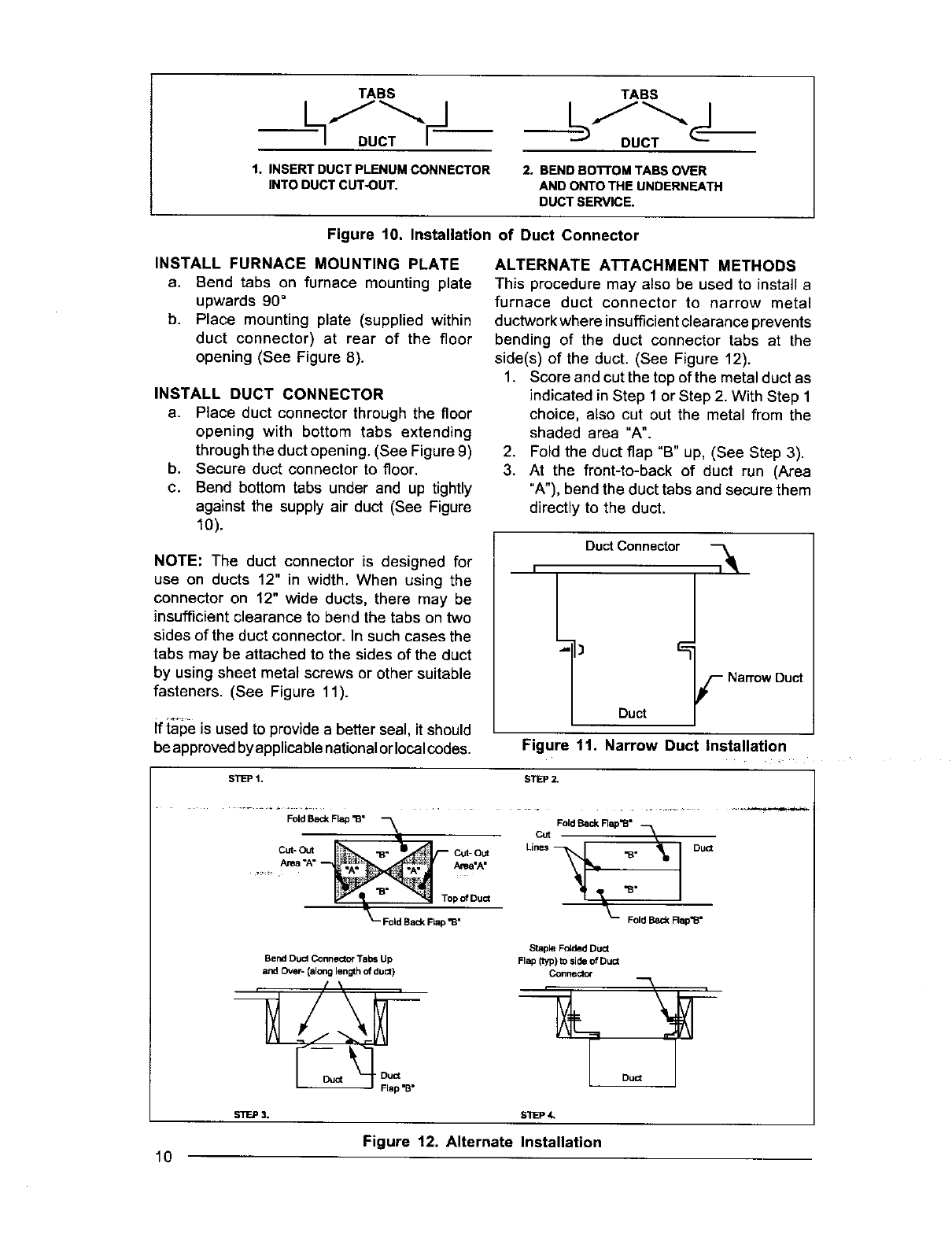
TABS TABS
-- DUCT _DUCT
1. INSERT DUCT PLENUM CONNECTOR
INTO DUCT CUT-OUT. 2. BEND Bo'n'OM TABS OVER
AND ONTO THE UNDERNEATH
DUCTSER_CE.
Figure 10. Installation of Duct Connector
INSTALL FURNACE MOUNTING PLATE
a. Bend tabs on furnace mounting plate
upwards 90°
b. Place mounting plate (supplied within
duct connector) at rear of the floor
opening (See Figure 8).
INSTALL DUCT CONNECTOR
e. Place duct connector through the floor
opening with bottom tabs extending
through the duct opening. (See Figure 9)
b. Secure duct connector to floor.
c. Bend bottom tabs under and up tightly
against the supply air duct (See Figure
10).
NOTE: The duct connector is designed for
use on ducts 12" in width. When using the
connector on 12" wide ducts, there may be
insufficient clearance to bend the tabs on two
sides of the duct connector. In such cases the
tabs may be attached to the sides of the duct
by using sheet metal screws or other suitable
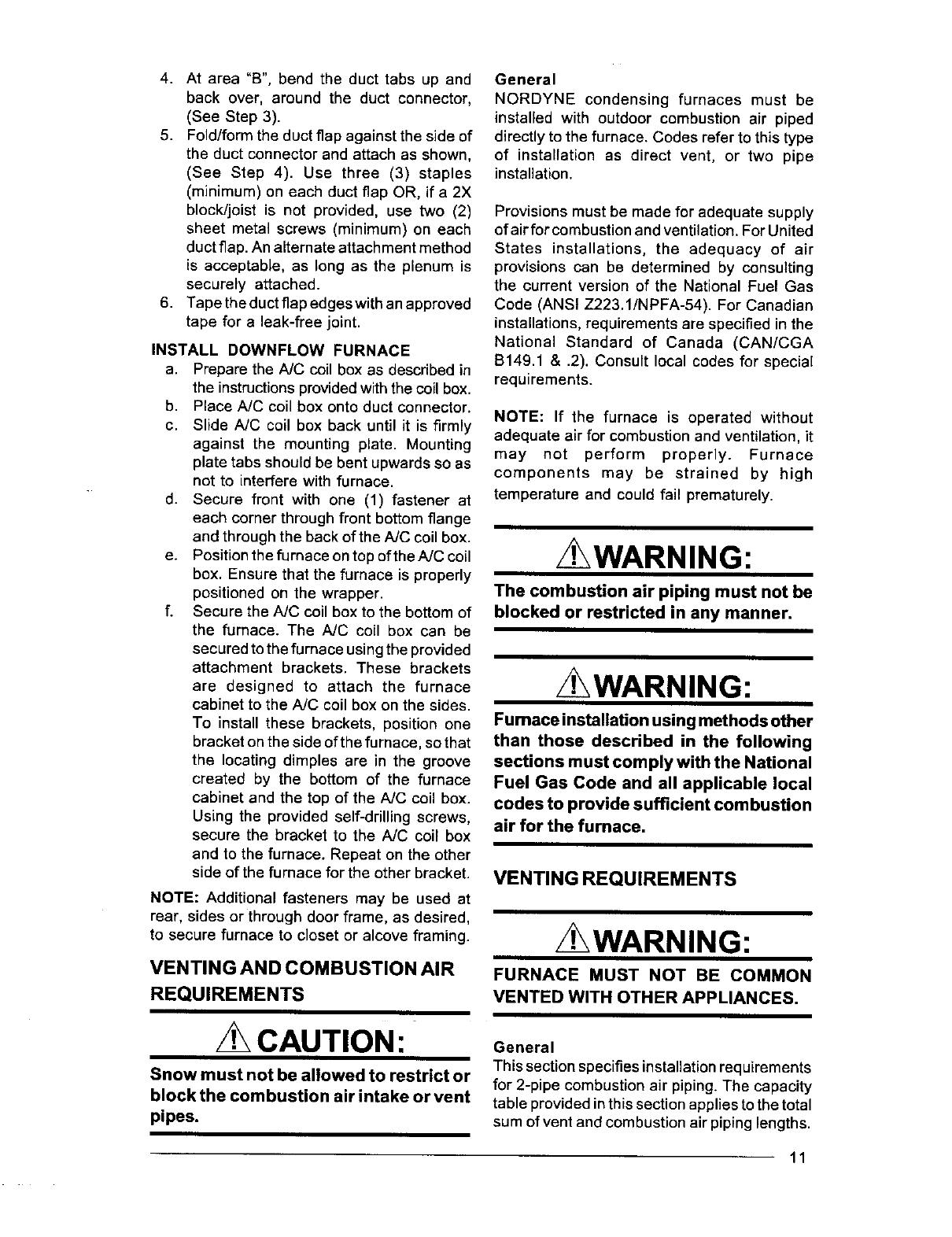
fasteners. (See Figure 11).
if ial_e is used to provide a better seal, it should
be approved by applicable national orlocal codes.
ALTERNATE ATTACHMENT METHODS
This procedure may also be used to install a
furnace duct connector to narrow metal
ductworkwhere insufficientclearance prevents
bending of the duct connector tabs at the
side(s) of the duct. (See Figure 12).
1. Score and cut the topof the metal duct as
indicated in Step 1 or Step 2. With Step 1
choice, also cut out the metal from the
shaded area "A".
2. Fold the duct flap "B" up, (See Step 3).
3. At the front-to-back of duct run (Area
"A"), bend the duct tabs and secure them
directly to the duct.
Duct Connector "--_
I
Duct
fNa_ow
Figure 11. Narrow Duct Installation
Duct
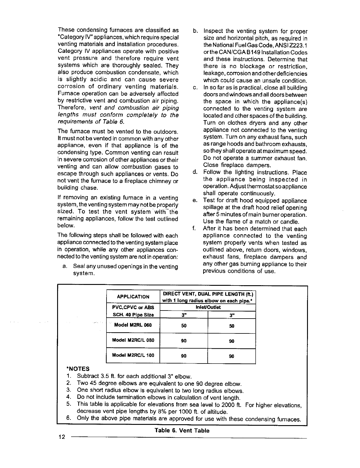
STEP 1. STEP 2,
Fold Back Flap "B" Cut Fold _Rap'B"
"' _a "O_A" "B" I
_Fold Back Rap "B. _-- Fold Back Flap'B"
Bend DUCt Connector Tabs Up
and Over- (alonglengthof duct)
Stapk_ Folded Duct
Flap (lypl _0,_ide of Du_
Connector
Duct
STEP 3. S1]EP 4.
Figure 12. Alternate Installation
10
4. At area"B",bendtheducttabsupand
backover,aroundthe duct connector,
(SeeStep3).
5. Fold/formtheductflapagainstthesideof
theductconnectorand attach as shown,
(See Step 4). Use three (3) staples
(minimum) on each duct flap OR, if a 2X
block/joist is not provided, use two (2)
sheet metal screws (minimum) on each
duct flap. An alternate attachment method
is acceptable, as long as the plenum is
securely attached.
6. Tape the duct flap edges with an approved
tape for a leak-free joint.
INSTALL DOWNFLOW FURNACE
a. Prepare the NC coil box as described in
the instructionsprovidedwith the coil box.
b. Place A/C coil box onto duct connector.
c. Slide A/C coil box back until it is firmly
against the mounting plate. Mounting
plate tabs should be bent upwards so as
not to interfere with furnace.
d. Secure front with one (1) fastener at
each corner through front bottom flange
and through the back of the A/C coil box.
e. Position the furnace ontop ofthe A/C coil
box. Ensure that the furnace is properly
positioned on the wrapper.
f. Secure the A/C coil box to the bottom of
the furnace. The A/C coil box can be
secured to the furnace using the provided
attachment brackets. These brackets
are designed to attach the furnace
cabinet to the AJC coil box on the sides.
To install these brackets, position one
bracket on the side of the furnace, so that
the locating dimples are in the groove
created by the bottom of the furnace
cabinet and the top of the A/C coil box.
Using the provided self-drilling screws,
secure the bracket to the A/C coil box
and to the furnace. Repeat on the other
side of the furnace for the other bracket.
NOTE: Additional fasteners may be used at
rear, sides or through door frame, as desired,
to secure furnace to closet or alcove framing.
VENTING AND COMBUSTION AIR
REQUIREMENTS
CAUTION:
Snow must not be allowed to restrict or
block the combustion air intake or vent
pipes.
General
NORDYNE condensing furnaces must be
installed with outdoor combustion air piped
directly to the furnace, Codes refer to this type
of installation as direct vent, or two pipe
installation.
Provisions must be made for adequate supply
of air for combustion and ventilation. For United
States installations, the adequacy of air
provisions can be determined by consulting
the current version of the National Fuel Gas
Code (ANSI Z223.1/NPFA-54). For Canadian
installations, requirements are specified in the
National Standard of Canada (CAN/CGA
B149.1 & .2). Consult local codes for special
requirements.
NOTE: If the furnace is operated without
adequate air for combustion and ventilation, it
may not perform properly. Furnace
components may be strained by high
temperature and could fail prematurely.
WARNING:
The combustion air piping must not be
blocked or restricted in any manner,
z WARNING:
Fumace installation using methods other
than those described in the following
sections must comply with the National
Fuel Gas Code and all applicable local
codes to provide sufficient combustion
air for the fumace,
VENTING REQUIREMENTS
/t',WARNING:
FURNACE MUST NOT BE COMMON
VENTED WITH OTHER APPLIANCES.
General
This section specifies installation requirements
for 2-pipe combustion air piping. The capacity
table provided in this section applies to the total
sum of vent and combustion air piping lengths.
11
Thesecondensing furnaces are classified as
"Category IV"appliances, which require special
venting materials and installation procedures.
Category IV appliances operate with positive
vent pressure and therefore require vent
systems which are thoroughly sealed. They
also produce combustion condensate, which
is slightly acidic and can cause severe
corrosion of ordinary venting materials.
Furnace operation can be adversely affected
by restrictive vent and combustion air piping.
Therefore, vent and combustion air piping
lengths must conform completely to the
requirements of Table 6.
The furnace must be vented to the outdoors.
It must not be vented in common with any other
appliance, even if that appliance is of the
condensing type. Common venting can result
in severe corrosion of other appliances or their
venting and can allow combustion gases to
escape through such appliances or vents. Do
not vent the furnace to afireplace chimney or
building chase.
If removing an existing furnace in a venting
system, the venting system may not be propedy
sized. To test the vent system with'-the
remaining appliances, follow the test outlined
below.
The following steps shall be followed with each
appliance connected to the venting system place
in operation, while any other appliances con-
nected to the venting system are not in operation:
a. Seal any unused openings in the venting
system.
b. Inspect the venting system for proper
size and horizontal pitch, as required in
the National Fuel Gas Code, ANSI Z223.1
orthe CAN/CGA B149 Installation Codes
and these instructions. Determine that
there is no blockage or restriction,
leakage, corrosion and other deficiencies
which could cause an unsafe condition.
c. In so far as is practical, close all building
doors and windows and all doors between
the space in which the appliance(s)
connected to the venting system are
located and other spaces of the building.
Turn on clothes dryers and any other
appliance not connected to the venting
system. Turn on any exhaust fans, such
as range hoods and bathroom exhausts,
so they shall operate at maximum speed.
Do not operate a summer exhaust fan.
Close fireplace dampers.
d. Follow the lighting instructions. Place
the appliance being inspected in
operation. Adjust thermostat so appliance
shall operate continuously.
e. Test for draft hood equipped appliance
spillage at the draft hood relief opening
after 5 minutes of main burner operation.
Use the flame of a match or candle.
f. After it has been determined that each
appliance connected to the venting
system properly vents when tested as
outlined above, return doors, windows,
exhaust fans, fireplace dampers and
any other gas burning appliance to their
previous conditions of use.
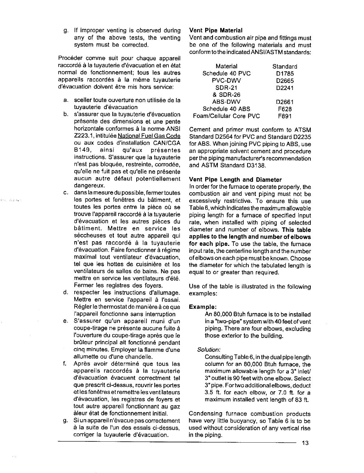
APPLICATION
PVC, CPVC or ABS
SCH. 40 Pipe Size
Model M2RL 060
Model M2RCIL 080
Model M2RC/L 100
DIRECT VENT, DUAL PIPE LENGTH (ft.)
with 1 long radius elbow on each pipe.*
Inlet/Outlet
3==
50
90
90
3 ID
5O
9O
9O
*NOTES
1. Subtract 3.5 ft. for each additional 3" elbow.
2. Two 45 degree elbows are equivalent to one 90 degree elbow.
3. One short radius elbow is equivalent to two long radius elbows.
4. Do not include termination elbows in calculation of vent length.
5. This table is applicable for elevations from sea level to 2000 ft. For higher elevations,
decrease vent pipe lengths by 8% per 1000 ft. of altitude.
6. Only the above pipe materials are approved for use with these condensing furnaces.
Table 6. Vent Table
12
g. If improperventingis observedduring
any of the abovetests, the venting
systemmustbe corrected.
Proc6dercommesuit pourchaqueappareil
raccord6ala tuyauterie d'_vacuation et en _tat
normal de fonctionnement; tous les autres
appareils raccordes & la meme tuyautede
d'_vacuation doivent _tre mis hors service:
a. sceller toute ouverture non utilis6e de la
tuyauterie d'evacuation
b. s'assurer que la tuyautede d'6vacuation
pr6sente des dimensions et une pente
horizontale conformes & la norme ANSI
Z223.1, intitul_e National Fuel Gas Code
ou aux codes d'installetion CAN/CGA
B149, ainsi qu'aux pr_sentes
instructions. S'assurer que la tuyauterie
n'est pas bloqu6e, restreinte, corrodee,
qu'elle ne fuit pas et qu'elle ne pr6sente
aucun autre defaut potentiellement
dangereux.
c. dans la mesure du possible, fermertoutes
les pores et fen_tres du b&timent, et
toutes les portes entre la piece o_ se
trouve I'appareil raccorde _,la tuyauterie
d'_vacuation et les autres pieces du
b_timent. Mettre en service les
s6ccheuses et tout autre appareil qui
n'est pas raccord6 _ la tuyauterie
d'_vacuation. Faire fonctionner _ regime
maximal tout ventilateur d'6vacuation,
tel que les hottes de cuisini6re et les
ventilateurs de salles de bains. Ne pas
mettre en service les ventilateurs d'_t_.
Fermer les registres des foyers.
d. respecter les instructions d'allumage.
Mettre en service I'appareil & ressai.
R6gler le thermostat de mani_re &ce que
I'appareil fonctionne sans interruption
e. S'assurer qu'un appareil muni d'un
coupe-tirage ne pr6sente aucune fuite ._
rouverture du coupe-tirage apr_s que ie
bn31eur principal ait fonctionn_ pendant
cinq minutes. Employer la flamme d'une
allumette ou d'une chandelle.
f. Apres avoir d6termin_ que tousles
appareils raccord_s _ la tuyauterie
d'_vacuation evacuent correctment tel
que prescrit ci-dessus, rouvdr les portes
et les fen_tres et remettre les ventilateurs
d'_vacuetion, les registres de foyers et
tout autre appareil fonctionnant au gaz
_,leur etat de fonctionnement initial.
g. Si un appareil n'evacue pas correctement
_, la suite de Pun des essais ci-dessus,
corriger la tuyauterie d'6vacuation.
Vent Pipe Material
Vent and combustion air pipe and fittings must
be one of the following materials and must
conform tothe indicated ANSI/ASTM standards:
Material Standard
Schedule 40 PVC D1785
PVC-DWV D2665
SDR-21 D2241
& SDR-26
ABS-DWV D2661
Schedule 40 ABS F628
Foam/Cellular Core PVC F891
Cement and primer must conform to ATSM
Standard D2564 for PVC and Standard D2235
for ABS. When joining PVC piping to ABS, use
an appropriate solvent cement and procedure
per the piping manufacturer's recommendation
and ASTM Standard D3138.
Vent Pipe Length and Diameter
In order for the furnace to operate properly, the
combustion air and vent piping must not be
excessively restrictive. To ensure this use
Table 6, which indicatesthe maximumallowable
piping length for a furnace of specified input
rate, when installed with piping of selected
diameter and number of elbows. This table
applies to the length and number of elbows
for each pipe. To use the table, the furnace
input rate, the centerline lengthand the number
of elbows on each pipe must be known. Choose
the diameter for which the tabulated length is
equal to or greater than required.
Use of the table is illustrated in the following
examples:
Example:
An 80,000 Btuh furnace is to be installed
in a "two-pipe" system with 40 feet of vent
piping. There are four elbows, excluding
those exterior to the building.
Solution:
Consulting Table 6, in the dual pipe length
column for an 80,000 Btuh furnace, the
maximum allowable length for a 3" inlet/
3" outlet is 90 feet with one elbow. Select
3" pipe. For two additional elbows, deduct
3.5 ft. for each elbow, or 7.0 ft. for a
maximum installed vent length of 83 ft.
Condensing furnace combustion products
have very little buoyancy, so Table 6 is to be
used without consideration of any vertical rise
in the piping.
13
NOTE: Always use the same or larger size
piping for combustion air as is used for the
exhaust vent.
Vent Pipe Installation
Pipe Routing and Support
Route piping as directly as possible between
the furnace and the outdoors and remember
that routing affects pipe size requirements per
the preceding section. Locate the combustion
air intake and the vent exhaust in the same
atmospheric pressure zone - i.e. both must exit
the building though the same portion of exterior
wall or roof. Vent piping must be sloped upwards
not less than 1/4" per foot in the direction from
the furnace to the terminal. This is to ensure
that any condensate flows back to the furnace
(where it can be disposed of through the
condensate disposal system).
CAUTION:
Combustion air must not be drawn from
a corrosive atmosphere.
_]-he qua!ity of outdoor air must also be
considered. Be sure that the combustion air
intake is not located near asource of solvent
fumes or other chemicals which can cause
corrosion of the furnace combustion system.
Piping must be mechanically supported so that
itsweight does not bear on the furnace. Supports
must be at intervals no greater than five feet,
and at smaller intervals if necessary to ensure
that there are no sagging sections to trap water
(See Figures 14 & 15).
Figure 16 illustrates vent and combustion air
pipe sizes exiting the furnace. Transition to the
correct pipe size must be done close to the
furnace so that the full length of pipe is of proper
size.
These condensing furnaces have been certified
for installation with zero clearance between
vent piping and combustible surfaces. However,
it is good practice to allow space forconvenience
in installation and service.
Pipe Couplings at the Furnace
The provided rubber couplings should be in-
stalled in the combustion air (use 3" diameter
coupling) and vent (2" diameter) pipes to allow
for servicing. These couplings are designed to
fit snugly over the pipe and be secured to the
pipes using the provided hose clamps. Use 3"
x 2" flexible coupling at furnace on 2" vent pipe
and on upflow units use 3" diameter coupling
above coil box, as shown in Figures 14 and 15.
Refer to figures 14 and 15 for the proper
installation of these couplings.
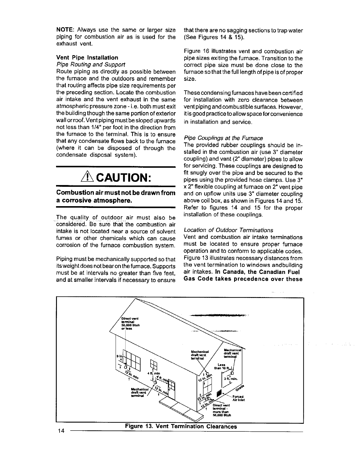
Location of Outdoor Terminations
Vent and combustion air intake terminations
must be located to ensure proper furnace
operation and to conform to applicable codes.
Figure 13 illustrates necessary distances from
the vent termination to windows andbuilding
air intakes. In Canada, the Canadian Fuel
Gas Code takes precedence over these
draft vent
termin_d /
Air Intet
Dite_ Vetlt
terminal -
more than
50,000 Btuh
Figure 13. Vent Termination Clearances
14
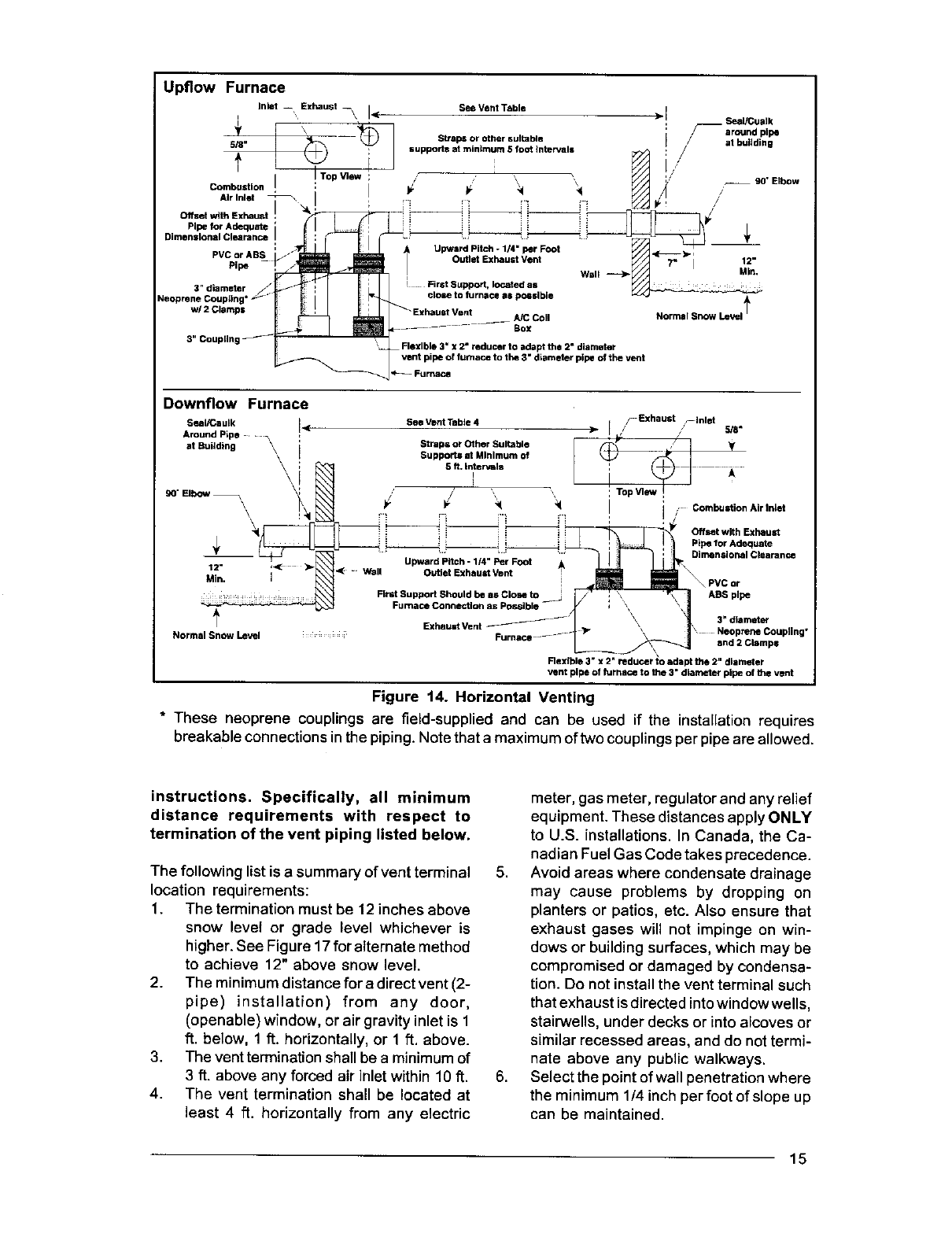
Upflow Furnace
Inlot -- Exhaust _\ I See Vent Table !
.(
I
=Seal/Cualk
*'_ __ _ :/_aroundpips
5/8"
I
I
Combustion
Air Inlet 7\ I
OtfsetwithExhau ! _
Pips for Adequate '
PVC or ABS ' -J
Neopren3e "_apl_nt_ r _ ' [
Straps or other suitable /at buildin
supports at minimum 5foot intervals _ ! /g
; o=,=E,ha°atVent 1="
| Wall _Y_._ MIn,
!
Exhaust Vent A/C Coil Normal Snow Level _
_,---- - "------ Box
'Flexible 3" x2= reducer to adapt the 2" diameter
vent pips of furnace to the 3" diameter pipe of the vent
--Fuma_
Downflow Furnace
SealiCautk I<
Around Pipe
atSu.dth0 \\ I
\
Min, i
Normal Snow Level
See Vent Table 4
Straps or Other Suitable
Supports at Minimum of
5 fL intervals
Upward Pitch - 1/4" Per Foot •
Wall Outlet Exhaust Vent
First Support Should he as Close to
Fumace ConnecUon as Possible --
Exhauat Vent
/Exhaust _lnlat
[/// 5/8"
Ii *
: Top View !
rrCombustion Air In_'t
Offset with Exhaust
Pipe for Adequate
Dimensioi_al Clearance
PVC or
ASS pipe
3" diamat_
Neoprene Coupling"
and 2 Clamps
Rax{b •3" x2 reducer to adapt the 2" diameter
vent pipe of furnace to the 3" dLameter pipe of the vent
Figure 14. Horizontal Venting
* These neoprene couplings are field-supplied and can be used if the installation requires
breakable connections inthe piping. Note that a maximum of two couplings per pipe are allowed.
instructions. Specifically, all minimum
distance requirements with respect to
termination of the vent piping listed below.
The following list is a summary of vent terminal
location requirements:
1. The termination must be 12 inches above
snow level or grade level whichever is
higher. See Figure 17 for alternate method
to achieve 12" above snow level.
2. The minimum distance for adirect vent (2-
pipe) installation) from any door,
(openable) window, or air gravity inlet is 1
ft. below, 1 It. horizontally, or 1 ft. above.
3. The vent termination shall be a minimum of
3 ft. above any forced air inlet within 10 ft.
4. The vent termination shall be located at
least 4 ft. horizontally from any electric
meter, gas meter, regulator and any relief
equipment. These distances apply ONLY
to U.S. installations. In Canada, the Ca-
nadian Fuel Gas Code takes precedence.
5. Avoid areas where condensate drainage
may cause problems by dropping on
planters or patios, etc. Also ensure that
exhaust gases will not impinge on win-
dows or building surfaces, which may be
compromised or damaged by condensa-
tion. Do not install the vent terminal such
that exhaust is directed into window wells,
stairwells, under decks or into alcoves or
similar recessed areas, and do not termi-
nate above any public walkways.
6. Select the point of wall penetration where
the minimum 1/4 inch per foot of slope up
can be maintained.
15

Upfiow Furnace
Rubber
Couplinl
Combustion
Air Pipe
3" Coupling
Furnace Front
Box
Fumace \
Support System
on VertJc_atRise
blow Joints
Support System wKh flmt support
as clolm to the furnace as posslbJe
114" per foot
3" diameter
Neoprene Coupling*
w/2 Clamps
Downflow Furnace
C
Exhaust
Support System
on Vertical Rise
Below Joints
Support System with flint support
as close to the furnace as possible
Upwa_ Pitch
l_'_rFoot
Flexible 3" x2" neducRr
to adapt tha 2" diameter
vent pipe of furnace to
the 3" diameter pipe of
the vent
Figure 15. Vertical Venting
Upflow Furnace Downflow Furnace
Combustion Air Inlet Pipe Collar
Diameter 3" for coupling or reducer
Fureace Top _
2" PVC Exhaust Vent All Models
Combustion Air Inlet
3" PVC on 0801t00 models
Furnace Top
_2" PVC
Exhaust Vent
All Models
Useappropriateadaptorforconnectiontofurnace. Useappropriateadaptorforconnection to furnace.
Figure 16. Furnace Pipe Adaptions
16
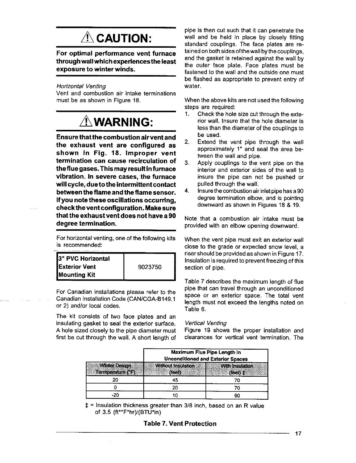
CAUTION:
For optimal performance vent furnace
through wall which experiences the least
exposure to winter winds.
Horizontal Venting
Vent and combustion air intake terminations
must be as shown in Figure 18.
, WARNING:
Ensure thatthe combustion airvent and
the exhaust vent are configured as
shown in Fig. 18. Improper vent
termination can cause recirculation of
the flue gases. This may result in furnace
vibration. In severe cases, the furnace
will cycle, due to the intermittent contact
between the flame and the flame sensor.
If you note these oscillations occurring,
check the vent config u ration. Make sure
that the exhaust vent does not have a 90
degree termination.
pipe is then cut such that it can penetrate the
wall and be held in place by closely fitting
standard couplings. The face plates are re-
tained on both sides ofthewall bythe couplings,
end the gasket is retained against the wall by
the outer face plate. Face plates must be
fastened to the wall and the outside one must
be flashed as appropriate to prevent entry of
water.
When the above kits are not used the following
steps are required:
1. Check the hole size cut through the exte-
rior wall. Insure that the hole diameter is
less than the diameter of the couplings to
be used.
2. Extend the vent pipe through the wall
approximately 1" and seal the area be-
tween the wall and pipe.
3. Apply couplings to the vent pipe on the
interior and exterior sides of the wall to
insure the pipe can not be pushed or
pulled through the wall.
4. Insure the combustion air inlet pipe has a 90
degree termination elbow, and is pointing
downward as shown in Figures 18 & 19.
Note that a combustion air intake must be
provided with an elbow opening downward.
For horizontal venting, one of the following kits
is recommended:
J .. vc.or,zono,J J
Exterior Vent 9023750
Mounting Kit
For Canadian installations please refer to the
Canadian Installation Code (CAN/CGA-B149.1
or 2) and/or local codes.
The kit consists of two face plates and an
insulating gasket to seal the exterior surface.
A hole sized closely to the pipe diameter must
first be cut through the wall. A short length of
When the vent pipe must exit an exterior wall
close to the grade or expected snow level, a
riser should be provided as shown in Figure 17.
Insulation is required to prevent freezing of this
section of pipe.
Table 7 describes the maximum length of flue
pipe that can travel through an unconditioned
space or an exterior space. The total vent
length must not exceed the lengths noted on
Table 6.
Vertical Venting
Figure 19 shows the proper installation and
clearances for vertical vent termination. The
Maximum Flue Pipe Length in
Unconditioned and Exterior Spaces
20 45 7O
020 70
-20 10 60
_: = Insulation thickness greater than 3/8 inch, based on an R value
of 3.5 (ft*°F*hr)/(BTU*in)
Table 7. Vent Protection
17

VentConfigurationto
Provide12"Minimum
height above
Snow LeveE. _. 12" Min,
19" Max.
Out,ide Su po.
wa,, •
_1/2"
_Armaflex
i _ Insulationor
Equivalent
-- 12" Above
Normally
Expected
Snow
Level
ExhaustVent
Op_on B _
Figure 17. Alternate Horizontal
Vent Installation
roof penetration must be properly flashed and
waterproofed witha plumbing roof boot or equiva-
lent flashing. Termination spacing requirements
from the roof and from each other must be per
Figure 19.
Figure 18. Exhaust and Combustion
Air Pipe Clearances
below freezing, i.e., installation within a pre-
existing masonry chimney; the pipe must be
insulated with 1/2 inch thick sponge rubber
insulation, such as an Armaflex-type or equiva-
lent.
Vent and combustion air piping may be in-
stalled in an existing chimney which is not in
use provided that:
a. Both the exhaust vent and air intake run
the length of the chimney.
b. The top of the chimney is sealed and
weatherproofed.
c. The termination clearances shown in
Figure 19 are maintained.
d. No other gas fired appliances are vented
through the chimney.
Vent Freezing Protection
To prevent condensate icing over extended
runs of vent pipe exposed to temperatures
Exhaust
; Vent's.
Combustion
Air
Exhaust
Plumbing Vent
Roof Boot
('ryp, Both Pipes)
iA= 12"AboveRooforSnowAccumulationLevel
Figure t9. Vertical Vent Termination
For extremely cold climates or for conditions of
short furnace cycles (i.e. set back thermostat
conditions) the last three feet of vent pipe can
be reduced one nominal pipe size provided that
the total vent length is at least 15 feet in length
and the vent is sized in accordance with the
venting requirements (Table 4) before this re-
duction isapplied. (Example: 3"to2-1/2") Smaller
vent pipes are less susceptible to freezing, but
must not be excessively restrictive.
Concentric Vent Termination
A concentric vent termination is approved for
use with these furnaces. The kit part number is
listed in Table 13. For proper installation of the
concentric vent termination, follow the installa-
tion instructions provided with that kit.
DRAINAGE OF CONDENSATE FROM
FURNACE
/ WARNING:
The condensate produced by the fumace
m ust be drained. Do not connect a water
supply to the drainage hose of the
furnace.
NOTE: The condensate drain should be pro-
tected from freezing when in unheated spaces.
18
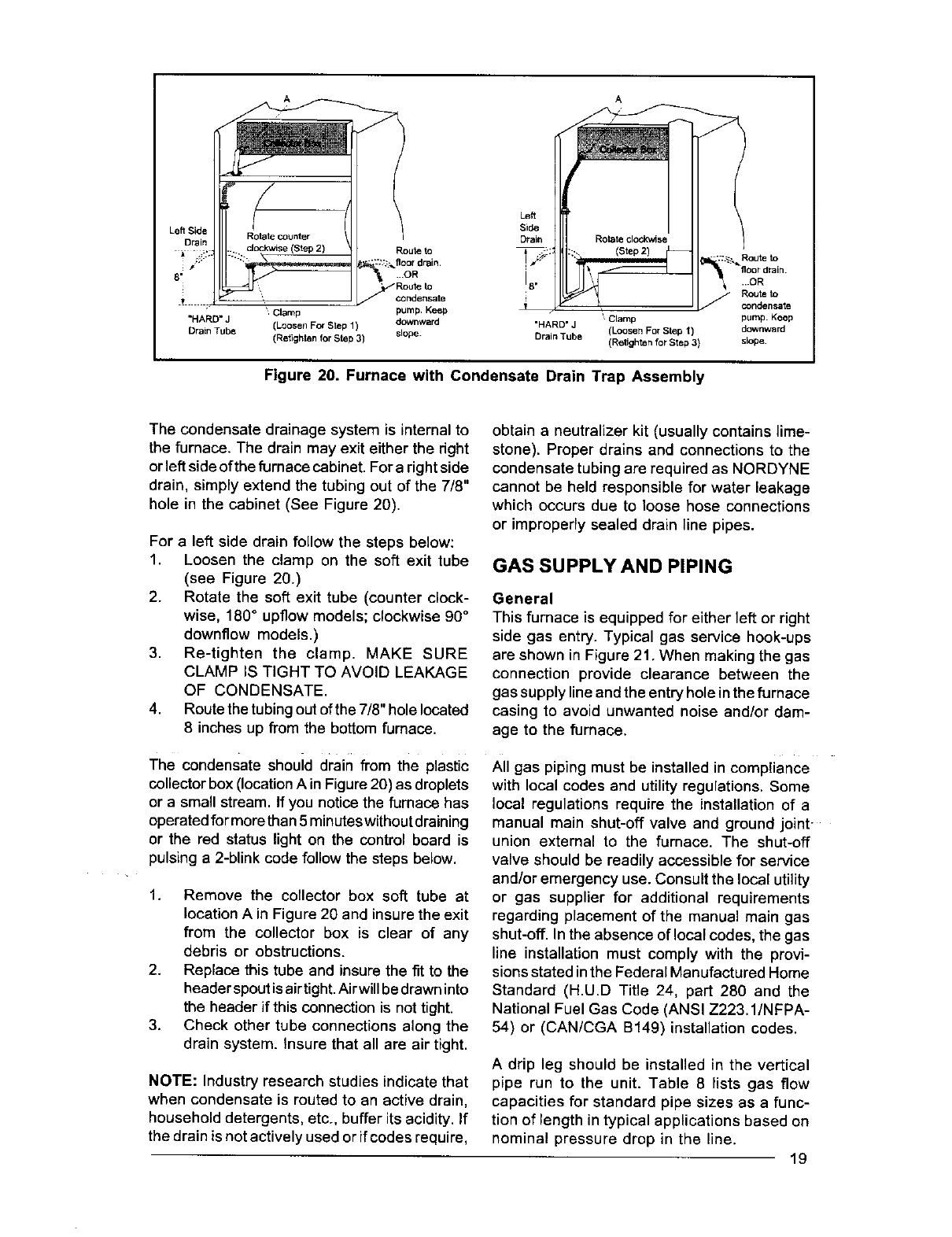
"HARD" J
Drain Tube
Left
Side
Drain
Route to
floordrain. I Routeto
Im mOR
18.... OR
, Route Io
condensate _ condel_sate
Clamp pump. Ksep _ Clamp pump¸ Keop
(LoosenForStepI) downward "HARD' J (LoosenForSlepI) downward
(RetightanforStep 3) slope. Drain Tube (R(_tightenforStep 3) slope.
Figure 20. Furnace with Condensate Drain Trap Assembly
The condensate drainage system is internal to
the furnace. The drain may exit either the dght
or left side of the furnace cabinet. For a right side
drain, simply extend the tubing out of the 7/8"
hole in the cabinet (See Figure 20).
For a left side drain follow the steps below:
1. Loosen the clamp on the soft exit tube
(see Figure 20.)
2. Rotate the soft exit tube (counter clock-
wise, 180° upflow models; clockwise 90 °
downflow models.)
3. Re-tighten the clamp. MAKE SURE
CLAMP IS TIGHT TO AVOID LEAKAGE
OF CONDENSATE.
4. Route the tubingout ofthe 7/8"hole located
8 inches up fl'om the bottom furnace.
The condensate shouid drain from the plastic
collector box (location A in Figure 20) as droplets
or a small stream. If you notice the furnace has
operated formorethan 5minutes without draining
or the red status light on the control board is
pulsing a 2-blink code follow the steps below.
1. Remove the collector box soft tube at
location A in Figure 20 and insure the exit
from the collector box is clear of any
debris or obstructions.
2. Replace this tube and insure the fit to the
header spout is airtight. Airwill be drawn into
the header if this connection is not tight.
3. Check other tube connections along the
drain system. Insure that all are air tight.
NOTE: Industry research studies indicate that
when condensate is routed to an active drain,
household detergents, etc., buffer its acidity. If
the drain is not actively used or if codes require,
obtain a neutralizer kit (usually contains lime-
stone). Proper drains and connections to the
condensate tubing are required as NORDYNE
cannot be held responsible for water leakage
which occurs due to loose hose connections
or improperly sealed drain line pipes.
GAS SUPPLY AND PIPING
General
This furnace is equipped for either left or right
side gas entry. Typical gas service hook-ups
are shown in Figure 21. When making the gas
connection provide clearance between the
gas supply line and the entryhole inthe furnace
casing to avoid unwanted noise and/or dam-
age to the furnace.
All gas piping must be installed in compliance
with local codes and utility regulations. Some
local regulations require the installation of a
manual main shut-off valve and ground joint-
union external to the furnace. The shut-off
valve should be readily accessible for service
and/or emergency use. Consult the local utility
or gas supplier for additional requirements
regarding placement of the manual main gas
shut-off. In the absence of local codes, the gas
line installation must comply with the provi-
sions stated inthe Federal Manufactured Home
Standard (H.UD Title 24, part 280 and the
National Fuel Gas Code (ANSI Z223.1/NFPA-
54) or (CAN/CGA B149) installation codes.
A drip leg should be installed in the vertical
pipe run to the unit. Table 8 lists gas flow
capacities for standard pipe sizes as a func-
tion of length in typical applications based on
nominal pressure drop in the line.
19
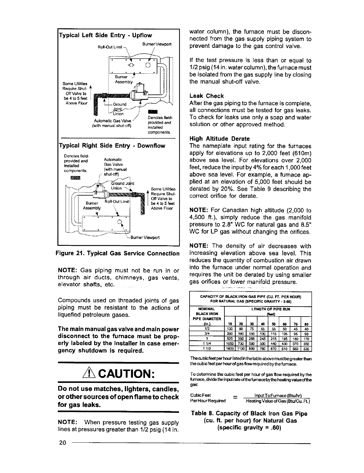
Typical Left Side Entry -Upflow
Burner Viewport
Roll_ut Limit
°Ourn r °'llll
Some Utilities Assembly
Require Shut- I F _
Off Valve to
be 4 to 5 feet
Above Floor - Ground
/Denotes field-
Automatic Gas Valve /provided and
(wdh manuel shut-off) installed
component.
Typical Right Side Entry -Downflow
Denotes field-
provided and Automatic
installed Gas Valve
components. (with manual
shut-off)
'Ground J<
, UrlioR
Burner Roll-Out Lim_
Assembly _,
Ii .....
int
Some Utilities
1Require Shut-
Off Valve to
be 4 to 5feet
Above Floor
_-Bumer Viewport
Figure 21. Typical Gas Service Connection
NOTE: Gas piping must not be run in or
through air ducts, chimneys, gas vents,
elevator shafts, etc.
water column), the furnace must be discon-
nected from the gas supply piping system to
prevent damage to the gas control valve.
If the test pressure is less than or equal to
1/2 psig (14 in. water column), the furnace must
be isolated from the gas supply line by closing
the manual shut-off valve.
Leak Check
After the gas piping to the furnace is complete,
all connections must be tested for gas leaks.
To check for leaks use only a soap and water
solution or other approved method.
High Altitude Derate
The nameplate input rating for the furnaces
apply for elevations up to 2,000 feet (610m)
above sea level. For elevations over 2,000
feet, reduce the input by 4% for each 1,000 feet
above sea level. For example, a furnace ap-
plied at an elevation of 5,000 feet should be
derated by 20%. See Table 9 describing the
correct orifice for derate.
NOTE: For Canadian high altitude (2,000 to
4,500 ft.), simply reduce the gas manifold
pressure to 2.8" WC for natural gas and 8.5"
WC for LP gas without changing the orifices.
NOTE: The density of air decreases with
increasing elevation above sea level. This
reduces the quantity of combustion air drawn
into the furnace under normal operation and
requires the unit be derated by using smaller
gas orifices or lower manifold pressure.
Compounds used on threaded joints of gas
piping must be resistant to the actions of
liquefied petroleum gases.
The main manual gas valve and main power
disconnect to the furnace must be prop-
erly labeled by the installer in case emer-
gency shutdown is required.
CAUTION:
Do not use matches, lighters, candles,
or other sources of open flame to check
for gas leaks.
NOTE: When pressure testing gas supply
lines at pressures greater than 1/2 psig (14 in.
CAPACITY OF BLACK IRON GAS PIPE (CU, FT, PER HOUR)
FOR NATURAL GAS (SPECIFIC GRAVITY - 0.60)
i_OMI MAL LENGTH OF PIPE RUN
BLACK IRON _feet)
PIPE DIAMETER
(in. I10 2D 30 40 50 60 70 80
1/2 130 90 75 65 55 50 45 40
3#4 280 190 150 130 115 105 95 90
1520 350 285 245 215 195 180 170
1114 1050 730 590 5(0 440 400 370 350
1 1/2 1600 1100 890 7_ 670 610 560 530
T_ecubicfeetperhourlietedinthetableabovemustbegreeterthan
thecubicfeetperhourofgasflowrequiredbythefurnace.
To determine the cubic feet per hour of gas flow required by the
furnace, divide the input rate ofthe furnace bythe heating value ofthe
gas:
Cubic Feet -- InputTo Furnace (Btu/hr)
PerHourRequired HeatingValue ofGas (Btu/Cu, Ft.)
Table 8. Capacity of Black Iron Gas Pipe
(cu. ft. per hour) for Natural Gas
(specific gravity = .60)
2O
CONVERSION
This furnace can be converted from the factory-
equipped gas to either natural gas (for LP gas
ready models), or LP gas (for natural gas ready
models). Conversions must be made by quali-
filed service personnel, using only factory autho-
dzed or approved parts. The required conver-
sion orifices are supplied with the furnace.
/ WARNING:
DO NOT REMOVE OR DEFACE THE
ORIGINAL RATING PLATE.
CAUTION:
The gas supply shall be shut off prior to
disconnecting the electrical power,
before proceeding with the conversion.
To Turn Off Fuel Supply to the Appliance:
1. Set the room thermostat to "OFF" or its
lowest temperature setting.
2. Turn OFF the main gas supply to the
appliance at the manual valve, outside of
the appliance casing.
3. Remove the control access panel /Iou-
vered door.
4. Move the appliance gas valve lever/knob
to the "OFF" position.
5. Turn OFF the electrical power to the
appliance.
To Remove the Burner Assembly:
1. Follow the instructions "To Turn Off the
Fuel Supply to the Appliance."
2. Disconnect the flame sensor wire from
the burner box.
3. Disconnect the igniter wires at the 2 pin
plug. This is a locking quick connect and
both sides of the lower section must be
depressed in order to be separated.
4. Remove the wires from the terminals of
the gas valve.
5. Disconnect the rubber pressure tubes
from the gas valve and the burner box.
6. Remove the burner access cover plate
from the burner box.
7. Remove supply gas piping from the gas
valve.
8. Carefully remove the burner assembly fas-
teners and remove the bumer assembly from
the appliance. Keep the fasteners that were
removed. Note that the burner box may have
hooks near the top and on the right and left
hand sides. To remove this type of bumer
box, lift the burner box upwards and then
remove the box from the unit.
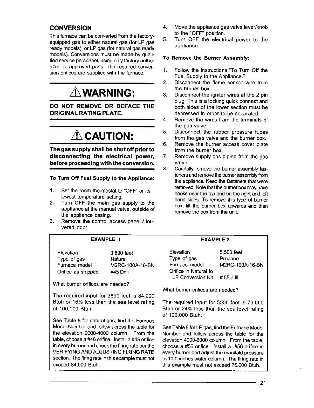
EXAMPLE 1 EXAMPLE 2
Elevation
Type of gas
Furnace model
Odfice as shipped
3,890 feet
Natural
M2RC-100A-16-BN
#45 Ddll
What burner odfices are needed?
The required input for 3890 feet is 84,000
Btuh or 16% less than the sea level rating
of 100,000 Btuh.
See Table 8 for natural gas, find the Furnace
Model Number and follow across the table for
the elevation 2000-4000 column. From the
table, choose a#46 orifice. Install a #46 orifice
in every burner and check the fidng rate per the
VERIFYING AND ADJUSTING FIRING RATE
section. The fidng rate in this example must not
exceed 84,000 Btuh.
Elevation
Type of gas
Furnace model
Orifice in Natural to
LP Conversion Kit
5,500 feet
Propane
M2RC-100A-16-BN
# 55 drill
What burner odfices are needed?
The required input for 5500 feet is 76,000
Btuh or 24% less than the sea level rating
of 100,000 Btuh.
See Table 8 for LP gas, find the Furnace Model
Number and follow across the table for the
elevation 4000-6000 column. From the table,
choose a #56 orifice, install a #56 odfice in
every burner and adjust the manifold pressure
to 10.0 inches water column. The fidng rate in
this example must not exceed 76,000 Btuh.
21
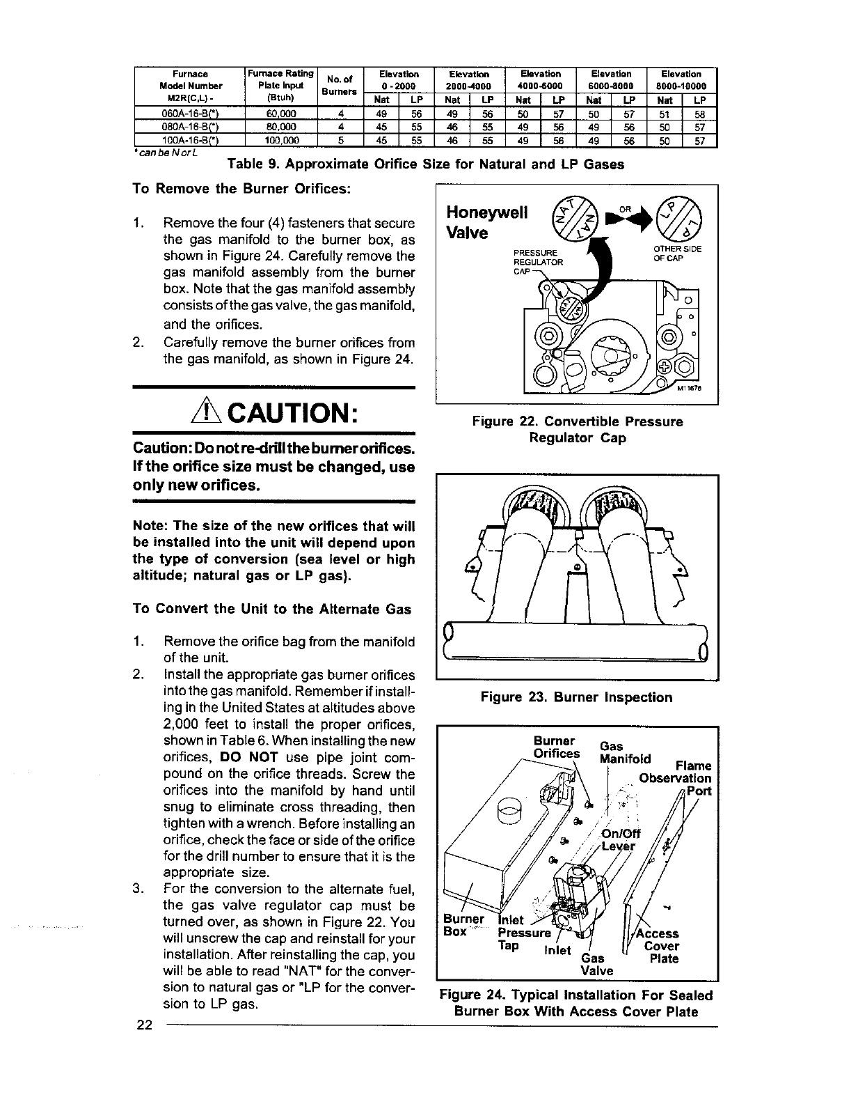
Furnace Furnace Rating No. of Elevation Elevation Elevation Elevation Elevation
Model Number Plate Input Burners 0 - 2000 2000-4000 4000-6000 6000-6000 8000-10000
M2R(C,L) - (Btuh) Nat LP Nat LP Nat LP Nat LP Nat LP
060A-16-B(* I60tO00 449 56 49 56 50 57 50 57 51 58
080A-16-B(*) 80,000 445 55 46 55 49 56 49 56 50 57
100A-16-B(*) 100,000 5 45 55 46 55 49 56 49 56 50 57
*canbeNorL Table 9. Approximate Orifice Size for Natural and LP Gases
To Remove the Burner Orifices:
1. Remove the four (4) fasteners that secure
the gas manifold to the burner box, as
shown in Figure 24. Carefully remove the
gas manifold assembly from the burner
box. Note that the gas manifold assembly
consists of the gas valve, the gas manifold,
and the orifices.
2. Carefully remove the burner orifices from
the gas manifold, as shown in Figure 24.
Honeywell
Valve
PRESSURE
REGULATOR
OTHER SIDE
OF CAP
CAUTION:
Caution: Do not re-drill the burner odfices.
If the orifice size must be changed, use
only new orifices.
Note: The size of the new orifices that will
be installed into the unit will depend upon
the type of conversion (sea level or high
altitude; natural gas or LP gas),
To Convert the Unit to the Alternate Gas
1. Remove the orifice bag from the manifold
of the unit.
2. Install the appropriate gas burner orifices
into the gas manifold. Remember if install-
ing in the United States at altitudes above
2,000 feet to install the proper orifices,
shown in Table 6. When installing the new
orifices, DO NOT use pipe joint com-
pound on the orifice threads. Screw the
orifices into the manifold by hand until
snug to eliminate cross threading, then
tighten with a wrench. Before installing an
orifice, check the face or side of the orifice
for the drill number to ensure that it is the
appropriate size.
3. For the conversion to the alternate fuel,
the gas valve regulator cap must be
turned over, as shown in Figure 22. You
will unscrew the cap and reinstall for your
installation. After reinstalling the cap, you
will be able to read "NAT" for the conver-
sion to natural gas or "LP for the conver-
sion to LP gas.
Figure 22. Convertible Pressure
Regulator Cap
Figure 23. Burner Inspection
Burner Gas
Orifices Manifold Flame
_t ,_;f_iObservatiOn
Inlet
,Cover
Tap Inlet Gas Plate
Valve
Figure 24. Typical Installation For Sealed
Burner Box With Access Cover Plate
22
Reinstallingthe Burner Assembly:
1. Reinstall the gas manifold assembly to
the burner box with the four (4) fasteners,
which were removed earlier.
2. Carefully reinstall the burner box into the
unit. After installing the burner, inspect
the alignment of the burners with the heat
exchanger tubes. The center of the burn-
ers should be aligned with the center of
the tubes.
3. Reconnect the gas piping to the gas
valve.
4. Reconnect the wires to the gas valve
terminals.
5. Reconnect the rubber pressure tubes to
the gas valve and the burner box. Rein-
stall the burner access cover plate.
6. Reconnect the igniter at the 2 position
plug.
7. Reconnect the flame sensor wire to the
burner box.
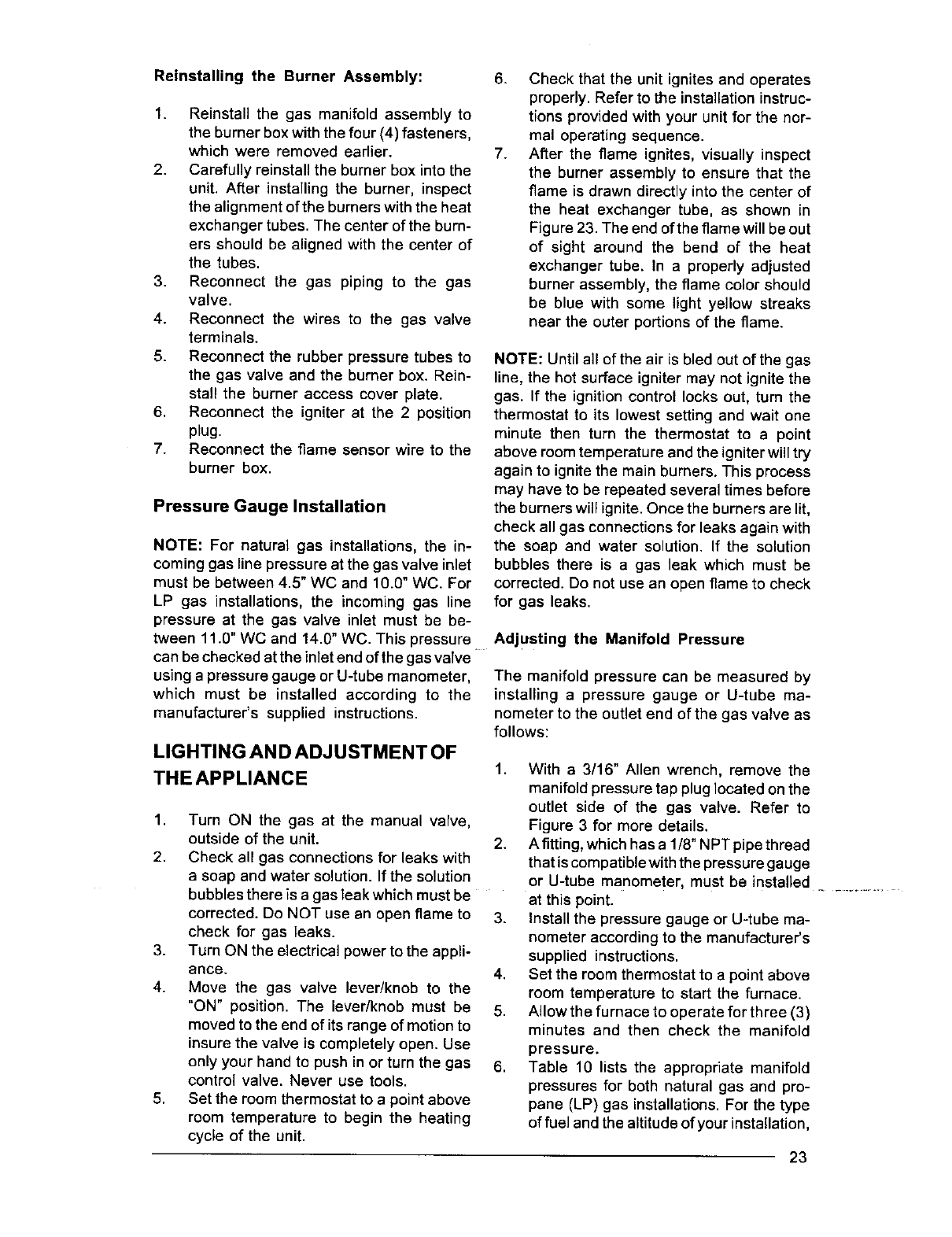
Pressure Gauge Installation
NOTE: For natural gas installations, the in-
coming gas line pressure at the gas valve inlet
must be between 4.5" WC and 10.0" WC. For
LP gas installations, the incoming gas line
pressure at the gas valve inlet must be be-
tween 11.O"WC and 14.0" WC. This pressure
can be checked at the inlet end of the gas valve
using a pressure gauge or U-tube manometer,
which must be installed according to the
manufacturer's supplied instructions.
LIGHTING AND ADJUSTMENT OF
THE APPLIANCE
1. Turn ON the gas at the manual valve,
outside of the unit.
2. Check all gas connections for leaks with
a soap and water solution. If the solution
bubbles there is a gas leak which must be
corrected. Do NOT use an open flame to
check for gas leaks.
3. Turn ON the electrical power to the appli-
ance.
4. Move the gas valve lever/knob to the
"ON" position. The lever/knob must be
moved to the end of its range of motion to
insure the valve is completely open. Use
only your hand to push in or turn the gas
control valve. Never use tools.
5. Set the room thermostat to apoint above
room temperature to begin the heating
cycle of the unit.
.
7.
Check that the unit ignites and operates
properly. Refer to the installation instruc-
tions provided with your unit for the nor-
mal operating sequence.
After the flame ignites, visually inspect
the burner assembly to ensure that the
flame is drawn directly into the center of
the heat exchanger tube, as shown in
Figure 23. The end of the flame will be out
of sight around the bend of the heat
exchanger tube. In a properly adjusted
burner assembly, the flame color should
be blue with some light yellow streaks
near the outer portions of the flame.
NOTE: Until all of the air is bled out of the gas
line, the hot surface igniter may not ignite the
gas. If the ignition control locks out, turn the
thermostat to its lowest setting and wait one
minute then turn the thermostat to a point
above room temperature and the igniter will try
again to ignite the main burners. This process
may have to be repeated several times before
the burners will ignite. Once the burners are lit,
check all gas connections for leaks again with
the soap and water solution. If the solution
bubbles there is a gas leak which must be
corrected. Do not use an open flame to check
for gas leaks.
Adjusting the Manifold Pressure
The manifold pressure can be measured by
installing a pressure gauge or U-tube ma-
nometer to the outlet end of the gas valve as
follows:
1. With a 3/16" Allen wrench, remove the
manifold pressure tap plug located on the
outlet side of the gas valve. Refer to
Figure 3 for more details.
2. A fitting, which has a 1/8" NPT pipe thread
that is compatible with the pressure gauge
or U-tube manometer, must be installed ............
at this point.
3. Install the pressure gauge or U-tube ma-
nometer according to the manufacturer's
supplied instructions.
4. Set the room thermostat to a point above
room temperature to start the furnace.
5. Allow the furnace to operate for three (3)
minutes and then check the manifold
6. pressure.
Table 10 lists the appropriate manifold
pressures for both natural gas and pro-
pane (LP) gas installations, For the type
of fuel and the altitude of your installation,
23
Natural Propane
Gas (LP)
Manifold Pressure for 0-2000 3.5 10.0
Feet Above Sea Level (In WC)
Table 10. Manifold Pressures for Sea Level
determine the required manifold pres-
sure. For Canadian high altitude installa-
tions, refer to the "High Altitude Derate"
section for more details.
COMPLETING THE CONVERSION
1. Affix the gas valve conversion label found
in the package with the orifices to the unit
rating plate.
2. Run the appliance through a complete
cycle to assure proper operation.
CAUTION:
To avoid electric shock, personal
injury, or death, turn offthe power at
the disconnect or the main service
panel before making any electrical
connections.
ELECTRICAL WIRING
General
Electrical connections must be made in accor-
dance with all applicable local codes and ordi-
nances, and with the current revision of the
National Electric Code (ANSI/NFPA 70).
For Canadian installations electrical connec-
tions and grounding must be done in accor-
dance with the current Canadian Electrical
Code (CSA C22.1 Part 1) and/or local codes.
If any of the odginal wire as supplied with the
furnace must be replaced, it must be replaced
with wire having a minimum temperature rating
of 105°C. Refer to the furnace nameplate and
Table 8 for electrical requirements.
Line Voltage Wiring
The line voltage (115 volt) to the furnace must
be supplied from a dedicated branch circuit
containing the correct fuse or circuit breaker
for the furnace. See Table 11. An electrical
switch should be readily accessible from and
within sight of the furnace. See the Wiring
Diagram label in the furnace for more details.
The furnace cabinet must have an uninter-
rupted, unbroken ground to minimize injury
should an electrical fault condition occur. The
controls used in this furnace require an earth
ground to operate properly. Acceptable meth-
ods for grounding are electrical wire or conduit
approved for electrical ground service. Do not
use gas piping as an electrical ground.
i
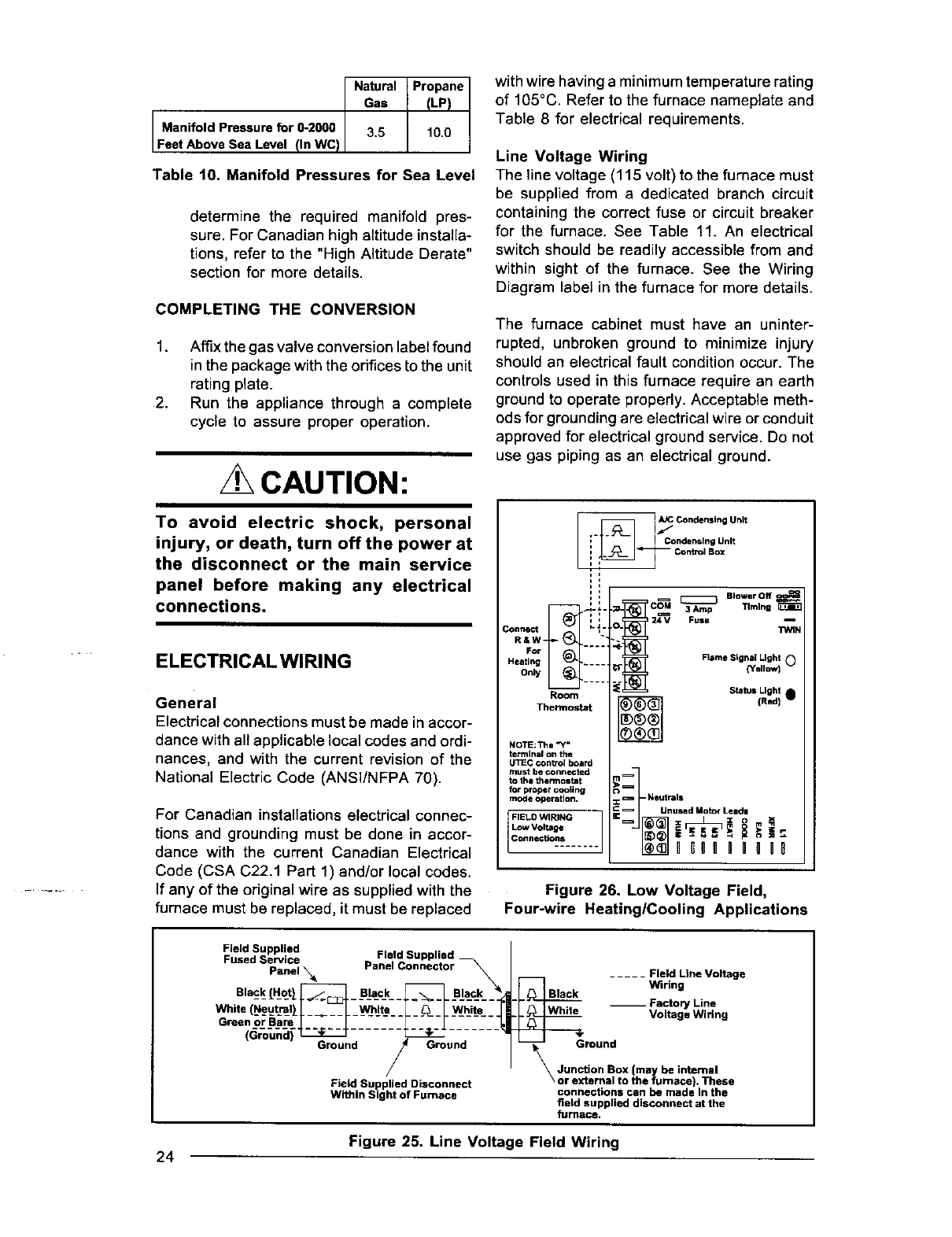
R&W ""
For .....
Heating .....
Only .....
Room
Thermostat
NOTE:Ttla "_
terminal on the
UTiEC control board
must be connected
to the thermostat
for proper cooling
mode _atlon.
FIELD WIRING
Low Voltage
Connections
A_ Condensing Unit
,,/
Condensing Unit
-- Control Box
[_ Blower Off
3Amp Tlmlng
Fuse T_N
Flame Signal Light
{Yell_ i 0
Status Light
{R,dI •
i
:_=Neutrals
_Unused Motor Leads
Figure 26. Low Voltage Field,
Four-wire Heating/Cooling Applications
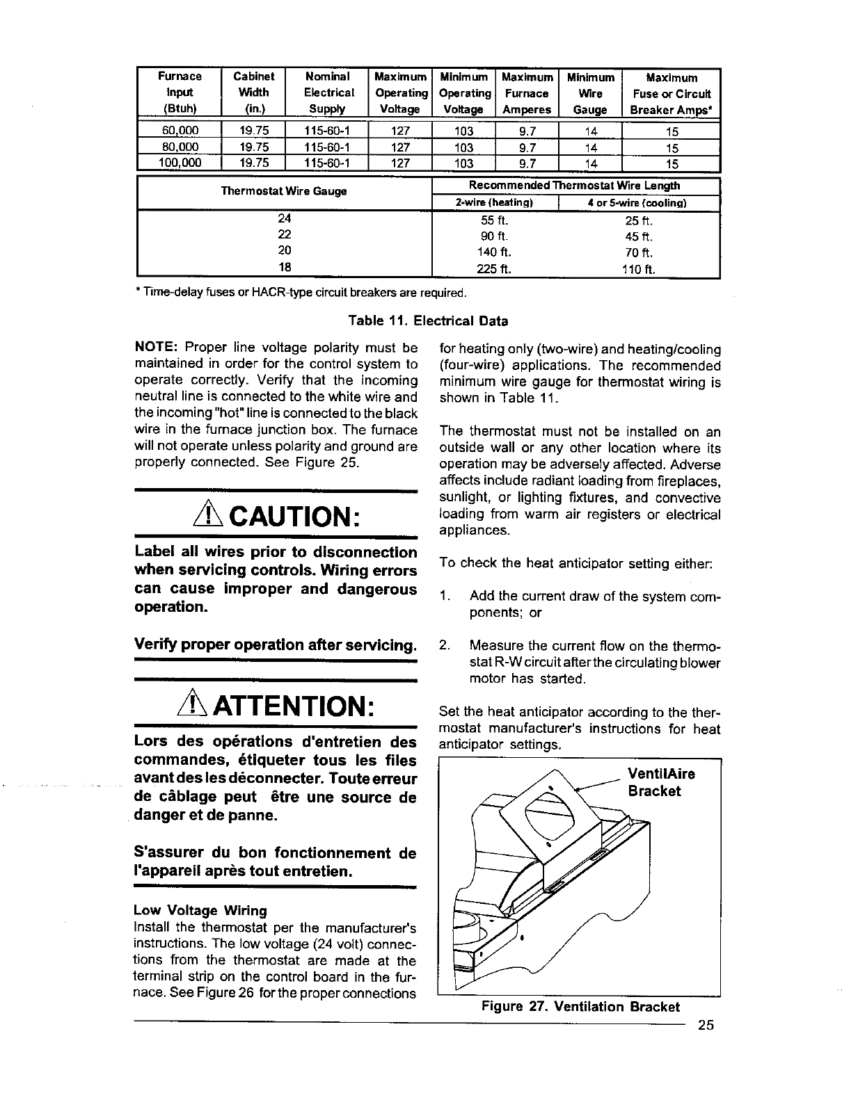
F_/ddS_P pwliied Field Supplied
Panel _Panel Connector
Black_H_ot)J_] Black _Black
ite (Neut-_l_ ____ ___ -_/-hit-e- -______ _-_ _/hite- -
(Ground) _
Ground /Ground
Field Supplied Disconnect
Within Sight of Furnace
..... Field Une Voltage
Black Wiring
Factory Line
White -- Voltage Wiring
round
_Junction Box (may be internal
or external to the furnace). These
connections can be made in the
field supplied disconnect at the
furllace.
Figure 25. Line Voltage Field Wiring
24
Furnace
Input
(Btuh)
60,000
80,000
100,000
Cabinet Nominal
Width Electrical
(in,) Supply
19.75 115-60-1
19.75 115-60-1
19,75 115-60-1
Maximum
Operating
Voltage
127
127
127
Minimum
Operating
Voltage
103
103
103
Maximum Minimum Maximum
Furnace Wire Fuse or Circuit
Amperes Gauge Breaker Amp_*
9.7 14 15
9.7 14 15
9.7 14 15
Thermostat Wire Gauge Recommended Thermostat Wire Length
2-wire {heating) 4 or 5-wire {cooling)
24 55 ft. 25 ft.
22 90 ft. 45 ft,
20 140ft. 70 ft.
18 225 ft, 110ft.
* Time-delayfuses orHACR-typecircuitbreakersare required.
Table 11. Electrical Data
NOTE: Proper line voltage polarity must be
maintained in order for the control system to
operate correctly. Verify that the incoming
neutral line is connected to the white wire and
the incoming "hot" line is connected to the black
wire in the furnace junction box. The furnace
will not operate unless polarity and ground are
properly connected. See Figure 25.
CAUTION:
Label all wires prior to disconnection
when servicing controls. Wiring errors
can cause improper and dangerous
operation.
for heating only (two-wire) and heating/cooling
(four-wire) applications. The recommended
minimum wire gauge for thermostat wiring is
shown in Table 11.
The thermostat must not be installed on an
outside wall or any other location where its
operation may be adversely affected. Adverse
affects include radiant loading from fireplaces,
sunlight, or lighting fixtures, and convective
loading from warm air registers or electrical
appliances.
To check the heat anticipator setting either:
1. Add the current draw of the system com-
ponents; or
Verify proper operation after servicing.
ATTENTION:
Lors des op6rations d'entretien des
commandes, 6tiqueter tous les files
avant des les d6connecter. Toute erreur
de c&blage peut 6tre une source de
danger et de panne.
S'assurer du ben foncUonnement de
rappareil apr_s tout entretien.
Low Voltage Wiring
Install the thermostat per the manufacturer's
instructions.The low voltage (24 volt) connec-
tions from the thermostat are made at the
terminal strip on the control board in the fur-
nace. See Figure 26 for the proper connections
2. Measure the current flow on the thermo-
stat R-W circuit after the circulating blower
motor has started.
Set the heat anticipator according to the ther-
mostat manufacturer's instructions for heat
anticipator settings.
VentilAire
Bracket
Figure 27. Ventilation Bracket
25
VENTILATION
Ventilation must be provided for homes built to
HUD Manufactured Homes Safety and Con-
struction Standards. This ventilation can be
supplied by the VentilAire III or VentilAire IV
accessories (see Table 13). Alternate means
to provide the ventilation air must meet the
requirements of all applicable local and federal
codes.
For downfiow models, a bracket is supplied
with the furnaces to allow the use of the VentilAire
III or VentilAire IV accessories. The bracket is
installed on the right hand side at the top of the
cabinet, as shown in Figure 27. The bracket
can be fastened using the self-drilling screws
supplied with the unit.
For upfiow models, the means to provide the
required ventilation must be incorporated into
the upflow furnace base or the return air
ductwork to the furnace.
For installation of the VentilAire III or IV, follow
the instructions provided with the VentilAire kit.
START-UPANDADJUSTMENTS
General
Prior to start-up, verify that:
.The line voltage power leads are securely
connected, that the polarity of the con-
nections is correct, and that the furnace
is properly grounded.
2.
3,
The thermostat wires (R, W, Y, and G) are
securely connected to the correct leads
on the terminal strip of the circuit board.
The natural gas line service pressure must
not exceed 10.0 in. water column (0.36
psig), and must not be less than 4.5 in. water
column (0.16 psig). For LP gas the line
service pressure must not exceed 14 in.
water column (0.51 psig), and must not be
less than 11.0 in. W.C. (0.40 psig).
4,
26
The roll-out and vent safety manual reset
switches are closed. If necessary, press
the red button to reset aswitch. See
Figure 31 for location. DO NOT install a
jumper wire across a switch to defeat its
function. If a switch reopens on start-up,
DO NOT reset the switch without identi-
fying and correcting the fault condition
which caused the switch to trip.
5. The blower door is in place, closing the
door switch in the line voltage circuit.
6. The gas line has been purged and all
connections are leak tight.
Start-Up Procedure
1. Set the thermostat to the lowest setting.
2. Close the disconnect(s) to provide line
voltage to the furnace.
3. Follow the procedures given on the oper-
ating instructions label attached to the
furnace.
4. Set the thermostat above room tempera-
ture and verify the sequence of operation.
(See the SEQUENCE OF OPERATION.)
5, After the furnace has run for approximately
five minutes, set the thermostatbelow room
temperature and verify steps 9 - 11 of the
SEQUENCE OF OPERATION.
Shut Down Procedure
In the event that the furnace must be shut down,
follow this procedure:
1. Set the room thermostat to "OFF" or its
lowest temperature setting.
2.
,
Turn OFF the main gas supply to the
appliance at the manual valve outside of
the appliance casing.
Remove the control access panel /Iou-
vered door.
4. Move the appliance gas valve lever/knob
to the "OFF" position.
5. Turn OFF the electrical power to the
....._lSpli_+n_:e.
Verifying and Adjusting Firing Rate
The firing rate must be verified for each instal-
lation to prevent over-fldng the furnace.
NOTE: The firing rate must not exceed the
rate shown on the furnace rating plate. At
altitudes above 2000 ft. it must not exceed
that on the rating plate less 4% for each
1000 ft.
Use the following procedure to determine the
firing rate:
1. Shut off all other gas fired appliances.
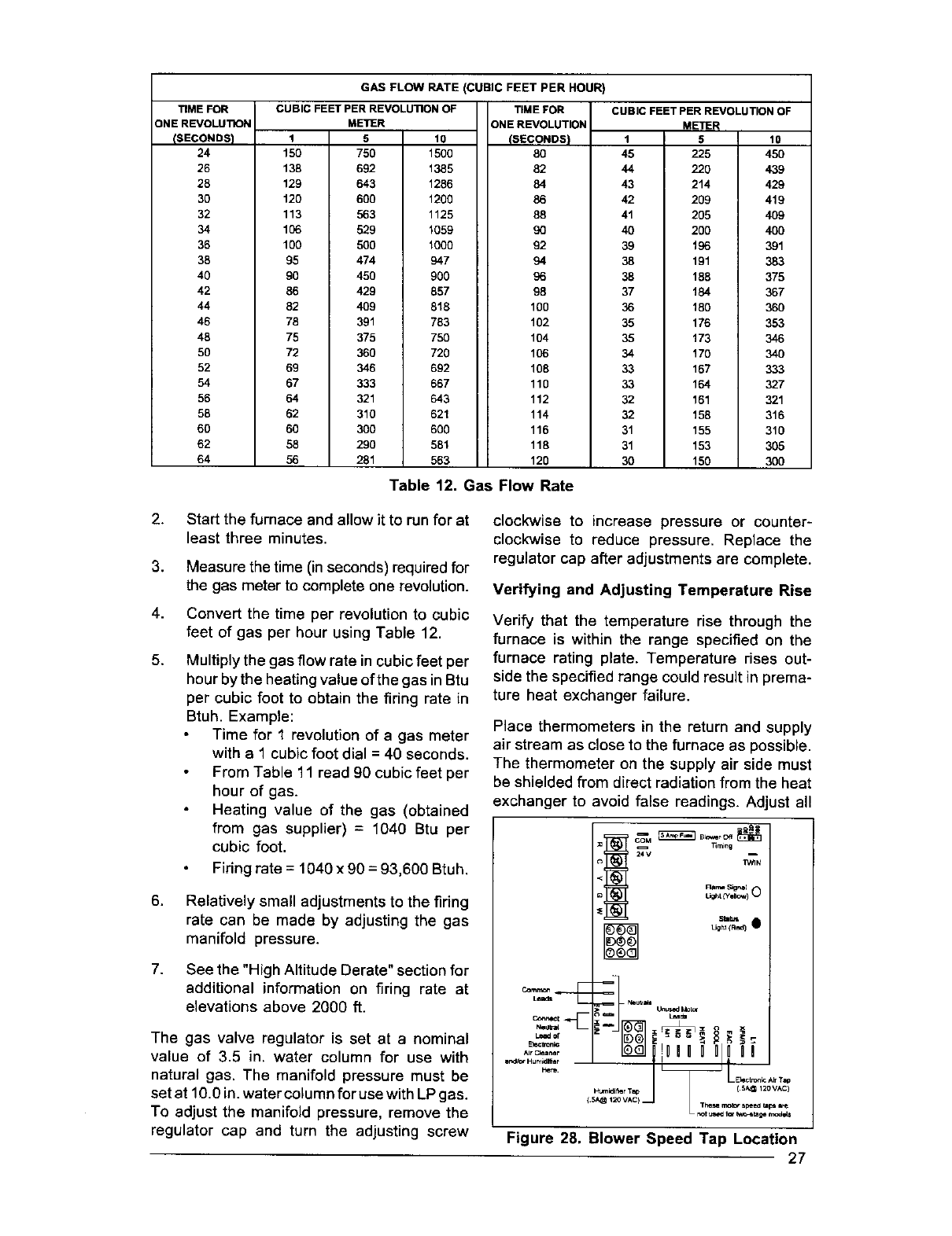
TIME FOR
ONE REVOLUTION
(SECONDS)
24
26
28
30
32
34
36
38
40
42
44
46
48
50
52
54
56
58
60
62
64
GAS FLOW RATE (CUBIC FEET PER HOUR)
CUBIC FEET PER REVOLUTIONOF
METER
1 5 10
150 750 1500
138 692 1385
129 643 1286
120 600 1200
113 563 1125
106 529 1059
100 500 1000
95 474 947
90 450 900
86 429 857
82 409 818
78 391 783
75 375 750
72 360 720
69 346 692
67 333 667
64 321 643
62 310 621
60 300 600
58 290 581
56 281 563
TIME FOR
ONE REVOLUTION
(SECONDS)
80
82
84
86
88
9O
92
94
96
98
100
102
104
106
108
110
112
114
116
118
120
CUBIC FEET PER REVOLUTIONOF
METER
1 5 10
45 225 450
44 220 439
43 214 429
42 209 419
41 205 409
40 200 400
39 196 391
38 191 383
38 188 375
37 184 367
36 180 360
35 176 353
35 173 346
34 170 340
33 167 333
33 164 327
32 161 321
32 158 316
31 155 310
31 153 305
30 150 300
Table 12. Gas Flow Rate
2.
3.
4.
5.
Start the furnace and allow it to run for at
least three minutes.
Measure the time (inseconds) required for
the gas meter to complete one revolution.
Convert the time per revolution to cubic
feet of gas per hour using Table 12.
Multiply the gas flow rate in cubic feet per
hour by the heating value of the gas in Btu
per cubic foot to obtain the firing rate in
Btuh. Example:
Time for 1 revolution of a gas meter
with a 1 cubic foot dial = 40 seconds.
From Table 11 read 90 cubic feet per
hour of gas.
Heating value of the gas (obtained
from gas supplier) = 1040 Btu per
cubic foot.
Firing rate = 1040 x 90 = 93,600 Btuh.
6,
7.
Relatively small adjustments to the firing
rate can be made by adjusting the gas
manifold pressure.
See the "High Altitude Derate" section for
additional information on firing rate at
elevations above 2000 ft.
The gas valve regulator is set at a nominal
value of 3.5 in, water column for use with
natural gas. The manifold pressure must be
set at 10.0 in. water column for use with LP gas.
To adjust the manifold pressure, remove the
regulator cap and turn the adjusting screw
clockwise to increase pressure or counter-
clockwise to reduce pressure. Replace the
regulator cap after adjustments are complete.
Verifying and Adjusting Temperature Rise
Verify that the temperature rise through the
furnace is within the range specified on the
furnace rating plate. Temperature rises out-
side the specified range could result in prema-
ture heat exchanger failure.
Place thermometers in the return and supply
air stream as close to the furnace as possible.
The thermometer on the supply air side must
be shielded from direct radiation from the heat
exchanger to avoid false readings. Adjust all
Timing
24 V I
_N
Ra_ Signal
Cornm_
lead8 NeUVldll UnuoedMOlo_
E_c_cnlc I 4 e- ;=
_._ ..... > _--° ._,_
Figure 28. Blower Speed Tap Location
27
registers and duct dampers to the desired
position and run the furnace for fifteen minutes
before taking any temperature readings. The
temperature rise is the difference between the
supply and return air temperatures.
For typical duct systems, the temperature rise
will fall within the range specified on the rating
plate with the blower speed at the factory
recommended setting. If the temperature rise
measured is outside the range specified, it may
be necessary to change the blower speed.
Lower blower speeds will increase the tem-
perature rise and higher blower speeds will
decrease the temperature rise.
The furnace is equipped with a multispeed
motor. Heating and cooling speed selection is
made by moving the leads on the integrated
control board located in the furnace. The wiring
diagram on the furnace and Figure 28 showthe
speed taps for adjusting motor speed.
If it is desired that the blower operate at the
same speed for heating and cooling, tape off
the terminal of the unused blower wire. Install
the jumper wire, found in the plastic instruction
bag, across the HEAT and COOL taps on the
control board. Reconnect the desired blower
tap to the piggyback quick connect.
The blower control is designed to start the
circulating air blower 30 seconds after the gas
valve is opened. The blower control is factory
wired to turn the blower motor off 120 seconds
after the gas valve is closed. This timing can be
changed using the BLOWER OFF timing switch
opposite the terminal block on the control board
(See Figure 28).
Verifying Burner Operation
To verify operation of the burners, make sure
that the blower compartment door is in place
and that there is power to the furnace. Set the
thermostat above room temperature and ob-
serve the ignition sequence. The flame can be
observed through the small clear window on
the burner box. The burner flame should carry
over between all burners. The flames should
be blue, without yellow tips. Flames should
extend from each burner without lifting, curling,
or floating. After veri_ing ignition, set the ther-
mostat below room temperature and verify that
the burner flame extinguishes completely.
Verifying Operation of the Supply Air
Limit Switch
To verify operation of the supply air limit switch,
make surethatthe blower dooris in place and that
28
there is power to the furnace. Completely block
the retum airflow to the furnace by installinga
close-of[ plate in place of or upstream of the
filter(s). Set the thermostat above room tem-
perature and verify that the Sequence of Opera-
tion is as described in these instructions. The
supply air limit switch should function to turn off
the gas valve within approximately five minutes.
The circulating air and combustion blowers
should continue to run when the supply air limit
switch opens. Remove the close-off plate imme-
diately after the supply air limit switch opens. If
the furnace operates for more than five minutes
with no return air, set the thermostat below room
temperature, shut off the power to the furnace,
and replace the supply air limit switch.
DESCRIPTION OF COMPONENTS
Figure 31 shows the location of each of the
functional components described below. If
any component of the furnace must be re-
placed, use only factory authorized replace-
ment parts. Contact your distributor for the
approved replacement parts.
Flame Sensor - The flame sensor acts to
prove that flame has carried over from the
igniter to the opposite end burner. If no flame
is sensed, the furnace will be shut down
automatically.
Gas Valve - The gas valve controls the flow
of gas to the burners. When the gas valve is
energized it automatically opens and regu-
lates the gas pressure in the manifold.
Pressure Switch - The pressure switch veri-
fies that the inducer is drawing the combustion
gases through the heat exchanger. It also
senses a blocked condensate drain condition.
Vent Pressure Switch (Downflow models
only) - The vent pressure switch reacts to
blockage in the vent or combustion air piping.
Supply Air Limit Switch - The supply air limit
switch prevents the air temperature leaving
the furnace from exceeding the maximum
outlet air temperature.
Vent Safety Switch - The vent safety switch
shuts the furnace down if the outlet flue gas
temperature increases above 160°F, This
switch protects the plastic flue system and the
inducer from over-temperature conditions.
FlameRoll-OutSwitch - This switch pro-
vides flame roll-out protection to the furnace
and combustion air inlet pipe.
MAINTENANCE
It is recommended that the furnace be checked
yearly. At a minimum, this check should include
the following items:
/ WARNING:
To avoid electric shock, personal injury,
or death, turn off the power at the
disconnect or the main service panel
before performing any maintenance.
/ WARNING:
Holes in the vent pipe or heat exchanger
can cause products of combustion to
enter the occupied space. Replace the
vent pipe or heat exchanger if leaks are
found. Failure to prevent products of
combustion from being circulated intothe
occupied space can crate potentially
hazardous conditions, including carbon
monoxide poisoning, that could result in
personal injury or death.
Combustion Air and Vent System
Check the combustion air and vent pipe to
ensure that it is not damaged, corroded or
blocked by debris. Any damaged section of
vent pipe must be replaced, and any obstruc-
tion or blockage must be removed prior to
operating the furnace.
Air Filter(s)
An air filter is supplied with the furnace as
shipped from the factory. Filters should be
changed or cleaned monthly during the heating
season. New or newly renovated homes may
require more frequent changing until the con-
struction dust has been removed.
For the upflow model, the air filter is located
underneath the blower in the blower compart-
ment. To remove the filter, first remove the
lower door. Then, slide the filter backwards until
the edge of the filter clears the front flange of the
furnace. Lift the filter up over the flange and then
remove. Reinstall the filter in the reverse man-
ner. Ensure that the filter is centered over the
return opening of the furnace, and is captured
by the fastener at the rear of the furnace.
For the downflow model, the filter is at the top of
the furnace. The filter can be removed by lifting
the filter upwards and out of the opening. Rein-
stall the filter in the reverse manner. Ensure that
the filter is securely held by the braces on either
side of the return air opening.
/t WARNING:
Never operate the furnace without a filter
in place. Dustand lint in the retum aircan
build up on internal components,
resulting in loss of efficiency, equipment
damage, and possible fire.
Lubrication
The bearings in the circulating air blower mo-
tors are pre-lubricated and sealed at the fac-
tory. No further oiling of the bearings is re-
quired for the life of the motor.
Condensate Drain Assembly
Be sure the condensate lines are free and open
(i.e. avoid kinking hoses). Also make sure all
hose clamps are tight to avoid drawing air into
the system.
Blower Compartment
The blower compartment should be cleaned
monthly during the heating and cooling sea-
sons to remove any dirt and lint that may have
accumulated in the compartment or on the
blower and motor. Dirt and lint can create
excessive loads on the motor resulting in
higher than normal operating temperatures
and shortened service life.
Heat Exchanger and Burner Maintenance
The furnace should operate for many years
without excessive soot buildup in the flue
passageways, however, the flue passage-
ways, the vent system, and the burners should
be inspected and cleaned (if required) by a
qualified service technician annually to ensure
continued safe operation. Particular attention
must be given to identify deterioration from
corrosion or other sources.
29
SYSTEM OPERATION
INFORMATION
General
Proper maintenance is most important to
achieve the best performance from a furnace.
Follow these instructions for years of safe,
trouble free operation.
Do not place combustible materials on or
against the furnace cabinet or the vent pipe.
Do not store gasoline or any other
flammable vapors and liquids inthe vicinity
of the furnace.
Change or replace the air filters monthly
during any period when the circulating
blower is operating regularly.
Always replace the doors on the furnace
after servicing. Do not operate the furnace
without all doors and covers in place.
Avoid operating the furnace when windows
and doors are open.
Be sure that the thermostat is properly
installed and is not being affected by
drafts or heat from lamps or other
appliances.
Sequence of Operation
Operating sequences for the heating, cooling,
and fan modes are described below. Refer to
the wiring diagrams (Figures 31 and 32) and
the low voltage field wiring diagram (Figure 26)
for more details.
Heating Mode:
1. On a call for heat the thermostat closes,
applying 24 VAC to the W terminal on the
control board.
2. The control board checks for continuity
on the 24 VAC limit control circuit (over-
temperature limit switch, flame rollout
switches and blocked vent switch in se-
ries)., If an open limit is detected the
control board will energize the inducer
and the conditioned air blower. All other
system functions will be inoperable until
the limit circuit closes. While the limit is
open, the red LED will pulse at a rate of 1
blink per unit time.
3. The furnace control checks for continuity
across the pressure switch (24 VAC). If
the pressure switch is closed the heat
3O
mode sequence will not continue. If it
remains closed for 10 seconds the red
LED will blink 3 times repetitively until the
fault condition clears.
4. The inducer is energized.
5. The pressure switch will close. If the
pressure switch does not close after 10
seconds the fault LED will blink 2 times
repetitively and the inducerwill continue to
run until the switch is closed.
6. The inducer will pre-purge for 30 seconds
and then the igniter will start its warm-up
as follows:
Initial Power up: After 30 seconds of
igniter warm-up the gas valve (24 VAC)
will then open. The igniter circuit will stay
energized for 3 seconds after the gas
valve opens.
After Initial Power up: The control has a
programmed adaptive ignition feature
which varies the warm-up period as fol-
lows: If ignition is successful the warm-up
is reduced by 3-seconds on each subse-
quent call for heat until ignition failure
occurs. Upon ignition failure, the warm-up
is _ by 3-seconds on the next try.
If successful, the timing remains fixed at
this level. In general, whenever ignition
failure occurs the warm-up interval is
increased by 3-seconds on the next try.
And if successful, it remains there. Mini-
mum and maximum warm-up time limits
are set at 6 and 54-seconds, respec-
tively.
7. The furnace control must prove flame via
the flame sensor 5 seconds after the gas
valve opens. If flame is sensed, all burn-
ers are on and the igniter cools off. If no
flame is sensed, the gas valve closes
immediately and the inducer continues to
run. A second trial for ignition (step 6)
begins if no flame is sensed. On the fifth
try for ignition, the furnace control is locked
out and the red LED will blink 4 times
repetitively. The thermostat must be
opened for at least ten seconds to reset
the furnace control after a lock out. Oth-
erwise, the furnace will attempt another
ignition sequence in 1 hour.
8. The furnace control energizes the circu-
lating air blower on the heating speed 30
seconds after the gas valve circuit is
energized .
9. When the thermostat has been satisfied,
gas valve is de-energized.
10. The inducer is de-energized after a 30-
second postpurge.
11.
12.
Thefurnacecontrolkeepsthecirculating
air blowerenergizedfor 120 seconds
(factoryset)or 60, 90,or 180seconds
(fieldadjustable).(SeeFigure28.)
Abnormalconditions:Ifalimitopensduring
operation,the inducerandcirculatingair
blower continue to operate. The gas valve
is de-energized immediately. The blowers
continue to operate until the limit closes.
When the limit closes the inducer blower is
de-energized immediately. The circulating
air blower continues to operate for the
specified delay (factory set at 120 sec-
onds).
Cooling Mode:
1. On a call for cooling the thermostat closes,
applying 24 VAC to the G and Y terminals
on the furnace control. This closes the
compressor contactor.
2. The furnace control energizes the circu-
lating blower (115 VAC) on the cooling
speed.
3. When the thermostat is satisfied, the G
and Y terminals on the control board are
de-energized opening the compressor
contactor.
4. The circulating air blower is de-energized
after a 90-second delay.
Fan Mode:
1. On a call for fan operation, the thermostat
applies 24 VAC to the G terminal on the
furnace control board.
2. The circulating air blower is energized
immediately on the heating speed.
3. If the furnace is operated in the continu-
ous ON position at the thermostat and is
then switched to AUTO, the circulating
blower will operate for aspecified delay
(factory set at 120 seconds).
Furnace Fails to Operate
If the furnace does not operate check the
following:
1. Is the thermostat operating properly?
2. Are the blower compartment door(s) in
place?
3. Is the furnace disconnect closed?
4. Has the circuit breaker tripped or the
control board fuse burned open?
5. Is the gas turned on?
6. Are any manual reset switches open?
7. Is the filter dirty or plugged?
8. Is the flame sensor coated? (Remove and
clean with emery cloth.)
If the furnace locks out after 5 attempts for
ignition, it will try again every hour ifa call for
heat remains. If the inducer and circulating air
blowers are operating, and items 1 through 8
have been checked, press the red reset but-
ton on the vent safety switch. (See Figure 30.)
If the furnace operates after depressing the
reset button, contact a qualified service tech-
nician to identify and repair the problem.
If furnace continues to not operate, depress
the red reset buttons on the flame roll-out
switch. If the furnace operates after depress-
ing the reset button, contact a qualified service
technician to identify and repair the problem.
FURNACE ACCESSORY KITS
Kit Order Number
Fossil Fuel Kit 914762
A/C Coil Box 914958
Sloped Roof VentilAire IIt Kit 914098
Sloped Roof VentilAire IV Kit 914229
Soffit VentilAire Kit 917201
Concentric Vent Termination Kit 904176 (3 Inch)
for horizontal and vertical venting) 904177 (2 Inch)
Horizontal Exterior Vent
Mounting Kit 2"PVC 902373
3"PVC 902375
Neutralizer Kit - All Models 902377
Table 13. Accessory Kits
31
1 Manh_old
2 Flame Sensor (Not Shown)
3 Gas Valve
4 Roll-Out Limit Switch (155°F)
5 Pressure Switch
6 Control Board, Integrated
7 Blower Door Switch
8 Vent Safety Limit Switch (160°F)
9 Transformer
10 Limit Switch
11 Blower Assembly
12 Inducer Blower (with gasket)
13 J Trap Hard Tube
14 In-Line Drain Assembly
15 Burner Box Assembly (NaL and LP Gas Ready)
16 Header Outlet Box
17 Cased CoilWrappar
18 Filter (I 8 5/8 x 26 1/2 x 114)(Not Shown)
19 Attachment Bracket
20 Turbulator (NotShown)
21 Coupling Neoprene
22 Orifice, Inducer (Not Shown)
23 Inshot Bumer (Not Shown)
24 Natural and LP Gas Orifice (Not Shown)
25 Igniter (Not Shown)
26 Heat Exchanger Assembly (NotShown)
27 Capacitor Assembly, I0 MFD, 370V (Not Shown)
28 Blower Wheel CCW (Not Shown)
29 Motor - 1/2 HP (4 Speed) (Not Shown)
30 Access Doors, Set (Not Shown)
Upflow Furnace
1Man_oU DownflowFurnace
2 Flame Sensor (Not Shown)
3 Gas Valve
4 Roll-Out Limit Switch (155=F)
5 Pressure Switch
6 Integ rated Control Board
7 Blower Door Switch (Not Shown)
8 Vent Safety Limit Switch (160°F)
9 Transformer
10 Limit Switch
11 BlowerAssembly
12 Inducer Blower (with gasket)
13 JTrap HardTube
14 In-Line Drain Assembly
15 Burner BoxAssembly
16 Header OuUetBox
17 Cased CoilWrapper
18 Filter (18 x 20 x 1) (Not Shown)
19 VenUlAire Bracket
20 Attachment Bracket
21 Turbulator(Not Shown)
22 Auxiliary Limit Switch (120°) (Not Shown)
23 Inducer Orifice (Not Shown)
24 Inehot Bumer (Not Shown)
25 Natural and LP Gas Orifice (Not Shown)
26 Igniter (Not Shown)
27 Heat Exchanger Assembly (No1Shown)
28 Capacitor Assembly, 10 MFD, 370V (Not Shown)
29 Blower Wheel CCW (Not Shown)
30 Motor- 112HP (Net Shown)
31 Access Door (Not Shown)
Figure 30. Location of Major Components
32
/
Legend
Field Wiring
Fa_owWidng:
High Voltage _--
LowVoltage --
FAULT CONDITION
Power On
Umlt Circuit Open or External Load On "W"
Pressure Switch Stuck Open
Pressure Switch Stuck Closed
Ignition Failure (Check Ground)
tt5 VAC & Neutral Reversed or .o Ground
False Flame or Gas Valve Relay Shorted
Power Off
FAULT CONDITION
Low Flame Sensor Signal
Flame Present
LIGHT
ON
1 FLASH
2 FLASHES
3 FLASHES
4 FLASH ES
5 FLASHES
Continuous
OFF
FLAME
YELLOW
LIGHT
Continuous
Flash
ON
Ifanyof theoriginalwireas suppliedwith
the fumace mustbe replaced, itmust be
replaced with wiring material having a
temperature rating of at least 105 °C.
Use copper conductorsonly.
WD#710062A
Figure 31. Upflow and Downflow Furnace Wiring Diagram
33
INSTALLATION/PERFORMANCE CHECK LIST
LOCATION CITY STATE
INSTALLER CITY STATE
UNIT MODEL NUMBER UNIT SERIAL NUMBER
Minimum Clearances per Table 3?
Electrical Connections tight?
Line Voltage Polarity correct?
Supply Voltage:
Blower Motor HP:
Volts
FUEL TYPE:
Natural Gas __ LP/Propane
Gas Piping Connections leak-tested? __
Gas Line Pressure:
(in. water column, with furnace operating)
Manifold Pressure:
(in. water column, with furnace operating)
Is there adequate fresh air supply for
combustion and ventilation?
Furnace Input:
Supply Air Temperature:
Return Air Temperature:
Temperature Rise:
(Btuh) _
(° F)
(°F)
(° F)
Are Flue Connections tight?
Is there Proper Draft?
Is Vent free from restrictions?
Is the Filter(s) secured in place?
Is the Filter(s) clean?
Has the Thermostat been calibrated?
Is the Thermostat level?
Is the Heat Anticipator Setting correct? __
Has the Owner's Information been reviewed
with the home-owner?
Has the Literature Package been left near
the furnace?
34

35
IllIIIIIilllIIIlllllfIIIII
708120B
708120B (Replaces 708120A)
Specifications and illusb'ations subject tochange without
notice and without inclJrringobligations, Printed inU.S.A.
O'Fallon,MO NORDYNE (_,o_)
