NORDYNE Package Units(both Units Combined) Manual L0612184
User Manual: NORDYNE NORDYNE Package Units(both units combined) Manual NORDYNE Package Units(both units combined) Owner's Manual, NORDYNE Package Units(both units combined) installation guides
Open the PDF directly: View PDF ![]() .
.
Page Count: 16
10 and 12 SEER
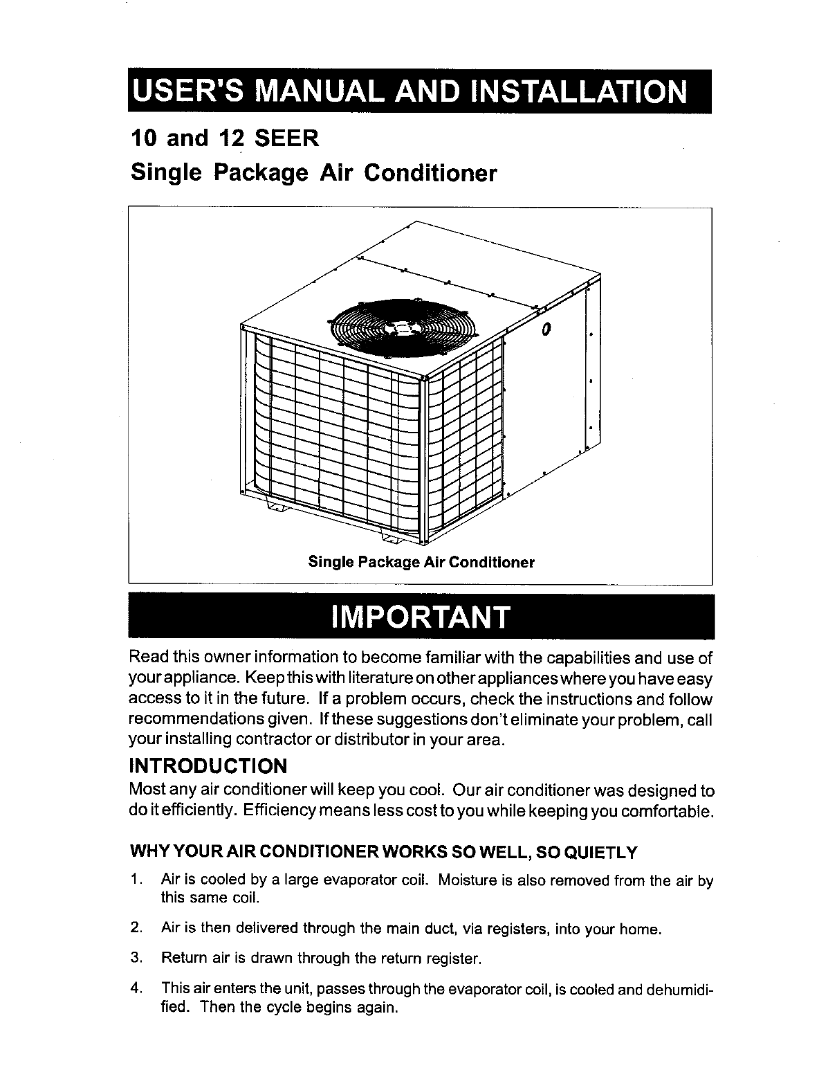
Single Package Air Conditioner
Single Package Air Conditioner
Read this owner information to become familiar with the capabilities and use of
your appliance. Keep this with literature on other appliances where you have easy
access to it in the future. If a problem occurs, check the instructions and follow
recommendations given. If these suggestions don't eliminate your problem, call
your installing contractor or distributor in your area.
INTRODUCTION
Most any air conditioner will keep you cool. Our air conditioner was designed to
do it efficiently. Efficiency means less cost to you while keeping you comfortable.
WHY YOUR AIR CONDITIONER WORKS SO WELL, SO QUIETLY
1. Air is cooled by a large evaporator coil. Moisture is also removed from the air by
this same coil.
2. Air is then delivered through the main duct, via registers, into your home.
3. Return air is drawn through the return register.
4. This air enters the unit, passes through the evaporator coil, is cooled and dehumidi-
fied. Then the cycle begins again.
SECTION t. OWNER INFORMATION
OPERATING INSTRUCTIONS
To Turn On Air Conditioner
If you have a heating/cooling thermostat:
1. Set the system switch to "Cool."
2. Set the thermostat at the temperature level
you desire.
3. Turn the power on. Your air conditioner
should start as soon as room temperature
rises above the setting on the thermostat.
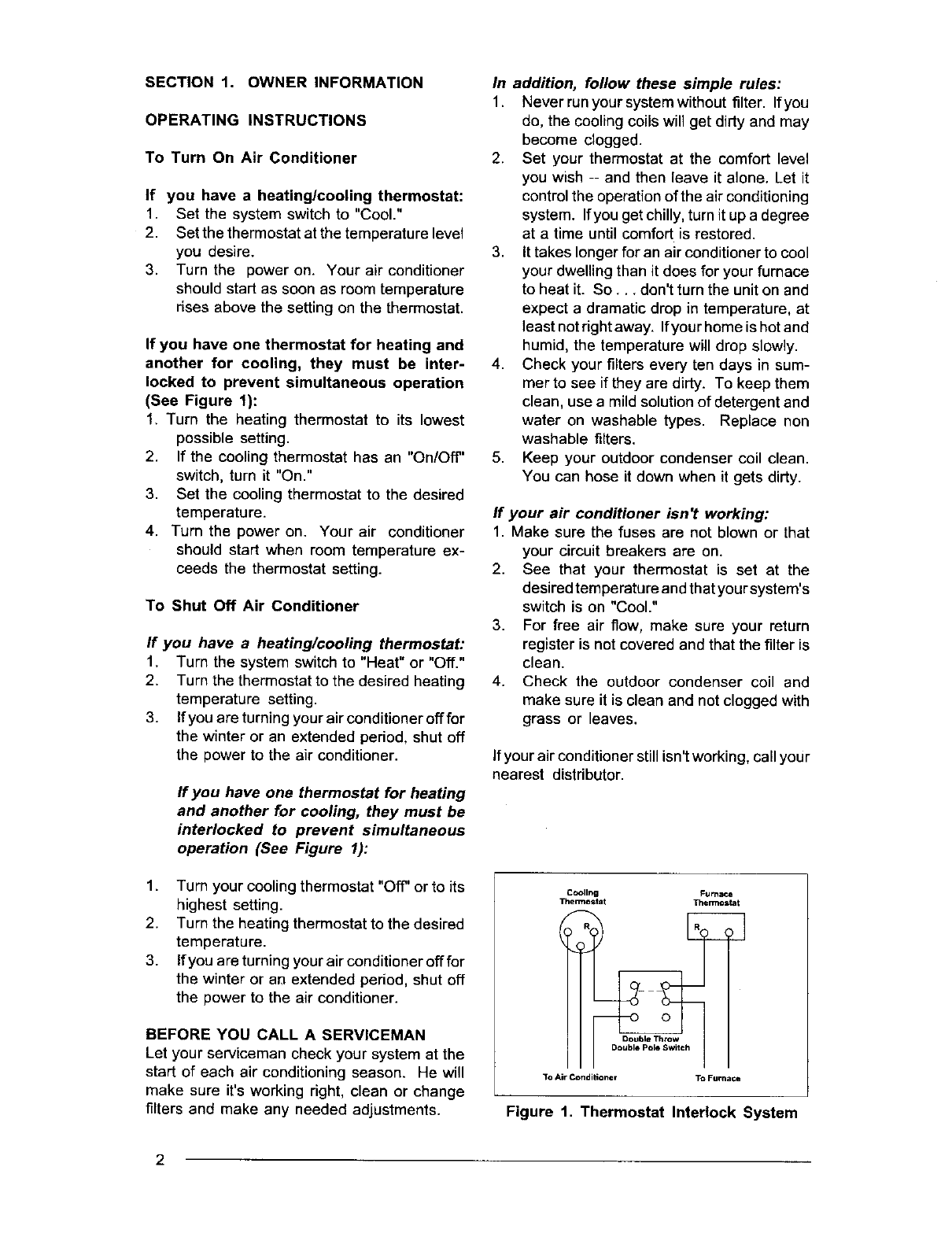
If you have one thermostat for heating and
another for cooling, they must be inter-
locked to prevent simultaneous operation
(See Figure 1):
1. Turn the heating thermostat to its lowest
possible setting.
2. If the cooling thermostat has an "On/Off"
switch, turn it "On."
3. Set the cooling thermostat to the desired
temperature.
4. Turn the power on. Your air conditioner
should start when room temperature ex-
ceeds the thermostat setting.
To Shut Off Air Conditioner
If you have a heating/cooling thermostat:
1. Turn the system switch to "Heat" or "Off."
2. Turn the thermostat to the desired heating
temperature setting.
3. If you are turning your air conditionerofffor
the winter or an extended period, shut off
the power to the air conditioner.
If you have one thermostat for heating
and another for cooling, they must be
interlocked to prevent simultaneous
operation (See Figure I):
1. Turn your cooling thermostat "Off" or to its
highest setting.
2. Turn the heating thermostat to the desired
temperature.
3. If you are turning your air conditioner off for
the winter or aM extended period, shut off
the power to the air conditioner.
BEFORE YOU CALL A SERVICEMAN
Let your serviceman check your system at the
start of each air conditioning season. He will
make sure it'sworking right, clean or change
filters and make any needed adjustments.
In addition, follow these simple rules:
1. Never run your system without filter. Ifyou
do, the coolingcoils will get dirty and may
become dogged.
2. Set your thermostat at the comfort level
you wish -- and then leave it alone. Let it
control the operation of the air conditioning
system. Ifyou get chilly, turn it up a degree
at a time until comfort is restored.
3. It takes longer for an air conditionerto cool
your dwelling than it does for your furnace
to heat it. So... don't turn the unit on and
expect a dramatic drop in temperature, at
least notdght away. Ifyour home is hotand
humid, the temperature will drop slowly.
4. Check your filters every ten days in sum-
mer to see if they are dirty. To keep them
clean, use a mild solutionof detergent and
water on washable types. Replace non
washable filters.
5. Keep your outdoor condenser coil clean.
You can hose it down when it gets dirty.
If your air conditioner isn't working:
1. Make sure the fuses are not blown or that
your circuit breakers are on.
2. See that your thermostat is set at the
desired temperature andthat your system's
switch is on "Cool."
3. For free air flow, make sure your return
register is not covered and that the filter is
clean.
4. Check the outdoor condenser coil and
make sure it is clean and not clogged with
grass or leaves.
if your air conditioner still isn'tworking, call you r
nearest distributor.
Cooling Furnace
Thermostat Thermos1
Double Throw
Double Po_ Switch
3"o Air Conditio TM To Furnace
Figure 1. Thermostat Interlock System
2
SECTION 2. INSTALLER
IN FORMATION
GENERAL
Read the following instructions completely
before performing the installation,
These instructions are for the use of qualified
personnel specially trained and experienced in
the installation of this type of equipment and
related system components. Some states re-
quire installation and service personnel to be
licensed. Unqualified individuals should not
attempt to interpret these instructions or install
this equipment.
The single packaged air conditioners are de-
signed for outdoor installationonly and can be
readily connected into the high static duct
system of a home. The only connections
needed for installation are the supply and return
ducts, the line voltage, and thermostat wiring.
A complete air conditioning system typically
consists of:
•Single Package Air Conditioner
•Home Fittings Kit
•Unit Fittings Kit
• Thermostat
The single package air conditioner is com-
pletely assembled, factory wired, and factory
run tested. The units are ready for easy and
immediate installation.
PRE-INSTALLATION CHECK
Before any installationis attempted, the cooling
load of the area to be conditioned must be
calculated and a system of the proper capacity
selected. It is recommended that the area to be
conditioned be completely insulated and vapor
sealed.
The installer should comply with all local codes
and regulations which govern the installationof
this type of equipment. Local codes and
regulations take precedence over any recom-
mendations contained in these instructions.
Consult local building codes and the National
Electrical Code (ANSI Cl) for special installa-
tion requirements.
Inspecting Equipment: All units are securely
packed at the time of shipment and, upon
arrival, should be carefully inspected for dam-
age. Claims for damage (apparent or con-
cealed) should be filed immediately with the
carrier.
INSTALLATION
1. SELECT THE BEST LOCATION FOR
THE AIR CONDITIONING UNIT
IMPORTANT: DO NOT PLACE UNIT UNDER
THE HOME.
• Select a solid, level position, preferably on a
concrete slab, slightly above the grade level,
and parallel to the home.
• The hot condenser air must be discharged
up and away fi'om the home, and if possible,
in a direction with the prevailing wind.
• De not place the unit in aconfined space.
• If practical, place the air conditioner where it
and the ducts will be shaded from the after-
noon sun when the heat load is greatest.
• Try to select a site for the unitthat is as close
as possible to the proposed return grille
location.
• Keep in mind that the length ofthe supply and
return ducts should be kept to a minimum with
no sharp radiused bends.
2. UNPACK THE UNIT
It is recommended that the unit be unpacked at
the installation site to minimize damage due to
handling.
CAUTION:
Do not tip the unit on its side. Oil may
enter the compressor cylinders and
cause starting trouble. If unit has been
set on its side, restore to upright posi-
tion and do not run for several hours.
Then run unit for a few seconds. Do
this three or four times with five min-
utes between runs.
The electrical supply should be checked to
determine if adequate power is available. If
there is any question concerning the power
supply, contact the local power company.
a. Remove the bands from around the unit.
b. Unfold the top and bottom cap flanges.
c. Carefully remove the top cap and tube.
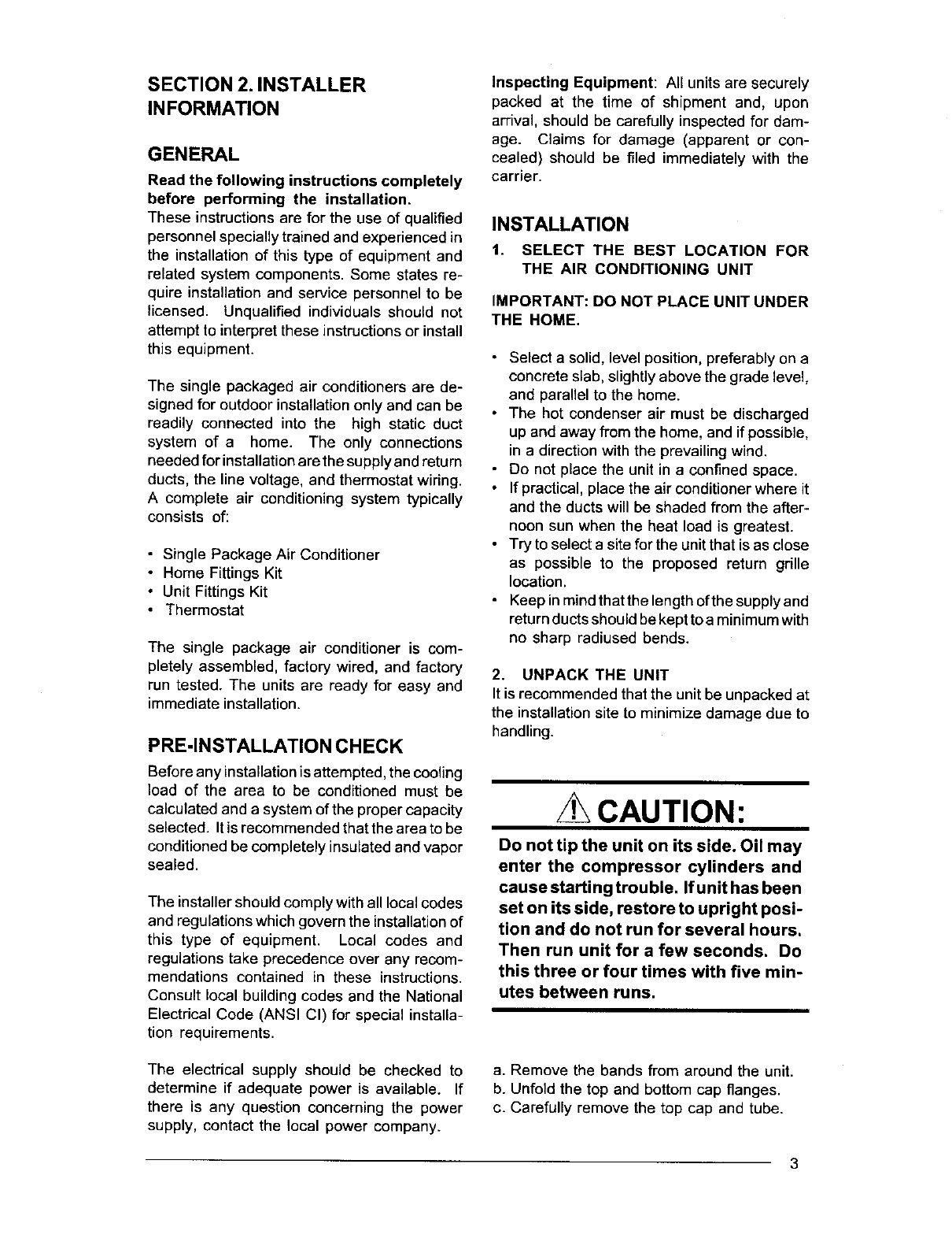
6ft.
Figure 2. Minimum Unit Clearances
3. INSTALL THE RETURN AND SUPPLY
AIR FITTINGS ON THE UNIT
The supply and returnfittings are included with
select models. If supplied, the duct fittings are
shipped in the supply duct. They attach to the
unit openings with a flange and bead arrange-
ment, secured with two sheet metal screws.
Note: For ease of access, install fitting before
positioning unit in final location.
SUPPLY DUCT
Positionthe supplyduct collar, ifsupplied,so the
edge of the unit opening fits between the flange
and the bead. Overlap the collar ends keeping
the small screw holes underneath. Align the
holes inthe crimped area and installone screw.
Note: It may be necessary to loosen the four
screws that hold the transition duct in order to
installthe supply fitting. Re-tighten when instal-
lation is complete.
Tap collar as necessary to ensure engagement
with unit opening and install second screw.
Tighten first screw. Rotate collar clockwise so
joint is near three o'clock position.
RETURN DUCT
The 12" return duct is installed in the same
manner as the supply duct. Ifthe unit has a 14"
return, follow these instructions.
10 SEER Return
Model eia. (in)
2 Ton 12
2 1/2 Ton 12
3Ton 12
3 1/2 Ton 12
4Ton 14
5Ton 14
12 SEER Return
Model Dia. (in)
2 Ton 12
2 1/2 Ton 12
3 Ton 12
3 1/2 Ton 14
4 Ton 14
Align the slots with the holes in the collar and
install two screws. Position the collar over the
opening and align the four notches in the collar
with the four dimples in the panel. Using self-
ddlling screws (10-16x.5) attach the collar to
the rear panel.
4. LOCATING AND INSTALLING THE RE-
TURN AIR ASSEMBLY
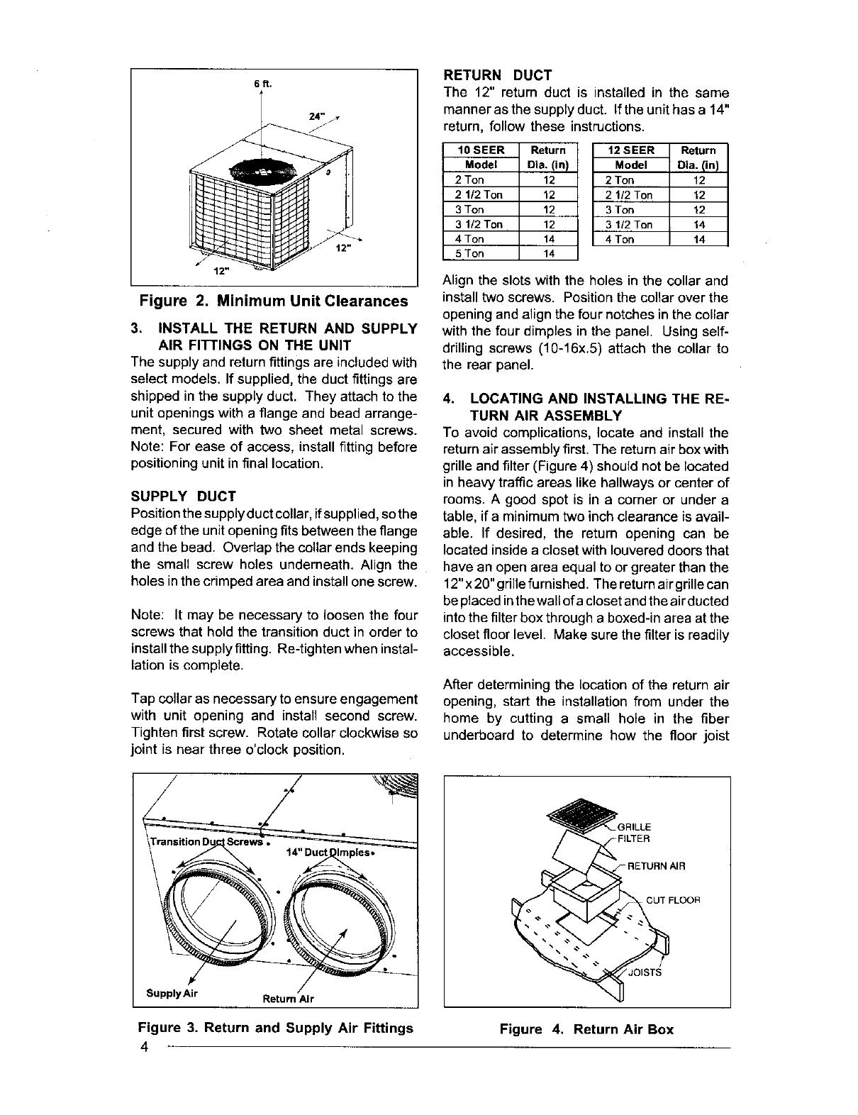
To avoid complications, locate and install the
return air assembly first. The return air box with
grille and filter (Figure 4) should not be located
in heavy traffic areas like hallways or center of
rooms. A good spot is in a corner or under a
table, if a minimum two inch clearance is avail-
able. If desired, the return opening can be
located inside a closet with Iouvered doors that
have an open area equal to or greater than the
12"x 20" grille furnished. The return air grille can
be placed in the wall of acloset and the air ducted
into the filter box through a boxed-in area at the
closet floor level. Make sure the filter is readily
accessible.
After determining the location of the return air
opening, start the installation from under the
home by cutting a small hole in the fiber
underboard to determine hew the floor joist
:ILTER
CUT FLOOR
Supply Air Return Air
Figure 3. Return and Supply Air Fittings
4Figure 4. Return Air Box
location will affect cutting the opening needed
for the box. Floor joists generally are located on
16" centers, leaving 14-3/8" between joists.
After measuring the return air box (approxi-
mately 12-1/4" x 14-1/4"), cut the hole through
the floor so that the box will fit between the floor
joists. Careshould betakenwhen cuttingthrough
carpeting to avoid snags. In most installations
it will be necessary to cut a similar hole in the
fiberboard directly under the hole in the floor.
However, if the floor is more than ten inches
deep, it will only be necessary to cut a hole for
the collar on the return air box orforthe insulated
duct.
Set the box into the opening and fasten with
screws or nails. Put the filter and return air grille
in place.
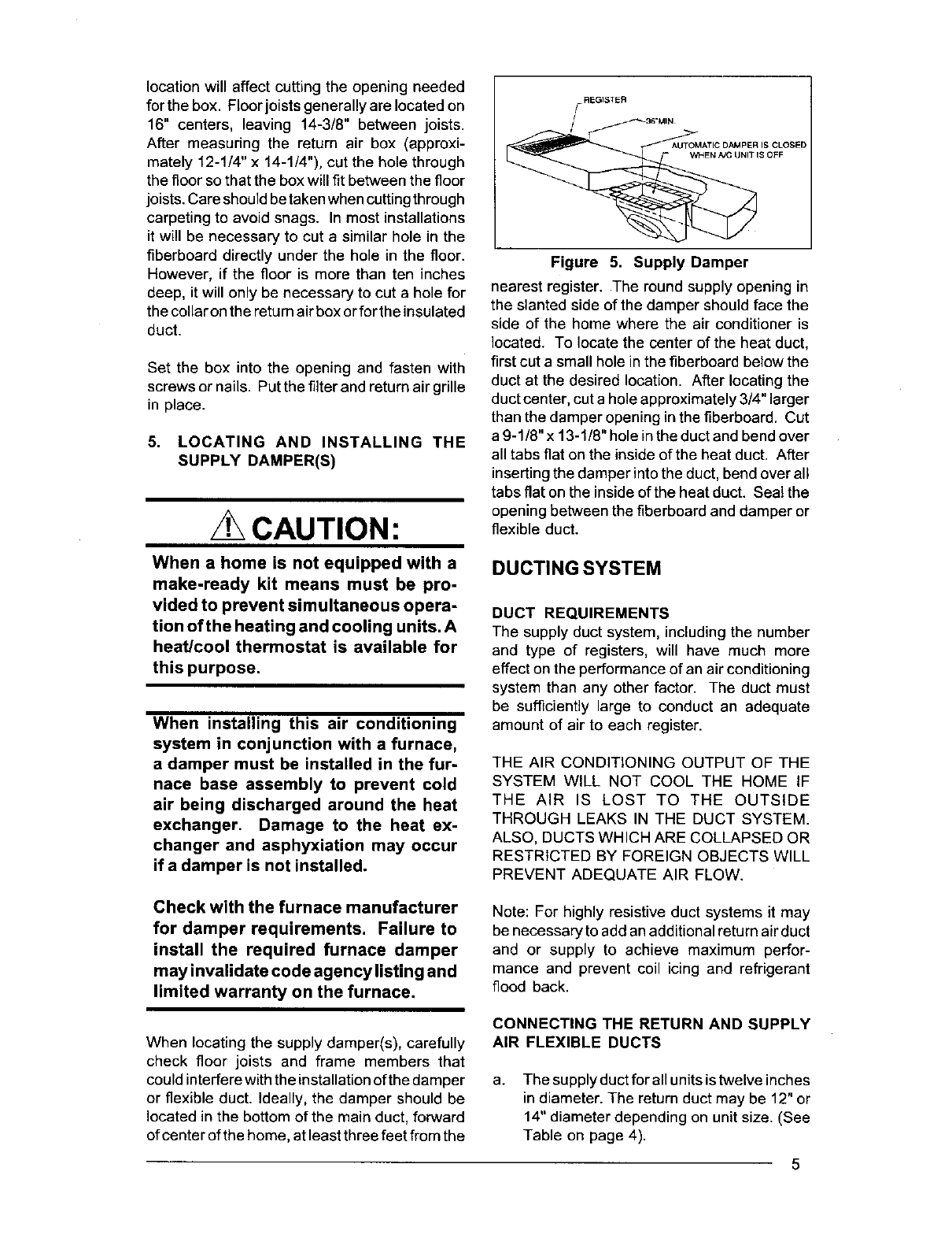
5. LOCATING AND INSTALLING THE
SUPPLY DAMPER(S)
CAUTION:
When a home is not equipped with a
make-ready kit means must be pro-
vided to prevent simultaneous opera-
tion of the heating and cooling units. A
heat/cool thermostat is available for
this purpose.
When installing this air conditioning
system in conjunction with a furnace,
a damper must be installed in the fur-
nace base assembly to prevent cold
air being discharged around the heat
exchanger. Damage to the heat ex-
changer and asphyxiation may occur
ifa damper is not installed.
Figure 5. Supply Damper
nearest register. The round supply opening in
the slanted side of the damper should face the
side of the home where the air conditioner is
located. To locate the center of the heat duct,
first cut a small hole in the fiberboard below the
duct at the desired location. After locating the
duct center, cut a hole approximately 3/4" larger
than the damper opening in the fiberboard. Cut
a 9-1/8" x 13-1/8" hole in the duct and bend over
all tabs flat on the inside of the heat duct. After
inserting the damper into the duct, bend over all
tabs flat on the inside of the heat duct. Seal the
opening between the fiberboard and damper or
flexible duct.
DUCTINGSYSTEM
DUCT REQUIREMENTS
The supply duct system, including the number
and type of registers, will have much more
effect on the performance of an air conditioning
system than any other factor. The duct must
be sufficiently large to conduct an adequate
amount of air to each register.
THE AIR CONDITIONING OUTPUT OF THE
SYSTEM WILL NOT COOL THE HOME IF
THE AiR IS LOST TO THE OUTSIDE
THROUGH LEAKS IN THE DUCT SYSTEM.
ALSO, DUCTS WHICH ARE COLLAPSED OR
RESTRICTED BY FOREIGN OBJECTS WILL
PREVENT ADEQUATE AIR FLOW.
Check with the furnace manufacturer
for damper requirements. Failure to
install the required furnace damper
may invalidate code agency listing and
limited warranty on the furnace.
When locating the supply damper(s), carefully
check floor joists and frame members that
could interferewith the installation of the damper
or flexible duct. Ideally, the damper should be
located in the bottom of the main duct, forward
of center of the home, at least three feet from the
Note: For highly resistive duct systems it may
be necessary to add an additional return air duct
and or supply to achieve maximum perfor-
mance and prevent coil icing and refrigerant
flood back.
CONNECTING THE RETURN AND SUPPLY
AIR FLEXIBLE DUCTS
a. The supply duct for all units istwelve inches
in diameter. The return duct may be 12" or
14" diameter depending on unit size. (See
Table on page 4).
5
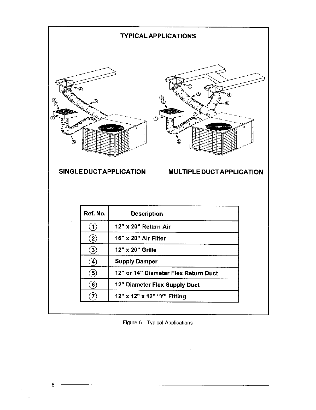
TYPICAL APPLICATIONS
SINGLE DUCTAPPLICATION MULTIPLE DUCTAPPLICATION
Ref. No. Description
(_ 12" x 20" Return Air
(_ 16" x 20" Air Filter
(_ 12" x 20" Grille
(_ Supply Damper
(_ 12" or 14" Diameter Flex Return Duct
(_ 12" Diameter Flex Supply Duct
(_ 12" x t2" x 12" "Y" Fitting
Figure 6. Typical Applications
6
b. The flexible ducts can be connected to the
corresponding fittings with the clamps pro-
vided with the ducts. Note: All connections
should be leak tight or a loss in cooling
capacity will result.
c. The flexible ducts may be cut to the re-
quired length, see instructions packed with
duct. Keep all ducts as short and straight
as possible. Avoid sharp bends.
d. Ducts may be spliced with sheet metal
sleeves and clamps. (See Ducting Instal-
lation Accessories below.)
e. Once the inner duct is connected to the
proper fitting, the insulation and plastic
sleeve should be pulled over the connec-
tion and clamped.
f. For homes with multiple supply ducts or for
special applications, a Y fitting is available
to divide the supply air so it can be ducted
to different areas of the home for more
efficient cooling. Note: The Y fitting should
be insulated for maximum performance.
Blower Speed -- The blower speed is preset at
the factory for operation at the same speed for
heating and cooling. For optimum system
performance and comfort, it may be necessary
to change the factory set speed. To change the
blower speed:
1. Disconnect all electrical power to the unit
and remove the service panel.
2. See Figure 7 for wire color vs. motor speed
guide.
3. Place the desired heating blower speed
lead on the "NO" terminal of the blower
relay. Use another wire tie (field supplied)
JWire Color Motor Speed
Black High
Red Low
Figure 7. Motor Lead Connection
to bundle the remaining motor lead up and
out of the way.
A2 CAUTION:
To avoid personal injury or property
damage, make certain that the motor
leads cannot come into contact with
any uninsulated metal components of
the unit.
Check all factory wiring per the unit wiring
diagram and inspect the factory wiring connec-
tions to be sure none loosened during shipping
or installation.
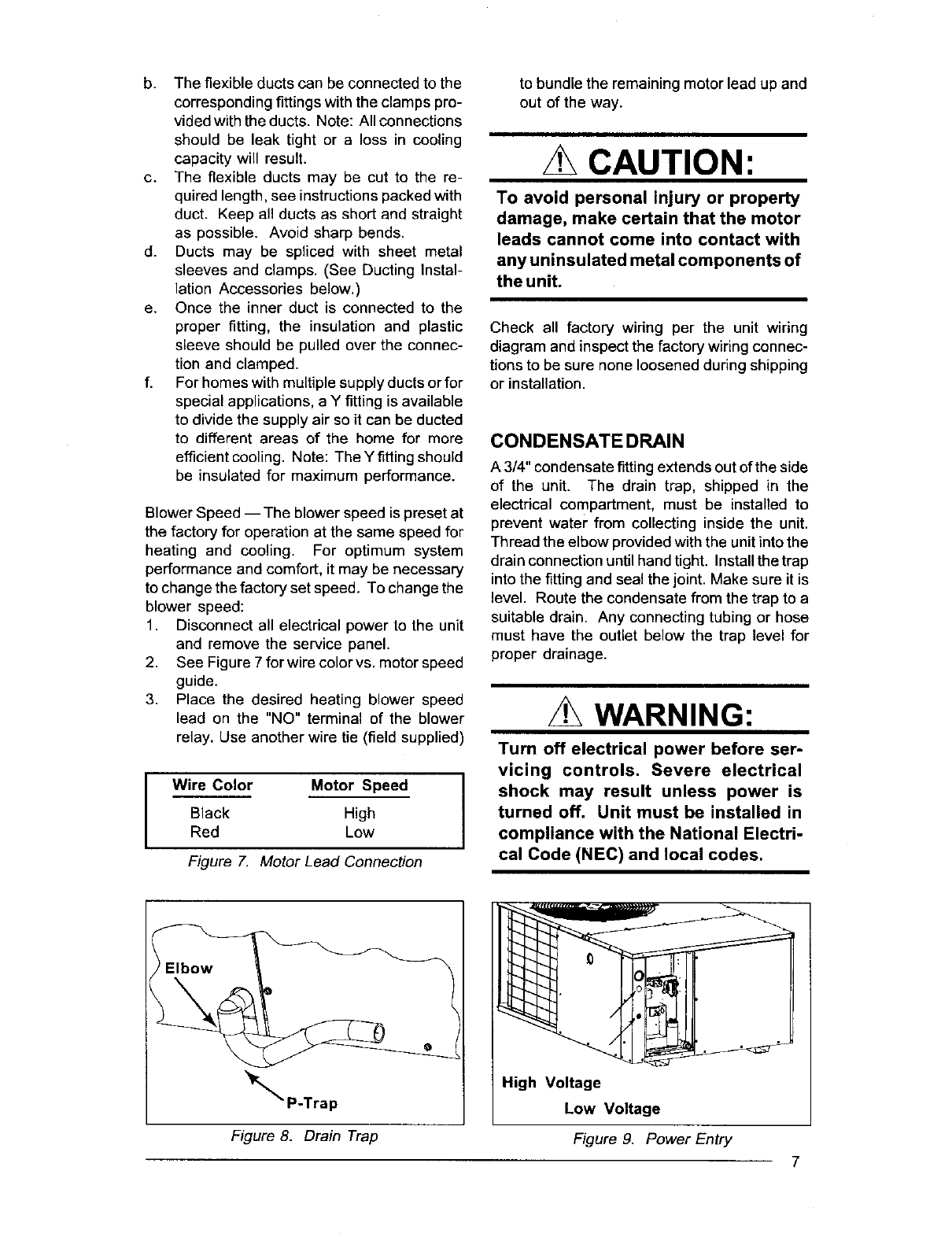
CONDENSATE DRAIN
A 3/4" condensate fitting extends out of the side
of the unit. The drain trap, shipped in the
electrical compartment, must be installed to
prevent water from collecting inside the unit.
Thread the elbow provided with the unit into the
drain connection until hand tight. Install the trap
into the fitting and seal the joint. Make sure it is
level. Route the condensate from the trap to a
suitable drain. Any connecting tubing or hose
must have the outlet below the trap level for
proper drainage.
WARNING:
Turn off electrical power before ser-
vicing controls. Severe electrical
Ishock may result unless power is
turned off. Unit must be installed in
compliance with the National Electri-
cal Code (NEC) and local codes.
Elbow
_P-Tra p
Figure 8. Drain Trap
High Voltage
Low Voltage
Figure 9. Power Entry
7
ELECTRICAL CON NECTIONS
1. ELECTRICAL SERVICE
High Voltage
a. Install a branch circuit disconnect of ad-
equate size per NEC. Locate the discon-
nect within sight of the unit.
b. Extend leads through power wiring hole
provided. Connect L1 and L2 directly to the
contactor. (See Figure 9).
c. Ground the air conditioning unit using the
green grounding screw provided in the
control panel.
Low Voltage
a. Route 24v control wires through the seal-
ing grommet near the power entrance.
b. Connect the control wires to the leads in the
low voltage area. (See Figure 10).
2. OVERCURRENT PROTECTION
In general, the best fuse or breaker for any air
conditioner is the smallest size that will permit
the equipment to run under normal use and
service without nuisance trips. Such a device,
sized properly, gives maximum equipment pro-
tection. The principal reason for specifying a
time delay type is to prevent nuisance trips
when the unit starts.
In the event that a fuse does blow or a breaker
trips, always determine the reason. Do not
arbitrarily put in a larger fuse or breaker and do
not, in any case, exceed the maximum size
listed on the data label of the unit.
3. LOCATING THE THERMOSTAT
Locate the thermostat away from drafts and
slamming doors and place it where there is a
free flow of air. Mount on an inside wall approxi-
mately five feet from the floor.
Do not locate near a lamp, kitchen range, direct
sunlight, or in line with air flow from supply
registers.
a. Connect Cooling Thermostat: The
cooling thermostat available for use with
this system is equipped with a selector
switch. To shut down the air conditioner,
set the selector switch to the OFF position.
Connect the red and yellow wires from the
unit to the R and Y terminals respectively
on the thermostat subbase. Connect the
green wire to the yellow wire atthe unit. See
the instruction sheet packed with the ther-
mostat for detailed methods of mounting.
Note: The cooling-only thermostat must
be connected to an interlock switch to
prevent simultaneous operation of the fur-
nace and the air conditioner. (See Figure 1,
Page 2.)
b, Connect the Heat-Cool Thermostat:
The heat-cool thermostat is equipped with
asystem HEAT-COOL switch, which pro-
vides a positive means of preventingsimul-
taneous operation of the heating and cool-
ing units. The thermostat is also equipped
with an ON-AUTO fan switch which allows
the home owner to operate the indoor
blower when air circulation is desired.
Connect the red, yellow, green and brown
tow voltage wires to the R or RC, Y, G and
W terminals respectively on the thermo-
stat base. The black wire is the 24 volt
common required on some thermostats.
See thermostat instruction sheet for more
detailed information.
Refer to furnace installationinstructionsfor
required connections and proper heat an-
ticipator setting when installing unit with an
external furnace.
Co If two stage heating is desired, an
optional outdoor thermostat may be
installed: Connect the thermostat to the
orange low voltage wire and the W terminal
on the indoorthermostat base (See Figure
10). See the thermostat instructions for
details on setting the outdoor thermostat.
4, ELECTRIC HEAT PACKAGE (OP-
TIONAL)
The air conditioner is shipped without an aux-
iliary electric heat kit installed. If electric heat is
desired, an accessory Heater Kit must be field
installed. See Specifications Sheet for available
kits and their applications.
Select the correct size heat package for
the installation.
8
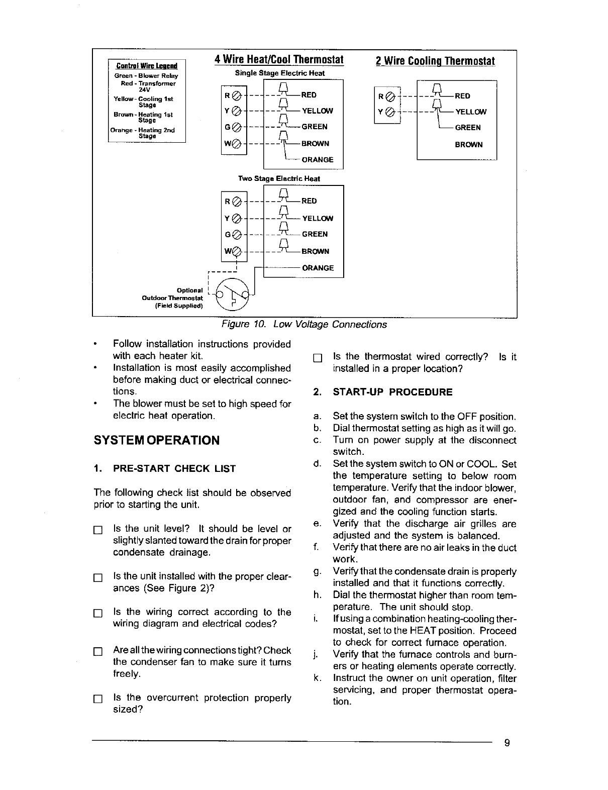
Control Wire Leuend
Green -Blower Relay
Red - Transformer
24V
Yellow -Cooling 1st
Stage
Brown -Heating 1st
Stage
Orange -Heating 2nd
Stage
4 Wire Heat/CoolThermostat
Single Stage Electric Heat
- - -_ YELL_
ORANGE
2 Wire CoolinqThermostat
BROWN
Two Stal
I
i......
I
Optional •: __
Outdoor Thermostat
(Field Supplied)
e Electric Heat
---_RED
- - -_ YELLOW
_ _ __L_ GREEN
__ __L_ BR(_N N
-- ORANGE
Figure 10. Low Voltage Connections
Follow installation instructions provided
with each heater kit.
Installation is most easily accomplished
before making duct or electrical connec-
tions.
The blower must be set to high speed for
electdc heat operation.
SYSTEM OPERATION
1. PRE-START CHECK LIST
The following check list should be observed
prior to starting the unit.
[] Is the unit level? It should be level or
slightly slanted toward the drain for proper
condensate drainage.
[] Is the unit installed with the proper clear-
ances (See Figure 2)?
[] Is the wiring correct according to the
wiring diagram and electrical codes?
[]
[]
Are all the wiringconnections tight? Check
the condenser fan to make sure it turns
freely.
Is the overcurrent protection properly
sized?
[] Is the thermostat wired correctly? Is it
installed in a proper location?
2. START-UP PROCEDURE
a. Set the system switch to the OFF position.
b. Dial thermostat setting as high as it will go.
c. Turn on power supply at the disconnect
switch.
d. Set the system switch to ON or COOL. Set
the temperature setting to below room
temperature. Verify that the indoor blower,
outdoor fan, and compressor are ener-
gized and the cooling function starts.
e. Verify that the discharge air grilles are
adjusted and the system is balanced.
f. Verify that there are no air leaks in the duct
work.
g. Verify that the condensate drain is propedy
installed and that it functions correctly.
h. Dial the thermostat higher than room tem-
perature. The unit should stop.
i. If using a combination heating-cooling ther-
mostat, set to the HEAT position. Proceed
to check for correct furnace operation.
j. Verify that the furnace controls and burn-
ers or heating elements operate correctly.
k. Instruct the owner on unit operation, filter
servicing, and proper thermostat opera-
tion.
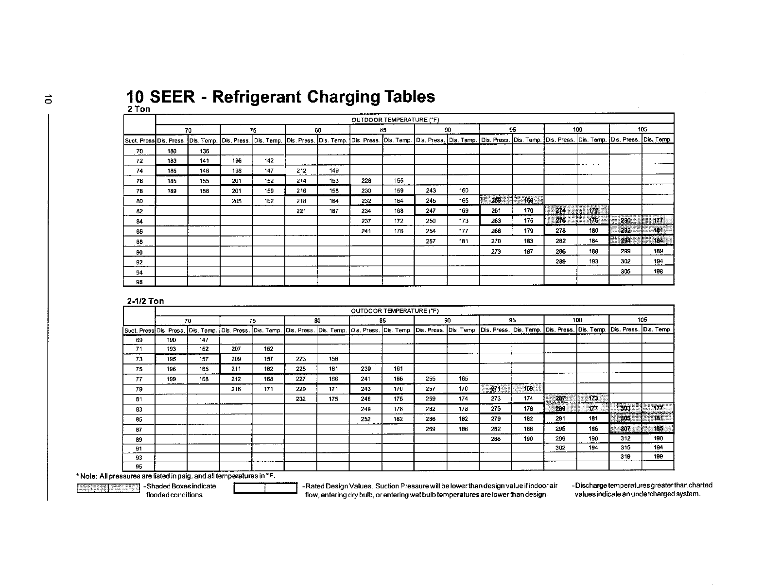
10 SEER -Refrigerant Charging Tables
2 Ton
OUTDOOR TEMPERATURE !°F!
70 75 80 85 90 95 100 105
5ucL Press Dis Press.! _is. Temp. Dis. Press Dis. Temp DIS Press. Dis. Temp 3s Press. Dis Temp 3is. Press. Dis Temp• Dis. Press• )is. Temp Dis. Press. Dis. Temp. Dis. Press• Dis. Temp,
70 180 136
72 183 141 196 142
74 185 146 198 147 212 149
76 185 155 201 152 2!4 153 228 155
78 189 158 201 159 216 158 230 159 243 160
80 z05 162 218 1_ 232 1_ 245 18_
82 221 167 234 tB8 247 169 261 170 _ i_'_:_
86 241 176 254 177 266 179 278 180 _ i_ " _
88 257 181 270 183 282 184 _ _;_4_J:_. _ _!i:_ _
90 273 187 286 188 299 189
92 289 193 302 194
94 305 198
96
2-1/2 Ton
OUTDOOR TEMPERATURE ('F)
70 75 80 85 90 95 100 105
Suet. Press Dis. Press )is Temp. Dis Press Dis. Temp. Dis. Press Dis Temp. DIS. Press Dis, Temp Dis. Press. Dis Temp. Dis. Press. Dis. Temp. Dis. Press _)is Temp. DIS, Press. Dis. Temp.
69 190 147
71 193 152 207 152
73 195 157 209 157 223 156
75 196 165 211 162 225 161 239 161
77 199 168 212 168 227 166 241 166 255 165
79 216 171 229 171 243 170 257 170 _ !_!!!!_! !_i;_;_i_i_!!_
81 232 175 246 175 259 174 273 174 :_7
85 252 182 266 182 279 182 291 181 _
87 269 186 282 186 295 186
89 286 190 299 190 312 190
91 302 194 315 194
93 319 199
95
* Note; All pressures are listed in psig. and all temperatures in °F.
-Shaded Boxesindicate I J I -Rated Design Values. Suction Pressure will be lower than design value if indoor air - Discharge temperaturesgreater thancharted
flooded conditions flow, entering dry bulb, or entering wet bulb temperatures a re lower than d esign, values indicate an undercharged system.
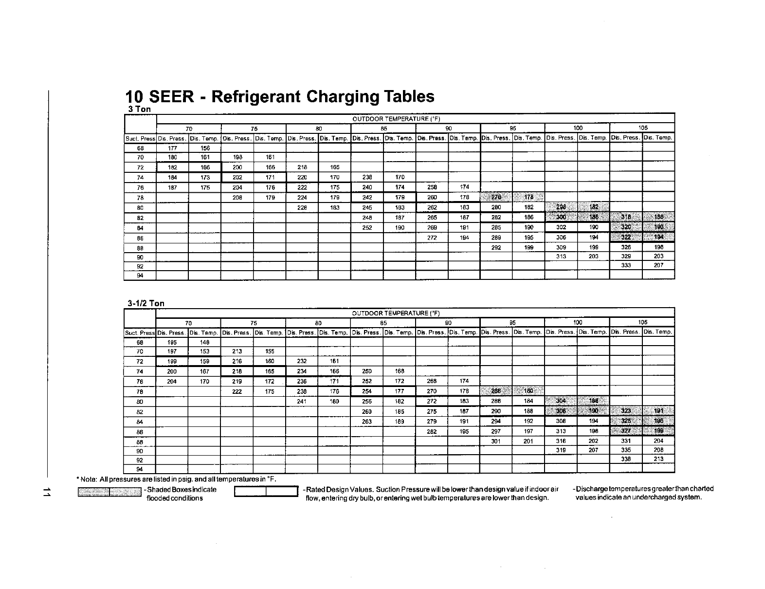
10 SEER -Refrigerant Charging Tables
3 Ton
OUTDOORTEMPERATURE('F)
70 75 80 85 90 95 100 105
Suct. Pres_ D_ Press, Dis Temp. De. Press. D_.Temp. Oh. Press. D_.Temp Dis. Press Dis Temp. Dis. Press. )_.Temp DIS. Press, Dis,Temp. DIS. Press )is. Temp Dis,Press. Dis. Temp.
68 177 156
70 180 161 198 161
72 182 166 20(I 166 218 165
74 184 173 202 171 220 170 238 170
76 187 175 204 176 222 175 240 174 258 t74
78 208 179 224 179 242 179 260 178 _
80 228 183 245 183 262 183 280 182
82 248 187 265 187 282 186 ......_ _,4_, i_i_!% _ii_18_,_!
84 252 190 269 191 285 190 302 190 _!i_
86 272 194 289 195 306 194 ii_i_ i _4_;_
88 292 199 309 199 326 198
90 313 203 329 203
92 333 207
94
3-1/2 Ton
OUTDOOR TEMPERATURE ('F)
70 75 80 85 90 g5 100 105
p
_uct Press D=s. tess 3is Temp Dis. Press. Dis Temp DIS Press. Dis. Temp. Dis. Press, Dis Temp. Dis. Press. Dis. Temp _is. Press. Dis. Temp. Dis. Press. Dis. Temp. DIS Press Dis. Temp.
68 195 148
70 !97 153 213 155
72 199 159 216 160 232 161
74 200 167 218 1_5 234 166 250 _68
76 204 170 219 172 236 _71 252 172 268 t74
78 222 175 238 176 254 177 270 178
80 241 180 256 182 272 183 288 184
82 260 185 275 187 290 188 !_!_; :_ ......
84 263 189 279 191 294 192 308 194
86 282 195 297 197 313 198 _ _!;_,i
88 301 201 316 202 331 204
90 31g 207 335 208
92 338 213
94
*Note: All pressures are listed in psig. and all temperatures in °F.
-Shaded Boxesicdicate II I -RatedDesignValues. SuctionPressurewillbelowerthandesignvalueifindoorair - Discharge temperatures g rearer than charted
flooded condilion s flow, entering d_ bulb, o rentering wet bulb temperatures are lower th an design, values indicate an undercharged system.
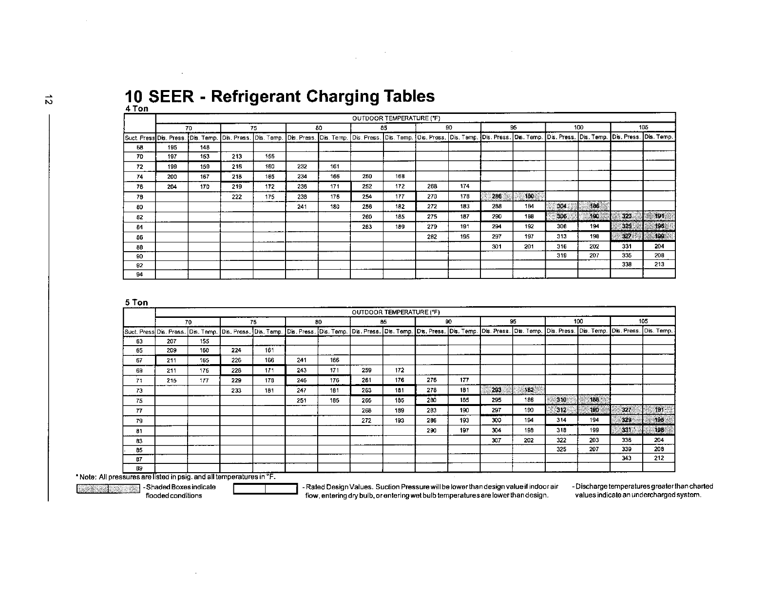
10 SEER -Refrigerant Charging Tables
4 Ton
OUTDOOR TEMPERATURE ('F}
70 75 80 85 90 95 !00 105
)uct Press Dis, Press Dis Temp. Dis. Press. Dis. Temp. Dis. Press. Dis Temp Dis Press, Dis Temp.!3=s. Press. Dis Temp, Dis Press. Dis. Temp. D_s. Press. )is. Temp Dis,Press )is. Temp.
68 195 148
70 197 153 213 155
72 199 159 216 160 232 161
74 200 167 218 165 234 166 250 168
76 204 170 219 172 236 171 252 172 268 174
78 222 175 238 176 254 177 270 !78
80 2,,,1 _ 256 182 272 183 2s8 1_ ii:_ _
82 260 185 275 187 290 !B8
84 263 189 279 191 294 192 308 194 _ _ _i_
86 282 195 297 197 313 198 ! !_:_! _ t_t_ _
88 301 201 316 202 331 204
90 319 207 335 208
92 338 213
94
5 Ton
OUTDOOR TEMPERATURE (=F)
70 75 80 85 90 95 100 105
Suct. Press Dis Press. Dis. Temp. Dis. Press. l)is. Temp Dis Press D_s, Temp Dis. PreSs. Dis Temp. )m. Press. Dis, Temp )is Press. Dis. Temp. Dis. Press. Dis. Temp. Dis. Press )is. Temp.
63 207 155
65 209 160 224 161
67 211 165 226 166 241 166
69 211 175 228 171 243 171 259 172
71 215 177 229 178 246 176 261 176 276 177
73 233 18! 247 181 263 181 278 181 ii_i_93ii!ii_
.... i,, ,ri,,
75 251 185 265 185 280 185 295 _86
7: 268 18o 2B3 190 297 19o !;_!_t'%! i';_m'_'
79 272 193 286 193 300 194 314 194 _! _ _
83 3_7 202 322 203 336 204
85 325 207 339 208
87 343 212
89
*Note: All pressures are listed in psig, and all temperatures in °F.
-Shaded Boxesindicate -RatedDesignValues. SuctionPressurewillbelowerthandesignvalueifindoorair - Discharge temperaturesgreater than chaded
flooded conditions I I I flow, entering dry bulb, or entedng wet bulb temperatures are lower than design, values indicate an undercharged system.
c_a
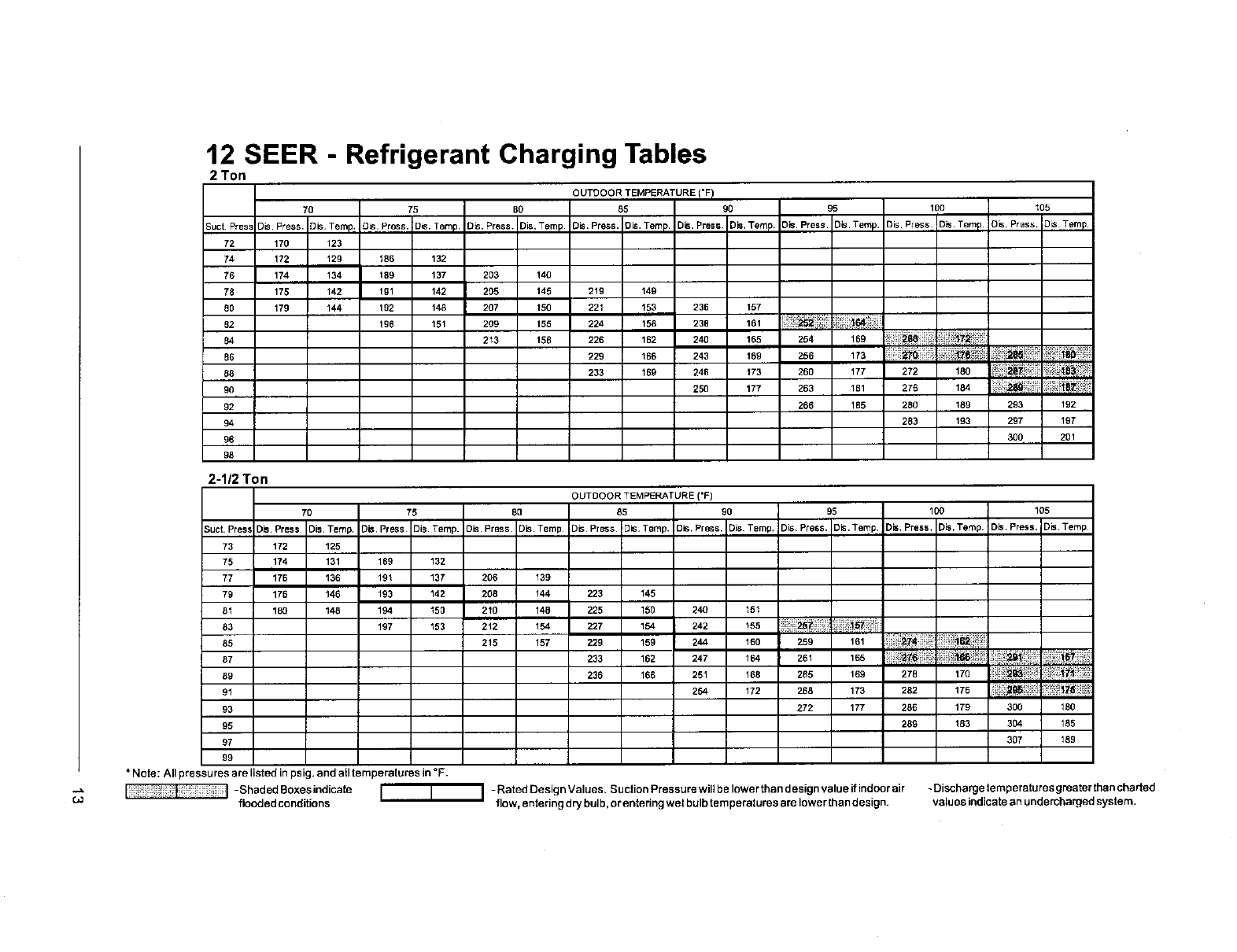
12 SEER -Refrigerant Charging Tables
2 Ton
OUTDOOR TEMPERATURE I"FI
70 75 80 85 90 95 100 105
Suct Press Dis. Press. DIS, Temp. DIS Press. Dis. Temp. DIS. Press. )is. Temp Dis. Press. Dis. Temp. Dis. Press Dis, Temp. 3is Press. Dis. Temp. )isPress. Dis. Temp.! DIS. Press. D_Temp
72 170 123
74 172 129 186 132
76 174 134 189 137 203 140
78 175 142 1gl 142 205 145 219 149
80 179 144 192 148 207 150 221 153 236 157
B2 196 151 209 155 224 158 23B 161
B4 213 158 226 162 240 165 254 169
B6 229 188 243 189 256 173 iiii_! ;-_;it
88 233 169 246 173 260 177 272 180 _i_ _B_'_!
90 250 177 263 1B1 276 184 _i_1_ _ii_ ii!i_!_8_:
92 266 185 280 189 293 192
94 283 193 297 197
96 300 201
98
2-1/2 Ton
OUTDOOR TEMPERATURE (=F)
70 75 BO 85 90 95 100 105
Suct. Pres! )is. Press Ois. Temp, )is, Press Dis. Temp. Dis. Press Dis. Temp Dis Press ]is, Temp. Dis. Press. Dis Temp, Dis Press. Dis. Temp. Dis Press, Dis,Temp. )is. Press. Dis Temp,
73 172 125
75 174 131 189 132
77 175 136 191 137 206 139
79 176 146 193 142 208 !44 223 145
B1 180 148 194 150 210 14B 225 150 240 151
83 197 153 212 154 227 154 242 155
85 215 157 22_ ls9 2,_ 180 2s9 161
B7 233 162 247 164 261 165
89 236 166 251 168 265 169 27B 170
91 254 172 26B 173 282 175 _" '_}_ii! _
93 272 177 286 179 300 180
95 289 183 304 185
97 307 189
99
*Note: All pressures are listed in psig. and all temperatures in °F.
-ShadedBoxesindicate I I I -RatedDesignValues. SuctionPressurewillbelowerthandesignvalueifirldoorair -Dischargetemperaturesgreaterthanchaded
flooded conditions flow, entering dry bulb, or entering wet bulb tern peratures are lower than design, values indicate an undercharged system.
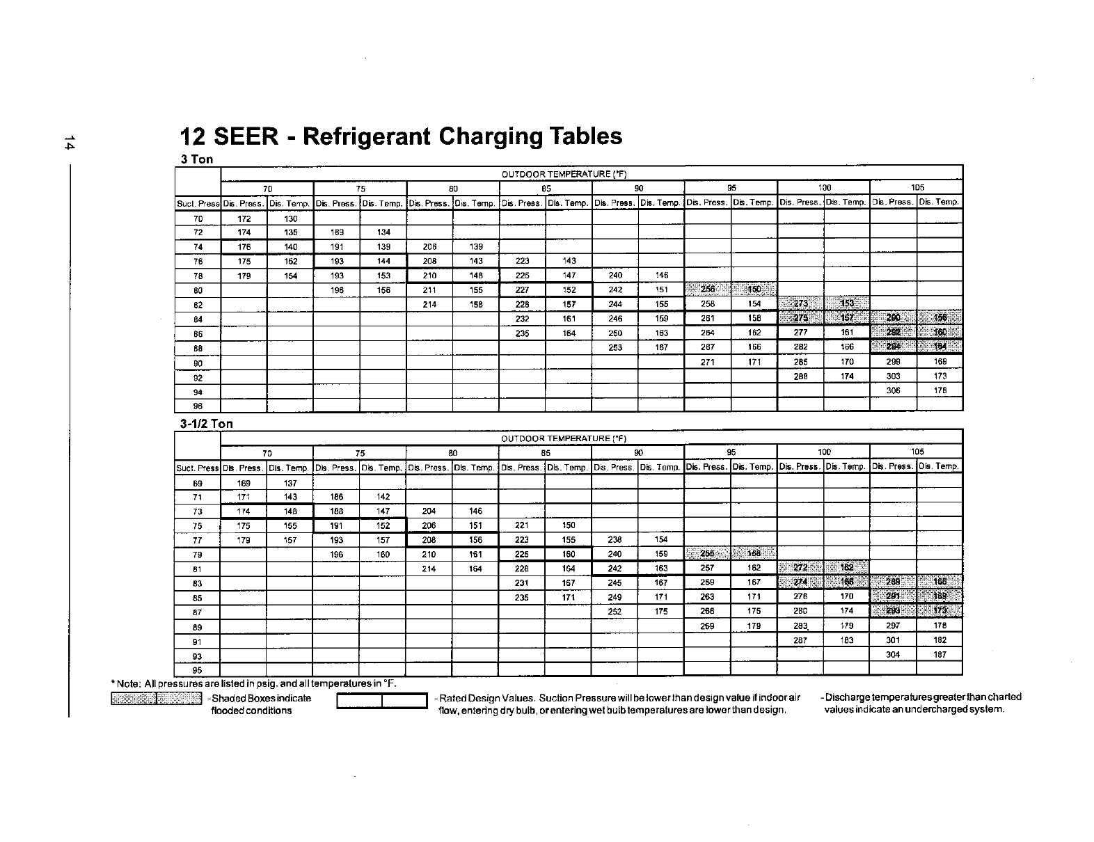
12 SEER - Refrigerant Charging Tables
3 Ton
OUTDOOR TEMPERATURE I'F)
70 75 80 85 90 95 100 105
Suct. PresJ 3is Press. Dis. Temp Dis Press. Dis Temp. Dis. Press. 3_s.Temp D=s,Press Dis. Temp. Dis. Press Dis,Temp Dis. Press. Dis. Temp. )is Press, Dis. Tgmp. )is. Press. Dis,Temp
70 172 130
72 174 135 1B9 134
74 176 140 191 139 206 139
76 175 152 193 144 208 143 223 143
78 179 154 193 153 210 148 225 147 240 146
B0 196 156 211 155 227 152 242 151
82 214 158 228 157 244 155 258 154
84 232 161 246 159 261 158 !:_
86 235 164 250 163 264 162 277 161
88 253 167 267 166 282 1B6 _i_ ;
90 271 171 285 170 299 169
92 288 174 303 173
94 306 178
96
3-1/2 Ton
OUTDOOR TEMPERATURE ('F)
70 75 80 85 90 95 100 105
Suct Pres= ]is Press Dis. Temp )is Press. DIS Temp, Dis. Press. Dis Temp. Dis. Press. )is. Temp. Dis. Press 3is Temp. Dis. Press. Dis. Temp. Dis. Press Dis,Temp )is. Press. Ois. Temp
69 169 137
71 171 143 186 142
73 174 148 188 147 204 146
75 175 155 191 152 206 151 221 150
77 179 _57 193 157 208 156 223 155 238 154
79 196 160 210 _61 225 160 240 159
81 214 164 228 164 242 163 257 162 _i_ _ P_
tff
83 231 167 245 167 259 167
85 235 171 249 171 263 171 276 17o _i_:_,_,_
87 252 175 266 175 280 174 ;_ _?
89 269 179 283 179 297 178
91 287 183 301 182
93 304 187
95
* Note: All pressures are listed in psig. and all temperatures in °F.
-Shaded Boxesindicate I I I -Rated Design Values. Suction Pressure will belower than design value if indoor air - Discharge temperatures greater than charted
flooded conditions flow, entedng dry bulb, or entering wet bulb temperatures are lower than design, values indicate an undercharged system,
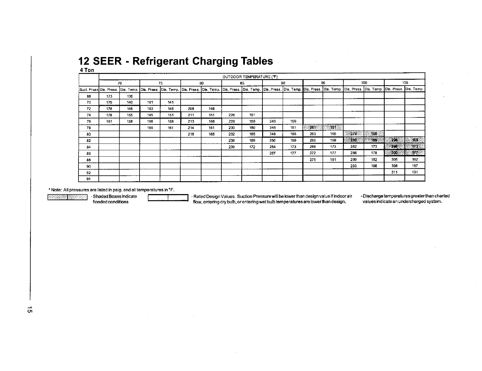
12 SEER - Refrigerant Charging Tables
4 Ton
OUTDOOR TEMPERATURE (°F)
70 75 80 85 90 95 100 105
Suct. Pres! )is. Press Dis. Temp. ]is. Press. Dis. Temp Dis. Press. ]is, Temp DIS. Press. ]is Temp. Dis. Press. ]is. Temp. Dis. Press. Dis. Temp. Dis. Press )is. Temp. Dis. Press. Dis. Temp.
68 173 135
70 175 140 191 141
72 178 146 193 146 208 146
74 178 155 195 151 211 151 226 151
76 181 158 196 158 213 156 228 156 243 156
78 199 161 214 161 230 160 246 161 _2_ 1_
80 218 165 232 165 248 165 263 165 _;;
82 236 169 250 169 265 169
84 239 172 254 173 268 173 282 173 _ _ ;
86 257 177 272 177 286 178 _,;_:_ ?"
88 275 181 290 182 305 182
90 293 186 308 187
92 311 191
94
* Note: All pressures are listed in psig. and all temperatures in °F.
_ _:: I_, ] -Shad_lBoxesindicate I ' ] I -RatedDesignValues. SuctionPressurewillbelowerthandesignvalueifindoorair -Dischargetemperaturusgreaterthanchaded
flooded conditions flow, entering dry bulb, orentering wet bulb ternperatures are lower than design, values indicate an undercharged system.
INSTALLER
PLEASE LEAVE THESE
INSTALLATION INSTRUCTIONS
WITH THE HOMEOWNER.
IIIIIIIIIIIIIIIIIIII 708298A(Replaces 7082980)
Specifications and illustrations subject to change
without notice and without incurring obligations.
708298A PrlntedinU.S.A.(11/03)
