NX System NX-100 PROXIMITY ACCESS READER User Manual Product parameters
NX System Inc. PROXIMITY ACCESS READER Product parameters
UserManual.wiki
>
NX System
>
NX 100 User Manual
user manual
Navigation menu
Upload a User Manual
Namespaces
Wiki Guide
HTML
PDF
Info
Views
User Manual
Discussion / Help
Navigation
![1. Important Safety Instructions When using the 13.56MHz [MIFARE] Contactless Smart Card Reader, basic safety precautions should always be followed to reduce the risk of fire, electrical shock, and injury to persons. In addition, the following should also be followed: Fully read and understand all instructions and follow them completely. Follow all warnings and instructions marked on the product. Do not use liquid or aerosol cleaners. Use a damp cloth for cleaning. If necessary, use mild soap. Do not use this product near water. Only operate this product using the type of power source indicated. If you are not sure of the type of power supplied to your installation site, consult your dealer of local power company. Never insert objects of any kind into the product or through the cabinet slots as they may touch voltage points and/or short circuit parts possibly resulting in fire or electric shock. Never spill liquid of any kind on the product. Never disassemble this product by yourself; take the unit to a qualified service center whenever service or repair is required. Opening or removing the covers may expose you to dangerous voltages or other risks. Also, incorrect reassembly can cause electric shock when the unit is subsequently used. Unplug this product from the Direct Current (DC) power source and refer to qualified service personnel under these conditions: a. When the power supply cord or plug is damaged or frayed. b. If liquid has been spilled on the product. c. If the product does not operate normally after following the operating instructions in this manual. Adjust only those controls that are covered by the operating instructions in this manual. Improper adjustment of other controls that are not covered by this manual may damage the unit and will often require extensive work by a qualified technician to restore normal operation. d. If the product exhibits a distinct change in performance. 2. General](https://usermanual.wiki/NX-System/NX-100/User-Guide-1803418-Page-5.png)
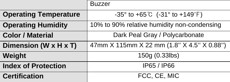
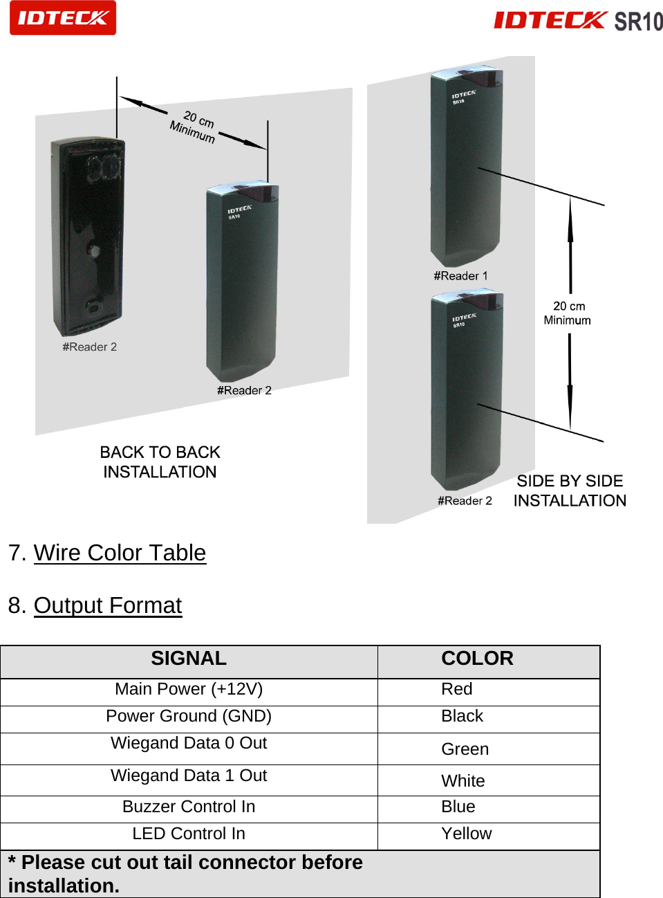
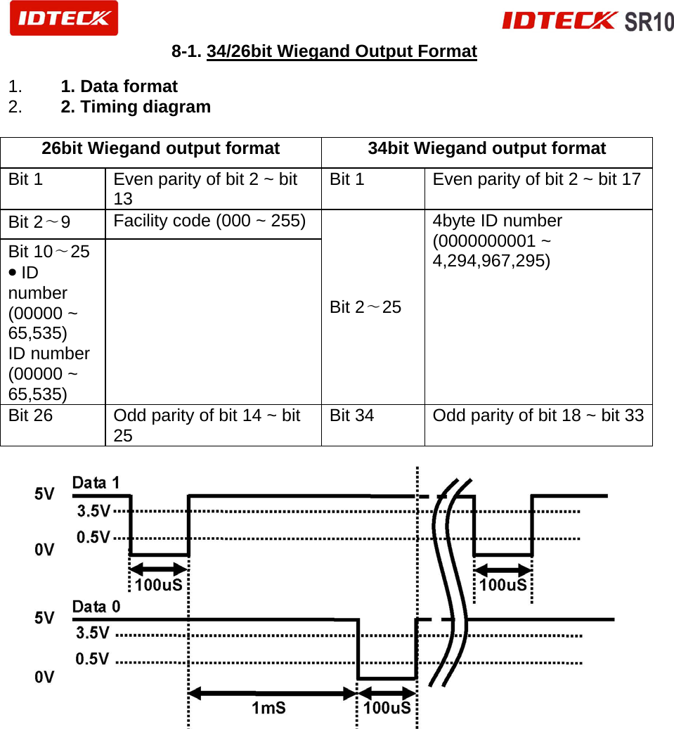
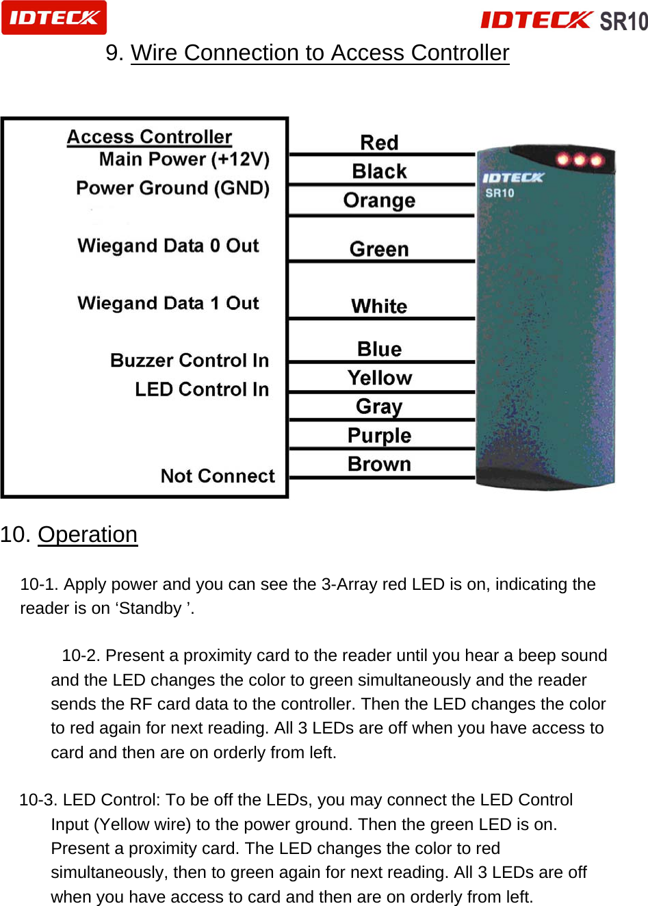
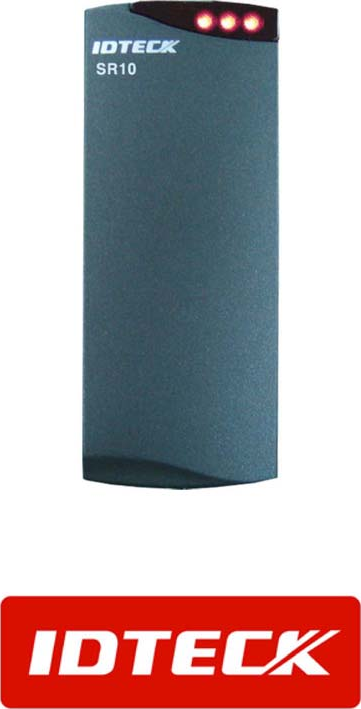
![3. Features - 13.56MHz [MIFARE] Contactless smart Card Reader / Writer -ISO 14443 type A compatible -Sector Number Read only -Read Range: Up to 3 inch (6cm) .- 26bit Wiegand Output Format .- 3 Array LED Indicators (Red and Green) and Beeper .-External LED Control .-External Buzzer Control - Easy to install on Mullion Mounting suitable -Solid Epoxy Potted .- Waterproof / IP65 / IP66 .- Warranty: Life Time -Reverse Polarity Protection -Compatible Software: Smart Card Read / Write Software - Compatible Controller: iCON100SR, iTDC-SR, Third Party Controller 4. Identifying Supplied Parts Please unpack and check the contents of the box: 5. Specification Model SR10 Reading Time (Card) 30ms Power / Current DC12V / Max.80mA Input Port 2ea (External LED Control, External Buzzer Control) Output Format 26bit Wiegand LED Indicator / Beeper 3 Array LED Indicators (Red, Green) / Piezo](https://usermanual.wiki/NX-System/NX-100/User-Guide-1803418-Page-7.png)