NXP Semiconductors JN5169U0V2 ZigBee Modular Transmitter User Manual UM11030
NXP Semiconductors ZigBee Modular Transmitter UM11030
UserManual.wiki
>
NXP Semiconductors
>
JN5169U0V2 User Manual
>
User manual rev.pdf
Contents
1.
User manual
2.
User manual rev.pdf
User manual rev.pdf
Navigation menu
Upload a User Manual
Namespaces
Wiki Guide
HTML
PDF
Info
Views
User Manual
Discussion / Help
Navigation
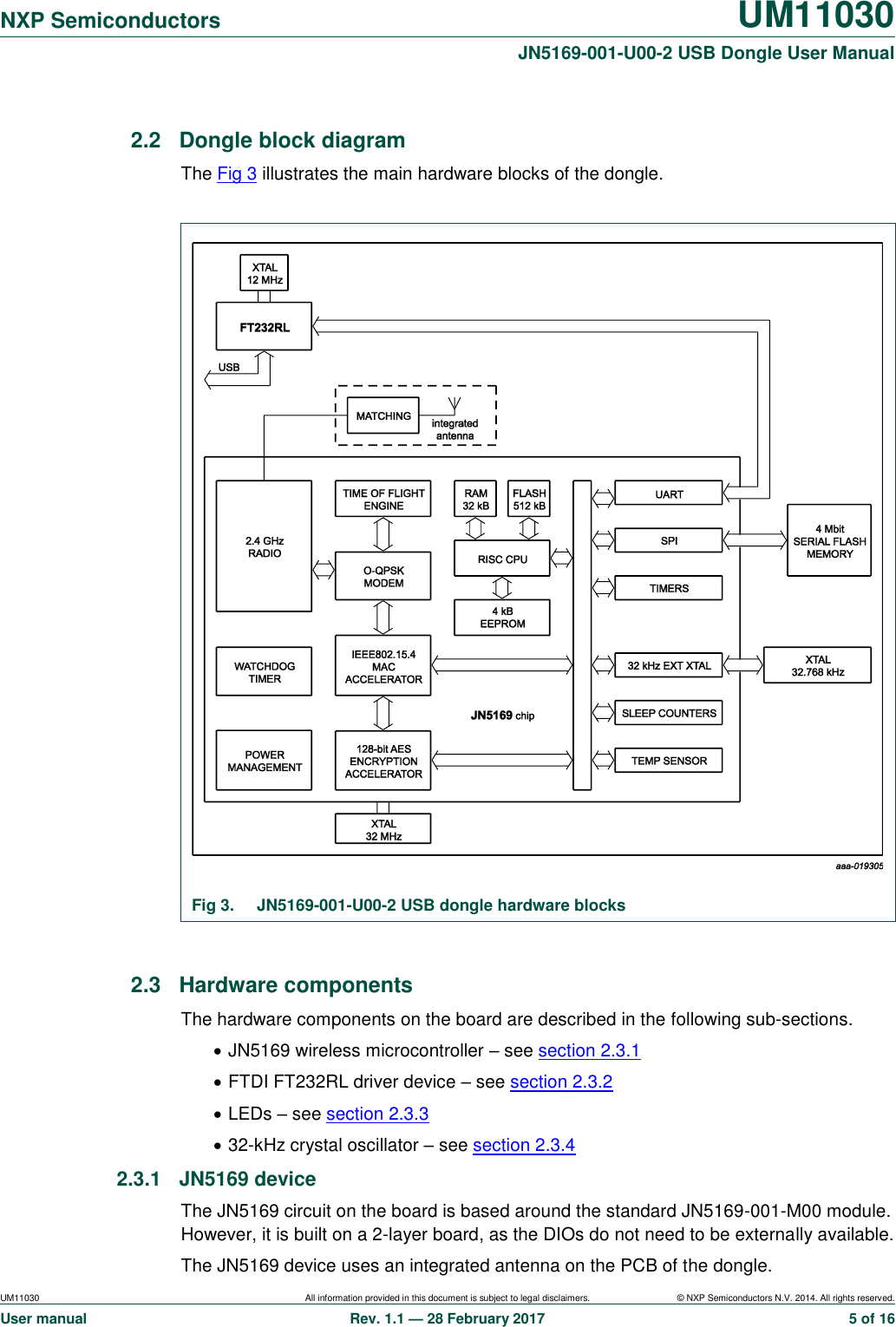
![NXP Semiconductors UM11030 JN5169-001-U00-2 USB Dongle User Manual UM11030 All information provided in this document is subject to legal disclaimers. © NXP Semiconductors N.V. 2014. All rights reserved. User manual Rev. 1.1 — 28 February 2017 12 of 16 5. Abbreviations Table 2. Abbreviations Acronym Description BOM Bill Of Materials DIO Digital Input/Output FCC Federal Communication Commission IC Industry Canada PCB Printed Circuit Board UART Universal Asynchronous Receiver/Transmitter USB Universal Serial Bus 6. References [1] JN5169 JN5169 Data Sheet [2] JN-UG-3087 JN516x Integrated Peripherals API User Guide [3] DR1198_JN5169_USB_Dongle_1V0b DR1198 USB dongle PCB files](https://usermanual.wiki/NXP-Semiconductors/JN5169U0V2.User-manual-rev-pdf/User-Guide-3298517-Page-12.png)