NXP Semiconductors OM12000 GSM/GPRS Module User Manual
NXP Semiconductors GSM/GPRS Module
User Manual

NXPBUAUTOMOTIVETELEMATICS
ATOP2.5GProject
Documentation
RafPeeters
OM12000(ATOP)HWuser
manual
InfoContent
Documenttypedocumentation
AuthorRafPeeters
AuthorRoleApplicationHW engineer
KeywordsATOP 2.5G,Teleboxmini

NXPSemiconductorsOM1200(ATOP)Project
©NXPN.V.2010Allrightsreserved2/27
Summary
1.Documentpurpose..................................................................................................3
Purpose...................................................................................................................................................3
Scope.......................................................................................................................................................3
Support...................................................................................................................................................3
History.....................................................................................................................................................3
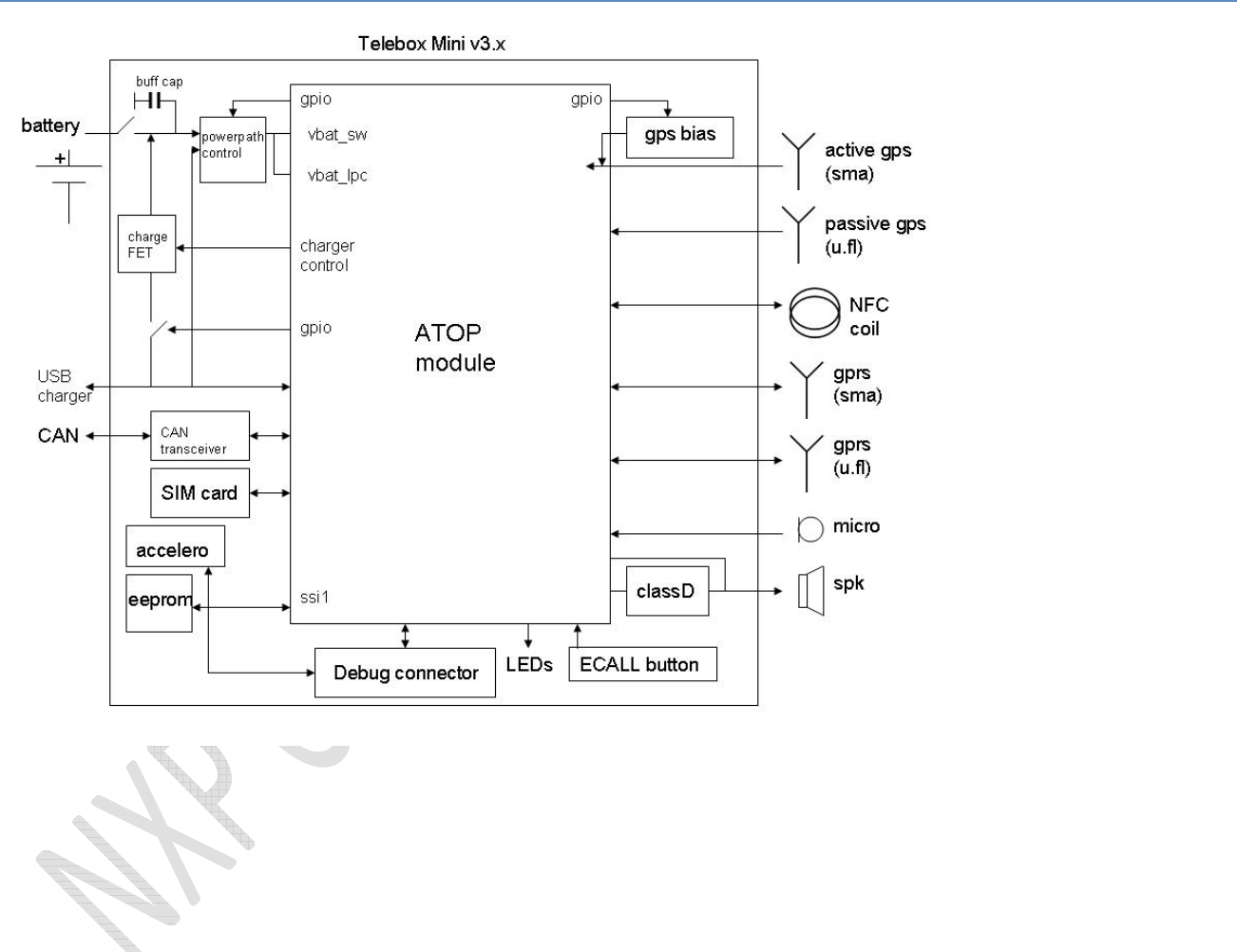
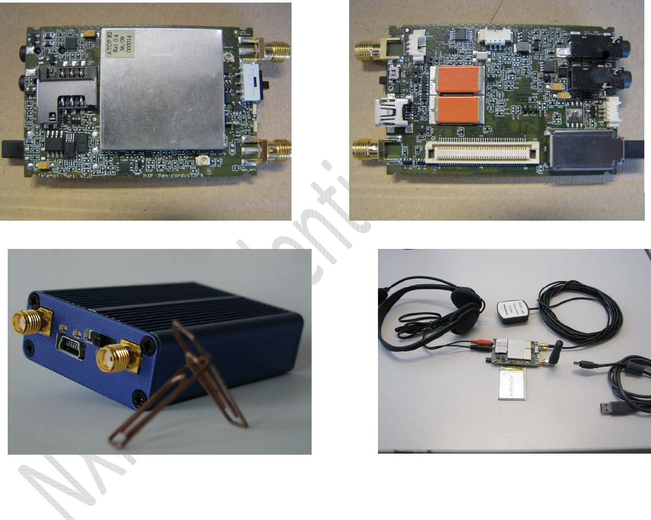
2.Blockdiagram&photos...........................................................................................4
3.Powersupply&batterycharger..............................................................................6
4.RFAntennaconnections........................................................................................10
GPRS......................................................................................................................................................10
GPS........................................................................................................................................................11
NFC........................................................................................................................................................12
5.SIMcard.................................................................................................................12
6.Clockmicrocontroller............................................................................................13
7.USB.........................................................................................................................14
8.PNXuartbuffer......................................................................................................15
9.CANtransceiver.....................................................................................................16
10.LED’sandbuttons..................................................................................................18
Resetswitch..........................................................................................................................................18
Ecallbutton...........................................................................................................................................18
LED’s......................................................................................................................................................18
11.Accelerometer/Eeprom/SSI1serialinterface....................................................20
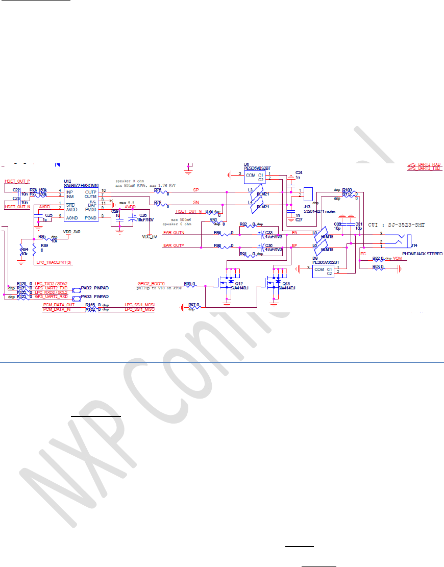
12.Audioconnections.................................................................................................22
Analogaudioin.....................................................................................................................................22
Analogaudioout...................................................................................................................................23
12.1.1Earphone...................................................................................................................23
12.1.2Speaker.....................................................................................................................24
13.Boardtechnology..................................................................................................25
14.CommentsUserManual........................................................................................27
15.FCCClassstatement.............................................................................................27

NXPSemiconductorsOM1200(ATOP)Project
©NXPN.V.2010Allrightsreserved3/27
1. Documentpurpose
Purpose
PurposeofthisdocumentistoprovideanuszermanualforOM12000by
describingTeleboxMiniHW,whichservesasreferenceHWplatformforNXPSW
developmentanddemowithincontextofATOP(OM12000)2.5Gproject.
Scope
Thisdocumentisintendedforall(HW/SWengineers,customers)whoneed
detailedunderstandingofTeleboxMiniv3.xHWimplementationandschematics.
Support
ForHWquestions,issueoranyproblem,pleasecontactcustomersupport.
History
TheTeleboxMinihasalreadysomehistory.
Thisnewversion3.xwhichaccommodatesB2ATOPversion,andalsosomemajor
changesareimplementedinthepowersupplycircuitry.
SincethisTeleboxMiniaimstobeaprototypeforSWdevelopmentanddemo,thereare
alotofjumperstuffoptionsfortestpurposewhichcustomersdon’tneedtocopy.The
defaultstuffoptionisindicatedintheschematicsbyadding“dnp”“donotplace”
markersoncomponentsnotstuffedbydefault.
Mainmechanicaldimensionsofthisdemopcbweredefinedinordertofitinthesmall
bluedemoboxGEPRO8023fromELPAC.
Asaresultlayoutdesignandcomponentchoicehadsomerestrictiontofulfilthetight
pcbarearestriction.
NXPSemiconductorsOM1200(ATOP)Project
©NXPN.V.2010Allrightsreserved4/27
2. Blockdiagram&photos
NXPSemiconductorsOM1200(ATOP)Project
©NXPN.V.2010Allrightsreserved5/27

NXPSemiconductorsOM1200(ATOP)Project
©NXPN.V.2010Allrightsreserved6/27
3. Powersupply&batterycharger
TheATOPSiPmodulebasicallyhas4powersupplyinputs:
V_BATT_SW:
suppliesbasebandPNX,frontendGPRSpoweramp,NFCpart,andGPSpart(viaonboard
LDO’scontrolledbyPNX)
V_BAT_RTC_PNX:
suppliesbasebandRTCfunction(ifnotconnectedexternally,internally
supplied/bypassedbyV_BATT)
V_BATT_LPC:
suppliesmicrocontrollerLPC(viaonboardLDO3V0,defaultON)
R67allowsforcurrentmeasurementonLPCdomain
V_BATT_RTC:
suppliesRTCfunctionofmicrocontrollerLPC
TheATOPalsohassomepowersupplyoutputs,generatedbybasebandPMUfunction:
V_SIM:
SIMcardinterface
V_PERM,VREF:
forreferenceonly,shouldnotbeexternallyloaded
V_IO(2V8):
forreferenceonly,shouldnotbeexternallyloaded(suppliesbasebanddigitalinterface
includingSSI,GPIO,DAI,JTAGanddebug)
PresenceofV_IOcanbedetectedonthemicrocontrollerLPCviaR53onGPIO
LPC_uart1_CTSP0.17
VDD_3V0:
ThisistheoutputvoltageoftheonboardLDOsupplyingthemicrocontrollerLPC.
Thissupplycanbeusedintheapplication,butwithlimitedcurrentloadsinceshared
withmicrocontrollerconsumption.
(TheLDO,LDS3985M30,isa3V/300mAoutputcurrentregulator.Theonboard
microcontrollerLPC2368hasmax125mAatmaximumactivityaccordingdatasheet)
NXPSemiconductorsOM1200(ATOP)Project
©NXPN.V.2010Allrightsreserved7/27
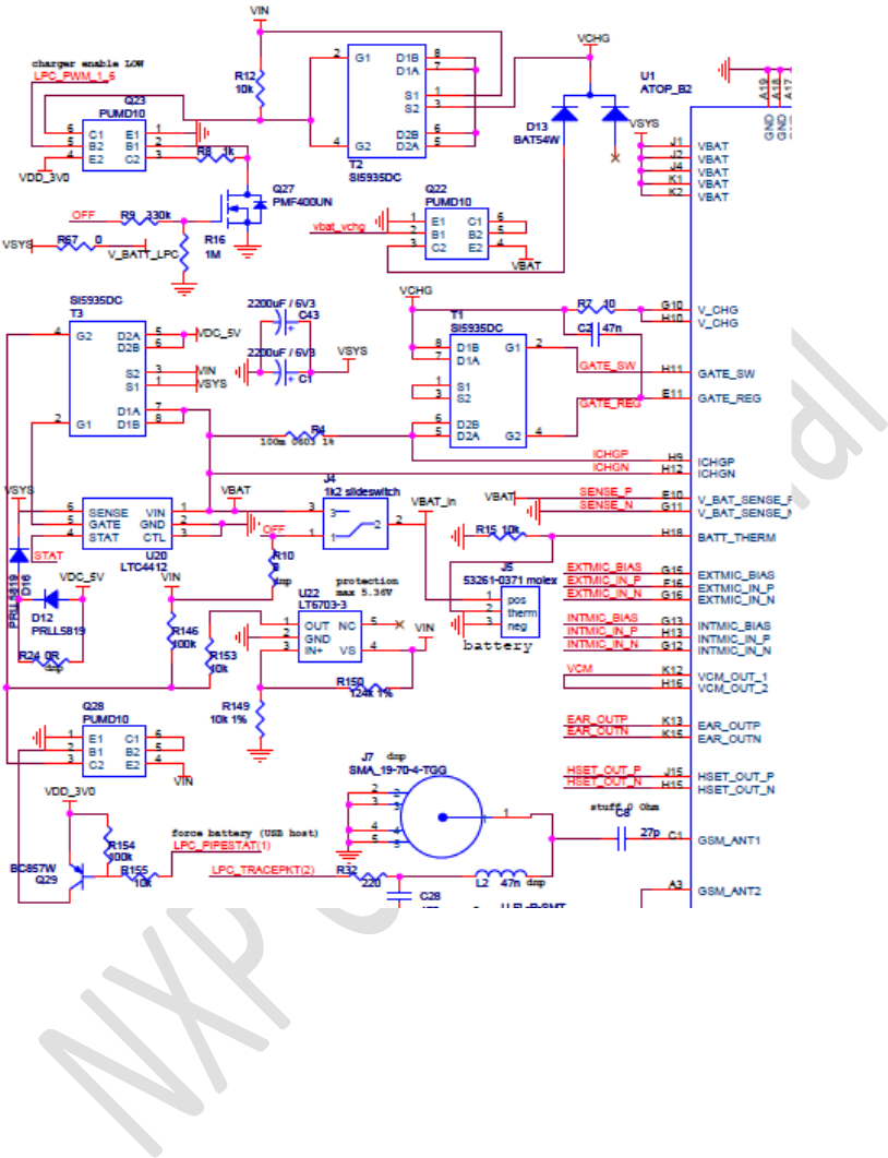
Figure1:extractofschematicsTeleboxMiniv3.0:powersupply&batterycharger
MainsupplyofthedesignisprovidedbytheLi‐polymerbattery,inthiscasePLF323450
fromVartaMicrobattery,typicalcapacity570mAh.(connectorJ5)
Sincethisbatterysamplehasnobuilt‐inNTCthermistor,R1510khasbeenaddedto
allowthebasebandPNXchargerfunctiondetectthebatterypresence.
SlideswitchJ4allowstotaldisconnectionofthebatteryfromthesystemtoavoid
possiblebatterydrain(ontheshelve)ormanuallyswitchON/OFFthesystembythe
user.
CapacitorsC1andC43provideextraenergybuffertocompensate,duringGPRS
transmissionslots,possiblebatteryvoltagedropduetoallkindofV_BATTresistance

NXPSemiconductorsOM1200(ATOP)Project
©NXPN.V.2010Allrightsreserved8/27
(totalpathfrombatteryuptosupplypinofGPRSfrontendpoweramp)likeconnection
wires,slideswitch,powerpathFET,pcbtraceandinternalbatteryimpedance.
Thevalueactuallyimplemented/neededoncustomerboardsdependsonrequirements
andimplementation.
ThebatterylevelcanbemeasuredviaresistivedividerR49/R50,connectedtotheADC
inputoftheATOPmicrocontrollerLPC.
PowerpathcontrollerLTC4412:
VSYSisthemainsupplyconnectedtoVBATpinsofATOPmodule.
LTC4412controlsthesourceforthisVSYS,2options:
‐ battery
‐ externalsupply/adaptor
Whicheverofthese2inputsupplieshasthehighestlevelwillbeconnectedtoVSYS.
TheexternalsupplyVINisattachedtothesystemviaeitherminiUSBconnectoror
solderpadPAD1.(stuffoptionviaR157/R159)
VBAToftheATOPhasamaximumlimitof4.8V.
OtherdevicesontheTeleboxMini(CAN,LPCVBUSandclassD)havealsomaximum
limitson5.5V.
Inordertofulfiltheselimitationsomeextracircuitryhasbeenadded:
a)DiodesD16andD12createsomevoltagedrop,whichwilldependonthecurrentto
VSYS,onit’sturndependentonapplication.
D12canbebypassedbyR24incasethesystemcurrentishighenough.Wetargetto
haveLTC4412switchedalwaysforVINpath,ifexternalsupplyispresent(forthiswe
needforworstcase,meaningwhenfullychargedbattery,minimum4.2VatSENSEpin
ofLTC4412)
b)Comparator/zenerU22willenablethepathVIN_to_VDC_5V(2ndFETofdualFETT3)
aslongasVINissmallerthen5.36V,sothatafterdiodevoltagedropVSYSislessthan
4.8V.Outputpin1ofU22willpulldownthegateandassuchenablethePFET.
InordertobeabletofulfilmaximumallowedcurrentdrainfromUSBhosts(USB_spec:
initiallyduringenumerationmax100mA…maximumcurrentnegotiableupto500mA)
dualbipolartransistorQ28(internalresistors)andQ29isadded.
Thisallows,inTeleboxMiniapplicationswereexternalsupplyisconnectedtoareal
USBhostbuswithcurrentlimitation,andVINR157optionisstuffed,theLPCFWto
controlandforcethepowerpathcontrollerLTC4412toconnectVSYStobatterysource,

NXPSemiconductorsOM1200(ATOP)Project
©NXPN.V.2010Allrightsreserved9/27
incasesystemcurrentisexpectedtoincreaseabovethenegotiatedallowedmaxUSB
hostcurrentdrain.
ThePNPpartofQ28willshorttheGate_SourceresistorR146ofVIN_to_VDC_5VFET
T3_2whentheGPIOLPC_PIPESTAT(1)P2.2ispulledLOW.
DefaultafterresetofLPC(input/pullupmodeGPIO)this“disable”functionisOFF,in
USBapplicationsthesystemstartupcurrentshouldbelimitedto100mA…
Chargerfunction:
TheATOPbasebandPNXhasanintegratedchargerfunctionwhichneedsonlysome
externalFETSi5935DC,T1(dualFETpackageofwhichoneFETischargeON/OFFcontrol
withbodydiodesuchtoavoidanyreversecurrentwhenOFF,theotherFETisanalog
controlledforchargecurrentlevelsetting)andseriesresistorR4(100mOhm)to
measurechargecurrent.
Importantremark:
‐ makesurethechargecurrentamplitude,programmedinbasebandflash
memory,iscompatiblewithmaximumallowedchargecurrentspecifiedinthe
datasheetoftheappliedbattery!
‐ InordertoavoidoverheatingthechargerdualFETT1(dissipationof2ndFETis
equaltoproduct(deltaVIN–VBAT)*I_chargelimitVINoftheexternalattached
chargeradaptorto5V!
(someprecautions(coolingcopperarea)havebeentakentoreducethethermal
resistanceRth_jaofT1,butphysicalpcbarealimitationofTeleboxMinilimits
coolingefficiency)
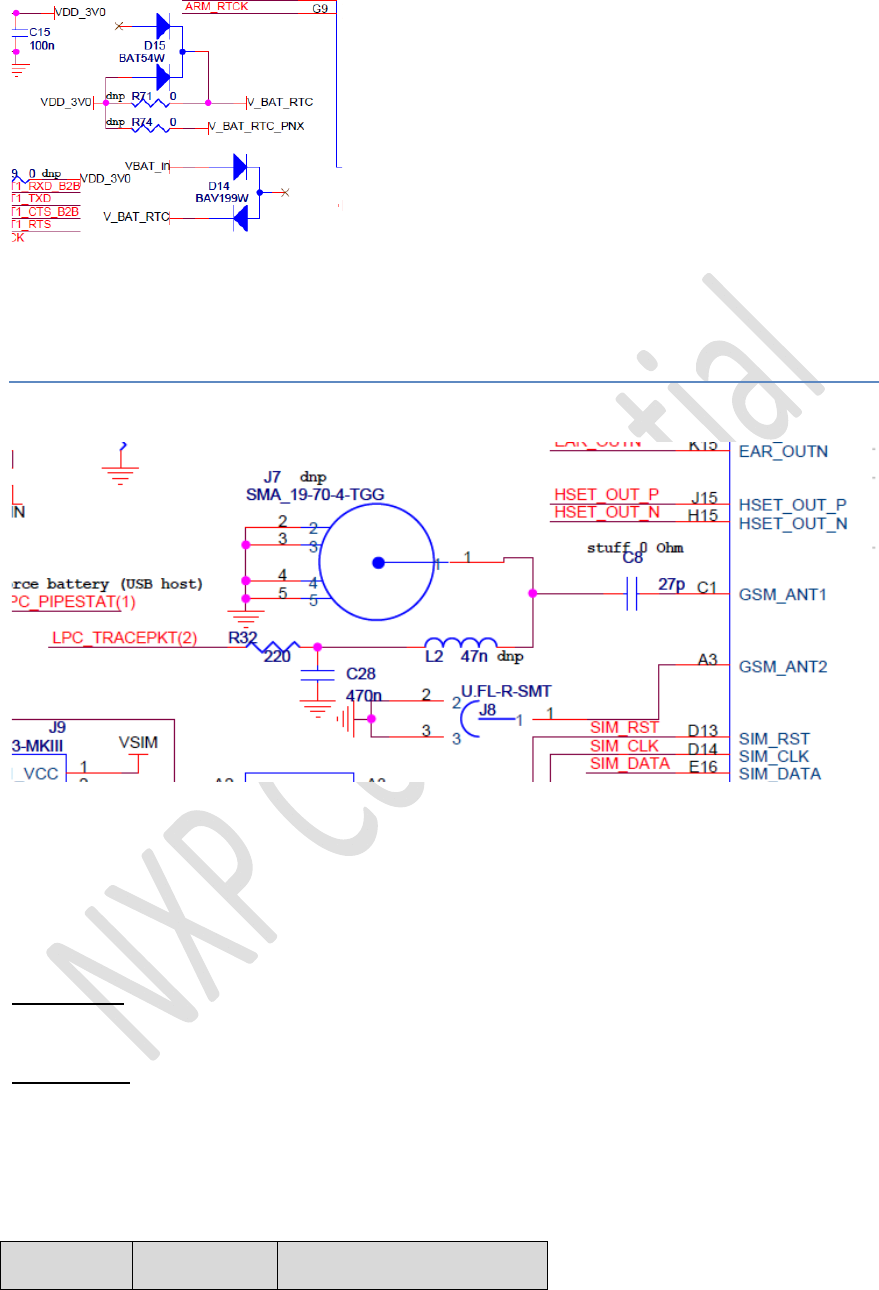
RTCbackupfrombattery:
InordertokeepRTCofLPCalivewhenmainsupplyisoff(externalsupplydisconnected
andslideswitchJ4inOFFstate)theLPCRTCcircuitrywillbekeptsuppliedbyVBAT_in
(=directlyconnectedtobattery)viadual_seriesdiodeD14(D15preventsreverse
currenttoVDD_3V0).Seenextstuffingoption:
NXPSemiconductorsOM1200(ATOP)Project
©NXPN.V.2010Allrightsreserved10/27
4. RFAntennaconnections
GPRS
OnboardtheATOPmodulethereisanantennaRFswitchinfrontofthepoweramp.The
TeleboxMinioffers2waysforconnectinga50ohmGPRSquad‐bandantenna.
GSM_ANT1:SMAjackJ7(SMA19‐70‐4‐TGGMulticomp)
R
GSM_ANT2:UFLjackJ8(U.FL‐R‐SMTHirose)
Thispathismeanttoaccommodatesomeinternalgprsantennainsidetheproduct
housingbymeansof50ohmU.FLcableassembly.
MicrocontrollerGPIO‘GSM_ANT_SWITCH’P1.0selectseitherofthepaths:
GPIOP1.0GSM_ANT1GSM_ANT2
NXPSemiconductorsOM1200(ATOP)Project
©NXPN.V.2010Allrightsreserved11/27
1OFFON
0ONOFF
Remark:fordevelopmentthisquadbandGPRSantennaisusedonGSM_ANT1SMA:
MC0114015‐FME‐BU‐W,manufacturedMC‐Technologieshttp://www.mc‐
technologies.net/en/wireless_modules/antennen‐und‐zubehoer/index.php
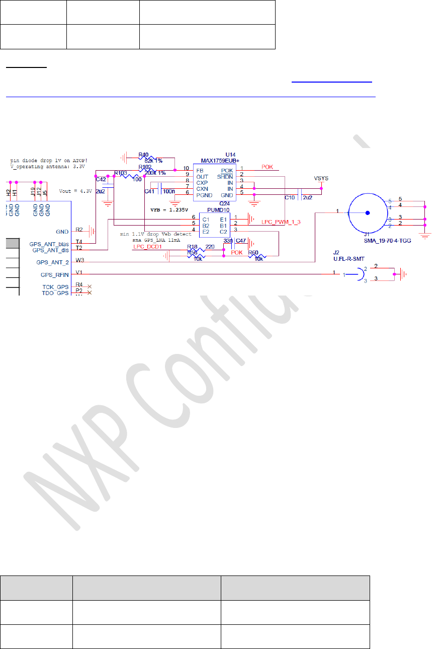
GPS
TheATOPmodulehasanonboardLNAwhichaccommodatesforapassiveGPSantenna.
ThisinputoftheLNAisconnectedtotheU.FLconnectorJ2.
ThispathismeanttoaccommodatesomeinternalGPSantennainsideamechanical
prototypehousingbymeansof50ohmU.FLcableassembly.
InordertoconnectsomeexternalactiveGPSantenna,connectorJ1accomodatesfora
(longer)50ohmSMAcable.Inthisoption,weuseinputGPS_ANT_2whichbypassesthe
onboardLNA.TheonboardLNAisdisabledbypullingitsinputlowviathenpnpartof
Q24(controlledbyGPIOLPC_PWM_1_3P3.26).
ThebiassupplyfortheactiveantennaisprovidedviathechargepumpU14MAX1759,
configuredforVout=4.3V.SincethereisaPINdiodeinthepathwithdropofabout1V,
thisleavesabout3.3Vfortheantennasupply.Toaccommodateforothersupply
requirementsR102/R40canbechangedaccordingly.
GPIOP3.26willexclusivelyactivateeithertheonboardLNAorthechargepumpbias
supplyaccordingfollowingtruthtable:
GPIOP3.26InternalLNA/passiveGPSBiassupply/activeGPS
1OFFON
0ONOFF
NXPSemiconductorsOM1200(ATOP)Project
©NXPN.V.2010Allrightsreserved12/27
Remark:fordevelopmentfollowingactiveGPSpatchantennaisused:
GAACZ‐A,,5mcable,3‐5V,manufacturedbyActiveRobotsLtd.http://www.active‐
robots.co.uk/active‐gps‐antenna‐p‐552.html
NFC
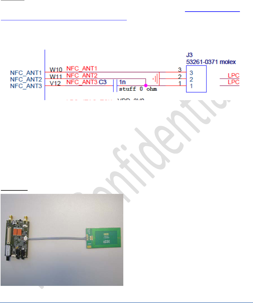
TheATOPmodulehasaNFCreaderfunctiononboard.
ConnectorJ3,Molex53261‐0371,accommodatesfortheNFCcoil.
StuffoptionC3isforRFtest,fornormaluseitisstuffedwith0ohmjumper.
ThecableconnectingtheTeleboxMiniwiththeantennacoilshouldbemaximum10cm.
Remark:fordevelopmentaNXPreferencecoilsdesignisused.
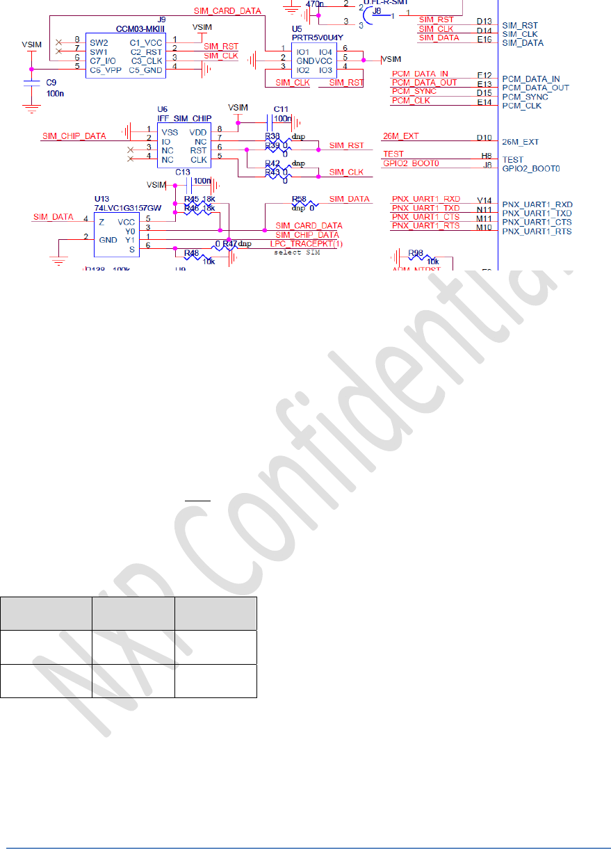
5. SIMcard
NXPSemiconductorsOM1200(ATOP)Project
©NXPN.V.2010Allrightsreserved13/27
ConnectorJ9,CCM03‐MK3fromC&K,accommodatesforSIMcardinsertion.
U5,PRTR5V0U4YNXP,providesESDprotection.
TheTeleboxMinihasastuffoptiontoaccommodateapcbsolderedSIMchip(U6).
(R38/R42allowforpossiblefuturepinchange)
InordertoswitchaccessbetweenbothSIMcardoptions,analogmuxU13multiplexes
theSIMdatalinesbyGPIOcontrolLPC_tracepkt(1)P2.6.
DefaultstuffoptionR48/R47selectsconnectorJ9.
R58allowsbypass/i.e.nottostuffthemux.
IfR47and/orU6wouldbestuffedfollowingtruthtablewouldhold:
GPIOP2.6SIMcardSIMchip
1OFFON
0ONOFF
6. Clockmicrocontroller
NXPSemiconductorsOM1200(ATOP)Project
©NXPN.V.2010Allrightsreserved14/27
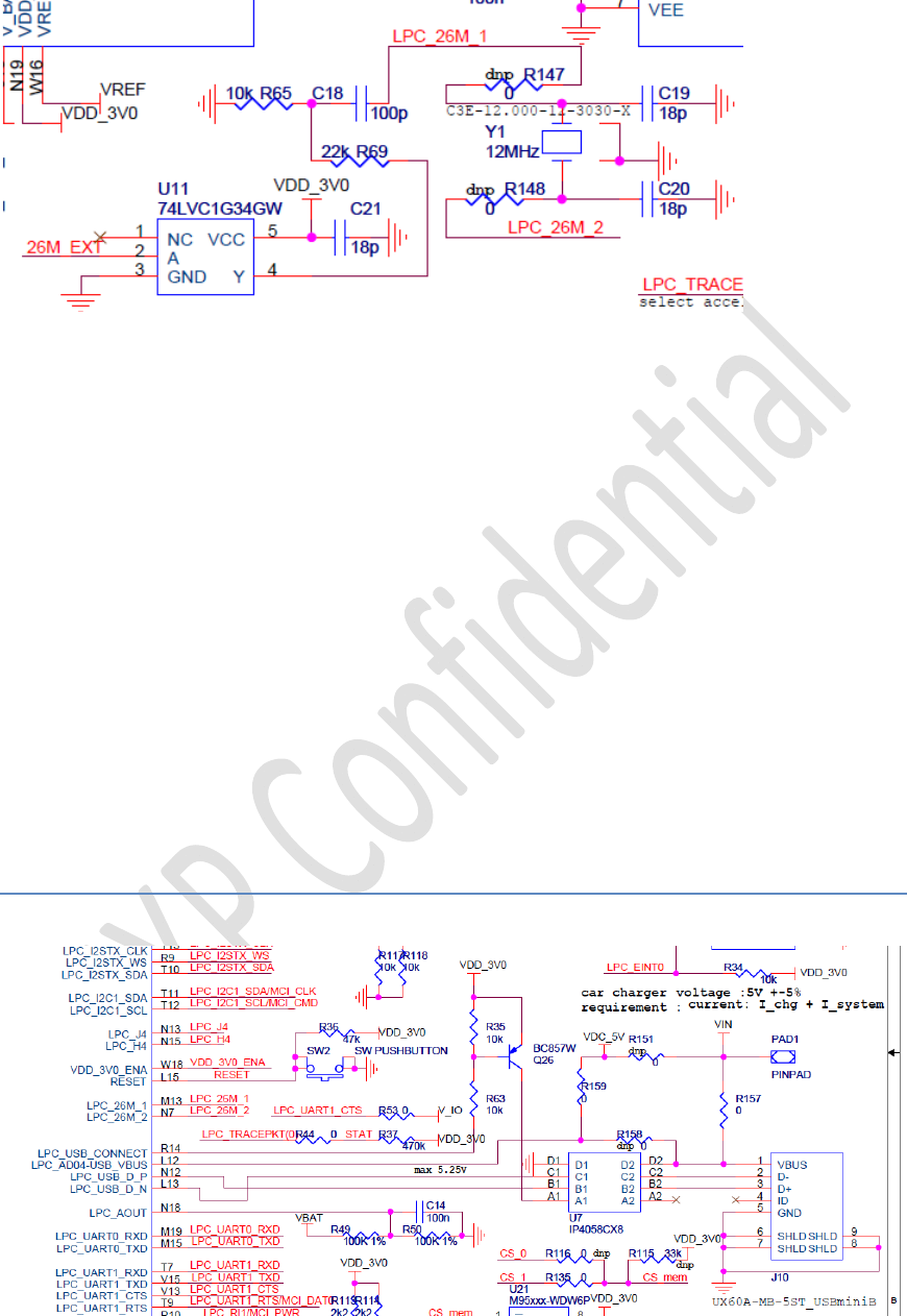
Thereare2optionsontheTeleboxMinitosourceanexternalclocktothe
microcontrollerLPC.26M_EXTisa26MHzoutputclockfromtheATOPbaseband.Buffer
U11bufferstheclocksignal,whileR69/R65resistivedividermatchesmaxvoltageswing
specifiedbytheLPC.
AnotheroptionforsourcingtheLPCexternalclockisusingthe12MHzcrystalY1with
theLPCowninternalmainoscillator.(requiredforUSBorHSCANfeature
implementationwithmorestringentclockjitterrequirements)
Forthisoption:stuffR147/R148andremoveACcouplingC18.
7. USB
NXPSemiconductorsOM1200(ATOP)Project
©NXPN.V.2010Allrightsreserved15/27
TheATOPmicrocontrollerLPChasaUSB2.0fullspeeddevicecontrolleronboardwhich
canbeaccessedbymini‐BUSBconnectorJ10.
U7providesESDprotectionwithintegratedpi‐typefilter,33ohmseriesresistorsand1k5
pullupresistor(connectedtoQ26fordelayeddevicedetectsignallingoption).
AlsothisUSBconnectorisusedasbatterychargerinput.
Pleaserefertochapter3‘powersupplyandbatterycharger’,regardingstuffoptions
R157/R158/R159andmaximumUSBhostdraincurrentlimitations!
ItispossibletowakeupthemicrocontrollerLPCfrompowerdownmodebyevent
detectiononanyGPIOfromport0or2.ToallowwakeupeventfromUSBcharger
cableinsertdetection,R44connectsLTC4412‘STAT’signaltoGPIOLPC_tracepkt(0)
P2.5.WhenUSB_miniBconnectorisusedaschargerinput,STATwillbepulledLOW
whenchargerispresent.
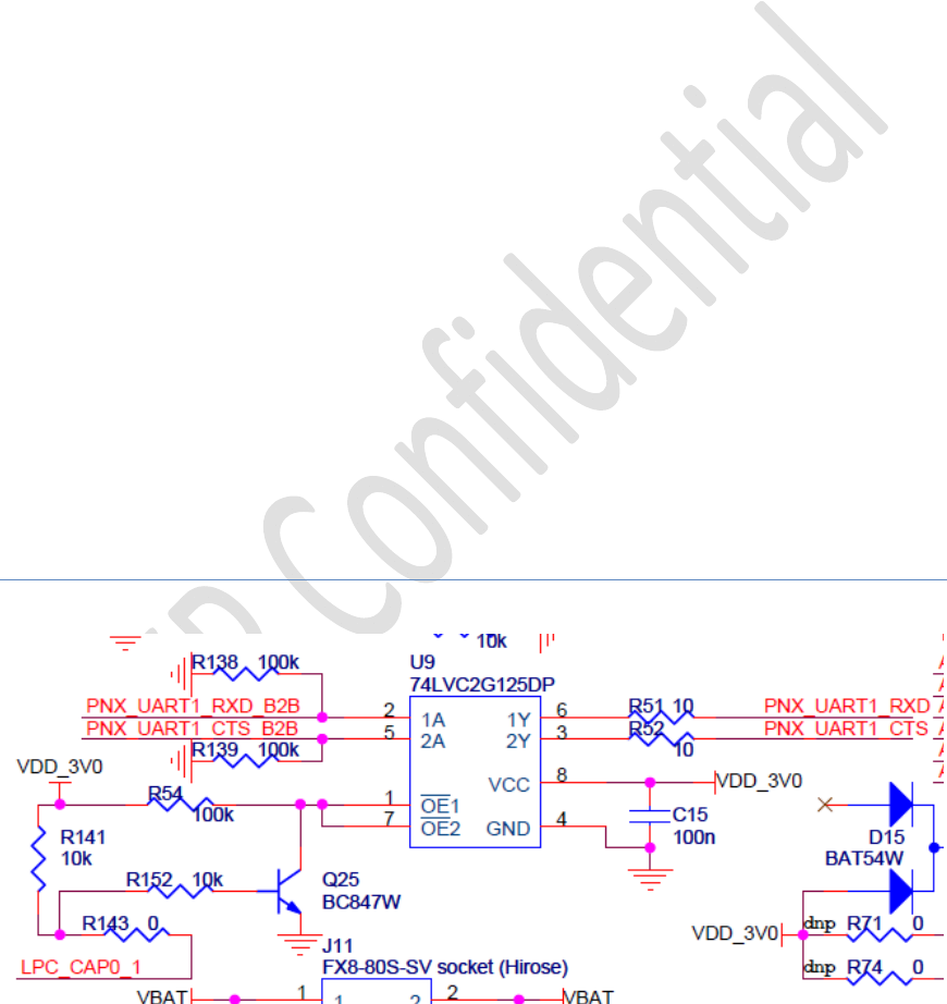
8. PNXuartbuffer

NXPSemiconductorsOM1200(ATOP)Project
©NXPN.V.2010Allrightsreserved16/27
Inordertoproperlystartupthebaseband,thereshouldnotbeanyparasiticsupply
currentpresentonthePNXpinsbeforesending“powerON”commandviaLPCSW.So
anyinputcurrentshouldbeavoidedforallPNXIOpins(pcm,analog,…)
InordertoavoidRS232transceiveronthePNXuartlinescouldunintentionallysupply
current,abufferU9hasbeeninsertedontheTeleboxMinitoallowpropercontrolby
themicrocontrollerLPCviaGPIOLPC_CAP0_1P1.27.
GPIOP1.27PNXuart
1Enabled
0Disabled
9. CANtransceiver
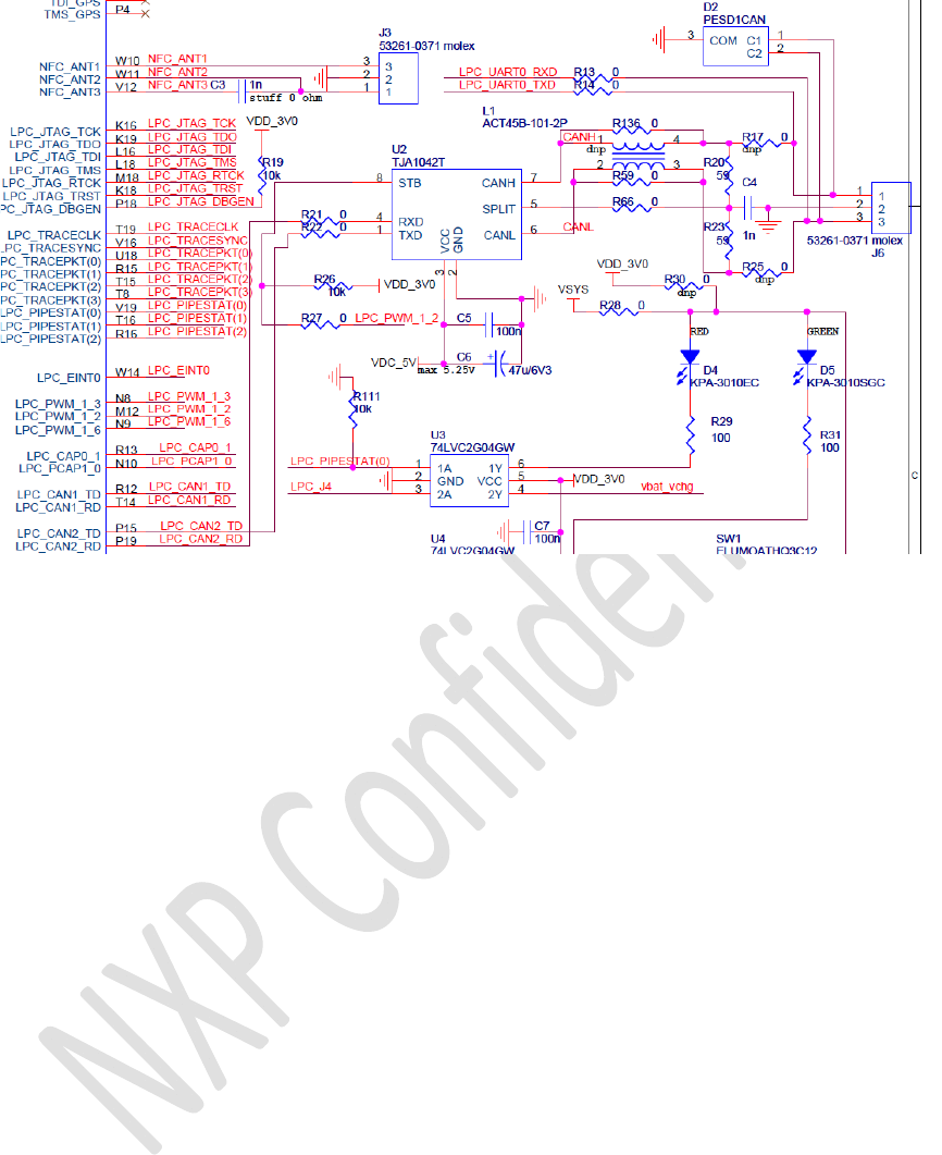
NXPSemiconductorsOM1200(ATOP)Project
©NXPN.V.2010Allrightsreserved17/27
TheATOPmicrocontrollerLPChas2CANcontrollersonboard(CAN2.0,1Mbit/s).
TeleboxMiniaccommodatesoneCANcontrollerwithahighspeedCANtransceiver,U2
TJA1042T,withsomecommonmodechokeoptionandESDprotection.
TheCANinterfaceisonlyfunctionalwhenVDC_5Visappliedtothesystem(eithervia
USBorviaexternalpowersupply).Whennotpowered,thetransceiverhasidealpassive
behaviour,notdisturbingeventuallyconnectedCANbus.
GPIOLPC_PWM_1_2P3.25cancontrolstandbystatusofthetransceiver.
Instandbymodethereispossibilityforremotewake‐upcapabilityviatheCANbus.
BesidesCANinterface,the3pJ6Molex53261‐0371connectorcanalsoaccommodate
forconnectiontothemicrocontrollerLPCuart0port.
ThiswouldallowflashingnewcodetoLPCfromoutsidethebluemechanicalbox
(EINT_0,neededtobringLPCinflashmode,isavailableattheilluminatedpushbutton
SW1)
StuffoptionJ6connection:
‐R13/R14:LPC_uart0
‐R17/R25:CAN2
NXPSemiconductorsOM1200(ATOP)Project
©NXPN.V.2010Allrightsreserved18/27
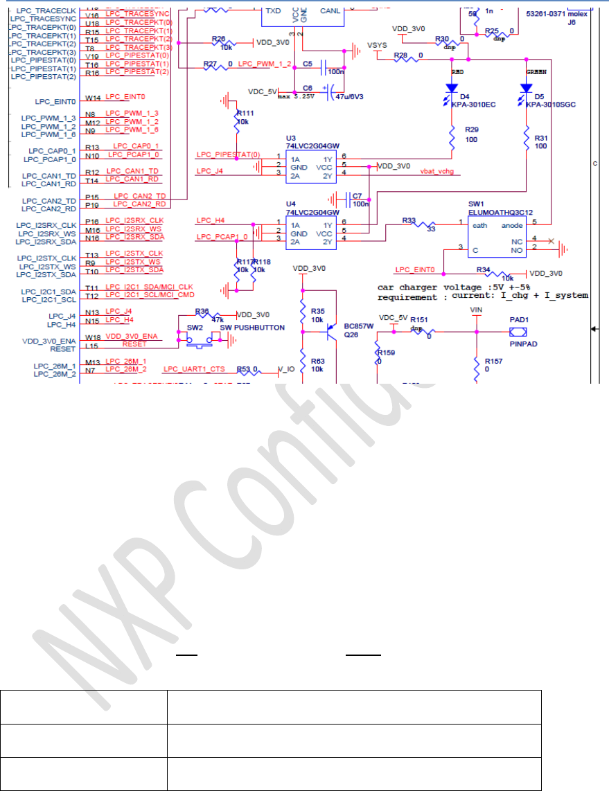
10. LED’sandbuttons
Resetswitch
TactswitchSW2onthesideoftheboardallowsmanualresettingthesystem.
Ecallbutton
IlluminatedpushbuttonSW1isintendedasmanualinputfromtheusertoinitiatean
Ecall.GPIOLPC_EINT0P2.10islowwhenthebuttonispushed.Sinceitispartofport2,
thisbuttoniscapabletowakeupapowereddownsystem.Thebuttonalsohasan
integratedredLEDtoallowuserinteraction.
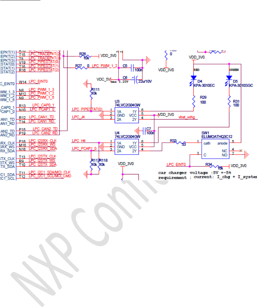
LED’s
1redLEDD4and1green/redLEDD5areavailableforuserinterface.
InallcasestheLED’sareONwhentheGPIOissetHIGH(U3/U4arebufferinginvertors)
FollowingtableprovidesanoverviewofGPIOconnectionstotheLED’s
RedLEDD4GPIOP2.1
GreenLEDD5GPIOP1.18
RedEcallbuttonLEDGPIOP1.28
NXPSemiconductorsOM1200(ATOP)Project
©NXPN.V.2010Allrightsreserved19/27
V3.2changes:
RemovedstuffoptionR28/R30forsupplyofLED’s.
SinceVsyswillbehigherthen3V,U3andU4arenotabletodisableLEDcurrent…
Followingupdatedschematics:
NXPSemiconductorsOM1200(ATOP)Project
©NXPN.V.2010Allrightsreserved20/27
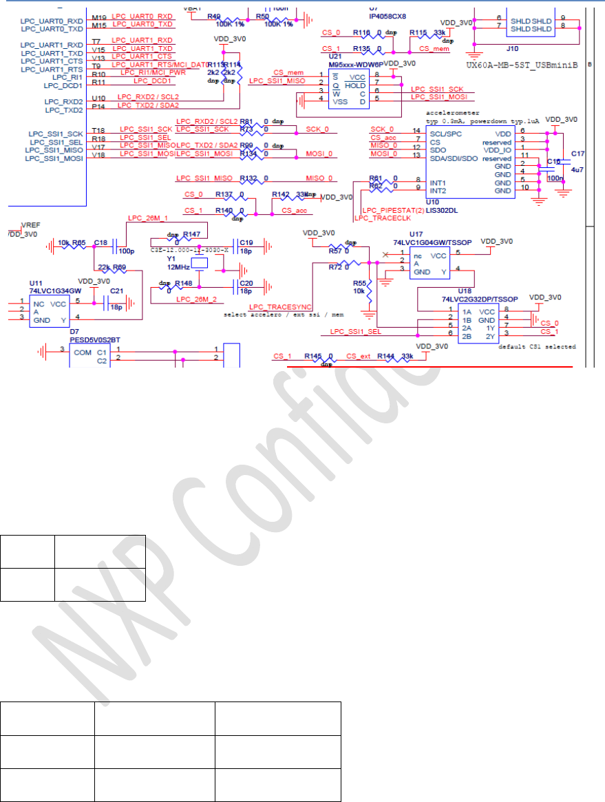
11. Accelerometer/Eeprom/SSI1serialinterface
OnesynchronousserialinterfaceSSI1ofATOPmicrocontrollerLPCisavailablefor
externaldevice/userapplication(forinstancetoconnectsomeserialdisplayviathe
debugconnectorJ11)
OnboardtheTeleboxMinia3DdigitaloutputaccelerometerU10LIS302DL(ST)is
stuffedandconnectedwiththisSSI1portaswellasaSPIEEPROMU21M95xxx.
Theaccelerometerhas2configurableinterruptoutputlines,thatallowwakeupofa
powereddownATOPsystem(evenwhenacceleroitselfinpowerdownmode).
INT1GPIOP2.0
INT2GPIOP2.3
GPIOLPC_tracesyncP2.4selectswhichdevice(CS0orCS1)isconnectedwithSSI1port.
TheCSlineismuxedbythe2‐inputORgateU18(invertorU17eitherselectsCS_0or
CS_1)
GPIOP2.4CS1CS0
0OFFON
1ONOFF
NXPSemiconductorsOM1200(ATOP)Project
©NXPN.V.2010Allrightsreserved21/27
Viaresistorsstuffoptionsdifferentcombinationscanbeimplementedforconnectionto
CS0orCS1ofSSI1interfacechipselect:
Defaultstuffing:
‐ Accelero(CS_acc):CS0
‐ Eeprom(CS_mem):CS1
‐ Externalviadebugconnector(CS_ext):notconnected
Anotherstuffoption(viaR81/R99)allowsforconnectingtheacceleroinI2Cmode(this
waymakingSSI1alsoavailablefordebuginterfaceconnectoratthesametime)
Default:
AcceleroinSPImode
V3.2changes:
a)
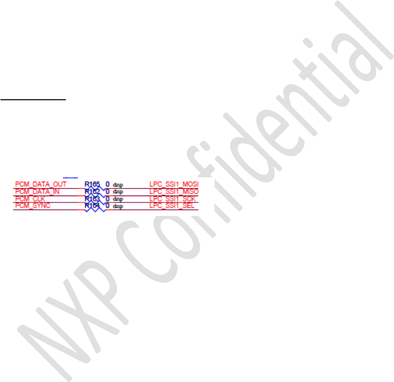
InordertoallowlinkingbasebandBB_PCMaudiooutputwithSSI1channelofthe
microcontroller,aspecialstuffingoptionhasbeenadded.(R162/163/164/165)
Sinceinthisusecase,basebandPCMneedstobebusmaster,LPCshouldbeconfigured
asslaveSSI1.
InordertoavoidpossibleconflictswiththeotherslaveSSI1peripherals(chipselectsCS0
andCS1,SPI_memoryU21CS_memandSPI_acceleroU10CS_acc),bothCSshouldbe
disconnectedfromthebus:
RemoveR116/R135,stuffR115(memory)
RemoveR137/R140,stuffR142(accelero)
Alsodon’tuseexternalCS_ext,don’tstuffR145(default)
NXPSemiconductorsOM1200(ATOP)Project
©NXPN.V.2010Allrightsreserved22/27
12. Audioconnections
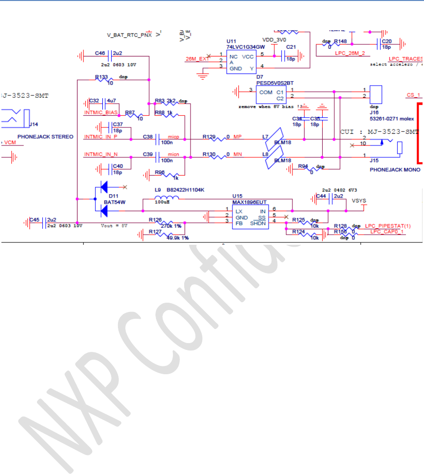
Analogaudioin
TheATOPbasebandPNXhastwomicrophoneinputports:
EXTMIC_BIAS/EXTMIC_IN_P/EXTMIC_IN_N:notconnected
INTMIC_BIAS/INTMIC_IN_P/INTMIC_IN_N:implementedonTeleboxMiniwith
necessarypassivecomponentsandprotection
Defaultstuffoptionprovidesforthedifferentialconnectionmode.ConnectorJ15
accomodatesforastandard3.5mmmonoplugelectretmicrophone.Incaseasmall
electretmicrophonewouldbeintegratedinthemechanicalhousing,provisionhasbeen
madeforasmaller2pconnectorJ16Molex53261‐0271.(J16<>3.5mmJ15/J14canonly
exclusivelybestuffed!)
Incasehigherbiassupplyisneeded(likeforinstanceautomotiveAKGQ400series
preamplifiedmousemicrophone),anextraDCDCconvertorisaddedU15MAX1896,
defaultconfiguredfor8V.InthiscaseplaceR133andremoveR87(alsoremove
protectiondiodeD7sinceitwillclipat5V)
EnablepinofU15canbeSWcontrolledvia2possibleGPIO’s,P2.2possiblyconflicting
with‘USBforcebatterysupply’,orP1.27possiblyconflictingwithPNX_uartbuffer
control.ToenabletheDCDC,settheGPIOHIGH.DefaultthisSWcontrolisnotstuffed.
Incasevoltageswingoutputofpreamplifiedmicrowouldbetoolarge,resistors
R129/R130couldberesistivedivider.
NXPSemiconductorsOM1200(ATOP)Project
©NXPN.V.2010Allrightsreserved23/27
V3.2changes:
a)
TomakeU15stablewhenloaded,R161/C49arerequired.
Followingupdatedschematics:
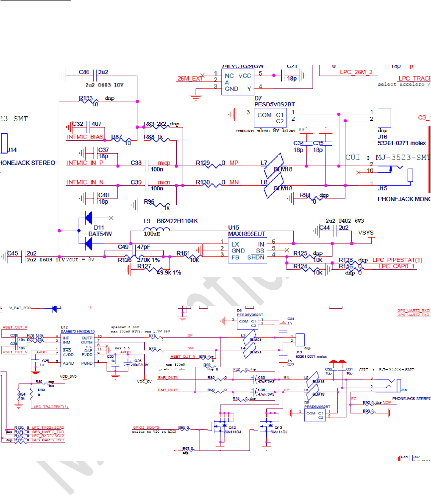
Analogaudioout
TheATOPbasebandPNXprovidessomeanalogoutputchannels.
12.1.1 Earphone
TeleboxMinihasimplementedearphoneoutputchannelEAR_OUTN/EAR_OUTPwith
necessarypassivecomponentsandprotection.
Twostuffoptionsareimplemented:
‐ audioreferencedtocommonmodeVCM(avoidslargecapacitors,butcouldbe
problemwhenconnectingtoexternaldevicewithinputreferencetoGNDlevel)
‐ AC‐coupledoutputs,referenceGND

NXPSemiconductorsOM1200(ATOP)Project
©NXPN.V.2010Allrightsreserved24/27
Inthelattercase,someannoyingpoweron‘plop’canbeheared.Thiscanbeavoidedby
keepingtheoutputstoGNDlevelduringpoweron(Q12andQ13aresmallfootprint,
andhaveverylowONresistancetominimizeploplevel).Controlofthe‘antiplop’
transistorsisdonebybasebandGPIO2_BOOT0(haspullupresistoronATOPmodule)
ThecommonmodeoptionshouldbepreferredsincethebodydiodesofQ12/Q13will
createsomeharmonicdistortionatlargeroutputswing.Neverthelesstheotheroption
isstuffedbydefaulttoavoidpossibleunintentionallyconflictVCM<>GND.
ConnectorJ14providesaccommodationforastandard3.5mmstereoplug.
12.1.2 Speaker
TheATOPbasebandPNXprovidesoptiontosourcean8ohmspeakerwithmax500mW
outputpower.Forthis:removeR86/R90/R75/R87R78andstuffR79/R80.
Ifthispowerlevelisnotsufficientfortheapplication,TeleboxMiniprovideswithan
externalclassDaudioamplifierSA58672fromNXP,whichcouldprovideupto
1.7W/8ohmwhensuppliedfromVDC_5V.ClassDfeatureonlyavailablewhenexternal
supplyconnected!
TheamplifierenablepincanbeSWcontrolledbyGPIOLPC_tracepkt(3)P2.8,setHIGH
toenable.
SpeakerconnectorJ13:2pMolex53261‐0721.
NXPSemiconductorsOM1200(ATOP)Project
©NXPN.V.2010Allrightsreserved25/27
V3.2changes:
a)
Inordertohavespeakeroutputaccessibleonthe3.5mmjackconnectorJ14(=earphone
outputdefault)somestuffingoptionisadded:R100/R112.
Forthisusecasefollowingstuffingshouldbeapplied:
RemoveL5/L6/R92/R93
StuffR100/R112
Followingupdatedschematics:
13. Boardtechnology
TheTeleboxMiniistargetedtobeaHWplatformforSWdevelopmentanddemo
vehicle.Itisaprototype,notintendedtobemassproductionready.
Assuchitisnotadvisedtorunverylargequantitybatches,therewillbeyieldissues.
Alsopossiblynotfullyoptimizedforcostandassemblymachinelimitations.
Maximumefforthasbeendonetokeeptheoutlinemechanicaldimensionsassmallas
possible,integratingallfeaturesdescribedaboveandstillfittingthebluedemobox
GEPRO8023.
EDAtoolbeingusedisORCADschematicCaptureandLayoutv10.5.0.
DRC(designrulecheck)globalspacingsettingsaresetat70um.
StandardVIAdimensionsusedare(padsize0.4mm/drillhole0.2mm)diameter.
Outlinepcbdimensions:65mmx42.8mm
(4halve‐circlecut‐outs,formechanicalspacerwith2mmscrews:inlongsideofthepcb
athorizontalcoordinatesx=3andx=62andbothy=0and42.8)
NXPSemiconductorsOM1200(ATOP)Project
©NXPN.V.2010Allrightsreserved26/27
Pcbthickness:1.2mm
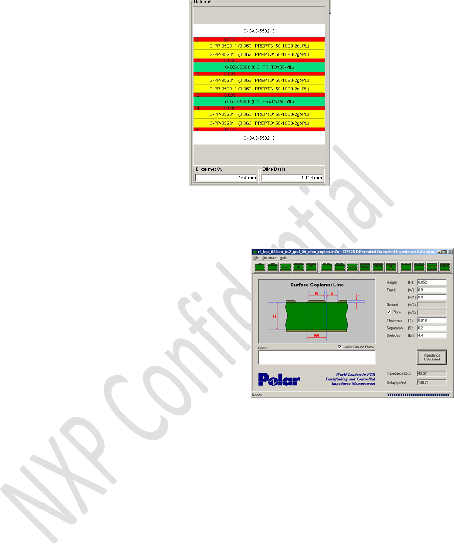
Numberoflayers:6:
1.top
2.gnd
3.pwr
4.in1
5.in2(=gnd2)
6.bot
Stackbuilduptechnologyused:
Regardingtheimpedancecontrolfor50ohmRFantennatraceslocatedonlayer1.top,
layer5.in2isusedasreferencegroundinordertokeepRFtracewideenoughtolower
losses(insteadofusinglayer2.gnd).Allotherlayersinbetweenhavebeenkeptfreeof
tracesandcopperaroundthetransmissionlines.
Tracewidth:0.9mm
GNDclearancecopperfill:0.2mm
sumthicknessoflayersbuildup:0.852mm
Er=4.4
copperthickness18um>>>resultsinabout50ohm:

NXPSemiconductorsOM1200(ATOP)Project
©NXPN.V.2010Allrightsreserved27/27
14. CommentsUserManual
Thisdevicecomplieswithpart15oftheFCCRules.Operationissubjecttothe
followingtwoconditions:
(1)Thisdevicemaynotcauseharmfulinterference,and
(2)thisdevicemustacceptanyinterferencereceived,includinginterferencethatmay
causeundesiredoperation.
TheFCCrequirestheusertobenotifiedthatanychangesormodificationsmadetothis
devicethatarenotexpresslyapprovedbyNXPSemicondcutors,couldvoidtheuser's
authoritytooperatetheequipment
15. FCCClassstatement
ThisequipmenthasbeentestedandfoundtocomplywiththelimitsforaClassBdigital
device,pursuanttoPart15oftheFCCRules.Theselimitsaredesignedtoprovide
reasonableprotectionagainstharmfulinterferenceinaresidentialinstallation.This
equipmentgeneratesusesandcanradiateradiofrequencyenergyand,ifnotinstalled
andusedinaccordancewiththeinstructions,maycauseharmfulinterferencetoradio
communications.However,wecannotguaranteethatinterferencewillnotoccurina
particularinstallation.Ifthisequipmentdoescauseharmfulinterferencetoradioor
televisionreception,whichcanbedeterminedbyturningtheequipmentoffandon,the
userisencouragedtotrytocorrecttheinterferencebyoneormoreofthefollowing
measures:
•Reorientorrelocatethereceivingantenna.
•Increasetheseparationbetweentheequipmentandreceiver.
•Connecttheequipmentintoanoutletonacircuitdifferentfromthattowhichthe
receiverisconnected.
•Consultthedealeroranexperiencedradioortelevisiontechnicianforhelp.