Napco Security Systems 2WAYUNIVKF 2-Way Universal LCD Keyfob User Manual 2WAY UNIVKF WI1024J 19 INST PDF pub
Napco Security Systems Inc 2-Way Universal LCD Keyfob 2WAY UNIVKF WI1024J 19 INST PDF pub
UserManual.wiki
>
Napco Security Systems
>
2WAYUNIVKF User Manual
Users Manual
Navigation menu
Upload a User Manual
Namespaces
Wiki Guide
HTML
PDF
Info
Views
User Manual
Discussion / Help
Navigation
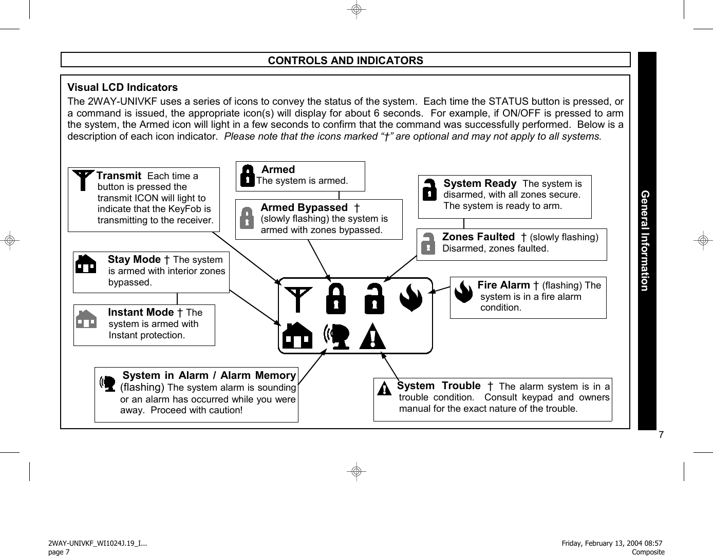
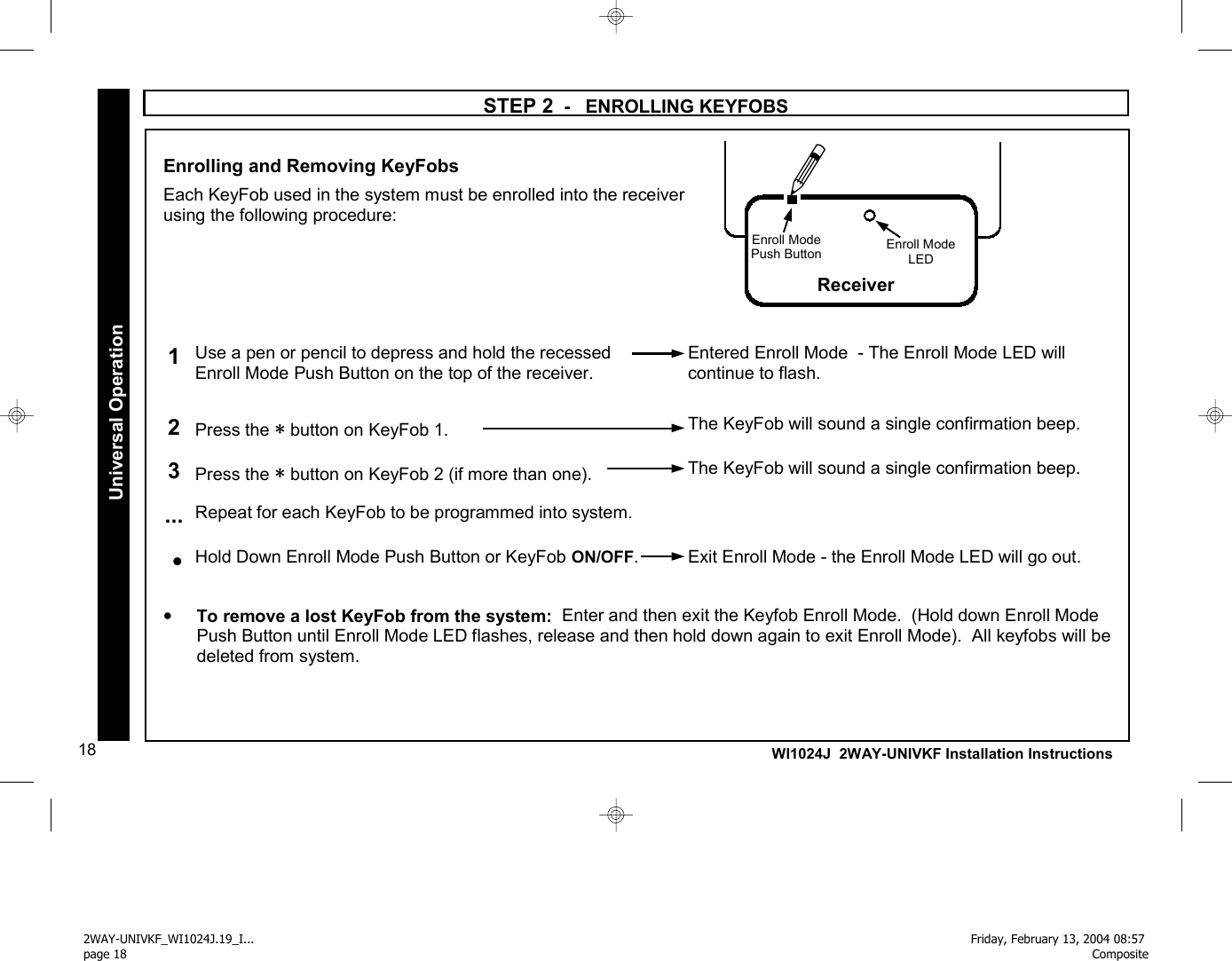
![11 STEP 2 - ENROLLING KEYFOBS--With ADEMCO Panels/Keypads Enrolling and Removing KeyFobs Each KeyFob must be enrolled into the receiver. The following procedure is used to enroll the unique RF ID number stored in the non-volatile memory of each KeyFob into the receiver memory. 1 Arm system from any keypad 2 Disarm system from any keypad 3 Press 1114, then [AWAY] on keypad The Enroll Mode LED will flash rapidly. The keypad may sound error beeps* - ignore. 4 Press the ∗ button on KeyFob 1 The KeyFob will sound a single confirmation beep. .... Repeat for each KeyFob to be enrolled Press C on Keypad Exit Enroll Mode - the Enroll Mode LED will slowly pulse. The KeyFob will give a series of beeps and the unlock icon will display. •The Keyfob Enroll Mode may also be entered / exited by pressing the the Enroll Mode Push Button on the top of the receiver. See page 18 for more information. •To Remove a lost KeyFob from the system: Enter and then exit the Keyfob Enroll Mode (Arm and disarm the system, enter 1114 [AWAY] and then press [#] ). All keyfobs will be deleted from the system. For NAPCO "Classic" Keypads, see pages 9 and 12. For NAPCO "K Series" Keypads, see pages 10 and 13. Bus Mode Operation *Some Vista models will beep, others will not. Ignore all beeps. 2WAY-UNIVKF_WI1024J.19_I... page 11Friday, February 13, 2004 08:57 Composite](https://usermanual.wiki/Napco-Security-Systems/2WAYUNIVKF/User-Guide-398864-Page-11.png)
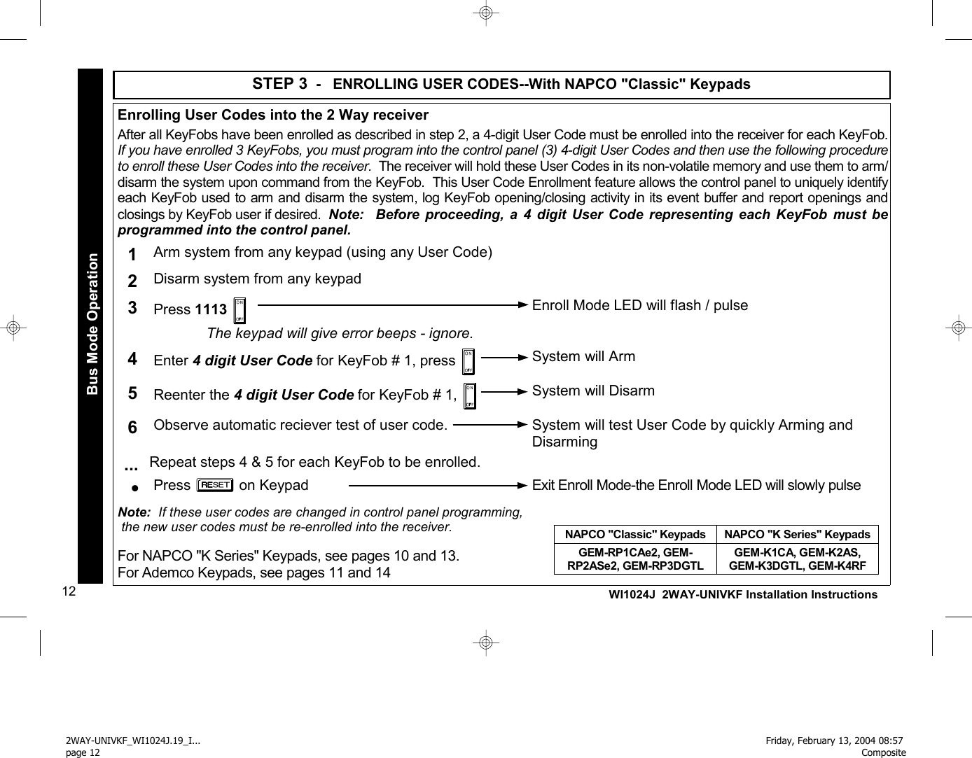
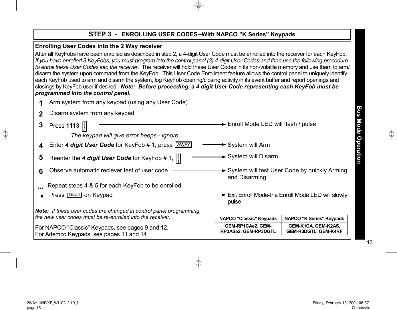
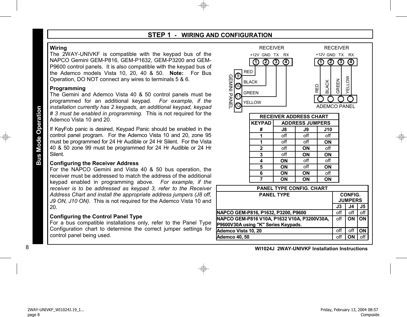
![14 WI1024J 2WAY-UNIVKF Installation Instructions STEP 3 - ENROLLING USER CODES--With ADEMCO Panels/Keypads Enrolling User Codes into the 2 Way receiver After all KeyFobs have been enrolled as described in step 2, a 4-digit User Code must be enrolled into the receiver for each KeyFob. If you have enrolled 3 KeyFobs, you must program into the control panel (3) 4-digit User Codes and then use the following procedure to enroll these User Codes into the receiver. The receiver will hold these User Codes in its non-volatile memory and use them to arm/disarm the system upon command from the KeyFob. This User Code Enrollment feature allows the control panel to uniquely identify each KeyFob used to arm and disarm the system, log KeyFob opening/closing activity in its event buffer and report openings and closings by KeyFob user if desired. Note: Before proceeding, a 4 digit User Code representing each KeyFob must be programmed into the control panel. 1 Arm system from any keypad (using any User Code) 2 Disarm system from any keypad 3 Press 1113 [AWAY] The keypad may sound error beeps* - ignore. Enroll Mode LED will flash / pulse 4 Enter 4 digit User Code for KeyFob # 1, press [AWAY] System will Arm 5 Reenter the 4 digit User Code for KeyFob # 1, [OFF] System will Disarm 6 Observe automatic reciever test of user code. System will test User Code by quickly Arming and Disarming ... Repeat steps 4 & 5 for each KeyFob to be enrolled. • Press [#] on Keypad Exit Enroll Mode-the Enroll Mode LED will slowly pulse Note: If these user codes are changed in control panel programming, the new user codes must be re-enrolled into the receiver. For NAPCO "Classic" Keypads, see pages 9 and 12. For NAPCO "K Series" Keypads, see pages 10 and 13. Bus Mode Operation *Some Vista models will beep, others will not. Ignore all beeps. 2WAY-UNIVKF_WI1024J.19_I... page 14Friday, February 13, 2004 08:57 Composite](https://usermanual.wiki/Napco-Security-Systems/2WAYUNIVKF/User-Guide-398864-Page-14.png)
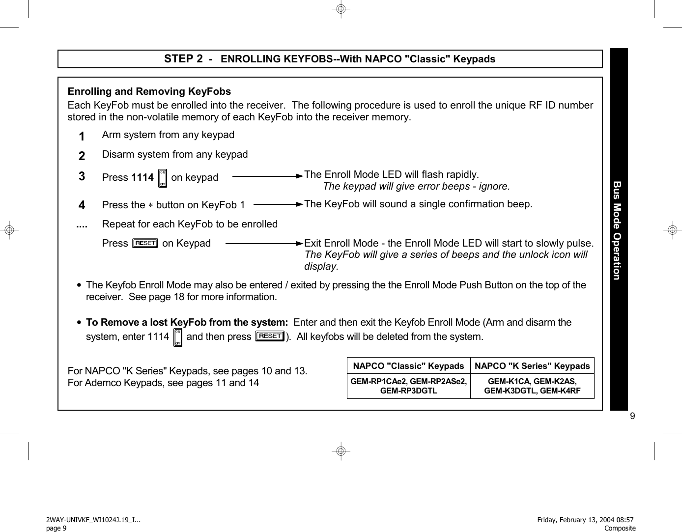
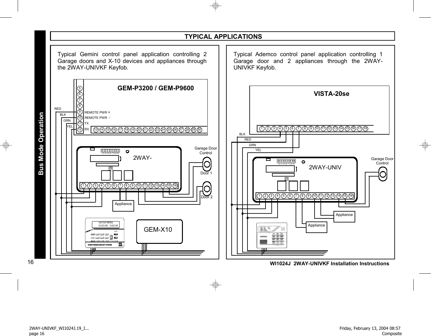
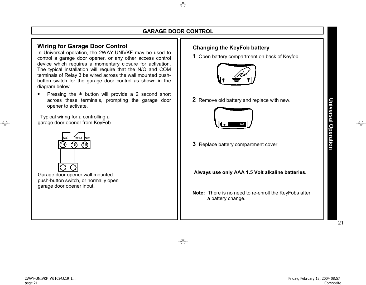
![15 GARAGE DOOR CONTROL / SPECIAL APPLICATIONS Gemini Relay Control Group Support When used on a Gemini series control which supports Relay Control Groups (GEM-P3200 & P9600), each time the KeyFob is used to activate Relay 1 or Relay 2, Relay Control groups 1 & 2 are also simultaneously activated, allowing control of external (RB3008) relays and/or X-10 devices connected to the control panel. Press [∗] to momentarily activate Relay 3 to open a garage door. COM N/O N/C 14 15 16 Garage door opener wall mounted push-button, or normally open garage door opener input. Relay 3 Garage Door Control Lighting or other special application device. Press [ON/OFF] and [∗] simultaneously to toggle Relay 1 On / Off COM 8 N/O N/C 9 10 + - Relay 1 Appliance Control + Low Voltage Hold Down [∗] for 2 seconds to toggle Relay 2 On / Off COM 11 N/O N/C 12 13 Lighting or other special application device. + - Relay 2 Appliance Control + Low Voltage Hold Down [∗] for 2 sec. to momentarily activate Relay 2 to open a second garage door. COM N/O N/C 11 12 13 Garage door opener wall mounted push-button, or normally open garage door opener input. Relay 2 Second Garage Door Control Install Jumper across Config Pins J6 J6 Bus Mode Operation When installed on the bus of a Gemini or Ademco control panel, receiver Relays 1 and 2 are available for other applications such as lighting or appliance control, while Relay 3 remains dedicated to the control of a garage door opener. •Press [ON/OFF] and [∗] simultaneously to toggle Relay 1 On / Off •Hold Down [∗] for 2 seconds to toggle Relay 2 On / Off OR •Hold Down [∗] for 2 sec. to momentarily activate Relay 2 to open a second garage door. (Install Jumper 6 - Relay 2 momentary). 2WAY-UNIVKF_WI1024J.19_I... page 15Friday, February 13, 2004 08:57 Composite](https://usermanual.wiki/Napco-Security-Systems/2WAYUNIVKF/User-Guide-398864-Page-15.png)
![17 Wiring for Arm / Disarm Program a zone on the control panel for “Keyswitch Arm” •When [ON/OFF] is pressed, the Arm/Disarm relay will change state (from normally closed to normally open) for 2 seconds and then restore, causing the control panel to arm or disarm. Zone programmed for Keyswitch Arm Typical Keyswitch wiring for a zone using End of Line resistors EOLR COM 8 N/O N/C 9 10 Typical Keyswitch wiring for a “zone doubled” zone Zone programmed for Keyswitch Arm COM 8 N/O N/C 9 10 ZDR* Wiring for Panic Program a zone on the control panel as a 24 Hour Panic Zone. •When [PANIC] is pressed, the Panic relay will change state (from normally closed to normally open) for 2 seconds and then restore, causing an alarm on the the control panel Panic Zone. Zone programmed for 24 hour panic Typical Panic wiring for a zone using End of Line resistors Zone programmed for 24 hour panic Typical Panic wiring for a “zone doubled” zone EOLR COM 11 N/O N/C 12 13 COM 11 N/O N/C 12 13 ZDR STEP 1 - WIRING FOR ARM / DISARM AND PANIC Universal operation requires the use of control panel zones to provide Arm / Disarm and Panic operation. One zone must be programmed as a keyswitch arm zone which will process a 2 second violation as an Arm / Disarm command. The other zone must be programmed as a 24 hour panic zone, which will process a 2 second violation as a panic alarm. The wiring instructions below include wiring schemes for control panels which support zone doubling, such as the NAPCO Express series. EOLR PANEL ZONE DOUBLED PANEL EOLR PANEL ZONE DOUBLED PANEL * ZDR = Zone Doubling Resistor * ZDR = Zone Doubling Resistor Universal Operation 2WAY-UNIVKF_WI1024J.19_I... page 17Friday, February 13, 2004 08:57 Composite](https://usermanual.wiki/Napco-Security-Systems/2WAYUNIVKF/User-Guide-398864-Page-17.png)
![20 WI1024J 2WAY-UNIVKF Installation Instructions Universal Operation Wiring for Stay Mode When installed on a control panel which provides “Automatic Interior Bypass”, the system can be armed in either the AWAY or STAY mode through the KeyFob. A system which provides “Automatic Interior Bypass” controls the Interior protection by automatically bypassing the Interior Zones if the system is armed and the exit/entry door is not opened. Program the control panel for “Automatic Interior Bypass”, or for “Home Away with Delay” (for the NAPCO Express Series Stay mode). Each time the system is armed by a press of KeyFob button [ON/OFF], the system will arm in the AWAY mode, providing complete protection. If the KeyFob button [ON/OFF] is held down for 2 seconds, the system will arm in the in the STAY mode, providing perimeter protection only. Choose the appropriate wiring scheme for your control panel. •When KeyFob button [ON/OFF] is pressed, the PGM terminal of the receiver will cause a violation of the exit entry zone, which will arm the system in the AWAY mode. •If KeyFob button [ON/OFF] is held down for 2 seconds, the system will arm without the PGM violation of the E/E zone, which will arm the system in the STAY mode. For the NAPCO Express Series and GEM-P400/P800 controls: •Program the interior zones for for home away with delay and wire as shown. •Install jumper J2 to invert PGM operation Zone programmed for Exit Entry Typical STAY mode wiring for a control panel using End of Line resistors Protective zone device and EOLR PGM 5 6 7 + - EOLR Typical STAY mode wiring for a control panel using Zone Doubling Zone programmed for Exit Entry Protective zone device and Zone Doubling Resistor. PGM 5 6 7 + - ZDR Wiring for Stay Mode Install Jumper across Config Pins J2 J2 EOLR PANEL ZONE DOUBLED PANEL 2WAY-UNIVKF_WI1024J.19_I... page 20Friday, February 13, 2004 08:57 Composite](https://usermanual.wiki/Napco-Security-Systems/2WAYUNIVKF/User-Guide-398864-Page-20.png)
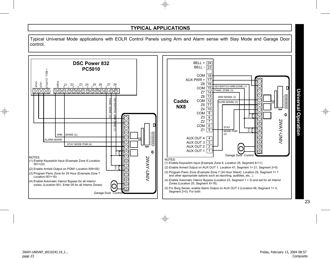
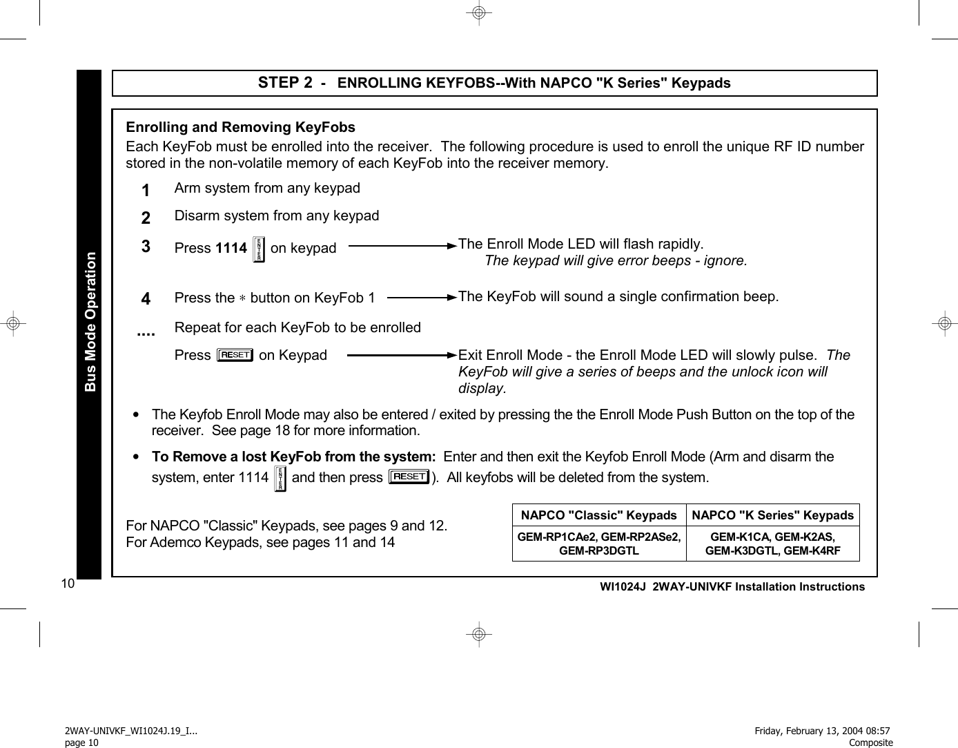
![22 WI1024J 2WAY-UNIVKF Installation Instructions GARAGE DOOR CONTROL TYPICAL APPLICATIONS 1 2 3 4 5 6 7 8 9 10 1 2 3 4 5 6 7 8 9 10 11 12 13 14 15 16 2WAY-UNIV VVVV VVV EOL VVV EOL EOL ARM SENSE ALARM SENSE + PWR - PWR STAY MODE PGM (3) KEYSWITCH ZONE 7 (1) PANIC ZONE ZONE 6 (2) E/E ZONE$ NOTES: (1) Enable Keyswitch Input on Zone 7 [183-8]. (2) Program Panic Zone 6 for 24 Hour [199-2]. (3) Enable Automatic Group Bypass [065-4] and program all Interior Zones for Group Bypass [196 -X, 197-X] (4) For BOTH Fire AND Burg sense, (2) IN4001 diodes are required as shown. For EITHER Fire OR Burg sense, no diodes are required. 6 7 8 9 5 12 REM.PWR + MA1008e 13 14 15 16 17 18 19 20 21 22 23 24 25 26 REM. PWR - 4 E4 ARMED LUG 10 11 + Z1 - + + + - Z2 Z4 Z3 + + + Z5 Z7 Z6 - E9 Fire LUG E10 Burg LUG (4) Garage Door Control Typical Universal Mode applications with EOLR Control Panel (MA1008e) and Zone Doubled Control Panel (GEM-P800) using Arm and Alarm sense with Stay Mode and Garage Door control. Universal Operation 1 2 3 4 5 6 7 8 9 10 1 2 3 4 5 6 7 8 9 10 11 12 13 14 15 16 2WAY-UNIV Garage Door Control KEYSWITCH ARM NOTES: (1) Enable Keyswitch Input on Zone 6 [26-1]. (2) Enable Armed Output on PGM [25-4]. (3) Program Zone 5 for 24 Hour [05-5]. (4) Enable Home/Away with Delay [01-X] for all Interior zones VVV 2.2K ZONE 6 (1) PANIC ZONE ZONE 5 (3) VVV E/E ZONE 1 $ STAY MODE PGM (4) ARM SENSE (2) 2.2K ALARM SENSE GEM-P800 1 2 3 4 5 6 7 8 9 10 11 12 13 14 Z1/2 + - + + Z3/4 Z5/6 - 15 PGMM - PWRR + PWRR + BELL OUTPUTT 16 17 18 19 VVV 3.9K 2WAY-UNIVKF_WI1024J.19_I... page 22Friday, February 13, 2004 08:57 Composite](https://usermanual.wiki/Napco-Security-Systems/2WAYUNIVKF/User-Guide-398864-Page-22.png)