Napco Security Systems 2WAYUNIVKF 2-Way Universal LCD Keyfob User Manual 2WAY UNIVKF WI1024J 19 INST PDF pub
Napco Security Systems Inc 2-Way Universal LCD Keyfob 2WAY UNIVKF WI1024J 19 INST PDF pub
Users Manual
WI1024J 1/04
© NAPCO 2004
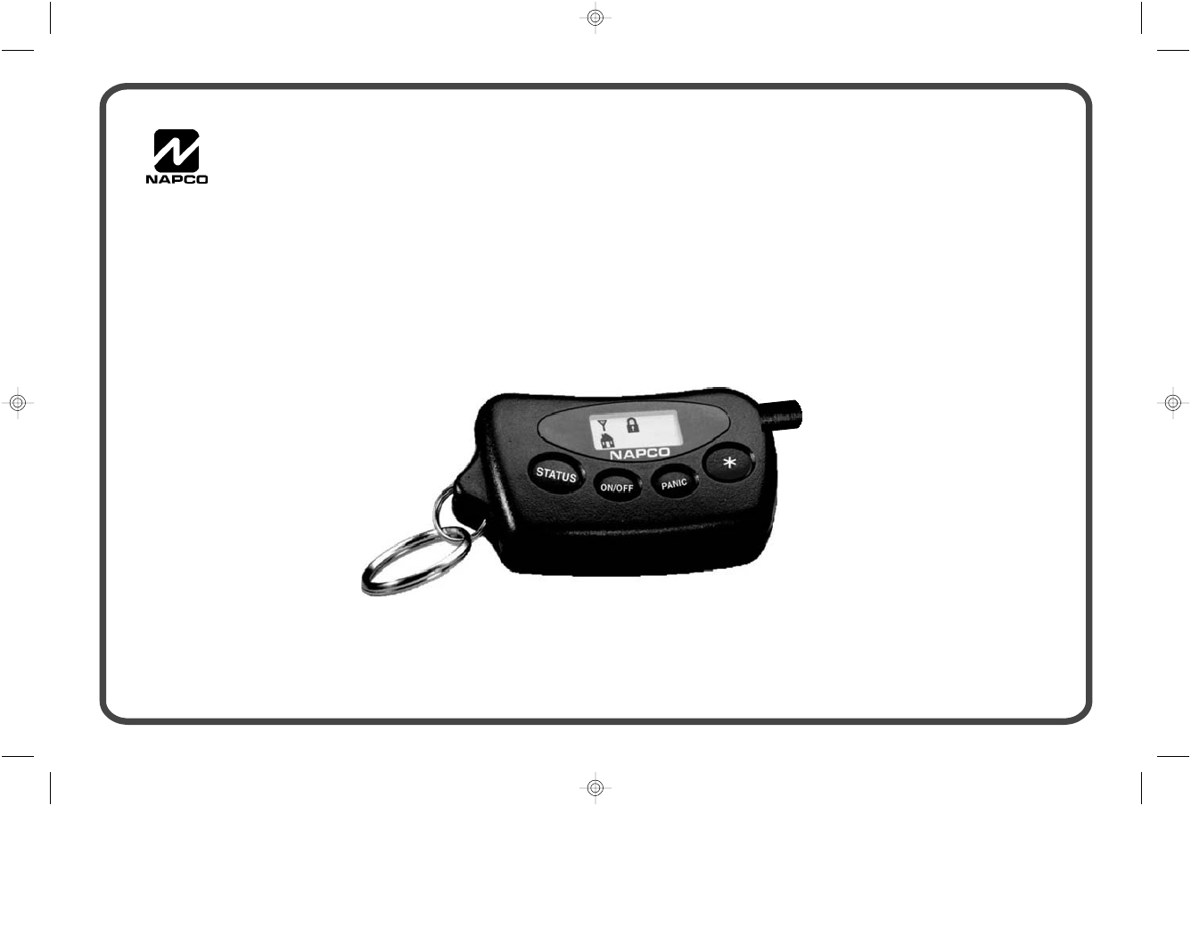
® 2WAY-UNIVKF
Bi-Directional LCD KeyFob
Installation Instructions
2WAY-UNIVKF_WI1024J.19_I...
page 1
Friday, February 13, 2004 08:57
Composite
2WI1024J 2WAY-UNIVKF Installation Instructions
NAPCO introduces the new 2WAY-UNIVKF, the security industry’s only universal bi-
directional Keyfob with LCD status display and integral mini sounder, supported by a
revolutionary 2-way receiver.
Designed to be compatible with most major control panel brands, including NAPCO's
Gemini and Magnum and others such as ADEMCO, DSC and more, this 2-Way Keyfob is
super-miniaturized for portability yet packs tremendous sales potential and consumer market
appeal.
System Status is indicated through 7 intuitive ICONS (a lock, a house, a flame, etc.) on the
LCD display, accompanied by corresponding beep sequences on its mini sounder. Providing
both easily understood visual and audible feedback, the user always knows with certainty that
the system has carried out their command.
In addition to the many standard commands it can issue the system, it can also control up to 2
groups of lighting control, such as X-10, and up to 2 separate Garage Doors.
NAPCO 2WAY-UNIVKF keyfobs are also sold in a kit with the 2-way receiver, Model
2WAY–UNIVKFKIT. Each receiver supports up to 7 keyfobs.
2WAY-UNIVKF - The 2-Way Universal LCD Keyfob that puts the power of a keypad in your pocket.
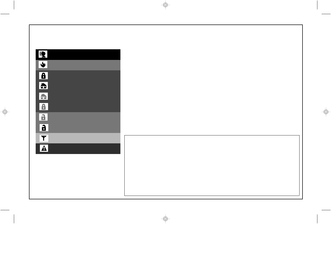
Easy LCD ICON Indicators
Burglar Alarm
Fire Alarm
Armed - Away
Armed - Stay
Armed - Instant
Armed - Zones Bypassed
Disarmed - Zones Faulted
Disarmed - System Ready
Transmit
System Trouble
Note: Grey ICON indicates pulsing
THE FOLLOWING STATEMENT IS REQUIRED BY THE FCC.
INSTRUCTION TO THE USER (if device contains a digital device)
This equipment has been tested and found to comply with the limits for a class B digital device, pursuant to part 15 of the FCC Rules.
These limits are designed to provide reasonable protection against harmful interference in a residential installation. This equipment
generates, uses and can radiate radio frequency energy and if not installed and used in accordance with the instructions, may cause
harmful interference to radio communications. However, there is no guarantee that interference will not occur in a particular installa-
tion. If this equipment does cause harmful interference to radio or television reception, which can be determined by turning the
equipment off and on, the user is encouraged to try to correct the interference by one or more of the following measures:
* Reorient or relocate the receiving antenna.
* Increase the separation between the equipment and receiver.
* Connect the equipment into an outlet on a circuit different from that to which the receiver is connected.
* Consult the dealer or an experienced radio/TV technician for help.
This equipment has been certified to comply with the limits for a class B computing device, pursuant to FCC Rules. In order to main-
tain compliance with FCC regulations, shielded cables must be used with this equipment. Operation with non-approved equipment
or unshielded cables is likely to result in interference to radio and TV reception. The user is cautioned that changes and modifica-
tions made to the equipment without the approval of manufacturer could void the user's authority to operate this equipment.
2WAY-UNIVKF_WI1024J.19_I...
page 2
Friday, February 13, 2004 08:57
Composite
3
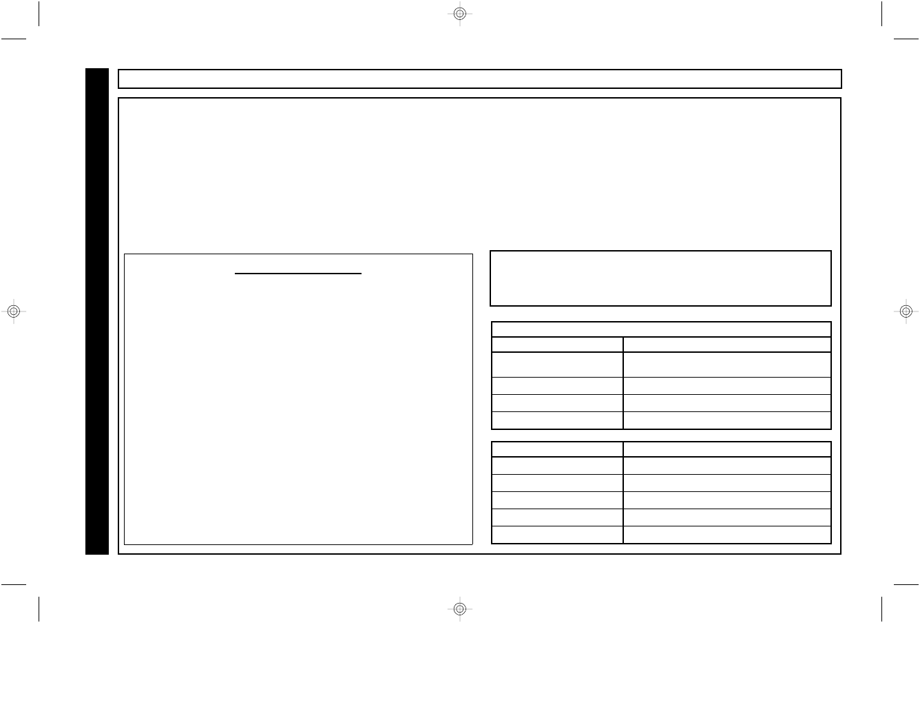
General Description
The 2WAY-UNIVKF is a miniature
remote control device which provides
wireless control of the security system
and confirms system status visually and
audibly with an LCD ICON display and
mini sounder. It is keypad bus
compatible with the NAPCO Gemini
Series control panels as well as the
Ademco Vista 10, 20, 40 & 50 series. It
is also universally compatible with any
control panel which offers keyswitch
arming with an armed status output.
Keypad Bus compatible control panels:
NAPCO: GEM-P816
GEM-P1632
GEM-P3200
GEM-P9600
Ademco: Vista 10
Vista 20
Vista 40
Vista 50
Vista 40
For additonal information and details on
universal operation, see system
overview on page 4.
Features
•3 Form C Relay Outputs
•Arm/Disarm
•Panic
•Garage Door Control
•Lighting Control or Second Garage Door
control
Specifications
•Input Voltage: 12V DC Nominal
•Input Current: 40mA standby, 90mA max.
(all relays active)
•Operating Temperature: 0-49°C (32-120°F)
•Maximum # of KeyFobs supported: 7
•Dimensions:
•Receiver: 6 3/4“ X 3 5/8” X 1 1/2”
•KeyFob: 2 “ X 1 3/8” X 1/2”
•Relay Contact Rating: 1A @ 24 VDC
•KeyFob Battery: 1.5V Alkaline AAA size
•Frequency: 433.92 Mhz
•Operating Range: 750 feet (open air)
TABLE OF CONTENTS
Section Page
GENERAL DESCRIPTION ..............................................3
SYSTEM OVERVIEW .....................................................4
WIRING DIAGRAM/ CONFIGURATION .........................5
CONTROLS AND AUDIBLE INDICATORS .....................6
VISUAL INDICATORS ....................................................7
BUS MODE WIRING AND CONFIG ...............................8
BUS MODE ENROLLING KEYFOBS .........................9-11
BUS MODE ENROLLING USER CODES ................12-14
BUS MODE GARAGE DOOR & SPECIAL APPS ........15
BUS MODE - TYPICAL APPLICATIONS .....................16
UNIVERSAL MODE WIRING ARM/DISARM/PANIC ....17
UNIVERSAL MODE ENROLLING KEYFOBS ...............18
UNIVERSAL MODE ARM / ALARM SENSE .................19
UNIVERSAL MODE WIRING FOR STAY MODE ..........20
UNIVERSAL MODE GARAGE DOOR CONTROL ........21
CHANGING THE KEYFOB BATTERY ..........................21
UNIVERSAL MODE - TYPICAL APPLICATIONS .........22
WARRANTY ..................................................................24
For Technical Assistance, Contact the NAPCO
Toll Free Helpline ! (800) 645-9440
NAPCO Security Systems, Inc.
333 Bayview Avenue, Amityville, New York 11701
For Sales and Repairs, call Toll Free: (800) 645-9445
2WAY-UNIVKF_WI1024J.19_I...
page 3
Friday, February 13, 2004 08:57
Composite
4WI1024J 2WAY-UNIVKF Installation Instructions
SYSTEM OVERVIEW
The 2WAY-UNIVKF is compatible with virtually any control
panel, either through keypad bus operation or universal
mode operation. When used on a panel on which it is bus-
compatible, full functionality is realized, including lighting,
appliance and X10 control. When used in the Universal
Mode, functionality is dependent on the feature set of the
control panel, such as a keyswitch arm zone for arm /
disarm capability, an armed output to provide an Armed
indication, a steady bell output for an alarm indication, etc.
This manual is divided into 3 sections which are marked on the
outer border of each page - General Information (pages 2-7),
Bus Mode Operation (pages 8-16) and Universal Operation
(pages 17-23). After reviewing the General Information section
for an overview of the system, refer to the section which
applies to the type of installation at hand, Bus or Universal.
Each section includes 3 mandatory steps (marked at the
top of the page) which must be completed to achieve an
operational system. All other steps are optional.
General Information
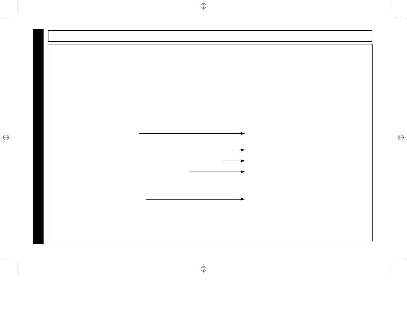
Universal Mode Features
Keyfob Commands Required Control Panel Feature
•Arm / Disarm Keyswitch arm zone or input
(Momentary)
•Stay Mode Arming Automatic Interior Bypass
•Panic 24 hour panic zone
•Garage Door Control Standard
Keyfob Indicators Required Control Panel Feature
•Armed / Disarmed Armed output or lug (high or low)
•Armed Stay Automatic Interior Bypass
•Alarm Steady bell output (high or low)
•Alarm Memory Steady bell output (high or low)
•Fire Alarm Pulsing Bell output (high or low)
!
Use these tables to determine the Keyfob functionality
you can expect from the control panel’s features.
"
Bus Mode Features
Keyfob Commands
Arm / Disarm
Stay Mode Arming
Arming with Instant Protection
Panic
Garage Door Control
Appliance Control 1 / † Relay Group 1 Control
Garage 2 or Appliance Control 2/ † Relay Group 2 Control
Keyfob Indicators
Armed
Armed Stay
Armed Instant
Armed / Zones Bypassed
Disarmed / System Ready
Disarmed / Zones Faulted
Alarm
Alarm Memory
Fire Alarm
System Trouble
† NAPCO GEM-P3200 & P9600 only
2WAY-UNIVKF_WI1024J.19_I...
page 4
Friday, February 13, 2004 08:57
Composite
5
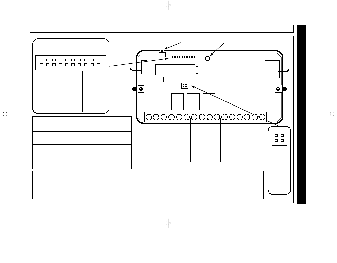
WIRING DIAGRAM AND SYSTEM CONFIGURATION
Invert Alarm Sense A
Invert Armed Sense B
General Information
KeyFob Enroll Mode Rapid Flash
User Code Enroll Mode Rapid Flash / Pulse
Universal Mode Steady
Bus Mode Pulsing
If not pulsing in Bus Mode,
check the following:
--Keypad not programmed
--Bus wiring incorrect
Receiver LED Indications
Mounting the Receiver
The 2 way receiver should be mounted in a location which is centrally located within the area of anticipated usage. It is
not recommended that the receiver be installed in an attic or mounted within 24 inches of any metallic objects.
Installation in a basement will result in reduced range. It should not be mounted in the control panel enclosure. The
receiver must be positioned with the antennas pointed up.
RES
RE4
RE3
RE2
RE1
R2T
AR
A3
A2
A1
Reserved J1
Invert Stay PGM J2
J3
J4
J5
Relay 2 momentary J6
Reserved J7
J8
J9
J10
System Configuration Jumpers
Keypad
Address
Jumpers
See
page 8
Panel
Type
Jumpers
See
page 8
A B
Enroll Mode Push Button Receiver LED
•
•
1 2 3 4 5 6 7 8 9 10
4
1 2 3 8
5 6 7 12
9 10 11 16
13 14 15
RED +12V DC
BLACK Ground
GREEN RX
YELLOW TX
Armed Sense Input
Alarm Sense Input
PGM
N/O
COM
N/C
N/O
COM
N/C
N/O
COM
N/C
Relay 1
Keyswitch
Arm
Relay 2
Panic Relay 3
Garage
Door
2WAY-UNIVKF_WI1024J.19_I...
page 5
Friday, February 13, 2004 08:57
Composite
6WI1024J 2WAY-UNIVKF Installation Instructions
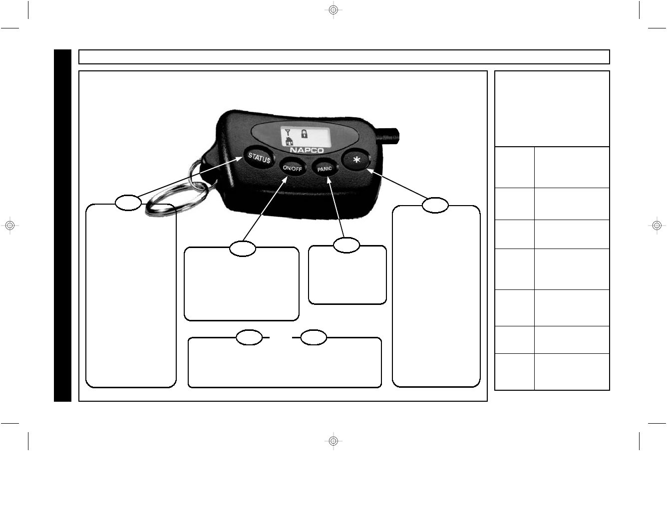
# of
Beeps
Status
1 Armed
2 Disarmed
3 Armed,
Stay mode
4 Armed, zones
bypassed
5 † System Trouble
6...
(repeats)
Alarm !
Audible Indicators
Each time a command is
issued, the KeyFob’s mini
sounder will issue an
audible confirmation beep
with the visual indication.
CONTROLS AND INDICATORS
General Information
ON/OFF ∗
AND
Press ON/OFF and ∗ simultaneously to
activate lighting or other special application.†
† Bus Operation Only
Press STATUS to
update the display
with the current
system status.
The proper icon(s)
will appear, accom-
panied by the appr-
opriate beep(s). (see
Audible Indicators)
The icon(s) will
automatically go out
in about 6 seconds.
STATUS
Press ON/OFF to arm or
disarm the alarm system.
Hold Down ON/OFF to Arm
the system in STAY mode.
Press and hold again to acti-
vate Instant arming.
ON/OFF
Hold Down PANIC
for 2 seconds to
activate a panic
alarm.
PANIC
∗
Press ∗ to open
garage door
Hold Down ∗ for 2
seconds to activ-
ate lighting or
other special appl-
ication. †
OR
Hold Down ∗ for 2
seconds to open a
second garage
door. †
Controls
The KeyFob’s 4 command buttons provide complete system control. Commands are issued to
the alarm system by either pressing or holding down (for 2 seconds) the appropriate button.
2WAY-UNIVKF_WI1024J.19_I...
page 6
Friday, February 13, 2004 08:57
Composite
7
CONTROLS AND INDICATORS
General Information
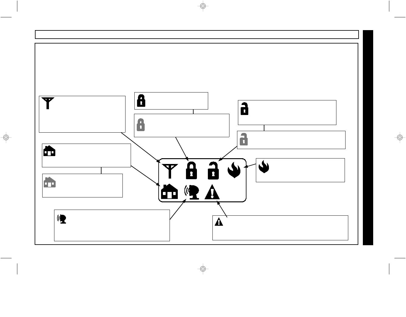
Visual LCD Indicators
The 2WAY-UNIVKF uses a series of icons to convey the status of the system. Each time the STATUS button is pressed, or
a command is issued, the appropriate icon(s) will display for about 6 seconds. For example, if ON/OFF is pressed to arm
the system, the Armed icon will light in a few seconds to confirm that the command was successfully performed. Below is a
description of each icon indicator. Please note that the icons marked “†” are optional and may not apply to all systems.
System in Alarm / Alarm Memory
(flashing) The system alarm is sounding
or an alarm has occurred while you were
away. Proceed with caution!
System Trouble † The alarm system is in a
trouble condition. Consult keypad and owners
manual for the exact nature of the trouble.
System Ready The system is
disarmed, with all zones secure.
The system is ready to arm.
Zones Faulted † (slowly flashing)
Disarmed, zones faulted.
Stay Mode † The system
is armed with interior zones
bypassed.
Instant Mode † The
system is armed with
Instant protection.
Transmit Each time a
button is pressed the
transmit ICON will light to
indicate that the KeyFob is
transmitting to the receiver.
Armed Bypassed †
(slowly flashing) the system is
armed with zones bypassed.
Armed
The system is armed.
Fire Alarm † (flashing) The
system is in a fire alarm
condition.
2WAY-UNIVKF_WI1024J.19_I...
page 7
Friday, February 13, 2004 08:57
Composite
8WI1024J 2WAY-UNIVKF Installation Instructions
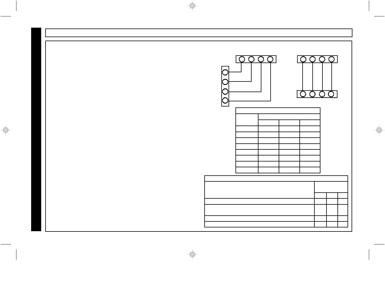
STEP 1 - WIRING AND CONFIGURATION
Wiring
The 2WAY-UNIVKF is compatible with the keypad bus of the
NAPCO Gemini GEM-P816, GEM-P1632, GEM-P3200 and GEM-
P9600 control panels. It is also compatible with the keypad bus of
the Ademco models Vista 10, 20, 40 & 50. Note: For Bus
Operation, DO NOT connect any wires to terminals 5 & 6.
Programming
The Gemini and Ademco Vista 40 & 50 control panels must be
programmed for an additional keypad. For example, if the
installation currently has 2 keypads, an additional keypad, keypad
# 3 must be enabled in programming. This is not required for the
Ademco Vista 10 and 20.
If KeyFob panic is desired, Keypad Panic should be enabled in the
control panel program. For the Ademco Vista 10 and 20, zone 95
must be programmed for 24 Hr Audible or 24 Hr Silent. For the Vista
40 & 50 zone 99 must be programmed for 24 Hr Audible or 24 Hr
Silent.
Configuring the Receiver Address
For the NAPCO Gemini and Vista 40 & 50 bus operation, the
receiver must be addressed to match the address of the additional
keypad enabled in programming above. For example, if the
receiver is to be addressed as keypad 3, refer to the Receiver
Address Chart and install the appropriate address jumpers (J8 off,
J9 ON, J10 ON). This is not required for the Ademco Vista 10 and
20.
Configuring the Control Panel Type
For a bus compatible installations only, refer to the Panel Type
Configuration chart to determine the correct jumper settings for
control panel being used.
RECEIVER
GND +12V TX
4
1 2 3
RX
12
9
10
11
RED
BLACK
GREEN
YELLOW
GEMINI PANEL
RECEIVER ADDRESS CHART
KEYPAD
# J8 J9 J10
1 off off off
1 off off ON
2 off ON off
3 off ON ON
4 ON off off
5 ON off ON
6 ON ON off
7 ON ON ON
ADDRESS JUMPERS
PANEL TYPE CONFIG. CHART
PANEL TYPE CONFIG.
JUMPERS
J3 J4 J5
NAPCO GEM-P816, P1632, P3200, P9600 off off off
NAPCO GEM-P816 V10A, P1632 V10A, P3200V30A,
P9600V30A using "K" Series Keypads.
off ON ON
Ademco Vista 10, 20 off off ON
Ademco 40, 50 off ON off
RECEIVER
GND
+12V TX
4
1 2 3
RX
RED
BLACK
GREEN
YELLOW
ADEMCO PANEL
Bus Mode Operation
2WAY-UNIVKF_WI1024J.19_I...
page 8
Friday, February 13, 2004 08:57
Composite
9
STEP 2 - ENROLLING KEYFOBS--With NAPCO "Classic" Keypads
Enrolling and Removing KeyFobs
Each KeyFob must be enrolled into the receiver. The following procedure is used to enroll the unique RF ID number
stored in the non-volatile memory of each KeyFob into the receiver memory.
1 Arm system from any keypad
2 Disarm system from any keypad
3 Press 1114 D on keypad The Enroll Mode LED will flash rapidly.
The keypad will give error beeps - ignore.
4 Press the ∗ button on KeyFob 1 The KeyFob will sound a single confirmation beep.
.... Repeat for each KeyFob to be enrolled
Press C on Keypad Exit Enroll Mode - the Enroll Mode LED will start to slowly pulse.
The KeyFob will give a series of beeps and the unlock icon will
display.
•The Keyfob Enroll Mode may also be entered / exited by pressing the the Enroll Mode Push Button on the top of the
receiver. See page 18 for more information.
•To Remove a lost KeyFob from the system: Enter and then exit the Keyfob Enroll Mode (Arm and disarm the
system, enter 1114 D and then press C). All keyfobs will be deleted from the system.
For NAPCO "K Series" Keypads, see pages 10 and 13.
For Ademco Keypads, see pages 11 and 14
Bus Mode Operation
NAPCO "Classic" Keypads NAPCO "K Series" Keypads
GEM-RP1CAe2, GEM-RP2ASe2,
GEM-RP3DGTL
GEM-K1CA, GEM-K2AS,
GEM-K3DGTL, GEM-K4RF
2WAY-UNIVKF_WI1024J.19_I...
page 9
Friday, February 13, 2004 08:57
Composite

10 WI1024J 2WAY-UNIVKF Installation Instructions
STEP 2 - ENROLLING KEYFOBS--With NAPCO "K Series" Keypads
Enrolling and Removing KeyFobs
Each KeyFob must be enrolled into the receiver. The following procedure is used to enroll the unique RF ID number
stored in the non-volatile memory of each KeyFob into the receiver memory.
1 Arm system from any keypad
2 Disarm system from any keypad
3 Press 1114 U on keypad
The Enroll Mode LED will flash rapidly.
The keypad will give error beeps - ignore.
4 Press the ∗ button on KeyFob 1 The KeyFob will sound a single confirmation beep.
.... Repeat for each KeyFob to be enrolled
Press C on Keypad Exit Enroll Mode - the Enroll Mode LED will slowly pulse. The
KeyFob will give a series of beeps and the unlock icon will
display.
•The Keyfob Enroll Mode may also be entered / exited by pressing the the Enroll Mode Push Button on the top of the
receiver. See page 18 for more information.
•To Remove a lost KeyFob from the system: Enter and then exit the Keyfob Enroll Mode (Arm and disarm the
system, enter 1114 U and then press C). All keyfobs will be deleted from the system.
For NAPCO "Classic" Keypads, see pages 9 and 12.
For Ademco Keypads, see pages 11 and 14
Bus Mode Operation
NAPCO "Classic" Keypads NAPCO "K Series" Keypads
GEM-RP1CAe2, GEM-RP2ASe2,
GEM-RP3DGTL
GEM-K1CA, GEM-K2AS,
GEM-K3DGTL, GEM-K4RF
2WAY-UNIVKF_WI1024J.19_I...
page 10
Friday, February 13, 2004 08:57
Composite
11
STEP 2 - ENROLLING KEYFOBS--With ADEMCO Panels/Keypads
Enrolling and Removing KeyFobs
Each KeyFob must be enrolled into the receiver. The following procedure is used to enroll the unique RF ID number
stored in the non-volatile memory of each KeyFob into the receiver memory.
1 Arm system from any keypad
2 Disarm system from any keypad
3 Press 1114, then [AWAY] on keypad
The Enroll Mode LED will flash rapidly.
The keypad may sound error beeps* - ignore.
4 Press the ∗ button on KeyFob 1 The KeyFob will sound a single confirmation beep.
.... Repeat for each KeyFob to be enrolled
Press C on Keypad Exit Enroll Mode - the Enroll Mode LED will slowly pulse. The
KeyFob will give a series of beeps and the unlock icon will
display.
•The Keyfob Enroll Mode may also be entered / exited by pressing the the Enroll Mode Push Button on the top of the
receiver. See page 18 for more information.
•To Remove a lost KeyFob from the system: Enter and then exit the Keyfob Enroll Mode (Arm and disarm the
system, enter 1114 [AWAY] and then press [#] ). All keyfobs will be deleted from the system.
For NAPCO "Classic" Keypads, see pages 9 and 12.
For NAPCO "K Series" Keypads, see pages 10 and 13.
Bus Mode Operation
*Some Vista models will beep, others will not. Ignore all beeps.
2WAY-UNIVKF_WI1024J.19_I...
page 11
Friday, February 13, 2004 08:57
Composite
12 WI1024J 2WAY-UNIVKF Installation Instructions
STEP 3 - ENROLLING USER CODES--With NAPCO "Classic" Keypads
Enrolling User Codes into the 2 Way receiver
After all KeyFobs have been enrolled as described in step 2, a 4-digit User Code must be enrolled into the receiver for each KeyFob.
If you have enrolled 3 KeyFobs, you must program into the control panel (3) 4-digit User Codes and then use the following procedure
to enroll these User Codes into the receiver. The receiver will hold these User Codes in its non-volatile memory and use them to arm/
disarm the system upon command from the KeyFob. This User Code Enrollment feature allows the control panel to uniquely identify
each KeyFob used to arm and disarm the system, log KeyFob opening/closing activity in its event buffer and report openings and
closings by KeyFob user if desired. Note: Before proceeding, a 4 digit User Code representing each KeyFob must be
programmed into the control panel.
1 Arm system from any keypad (using any User Code)
2 Disarm system from any keypad
3 Press 1113 D
The keypad will give error beeps - ignore.
Enroll Mode LED will flash / pulse
4 Enter 4 digit User Code for KeyFob # 1, press D System will Arm
5 Reenter the 4 digit User Code for KeyFob # 1, D System will Disarm
6 Observe automatic reciever test of user code. System will test User Code by quickly Arming and
Disarming
... Repeat steps 4 & 5 for each KeyFob to be enrolled.
• Press C on Keypad Exit Enroll Mode-the Enroll Mode LED will slowly pulse
Note: If these user codes are changed in control panel programming,
the new user codes must be re-enrolled into the receiver.
For NAPCO "K Series" Keypads, see pages 10 and 13.
For Ademco Keypads, see pages 11 and 14
Bus Mode Operation
NAPCO "Classic" Keypads NAPCO "K Series" Keypads
GEM-RP1CAe2, GEM-
RP2ASe2, GEM-RP3DGTL
GEM-K1CA, GEM-K2AS,
GEM-K3DGTL, GEM-K4RF
2WAY-UNIVKF_WI1024J.19_I...
page 12
Friday, February 13, 2004 08:57
Composite
13
STEP 3 - ENROLLING USER CODES--With NAPCO "K Series" Keypads
Enrolling User Codes into the 2 Way receiver
After all KeyFobs have been enrolled as described in step 2, a 4-digit User Code must be enrolled into the receiver for each KeyFob.
If you have enrolled 3 KeyFobs, you must program into the control panel (3) 4-digit User Codes and then use the following procedure
to enroll these User Codes into the receiver. The receiver will hold these User Codes in its non-volatile memory and use them to arm/
disarm the system upon command from the KeyFob. This User Code Enrollment feature allows the control panel to uniquely identify
each KeyFob used to arm and disarm the system, log KeyFob opening/closing activity in its event buffer and report openings and
closings by KeyFob user if desired. Note: Before proceeding, a 4 digit User Code representing each KeyFob must be
programmed into the control panel.
1 Arm system from any keypad (using any User Code)
2 Disarm system from any keypad
3 Press 1113 U
The keypad will give error beeps - ignore.
Enroll Mode LED will flash / pulse
4 Enter 4 digit User Code for KeyFob # 1, press Q System will Arm
5 Reenter the 4 digit User Code for KeyFob # 1, U System will Disarm
6 Observe automatic reciever test of user code. System will test User Code by quickly Arming
and Disarming
... Repeat steps 4 & 5 for each KeyFob to be enrolled.
• Press C on Keypad Exit Enroll Mode-the Enroll Mode LED will slowly
pulse
Note: If these user codes are changed in control panel programming,
the new user codes must be re-enrolled into the receiver.
For NAPCO "Classic" Keypads, see pages 9 and 12.
For Ademco Keypads, see pages 11 and 14
Bus Mode Operation
NAPCO "Classic" Keypads NAPCO "K Series" Keypads
GEM-RP1CAe2, GEM-
RP2ASe2, GEM-RP3DGTL
GEM-K1CA, GEM-K2AS,
GEM-K3DGTL, GEM-K4RF
2WAY-UNIVKF_WI1024J.19_I...
page 13
Friday, February 13, 2004 08:57
Composite
14 WI1024J 2WAY-UNIVKF Installation Instructions
STEP 3 - ENROLLING USER CODES--With ADEMCO Panels/Keypads
Enrolling User Codes into the 2 Way receiver
After all KeyFobs have been enrolled as described in step 2, a 4-digit User Code must be enrolled into the receiver for each KeyFob.
If you have enrolled 3 KeyFobs, you must program into the control panel (3) 4-digit User Codes and then use the following procedure
to enroll these User Codes into the receiver. The receiver will hold these User Codes in its non-volatile memory and use them to arm/
disarm the system upon command from the KeyFob.
This User Code Enrollment feature allows the control panel to uniquely identify each KeyFob used to arm and disarm the system, log
KeyFob opening/closing activity in its event buffer and report openings and closings by KeyFob user if desired.
Note: Before proceeding, a 4 digit User Code representing each KeyFob must be programmed into the control panel.
1 Arm system from any keypad (using any User Code)
2 Disarm system from any keypad
3 Press 1113 [AWAY]
The keypad may sound error beeps* - ignore.
Enroll Mode LED will flash / pulse
4 Enter 4 digit User Code for KeyFob # 1, press [AWAY] System will Arm
5 Reenter the 4 digit User Code for KeyFob # 1, [OFF] System will Disarm
6 Observe automatic reciever test of user code. System will test User Code by quickly Arming
and Disarming
... Repeat steps 4 & 5 for each KeyFob to be enrolled.
• Press [#] on Keypad Exit Enroll Mode-the Enroll Mode LED will slowly
pulse
Note: If these user codes are changed in control panel programming, the new user codes must be re-enrolled into the receiver.
For NAPCO "Classic" Keypads, see pages 9 and 12.
For NAPCO "K Series" Keypads, see pages 10 and 13.
Bus Mode Operation
*Some Vista models will beep, others will not. Ignore all beeps.
2WAY-UNIVKF_WI1024J.19_I...
page 14
Friday, February 13, 2004 08:57
Composite
15
GARAGE DOOR CONTROL / SPECIAL APPLICATIONS
Gemini Relay Control Group Support
When used on a Gemini series control which supports Relay Control Groups (GEM-P3200 & P9600), each time the
KeyFob is used to activate Relay 1 or Relay 2, Relay Control groups 1 & 2 are also simultaneously activated, allowing
control of external (RB3008) relays and/or X-10 devices connected to the control panel.
Press [∗] to momentarily activate
Relay 3 to open a garage door.
COM
N/O N/C
14 15 16
Garage door opener wall mounted
push-button, or normally open
garage door opener input.
Relay 3 Garage Door
Control
Lighting or other special
application device.
Press [ON/OFF] and [∗]
simultaneously to toggle
Relay 1 On / Off
COM
8
N/O N/C
9 10
+ -
Relay 1 Appliance
Control
+ Low
Voltage
Hold Down [∗] for 2 seconds to
toggle Relay 2 On / Off
COM
11
N/O N/C
12 13
Lighting or other special
application device.
+ -
Relay 2 Appliance
Control
+ Low
Voltage
Hold Down [∗] for 2 sec. to
momentarily activate Relay 2 to
open a second garage door.
COM
N/O N/C
11 12 13
Garage door opener wall mounted
push-button, or normally open
garage door opener input.
Relay 2 Second Garage
Door Control
Install Jumper
across Config
Pins J6
J6
Bus Mode Operation
When installed on the bus of a Gemini or Ademco control panel, receiver Relays 1 and 2 are available for other applications
such as lighting or appliance control, while Relay 3 remains dedicated to the control of a garage door opener.
•Press [ON/OFF] and [∗] simultaneously to toggle Relay 1 On / Off
•Hold Down [∗] for 2 seconds to toggle Relay 2 On / Off
OR
•Hold Down [∗] for 2 sec. to momentarily activate Relay 2 to open a second garage door. (Install Jumper 6 - Relay 2 momentary).
2WAY-UNIVKF_WI1024J.19_I...
page 15
Friday, February 13, 2004 08:57
Composite
16 WI1024J 2WAY-UNIVKF Installation Instructions
TYPICAL APPLICATIONS
1 2 3 4 5 6 7 8 9 10
1 2 3 4 5 6 7 8 9 10 11 12 13 14 15 16
6
7
8
9
10
5
11
12
REMOTE PWR +
GEM-P3200 / GEM-P9600
13 14 15 16 17 18 19 20 21 22 23 24 25 26 27 28 29 30
REMOTE PWR -
RX
TX
GEM-X10
R
COMPUTERIZED SECURITY SYSTEM
GEMINI
ARMED
STATUS
SYSTEM ARMED
01/01/97 12:00AM
12
4
3
56
7890
A
B
C
DE
F
G
NEXT/YES
PRIOR/NO
AREA
2WAY-
Garage Door
Control
Door 1
Door 2
Appliance
Typical Gemini control panel application controlling 2
Garage doors and X-10 devices and appliances through
the 2WAY-UNIVKF Keyfob.
1 2 3 4 5 6 7 8 9 10
1 2 3 4 5 6 7 8 9 10 11 12 13 14 15 16
VISTA-20se
1 2 3 4 5 6 7 8 9 10 11 12 13 14 15 16 17 18
2WAY-UNIV
Typical Ademco control panel application controlling 1
Garage door and 2 appliances through the 2WAY-
UNIVKF Keyfob.
RED
BLK
GRN
YEL
RED
BLK
GRN
YEL
Appliance
Appliance
Garage Door
Control
Bus Mode Operation
SYSTEM ARMED
01/01/00 12:00 AM
2WAY-UNIVKF_WI1024J.19_I...
page 16
Friday, February 13, 2004 08:57
Composite
17
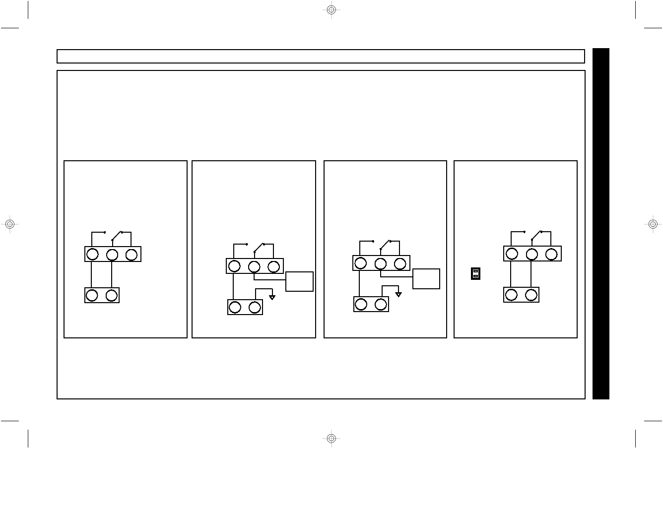
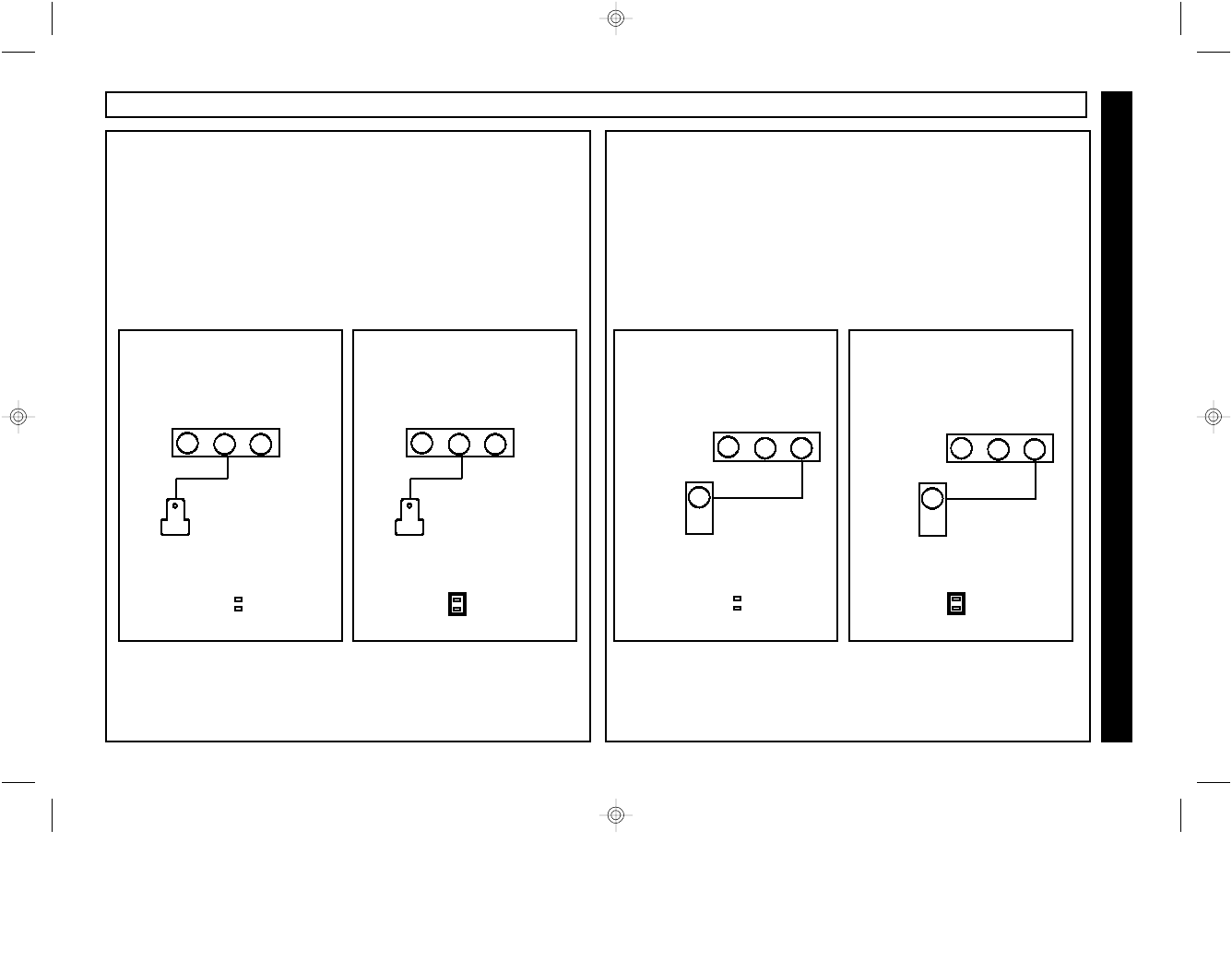
Wiring for Arm / Disarm
Program a zone on the control panel for “Keyswitch Arm”
•When [ON/OFF] is pressed, the Arm/Disarm relay will
change state (from normally closed to normally open) for 2
seconds and then restore, causing the control panel to arm
or disarm.
Zone programmed for
Keyswitch Arm
Typical Keyswitch wiring
for a zone using
End of Line resistors
EOLR
COM
8
N/O N/C
9 10
Typical Keyswitch wiring
for a “zone doubled” zone
Zone programmed for
Keyswitch Arm
COM
8
N/O N/C
9 10
ZDR*
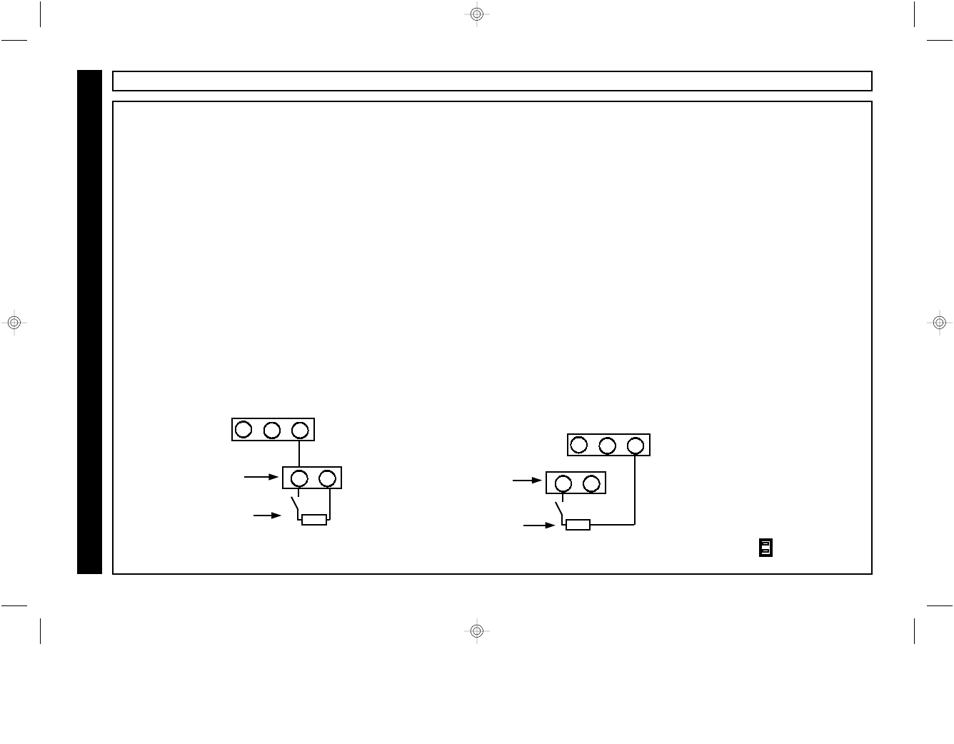
Wiring for Panic
Program a zone on the control panel as a 24 Hour Panic
Zone.
•When [PANIC] is pressed, the Panic relay will change
state (from normally closed to normally open) for 2
seconds and then restore, causing an alarm on the the
control panel Panic Zone.
Zone programmed for
24 hour panic
Typical Panic wiring
for a zone using
End of Line resistors
Zone programmed
for 24 hour panic
Typical Panic wiring
for a “zone doubled” zone
EOLR
COM
11
N/O N/C
12 13
COM
11
N/O N/C
12 13
ZDR
STEP 1 - WIRING FOR ARM / DISARM AND PANIC
Universal operation requires the use of control panel zones to provide Arm / Disarm and Panic operation. One zone must be
programmed as a keyswitch arm zone which will process a 2 second violation as an Arm / Disarm command. The other zone must
be programmed as a 24 hour panic zone, which will process a 2 second violation as a panic alarm. The wiring instructions below
include wiring schemes for control panels which support zone doubling, such as the NAPCO Express series.
EOLR PANEL ZONE DOUBLED PANEL EOLR PANEL ZONE DOUBLED PANEL
* ZDR = Zone Doubling Resistor
* ZDR = Zone Doubling Resistor
Universal Operation
2WAY-UNIVKF_WI1024J.19_I...
page 17
Friday, February 13, 2004 08:57
Composite
18 WI1024J 2WAY-UNIVKF Installation Instructions
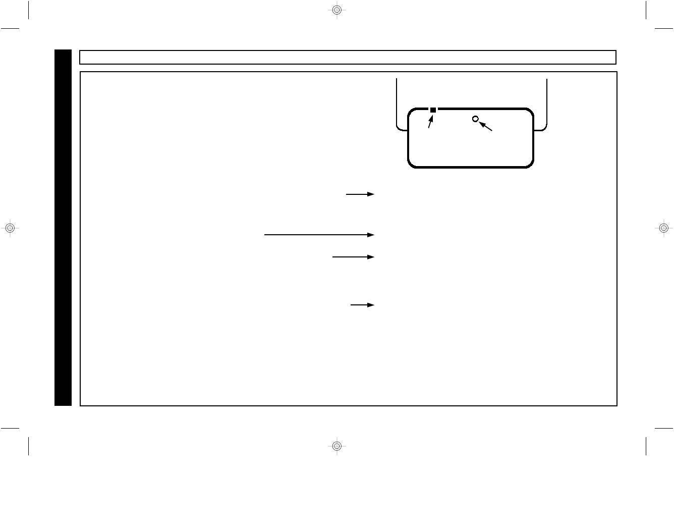
Universal Operation
Enrolling and Removing KeyFobs
Each KeyFob used in the system must be enrolled into the receiver
using the following procedure:
1 Use a pen or pencil to depress and hold the recessed
Enroll Mode Push Button on the top of the receiver.
Entered Enroll Mode - The Enroll Mode LED will
continue to flash.
2 Press the ∗ button on KeyFob 1. The KeyFob will sound a single confirmation beep.
3 Press the ∗ button on KeyFob 2 (if more than one). The KeyFob will sound a single confirmation beep.
... Repeat for each KeyFob to be programmed into system.
• Hold Down Enroll Mode Push Button or KeyFob ON/OFF. Exit Enroll Mode - the Enroll Mode LED will go out.
•To remove a lost KeyFob from the system: Enter and then exit the Keyfob Enroll Mode. (Hold down Enroll Mode
Push Button until Enroll Mode LED flashes, release and then hold down again to exit Enroll Mode). All keyfobs will be
deleted from system.
#
Enroll Mode
LED
Receiver
Enroll Mode
Push Button
STEP 2 - ENROLLING KEYFOBS
2WAY-UNIVKF_WI1024J.19_I...
page 18
Friday, February 13, 2004 08:57
Composite
19
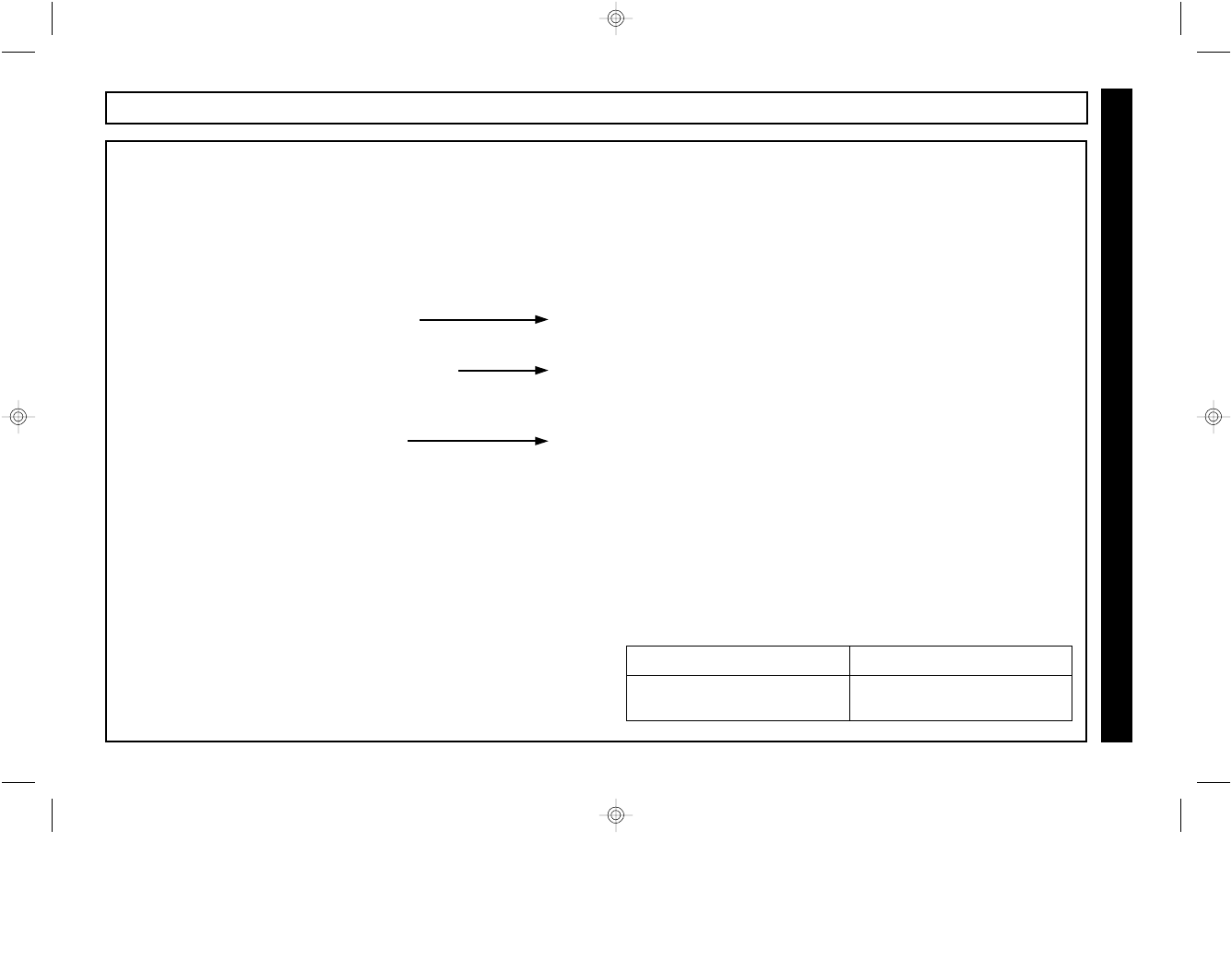
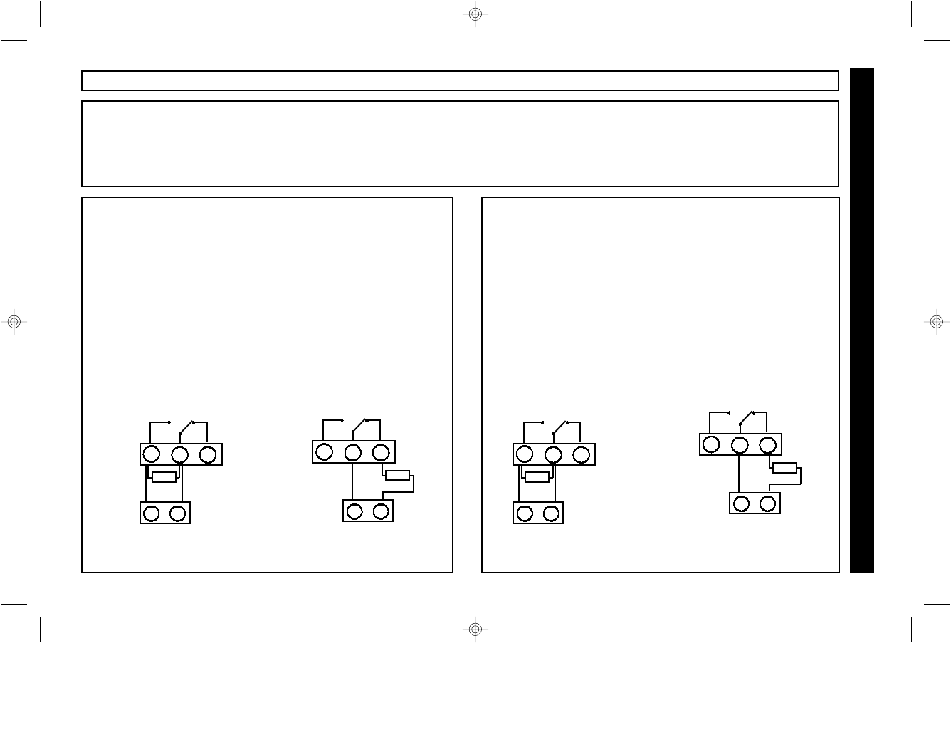
Universal Operation
Wiring for Arm Sense
In Universal Mode, the receiver requires an Armed output from
the control panel in order to pass the system status to the
KeyFob. It may be configured for either a positive sense or
negative sense.
Wiring to a control panel with
an Armed output which goes
negative upon arming.
5
Wiring to a control panel with
an Armed output which goes
positive upon arming.
5
STEP 3 - WIRING FOR ARM & ALARM SENSE
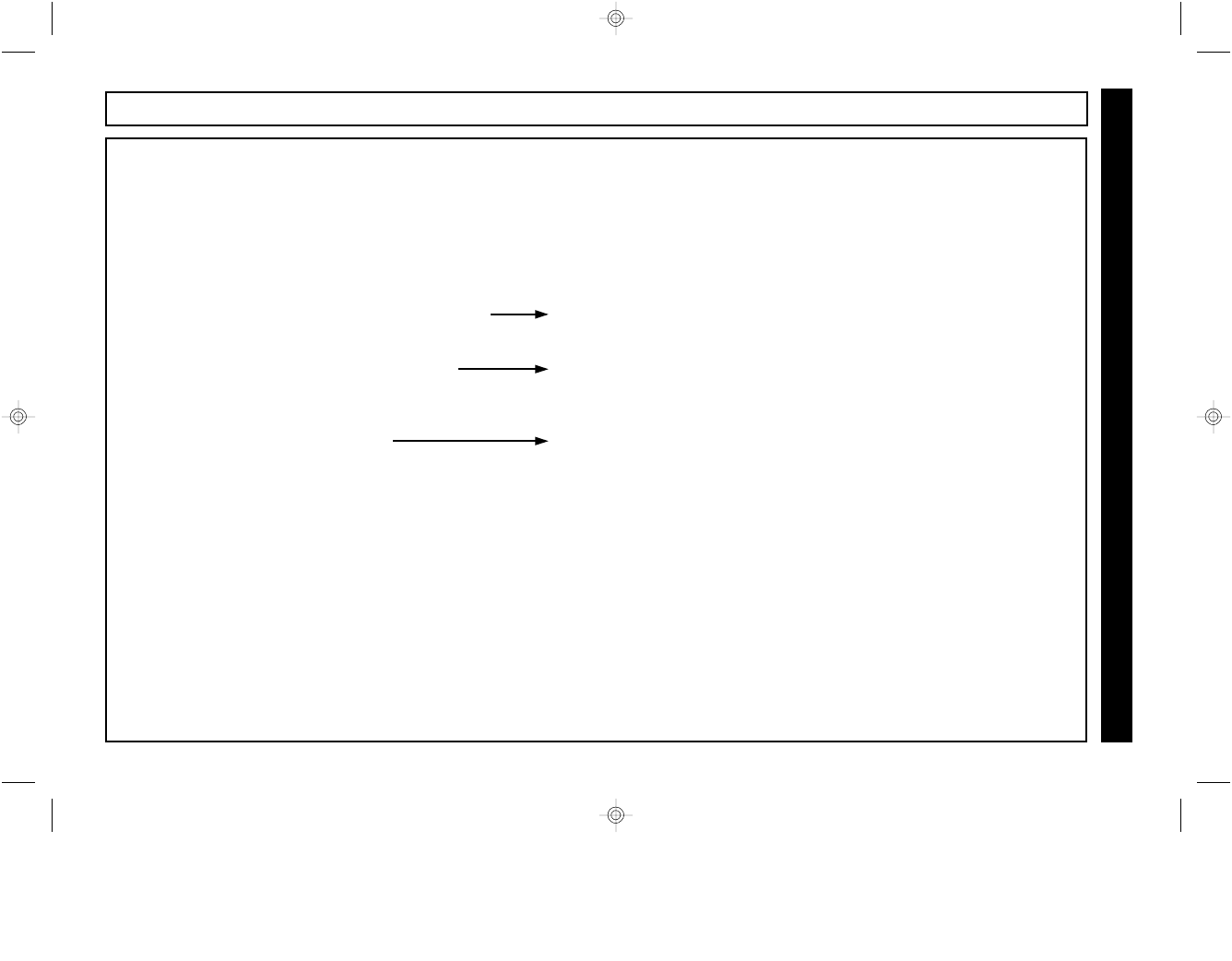
Wiring for Alarm Sense
In Universal Mode, the receiver requires an Alarm output from
the control panel in order to pass the correct status to the
KeyFob. Typical connection will be to the bell output of the
control panel. It will automatically display a siren icon for a
steady input and a fire icon for a pulsing or temporal fire output.
The Alarm Sense input may be configured for either a positive
or negative output.
Wiring to a control panel with
an Alarm output which goes
positive upon alarm.
Wiring to a control panel with
an Alarm output which goes
negative upon alarm.
6
+
Positive
Bell
Output
6
-
Negative
Alarm
Output
Negative = less than 3 V DC
Positive = greater than 7 V DC Negative = less than 3 V DC
Positive = greater than 7 V DC
Remove Jumper
from Config Pin A
A
Install Jumper on
Config Pin A
A
Remove Jumper
from Config Pin B
B
Install Jumper on
Config Pin B
B
2WAY-UNIVKF_WI1024J.19_I...
page 19
Friday, February 13, 2004 08:57
Composite
20 WI1024J 2WAY-UNIVKF Installation Instructions
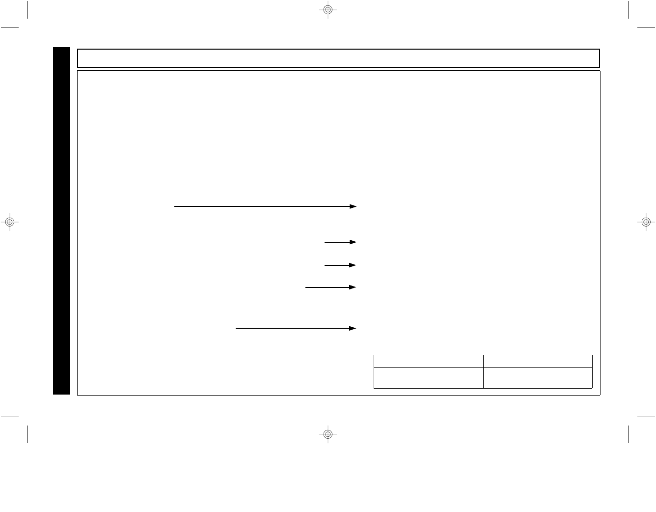
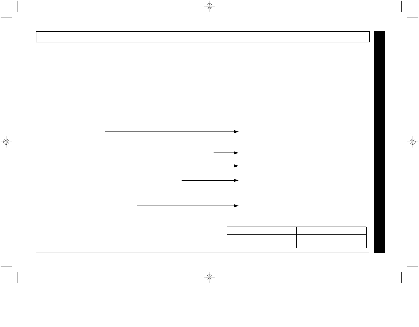
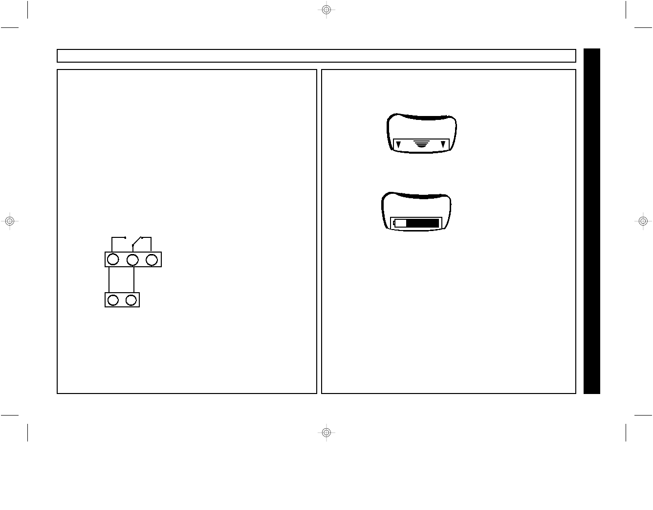
Universal Operation
Wiring for Stay Mode
When installed on a control panel which provides “Automatic Interior Bypass”, the system can be armed in either the AWAY or
STAY mode through the KeyFob. A system which provides “Automatic Interior Bypass” controls the Interior protection by
automatically bypassing the Interior Zones if the system is armed and the exit/entry door is not opened. Program the control panel
for “Automatic Interior Bypass”, or for “Home Away with Delay” (for the NAPCO Express Series Stay mode). Each time the system
is armed by a press of KeyFob button [ON/OFF], the system will arm in the AWAY mode, providing complete protection. If the
KeyFob button [ON/OFF] is held down for 2 seconds, the system will arm in the in the STAY mode, providing perimeter protection
only.
Choose the appropriate wiring scheme for your control panel.
•When KeyFob button [ON/OFF] is pressed, the PGM terminal of the receiver will cause a violation of the exit entry zone,
which will arm the system in the AWAY mode.
•If KeyFob button [ON/OFF] is held down for 2 seconds, the system will arm without the PGM violation of the E/E zone, which
will arm the system in the STAY mode.
For the NAPCO Express Series
and GEM-P400/P800 controls:
•Program the interior zones for
for home away with delay and
wire as shown.
•Install jumper J2 to invert
PGM operation
Zone programmed
for Exit Entry
Typical STAY mode wiring for a control
panel using End of Line resistors
Protective zone
device and EOLR
PGM
5 6 7
+ -
EOLR
Typical STAY mode wiring for a control
panel using Zone Doubling
Zone programmed
for Exit Entry
Protective zone device and
Zone Doubling Resistor.
PGM
5 6 7
+ -
ZDR
Wiring for Stay Mode
Install Jumper
across Config
Pins J2
J2
EOLR PANEL ZONE DOUBLED PANEL
2WAY-UNIVKF_WI1024J.19_I...
page 20
Friday, February 13, 2004 08:57
Composite
21
Universal Operation
Wiring for Garage Door Control
In Universal operation, the 2WAY-UNIVKF may be used to
control a garage door opener, or any other access control
device which requires a momentary closure for activation.
The typical installation will require that the N/O and COM
terminals of Relay 3 be wired across the wall mounted push-
button switch for the garage door control as shown in the
diagram below.
•Pressing the ∗ button will provide a 2 second short
across these terminals, prompting the garage door
opener to activate.
Garage door opener wall mounted
push-button switch, or normally open
garage door opener input.
Typical wiring for a controlling a
garage door opener from KeyFob.
COM
14
N/O N/C
15 16
GARAGE DOOR CONTROL
Note: There is no need to re-enroll the KeyFobs after
a battery change.
Always use only AAA 1.5 Volt alkaline batteries.
3 Replace battery compartment cover
Changing the KeyFob battery
!
1 Open battery compartment on back of Keyfob.
AAA
+
2 Remove old battery and replace with new.
2WAY-UNIVKF_WI1024J.19_I...
page 21
Friday, February 13, 2004 08:57
Composite
22 WI1024J 2WAY-UNIVKF Installation Instructions
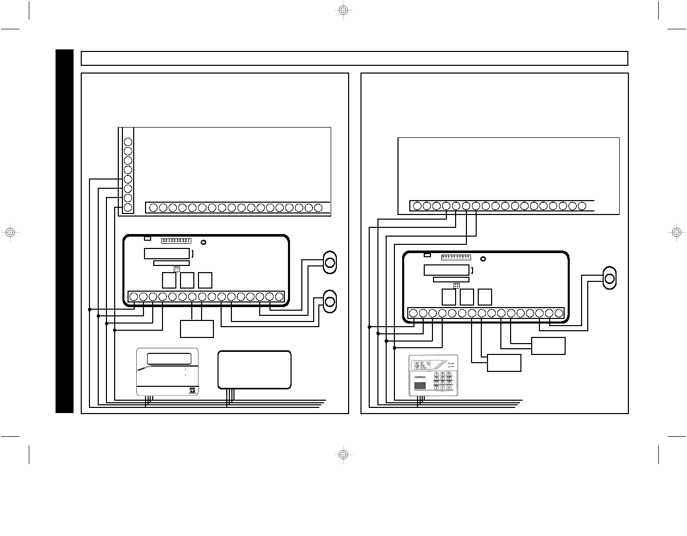
GARAGE DOOR CONTROL
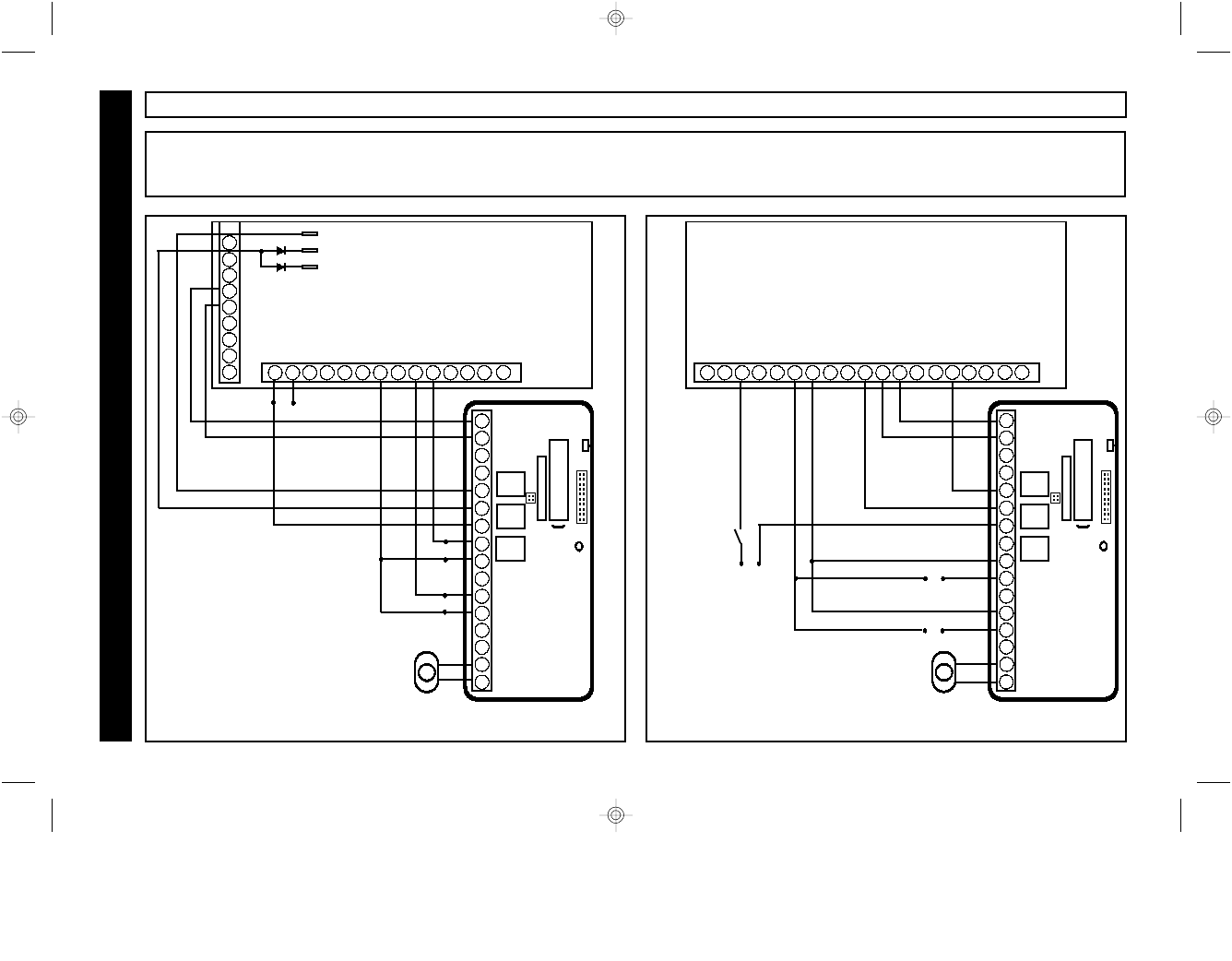
TYPICAL APPLICATIONS
1 2 3 4 5 6 7 8 9 10
1 2 3 4 5 6 7 8 9 10 11 12 13 14 15 16
2WAY-UNIV
VVVV
VVV
EOL
VVV
EOL
EOL
ARM SENSE
ALARM SENSE
+ PWR
- PWR
STAY MODE PGM (3)
KEYSWITCH ZONE 7 (1)
PANIC ZONE ZONE 6 (2)
E/E ZONE$
NOTES:
(1) Enable Keyswitch Input on Zone 7 [183-8].
(2) Program Panic Zone 6 for 24 Hour [199-2].
(3) Enable Automatic Group Bypass [065-4] and
program all Interior Zones for Group Bypass
[196 -X, 197-X]
(4) For BOTH Fire AND Burg sense, (2) IN4001
diodes are required as shown. For EITHER
Fire OR Burg sense, no diodes are required.
6
7
8
9
5
12
REM.PWR +
MA1008e
13 14 15 16 17 18 19 20 21 22 23 24 25 26
REM. PWR -
4
E4 ARMED LUG
10
11 + Z1
- + + + -
Z2 Z4
Z3
+ + +
Z5 Z7
Z6
-
E9 Fire LUG
E10 Burg LUG
(4)
Garage Door
Control
Typical Universal Mode applications with EOLR Control Panel (MA1008e) and Zone Doubled Control Panel (GEM-P800) using Arm
and Alarm sense with Stay Mode and Garage Door control.
Universal Operation
1 2 3 4 5 6 7 8 9 10
1 2 3 4 5 6 7 8 9 10 11 12 13 14 15 16
2WAY-UNIV
Garage Door
Control
KEYSWITCH ARM
NOTES:
(1) Enable Keyswitch Input on Zone 6 [26-1].
(2) Enable Armed Output on PGM [25-4].
(3) Program Zone 5 for 24 Hour [05-5].
(4) Enable Home/Away with Delay [01-X] for all
Interior zones
VVV
2.2K
ZONE 6 (1)
PANIC ZONE
ZONE 5 (3)
VVV
E/E ZONE 1 $
STAY MODE PGM (4)
ARM SENSE (2)
2.2K
ALARM SENSE
GEM-P800
1 2 3 4 5 6 7 8 9 10 11 12 13 14
Z1/2
+ - + +
Z3/4 Z5/6
-
15
PGMM
- PWRR
+ PWRR
+ BELL OUTPUTT
16 17 18 19
VVV
3.9K
2WAY-UNIVKF_WI1024J.19_I...
page 22
Friday, February 13, 2004 08:57
Composite
23
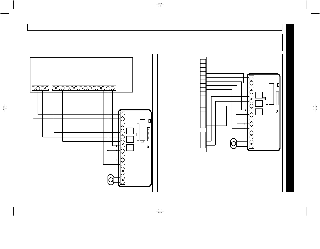
Universal Operation
GARAGE DOOR CONTROL
TYPICAL APPLICATIONS
Typical Universal Mode applications with EOLR Control Panels using Arm and Alarm sense with Stay Mode and Garage Door
control.
1 2 3 4 5 6 7 8 9 10
1 2 3 4 5 6 7 8 9 10 11 12 13 14 15 16
2WAY-UNIV
Garage Door Control
VVV
EOL
VVV
EOL
PANIC ZONE (3)
KEYSWITCH ARM ZONE (1)
STAY
BELL + 24
BELL - 23
COM 18
AUX PWR + 17
Z8 16
COM 15
Z7 14
Z6 13
COM 12
Z5 11
Z4 10
COM 9
Z3 8
Z2 7
COM 6
Z1 5
AUX OUT 4 4
AUX OUT 3 3
AUX OUT 2 2
AUX OUT 1 1
Caddx
NX8
NOTES:
(1) Enable Keyswitch Input (Example Zone 8, Location 25, Segment 8=11)
(2) Enable Armed Output on AUX OUT 1. Location 47, Segment 1= 21, Segment 2=0)
(3) Program Panic Zone (Example Zone 7 (24 Hour Silent) Location 25, Segment 7= 7
and other appropriate options such as reporting, audibles, etc...)
(4) Enable Automatic Interior Bypass (Location 23, Segment 1 = 3) and set for all Interior
Zones (Location 25, Segment X=18).
(5) For Burg Sense, enable Alarm Output on AUX OUT 2 (Location 48, Segment 1= 0,
Segment 2=0). For both
ARM SENSE (2)
ALRM SENSE (5)
MODE PGM
(4)
1 2 3 4 5 6 7 8 9 10
1 2 3 4 5 6 7 8 9 10 11 12 13 14 15 16
2WAY-UNIV
NOTES:
(1) Enable Keyswitch Input (Example Zone 8 Location
001=22)
(2) Enable Armed Output on PGM1 Location 009=05)
(3) Program Panic Zone for 24 Hour (Example Zone 7
Location 001=16)
(4) Enable Automatic Interior Bypass for all Interior
zones. (Location 001, Enter 05 for all Interior Zones)
STAY MODE PGM (4)
DSC Power 832
PC5010
3 4 5 6 11 12 13 14
Z1
+ - + +
Z2 -
15
PGM1
+AUX
- AUX
+ BELL OUTPUT
16 17 18 19 20 21 22 23 24
Z3 +
Z4 + -
Z5 +
Z6 + -
Z7 +
Z8
KEYSWITCH ARM ZONE (1)
VVV
EOL
VVV
EOL
PANIC ZONE (3)
ALARM SENSE
ARM SENSE (2)
Garage Door Control
2WAY-UNIVKF_WI1024J.19_I...
page 23
Friday, February 13, 2004 08:57
Composite
24 WI1024J 2WAY-UNIVKF Installation Instructions
NAPCO SECURITY SYSTEMS, INC. (NAPCO) warrants its products to be free from
manufacturing defects in materials and workmanship for thirty-six months following the date
of manufacture. NAPCO will, within said period, at its option, repair or replace any product
failing to operate correctly without charge to the original purchaser or user.
This warranty shall not apply to any equipment, or any part thereof, which has been repaired
by others, improperly installed, improperly used, abused, altered, damaged, subjected to
acts of God, or on which any serial numbers have been altered, defaced or removed. Seller
will not be responsible for any dismantling or reinstallation charges.
THERE ARE NO WARRANTIES, EXPRESS OR IMPLIED, WHICH EXTEND BEYOND THE
DESCRIPTION ON THE FACE HEREOF. THERE IS NO EXPRESS OR IMPLIED
WARRANTY OF MERCHANTABILITY OR A WARRANTY OF FITNESS FOR A
PARTICULAR PURPOSE. ADDITIONALLY, THIS WARRANTY IS IN LIEU OF ALL OTHER
OBLIGATIONS OR LIABILITIES ON THE PART OF NAPCO.
Any action for breach of warranty, including but not limited to any implied warranty of
merchantability, must be brought within the six months following the end of the warranty
period.
IN NO CASE SHALL NAPCO BE LIABLE TO ANYONE FOR ANY CONSEQUENTIAL OR
INCIDENTAL DAMAGES FOR BREACH OF THIS OR ANY OTHER WARRANTY,
EXPRESS OR IMPLIED, EVEN IF THE LOSS OR DAMAGE IS CAUSED BY THE
SELLER'S OWN NEGLIGENCE OR FAULT.
In case of defect, contact the security professional who installed and maintains your security
system. In order to exercise the warranty, the product must be returned by the security
professional, shipping costs prepaid and insured to NAPCO. After repair or replacement,
NAPCO assumes the cost of returning products under warranty. NAPCO shall have no
obligation under this warranty, or otherwise, if the product has been repaired by others,
improperly installed, improperly used, abused, altered, damaged, subjected to accident,
nuisance, flood, fire or acts of God, or on which any serial numbers have been altered,
defaced or removed. NAPCO will not be responsible for any dismantling, reassembly or
reinstallation charges.
This warranty contains the entire warranty. It is the sole warranty and any prior agreements
or representations, whether oral or written, are either merged herein or are expressly
canceled. NAPCO neither assumes, nor authorizes any other person purporting to act on its
behalf to modify, to change, or to assume for it, any other warranty or liability concerning its
products.
In no event shall NAPCO be liable for an amount in excess of NAPCO's original selling price
of the product, for any loss or damage, whether direct, indirect, incidental, consequential, or
otherwise arising out of any failure of the product. Seller's warranty, as hereinabove set
forth, shall not be enlarged, diminished or affected by and no obligation or liability shall arise
or grow out of Seller's rendering of technical advice or service in connection with Buyer's
order of the goods furnished hereunder.
NAPCO RECOMMENDS THAT THE ENTIRE SYSTEM BE COMPLETELY TESTED
WEEKLY.
Warning: Despite frequent testing, and due to, but not limited to, any or all of the following;
criminal tampering, electrical or communications disruption, it is possible for the system to
fail to perform as expected. NAPCO does not represent that the product/system may not be
compromised or circumvented; or that the product or system will prevent any personal injury
or property loss by burglary, robbery, fire or otherwise; nor that the product or system will in
all cases provide adequate warning or protection. A properly installed and maintained alarm
may only reduce risk of burglary, robbery, fire or otherwise but it is not insurance or a
guarantee that these events will not occur. CONSEQUENTLY, SELLER SHALL HAVE NO
LIABILITY FOR ANY PERSONAL INJURY, PROPERTY DAMAGE, OR OTHER LOSS
BASED ON A CLAIM THE PRODUCT FAILED TO GIVE WARNING. Therefore, the installer
should in turn advise the consumer to take any and all precautions for his or her safety
including, but not limited to, fleeing the premises and calling police or fire department, in
order to mitigate the possibilities of harm and/or damage.
NAPCO is not an insurer of either the property or safety of the user's family or employees,
and limits its liability for any loss or damage including incidental or consequential damages
to NAPCO's original selling price of the product regardless of the cause of such loss or
damage.
Some states do not allow limitations on how long an implied warranty lasts or do not allow
the exclusion or limitation of incidental or consequential damages, or differentiate in their
treatment of limitations of liability for ordinary or gross negligence, so the above limitations
or exclusions may not apply to you. This Warranty gives you specific legal rights and you
may also have other rights which vary from state to state.
NAPCO LIMITED WARRANTY
NAPCO Security Systems, 333 Bayview Avenue, Amityville, NY 11701
FCC ID: AD82WAYUNIVKF
This device complies with part 15 of the FCC Rules. Operation is subject
to the following:
(1) This device may not cause harmful interference.
(2) This device must accept any interference received, including
interference that may cause undesired operation.
2WAY-UNIVKF_WI1024J.19_I...
page 24
Friday, February 13, 2004 08:57
Composite