Napoleon Fireplaces Quality Bgd40 N Users Manual W415 0299 BGD40.pmd
BGD40-N to the manual 8344b49d-2afc-41fb-9a47-e41bdd7caa7d
2015-02-05
: Napoleon-Fireplaces Napoleon-Fireplaces-Quality-Fireplaces-Bgd40-N-Users-Manual-493348 napoleon-fireplaces-quality-fireplaces-bgd40-n-users-manual-493348 napoleon-fireplaces pdf
Open the PDF directly: View PDF ![]() .
.
Page Count: 36
1
W415-0299 / C / 03.12.03
INSTALLER: THESE INSTRUCTIONS MUST BE CONVEYED TO AND REMAIN WITH THE HOMEOWNER.
Wolf Steel Ltd., 24 Napoleon Rd., Barrie, ON L4M 4Y8 Canada • (705)721-1212 • fax(705)722-6031
www.napoleonfireplaces.com • ask@napoleon.on.ca
GAS FIRED - DIRECT VENT MILLIVOLT SYSTEM
INSTALLATION AND OPERATION INSTRUCTIONS FOR
MULTI-VIEW DECORATIVE FIREPLACE
NATURAL GAS MODEL
BGD40-N
PROPANE GAS MODEL
BGD40-P
CERTIFIED FOR CANADA AND UNITED STATES USING ANSI / CSA METHODS
CERTIFIED UNDER CANADIAN AND AMERICAN NATIONAL STANDARDS, CSA 2.33, ANSI Z21.88 FOR VENTED GAS FIREPLACE HEATERS
WARNING: If the information in these instructions is not followed exactly, a fire or
explosion may result causing property damage, personal injury or death.
FOR YOUR SAFETY
Do not store or use gasoline or other flammable vapours and liquids in the vicinity
of this or any other appliance.
WHAT TO DO IF YOU SMELL GAS:
• Do not try to light any appliance.
• Do not touch any electrical switch.
• Do not use any phone in your building.
• Immediately call your gas supplier from
a neighbor's phone. Follow the gas sup-
plier's instructions.
• If you cannot reach your gas supplier,
call the fire department.
Installation and service must be performed by a qualified installer, service
agency or the gas supplier.
R-2000

2
W415-0299 / C / 03.12.03
Pg 3-5 INTRODUCTION
Warranty
General Instructions
General Information
Care of Glass & Plated Parts
Dimensions
6-13 VENTING
Vent Lengths
Air Terminal Installation
Venting Application Flow Chart
Typical / Special Vent Installations
Venting Options
14-15 PENINSULA INSTALLATION PROCEDURE
Framing
Bar / Countertop Installation
Brick Panel Installation
Facing
16
OPEN END INSTALLATION PROCEDURE
Framing
Brick Panel Installation
Facing
17
SEE-THRU INSTALLATION PROCEDURE
Framing
Brick Panel Installation
Facing
18 VENT FRAMING DIMENSIONS
19-22 VENTING SPECIFICS
Wall and Ceiling Protection
Horizontal Venting Installation
Vertical Venting Installation
Flexible Vent Components
Fireplace Vent Connection
Rigid Vent Components
Gas Supply Connection
22-25 FINISHING
Mantle Height Locations
Log Placement
Logo Placement
Louvre Installation
Door & Louvre Installation
End Door Installation
26 OPTIONAL BLOWER INSTALLATION
27 OPERATION / MAINTENANCE
Operating Instructions
Maintenance
28 ADJUSTMENTS
Pilot Burner Adjustment
Venturi Adjustments
Restricting Vertical Vents
29-30 REPLACEMENTS
Ordering Replacement Parts
Replacement Parts
Vent Kits
Terminal Kits
31 ACCESSORIES
32-33 TROUBLE SHOOTING GUIDE
WARNING
• Do not burn wood or other materials in this fireplace.
• Adults and especially children should be alerted to the hazards of high surface temperatures and should stay
away to avoid burns or clothing ignition. Supervise young children when they are in the same room as the
fireplace.
• Due to high temperatures, the fireplace should be located out of traffic and away from furniture and draperies.
• Clothing or other flammable material should not be placed on or near the fireplace.
• Any safety screen or guard removed for servicing must be replaced prior to operating the fireplace.
• It is imperative that the control compartments, burners and circulating blower and its passageway in the fireplace
and venting system are kept clean. The fireplace and its venting system should be inspected before use and at
least annually by a qualified service person. More frequent cleaning may be required due to excessive lint from
carpeting, bedding material, etc. The fireplace area must be kept clear and free from combustible materials,
gasoline and other flammable vapours and liquids.
• Under no circumstances should this fireplace be modified.
• This fireplace must not be connected to a chimney flue pipe serving a separate solid fuel burning appliance.
• Do not use this fireplace if any part has been under water. Immediately call a qualified service technician to inspect
the fireplace and to replace any part of the control system and any gas control which has been under water.
• Do not operate the fireplace with the glass door removed, cracked or broken. Replacement of the glass should be
done by a licensed or qualified service person.
• Do not strike or slam shut the fireplace glass door.
• This fireplace uses and requires a fast acting thermocouple. Replace only with a fast acting thermocouple sup-
plied by Wolf Steel Ltd.
TABLE of CONTENTS
PLEASE RETAIN THIS MANUAL FOR FUTURE REFERENCE

3
W415-0299 / C / 03.12.03
NAPOLEON gas fireplaces are manufactured under the strict Standard of the world recognized
ISO 9001 : 2000 Quality Assurance Certificate.
NAPOLEON products are designed with superior components and materials, assembled by trained craftsmen
who take great pride in their work. The burner and valve assembly are leak and test-fired at a quality test
station. The complete fireplace is thoroughly inspected by a qualified technician before packaging to ensure that
you, the customer, receives the quality product that you expect from NAPOLEON.
NAPOLEON GAS FIREPLACE PRESIDENT'S LIFETIME LIMITED WARRANTY
The following materials and workmanship in your new The following materials and workmanship in your new
The following materials and workmanship in your new The following materials and workmanship in your new
The following materials and workmanship in your new NAPOLEONNAPOLEON
NAPOLEONNAPOLEON
NAPOLEON gas fireplace are war- gas fireplace are war-
gas fireplace are war- gas fireplace are war-
gas fireplace are war-
ranted against defects for as long as you own the fireplace. This covers: combustion chamber,ranted against defects for as long as you own the fireplace. This covers: combustion chamber,
ranted against defects for as long as you own the fireplace. This covers: combustion chamber,ranted against defects for as long as you own the fireplace. This covers: combustion chamber,
ranted against defects for as long as you own the fireplace. This covers: combustion chamber,
heat exchanger, stainless steel burner, phazer™ logs and embers, ceramic glass (thermal breakageheat exchanger, stainless steel burner, phazer™ logs and embers, ceramic glass (thermal breakage
heat exchanger, stainless steel burner, phazer™ logs and embers, ceramic glass (thermal breakageheat exchanger, stainless steel burner, phazer™ logs and embers, ceramic glass (thermal breakage
heat exchanger, stainless steel burner, phazer™ logs and embers, ceramic glass (thermal breakage
only), gold plated parts against tarnishing, porcelainized enamelled components and aluminumonly), gold plated parts against tarnishing, porcelainized enamelled components and aluminum
only), gold plated parts against tarnishing, porcelainized enamelled components and aluminumonly), gold plated parts against tarnishing, porcelainized enamelled components and aluminum
only), gold plated parts against tarnishing, porcelainized enamelled components and aluminum
extrusion trims.extrusion trims.
extrusion trims.extrusion trims.
extrusion trims.
Electrical (110V and millivolt) components and wearable parts such as blowers, gas valves,Electrical (110V and millivolt) components and wearable parts such as blowers, gas valves,
Electrical (110V and millivolt) components and wearable parts such as blowers, gas valves,Electrical (110V and millivolt) components and wearable parts such as blowers, gas valves,
Electrical (110V and millivolt) components and wearable parts such as blowers, gas valves,
thermal switch, switches, wiring, remote controls, ignitor, gasketing, and pilot assembly arethermal switch, switches, wiring, remote controls, ignitor, gasketing, and pilot assembly are
thermal switch, switches, wiring, remote controls, ignitor, gasketing, and pilot assembly arethermal switch, switches, wiring, remote controls, ignitor, gasketing, and pilot assembly are
thermal switch, switches, wiring, remote controls, ignitor, gasketing, and pilot assembly are
covered and covered and
covered and covered and
covered and NAPOLEONNAPOLEON
NAPOLEONNAPOLEON
NAPOLEON will provide replacement parts free of charge during the first year ofwill provide replacement parts free of charge during the first year of
will provide replacement parts free of charge during the first year ofwill provide replacement parts free of charge during the first year of
will provide replacement parts free of charge during the first year of
the limited warranty.the limited warranty.
the limited warranty.the limited warranty.
the limited warranty.
Labour related to warranty repair is covered free of charge during the first year. Repair work,Labour related to warranty repair is covered free of charge during the first year. Repair work,
Labour related to warranty repair is covered free of charge during the first year. Repair work,Labour related to warranty repair is covered free of charge during the first year. Repair work,
Labour related to warranty repair is covered free of charge during the first year. Repair work,
however, requires the prior approval of an authorized company official. Labour costs to thehowever, requires the prior approval of an authorized company official. Labour costs to the
however, requires the prior approval of an authorized company official. Labour costs to thehowever, requires the prior approval of an authorized company official. Labour costs to the
however, requires the prior approval of an authorized company official. Labour costs to the
account of account of
account of account of
account of NAPOLEONNAPOLEON
NAPOLEONNAPOLEON
NAPOLEON are based on a predetermined rate schedule and any repair work must are based on a predetermined rate schedule and any repair work must
are based on a predetermined rate schedule and any repair work must are based on a predetermined rate schedule and any repair work must
are based on a predetermined rate schedule and any repair work must
be done through an authorized be done through an authorized
be done through an authorized be done through an authorized
be done through an authorized NAPOLEONNAPOLEON
NAPOLEONNAPOLEON
NAPOLEON dealer. dealer.
dealer. dealer.
dealer.
CONDITIONS AND LIMITATIONS
NAPOLEON warrants its products against manufacturing defects to the original purchaser only -- i.e., the individual or legal entity (registered customer) whose name appears on the
warranty registration card filed with NAPOLEON -- provided that the purchase was made through an authorized NAPOLEON dealer and is subject to the following conditions and limitations:
This factory warranty is nontransferable and may not be extended whatsoever by any of our representatives.
The gas fireplace must be installed by a licenced, authorized service technician or contractor. Installation must be done in accordance with the installation instructions included with the
product and all local and national building and fire codes.
This limited warranty does not cover damages caused by misuse, lack of maintenance, accident, alterations, abuse or neglect and parts installed from other manufacturers will nullify this
warranty.
This limited warranty further does not cover any scratches, dents, corrosion or discolouring caused by excessive heat, abrasive and chemical cleaners nor chipping on porcelain enamel
parts, mechanical breakage of PHAZER™ logs and embers, nor any venting components used in the installation of the fireplace.
NAPOLEON warrants its stainless steel burners against defects in workmanship and material for life, subject to the following conditions: During the first 10 years NAPOLEON will replace
or repair the defective parts at our option free of charge. From 10 years to life, NAPOLEON will provide replacement burners at 50% of the current retail price.
In the first year only, this warranty extends to the repair or replacement of warranted parts which are defective in material or workmanship provided that the product has been operated in
accordance with the operation instructions and under normal conditions.
After the first year, with respect to this President's Limited Lifetime Warranty, NAPOLEON may, at its discretion, fully discharge all obligations with respect to this warranty by refunding
to the original warranted purchaser the wholesale price of any warranted but defective part(s).
After the first year, NAPOLEON will not be responsible for installation, labour or any other costs or expenses related to the reinstallation of a warranted part, and such expenses are not
covered by this warranty.
Notwithstanding any provisions contained in this President's Limited Lifetime Warranty, NAPOLEON’S responsibility under this warranty is defined as above and it shall not in any event
extend to any incidental, consequential or indirect damages.
This warranty defines the obligations and liability of NAPOLEON with respect to the NAPOLEON gas fireplace and any other warranties expressed or implied with respect to this product,
its components or accessories are excluded.
NAPOLEON neither assumes, nor authorizes any third party to assume, on its behalf, any other liabilities with respect to the sale of this product. NAPOLEON will not be responsible for:
over-firing, downdrafts, spillage caused by environmental conditions such as rooftops, buildings, nearby trees, hills, mountains, inadequate vents or ventilation, excessive venting configu-
rations, insufficient makeup air, or negative air pressures which may or may not be caused by mechanical systems such as exhaust fans, furnaces, clothes dryers, etc.
Any damages to fireplace, combustion chamber, heat exchanger, brass trim or other component due to water, weather damage, long periods of dampness, condensation, damaging
chemicals or cleaners will not be the responsibility of NAPOLEON.
The bill of sale or copy will be required together with a serial number and a model number when making any warranty claims from your authorized dealer. The warranty registration card
must be returned within fourteen days to register the warranty.
NAPOLEON reserves the right to have its representative inspect any product or part thereof prior to honouring any warranty claim.
ALL SPECIFICATIONS AND DESIGNS ARE SUBJECT TO CHANGE WITHOUT PRIOR NOTICE DUE TO ON-GOING PRODUCT IMPROVEMENTS. NAPOLEON® IS A REGISTERED
TRADEMARK OF WOLF STEEL LTD. PATENTS U.S. 5.303.693.801 - CAN. 2.073.411, 2.082.915. © WOLF STEEL LTD.

4
W415-0299 / C / 03.12.03
THIS GAS FIREPLACE SHOULD BE INSTALLED AND
SERVICED BY A QUALIFIED INSTALLER to conform with
local codes. Installation practices vary from region to re-
gion and it is important to know the specifics that apply to
your area,
for example: in Massachusetts State:
• The fireplace damper must be removed or welded in the open
position prior to installation of a fireplace insert or gas log.
• The appliance off valve must be a “T” handle gas cock.
• The flexible connector must not be longer than 36 inches.
• The appliance is not approved for installation in a bedroom or
bathroom unless the unit is a direct vent sealed combustion
product.
• WARNING: This product must be installed by a licensed plumber
or gas fitter when installed within the commonwealth of
Massachusetts.
In absence of local codes, install to the current CAN/CGA -
B149 Installation Code in Canada or to the National Fuel
Gas Code, ANSI Z223.1, and NFPA 54 in the United States.
Mobile home installation must conform with local codes.
In the absence of local codes, install to the current stand-
ard for gas equipped mobile housing CAN/CSA Z240 MH
Series in Canada or the manufactured home construction
and safety standard, Title 24 CFR, part 3280, or the Fire
Safety Criteria for manufactured home installations, Sites
and Community Standard ANSI/NFPA 5OIA in the United
States.
Purge all gas lines with the glass door of the fireplace
open. Assure that a continuous gas flow is at the burner
before closing the door.
Under extreme vent configurations, allow several min-
utes (5-15) for the flame to stabilize after ignition.
The fireplace and its individual shutoff valve must be dis-
connected from the gas supply piping system during any
pressure testing of that system at test pressures in ex-
cess of 1/2 psig (3.5 kPa). The fireplace must be isolated
from the gas supply piping system by closing its individual
manual shutoff valve during any pressure testing of the
gas supply piping system at test pressures equal to or
less than 1/2 psig (3.5 kPa).
When the fireplace is installed directly on carpeting, vinyl
tile or other combustible material other than wood flooring,
the fireplace shall be installed on a metal or wood panel
extending the full width and depth.
If the optional heat circulating blower is installed, the blower
must be electrically connected and grounded in accord-
ance with local codes. In the absence of local codes, use
the current CSA C22.1 CANADIAN ELECTRICAL CODE in
Canada or the ANSI/NFPA 70 NATIONAL ELECTRICAL
CODE in the United States.
Minimum clearance to combustible construc-
tion from fireplace and vent surfaces:
sides, back, bottom, and top 0 inches
vent pipe 1 inch
recessed depth (corner installation) 25¼25¼
25¼25¼
25¼ inches
FOR YOUR SATISFACTION, ALL BURNER ASSEMBLIES
HAVE BEEN TEST-FIRED TO ASSURE THEIR OPERA-
TIONS AND QUALITY! Maximum input is 30,000 BTU/h
for natural gas and propane. When the fireplace is installed
at elevations above 4,500ft, and in the absence of specific
recommendations from the local authority having jurisdic-
tion, the certified high altitude input rating shall be reduced
at the rate of 4% for each additional 1,000ft. Maximum out-
put for natural gas is 20,400 BTU/hr at an efficiency of 68%
with the fan on.
Minimum inlet gas supply pressure is 4.5 inches water
column for natural gas and 11 inches water column for
propane. Maximum inlet gas pressure is 7 inches water
column for natural gas and 13 inches water column for
propane. Manifold pressure under flow conditions is 3.5
inches water column for natural gas and 10 inches water
column for propane.
This fireplace is approved for bathroom, bedroom and bed-
sitting room installations and is suitable for mobile home
installation
NO EXTERNAL ELECTRICITY (110 VOLTS OR 24 VOLTS) IS
REQUIRED FOR THE GAS SYSTEM OPERATION. Expan-
sion / contraction noises during heating up and cooling
down cycles are normal and are to be expected.
If utilizing one of Wolf Steel's trim or surround kits, follow
the framing instructions on page 14 and the finishing in-
structions on page 23, for removal of the top extension.
Do not use abrasive cleaners to clean these parts. Buff
lightly with a clean dry cloth. The glass is 3/16" tempered
glass available from your Napoleon / Wolf Steel Ltd. dealer.
Do not substitute materials.
If the door glass should crack or break, do not operate the
fireplace. Replace only with a door assembly certified with
the fireplace. See DOOR, LOUVRE AND TRIM INSTALLA-
TION for removal and replacement details. Clean the glass
after the first 10 hours of operation with a recommended
gas fireplace glass cleaner. Thereafter clean as required.
Do not clean glass when hot!
If the glass is not kept clean permanent discolouration
and / or blemishes may result.
Provide adequate ventilation air. Provide adequate
accessibility clearance for servicing and operating
the fireplace. Never obstruct the front opening of
the fireplace.
For safe and proper operation of the fireplace follow
the venting instruction exactly.
Deviation from the minimum vertical vent length can
create difficulty in burner start-up and/or carboning.
Provide a means for visually checking the vent con-
nection to the fireplace after the fireplace is installed.
In order to avoid the possibility of exposed
insulation or vapour barrier coming in contact
with the fireplace body, it is recommended that
the walls of the fireplace enclosure be “finished”
(ie: drywall/sheetrock), as you would finish any
other outside wall of a home. This will ensure
that clearance to combustibles is maintained
within the cavity.
GENERAL INSTRUCTIONS GENERAL INFORMATION
INTRODUCTION
CARE OF GLASS, AND PLATED PARTS
5
W415-0299 / C / 03.12.03
Vent lengths that pass through unheated spaces (at-
tics, garages, crawl spaces) should be insulated
with the insulation wrapped in a protective sleeve
to minimize condensation.
Objects placed in front of the fireplace must be kept
a minimum of 48" away from the glass front faces of
the unit.
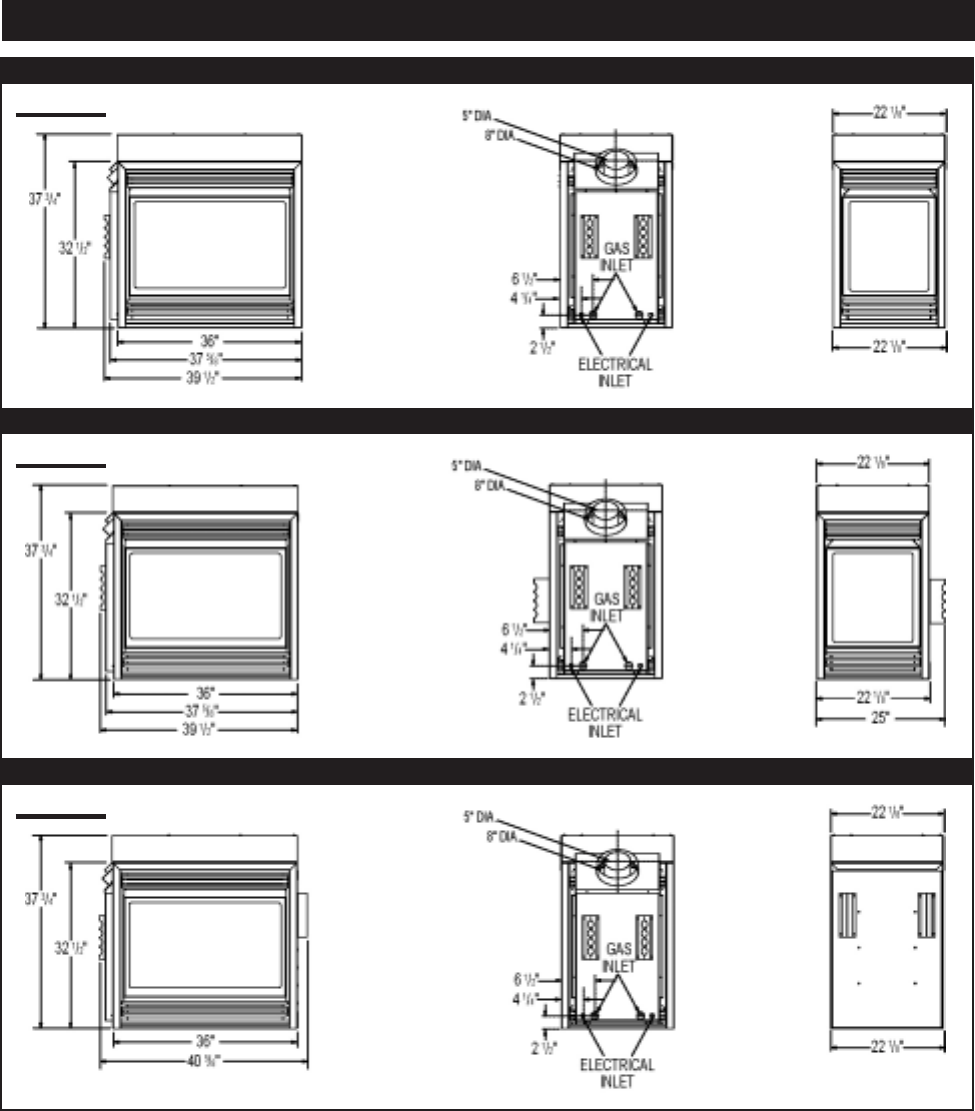
DIMENSIONS
SEE-THRU
PENINSULA
OPEN-END
FIGURE 1a
FIGURE 1b
FIGURE 1c

6
W415-0299 / C / 03.12.03
Use only Wolf Steel or Simpson Dura-Vent Model DV-GS
venting components. Minimum and maximum vent lengths,
for both horizontal and vertical installations, and air termi-
nal locations for either system are set out in this manual
and must be adhered to. For Simpson Dura-Vent, follow
the installation procedure provided with the venting com-
ponents.
When using Wolf Steel venting components, use only ap-
proved Wolf Steel rigid / flexible components with the fol-
lowing termination kits: WALL TERMINAL KIT GD422, or
1/12 TO 7/12 PITCH ROOF TERMINAL KIT GD410, 8/12 TO
12/12 ROOF TERMINAL KIT GD411, FLAT ROOF TERMI-
NAL KIT GD412 or PERISCOPE KIT GD401 (for wall pen-
etration below grade). With flexible venting, in conjunction
with the various terminations, use either the 5 foot vent kit
GD420 or the 10 foot vent kit GD430.
Wolf Steel rigid and flexible venting systems must not
be combined.
Wolf Steel and Simpson Dura-Vent venting systems
must not be combined.
These vent kits allow for either horizontal or vertical venting
of the fireplace. The maximum allowable horizontal run is
20 feet. The maximum allowable vertical vent length is 40
feet. The maximum number of 5" vent connections is two
horizontally or three vertically (excluding the fireplace and
the air terminal connections) when using aluminum flex-
ible venting.
For optimum flame appearance and fireplace perform-
ance, keep the vent length and number of elbows to a
minimum.
The air terminal must remain unobstructed at all times.
Examine the air terminal at least once a year to verify
that it is unobstructed and undamaged.
Purge all gas lines with the glass door of the fireplace
open. Assure that a continuous gas flow is at the burner
before closing the door.
Under extreme vent configurations, allow several minutes
(5-15) for the flame to stabilize after ignition.
Nine (9") inches is the minimum bend radius allowed
for the 8" diameter flexible liner.
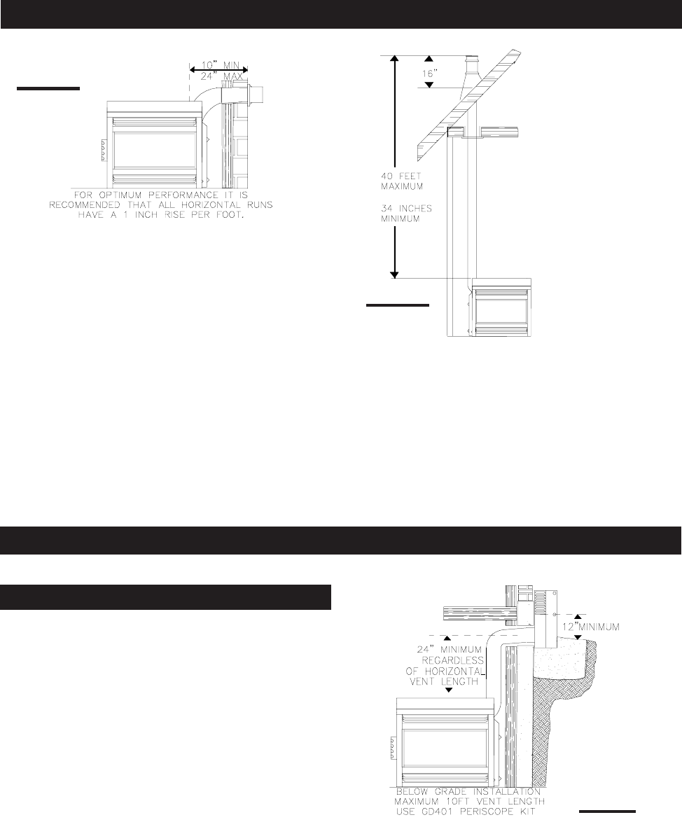
For optimum performance it is recommended that all
horizontal runs have a 1 inch rise per foot when using
Napoleon flexible vent components.
A terminal shall not terminate directly above a sidewalk
or paved driveway which is located between two sin-
gle family dwellings and serves both dwellings. Local
codes or regulations may require different clearances.
Do not allow the inside liner to bunch up on horizontal or
vertical runs and elbows. Keep it pulled tight. A 1¼" air
gap all around between the inner liner and outer liner is
required for safe operation. Use a firestop when pen-
etrating interior walls, floor or ceiling.
Horizontal runs may have a 0 inch rise per foot in all
cases using SIMPSON DURA-VENT or NAPOLEON
RIGID OR FLEXIBLE venting components when vent-
ing.
A clearance to combustibles of 1" all around the vent
pipe is required.
VENTING
VENTING LENGTHS
7
W415-0299 / C / 03.12.03
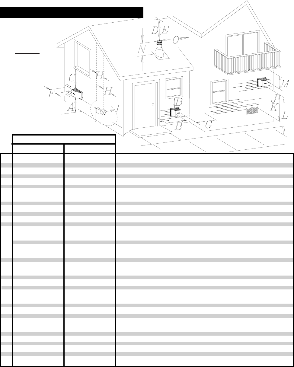
AIR TERMINAL INSTALLATIONS
*
*
* Recommended to prevent condensation on windows and thermal breakage
****
****
** It is recommended to use a heat shield and to maximize the distance to vinyl clad soffits.
******
******
*** The periscope GD-201 requires a minimum 18 inches clearance from an inside corner.
********
********
**** This is a recommended distance. For additional requirements check local codes.
††
††
† Three feet above if within 10 feet horizontally.
‡‡
‡‡
‡ A vent shall not terminate directly above a sidewalk or paved driveway that is located between two single f
a
dwellings and serves both dwellings.
† †† †
† †† †
† † Permitted only if the veranda, porch, or deck is fully open on a minimum of two sides beneath the floor.
† *† *
† *† *
† * Recommenced to prevent recirculation of exhaust products. For additional requirements check local code
s
A
B
C
D
E
F
G
H
I
J
K
L
M
N
O
12 INCHES
9 INCHES
12 INCHES*
18 INCHES**
12 INCHES**
0 INCHES
0 INCHES***
2 INCHES***
3 FEET****
3 FEET****
9 INCHES
3 FEET†
7 FEET****
12 INCHES****
16 INCHES
2 FEET†*
Clearance above grade, veranda porch, deck or balcony.
Clearance to windows or doors that open.
Clearance to permanently closed windows.
Vertical clearance to ventilated soffit located above the terminal within
a horizontal distance of 2 feet from the centerline of the terminal.
Clearance to unventilated soffit.
Clearance to an outside corner wall.
Clearance to an inside non-combustible corner wall or protruding
non-combustible obstructions (chimney, etc.).
Clearance to an inside combustible corner wall or protruding com-
bustible obstructions ( vent chase, etc.).
Clearance to each side of the centerline extended above the meter
/ regulator assembly to a maximum vertical distance of 15ft.
Clearance to a service regulator vent outlet.
Clearance to a non-mechanical air supply inlet to the building or a
combustion air inlet to any other appliance.
Clearance to a mechanical air supply inlet.
Clearance above a paved sidewalk or paved driveway located on
public property unless fitted with a heat shield kit GD-301.
Clearance under a veranda, porch, deck or balcony.
Clearance above the roof.
Clearance from an adjacent wall including neighbouring buildings.
CANADIAN U.S.A.
12 INCHES
12 INCHES
12 INCHES*
18 INCHES**
12 INCHES**
0 INCHES
0 INCHES***
2 INCHES***
3 FEET
3 FEET
12 INCHES
6 FEET
7 FEET‡
12 INCHES††
16 INCHES
2 FEET†*
INSTALLATIONS
FIGURE 2
8
W415-0299 / C / 03.12.03
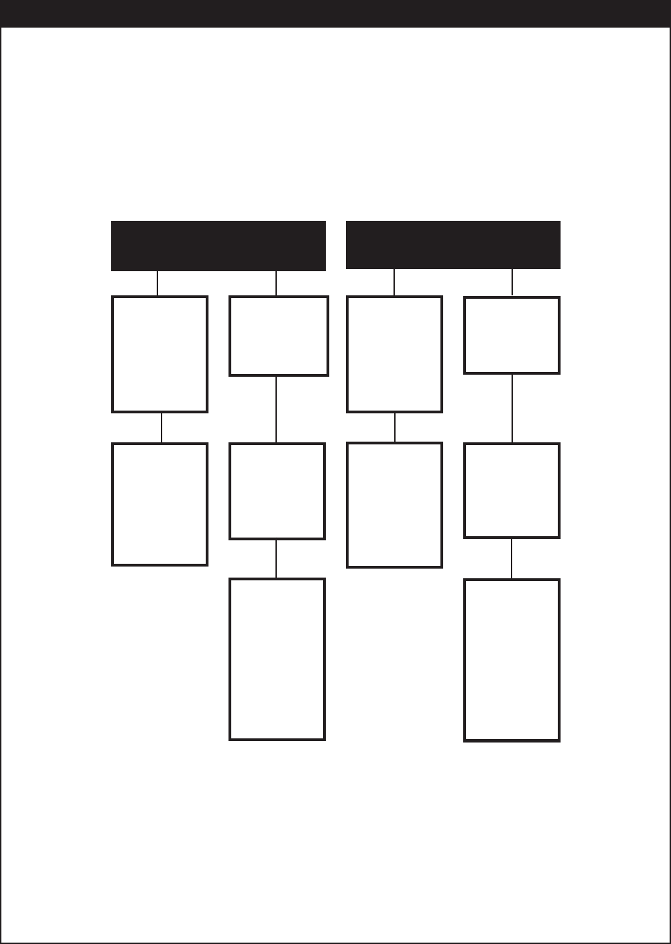
VENTING APPLICATION FLOWCHART
VERVER
VERVER
VERTICALTICAL
TICALTICAL
TICAL
TERMINTERMIN
TERMINTERMIN
TERMINAA
AA
ATIONTION
TIONTION
TION
HORIZONTHORIZONT
HORIZONTHORIZONT
HORIZONTALAL
ALAL
AL
TERMINTERMIN
TERMINTERMIN
TERMINAA
AA
ATIONTION
TIONTION
TION
vertical risevertical rise
vertical risevertical rise
vertical rise
is equal tois equal to
is equal tois equal to
is equal to
or greateror greater
or greateror greater
or greater
than thethan the
than thethan the
than the
horizontalhorizontal
horizontalhorizontal
horizontal
runrun
runrun
run
horizontalhorizontal
horizontalhorizontal
horizontal
run + verti-run + verti-
run + verti-run + verti-
run + verti-
cal rise tocal rise to
cal rise tocal rise to
cal rise to
maximummaximum
maximummaximum
maximum
of 40 feetof 40 feet
of 40 feetof 40 feet
of 40 feet
vertical risevertical rise
vertical risevertical rise
vertical rise
is less thanis less than
is less thanis less than
is less than
horizontalhorizontal
horizontalhorizontal
horizontal
runrun
runrun
run
horizontalhorizontal
horizontalhorizontal
horizontal
run + verti-run + verti-
run + verti-run + verti-
run + verti-
cal rise tocal rise to
cal rise tocal rise to
cal rise to
maximum ofmaximum of
maximum ofmaximum of
maximum of
24.75 feet24.75 feet
24.75 feet24.75 feet
24.75 feet
4.2 times4.2 times
4.2 times4.2 times
4.2 times
the verticalthe vertical
the verticalthe vertical
the vertical
rise equal torise equal to
rise equal torise equal to
rise equal to
or greateror greater
or greateror greater
or greater
than thethan the
than thethan the
than the
horizontalhorizontal
horizontalhorizontal
horizontal
runrun
runrun
run
verticalvertical
verticalvertical
vertical
rise is lessrise is less
rise is lessrise is less
rise is less
than hori-than hori-
than hori-than hori-
than hori-
zontal runzontal run
zontal runzontal run
zontal run
horizontalhorizontal
horizontalhorizontal
horizontal
run + verti-run + verti-
run + verti-run + verti-
run + verti-
cal rise tocal rise to
cal rise tocal rise to
cal rise to
maximummaximum
maximummaximum
maximum
of 40 feetof 40 feet
of 40 feetof 40 feet
of 40 feet
3 times the3 times the
3 times the3 times the
3 times the
vertical risevertical rise
vertical risevertical rise
vertical rise
equal to orequal to or
equal to orequal to or
equal to or
greatergreater
greatergreater
greater
than thethan the
than thethan the
than the
horizontalhorizontal
horizontalhorizontal
horizontal
runrun
runrun
run
9
W415-0299 / C / 03.12.03
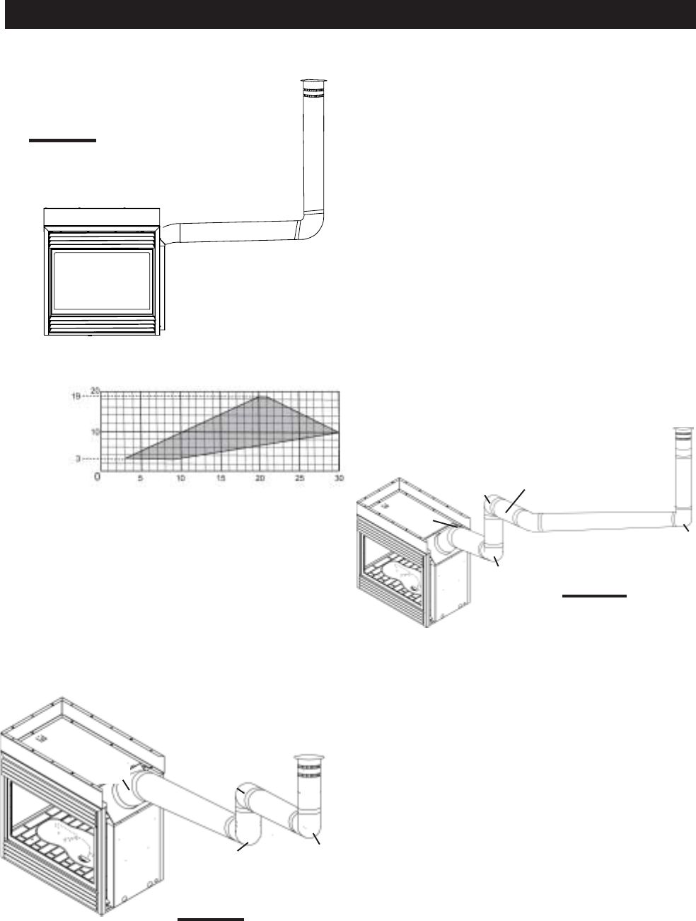
Use the GD401 periscope kit to locate the air termination
above grade. The periscope must be installed so that when
final grading is completed, the bottom air slot is located a
minimum of 12 inches above grade. The maximum allow-
able vent length depends on the model of fireplace, as
illustrated.
When venting, the horizontal run must be kept to a mini-
mum of 10 inches or a maximum of 20 feet. If a 20 foot
horizontal run is required, the fireplace must have a mini-
mum vertical rise immediately off the fireplace of 57 inches.
FIGURE 3a.
FIGURE 3a
FIGURE 4
FIGURE 3b
When terminating
vertically, the vertical
rise is a minimum 34
inches and a maxi-
mum 40 feet above
the fireplace. FIGURE
3b.
TYPICAL VENT INSTALLATIONS
SPECIAL VENT INSTALLATIONS
PERISCOPE TERMINATION
10
W415-0299 / C / 03.12.03
REQUIRED
VERTICAL
RISE IN FEET
(VT)
CALCULATED HORIZONTAL VENT RUN
PLUS OFFSETS IN FEET (HT)
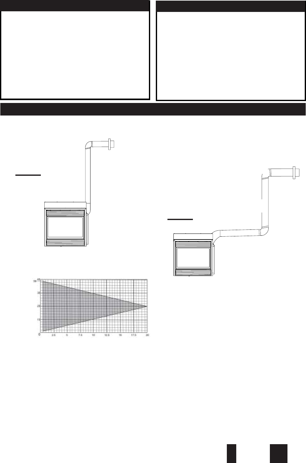
FIGURE 5
45º
FIGURE 6
90°
H1
H2
when (HT) < (VT)
Simple venting configuration (only one 45º and 90° elbow)
for the following symbols used in the venting calcula-
tions and examples are:
>- greater than
>- equal to or greater than
<- less than
<- equal to or less than
HT- total of both horizontal vent lengths (HR) and off-
sets (HO) in feet
HR- combined horizontal vent lengths in feet
HO- offset factor: .03(total degrees of offset - 135°**
**
*) in
feet
VT- combined vertical vent lengths in feet
feet inches
1° 0.03 0.5
15° 0.45 6.0
30° 0.9 11.0
45°**
**
*1.35 16.0
90°**
**
*2.7 32.0
* *
* *
* the first 45º and 90° offset has a zero value and is
shown in the formula as -45° and -90º respectively or
-135º when combined.
For vent configurations requiring more than one 45º and
90° elbow, the following formulas apply:
Formula 1: H
T
< V
T
Formula 2: H
T
+ V
T
< 40 feet
Example 1:
V
1
=8 ft
VT=
V
1
= 8 ft
H
1
= 2.5 ft
H
2
=2 ft
H
R
=H
1
+ H
2
= 2.5 + 2 = 4.5 ft
H
O
=.
03(one 45º elbow + two 90º elbows - 135º)
=0.3(225-135º) = 2.7ft
H
T
=H
R
+ H
O
= 4.5 + 2.7 = 7.2 ft
H
T
+ V
T
= 7.2 +8 =15.2ft
Formula 1: H
T
< V
T
7.2 < 8
Formula 2: H
T
+ V
T
< 40 feet
15.2 < 40
45º
90°
Since both formulas are met, this vent configuration is ac-
ceptable.
V1
90°
The shaded area within the lines represents acceptable
values for HT and VT .
DEFINITIONS ELBOW VENT LENGTH VALUES
HORIZONTAL TERMINATION
HT- total of both horizontal vent lengths (HR) and offsets
(HO) in feet
11
W415-0299 / C / 03.12.03
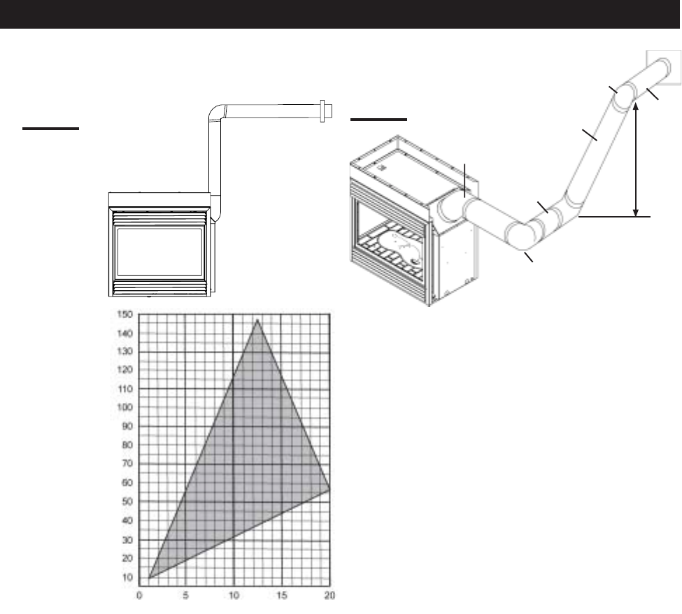
See graph to determine the re-
quired vertical rise VT for the required
horizontal run HT.
For vent configurations requiring more than one 45º and
90° elbow the following formulas apply:
Formula 1: HT < 4.2 VT
Formula 2: HT + VT < 24.75 feet
FIGURE 7
REQUIRED
VERTICAL
RISE IN
INCHES (VT)
HORIZONTAL VENT RUN PLUS OFFSETS IN FEET (HT)
when (HT) > (VT)
Simple venting configuration (only one 45º and 90° elbow)
Example 2:
V
1
=4 ft
VT=V1 = 4 ft
H
1
=2 ft
H
2
=1 ft
H
3
=1 ft
H
4
= 1.5 ft
HR=H1 + H2 + H3 + H4 = 2 + 1 + 1 + 1. 5 = 5.5 ft
H
O
= .03(one 45º elbow + three 90º elbow -135º)
=.03(315-135)=5.4ft
H
T
=H
R
+ H
O
= 5.5 +5.4 = 10.9 ft
H
T
+ V
T
= 10.9 + 4 = 14.9 ft
Formula 1: H
T
< 4.2 V
T
4.2 VT = 4.2 x 4 = 16.8 ft
10.9 < 16.8
Formula 2: H
T
+ V
T
< 24.75 feet
14.9 < 24.75
Since both formulas are met, this vent configuration is ac-
ceptable.
H4
V1
90°
H3
H1
90°
H2
90°
FIGURE 8
45°
The shaded area within the lines represents acceptable
values for HT and VT .
HORIZONTAL TERMINATION
12
W415-0299 / C / 03.12.03
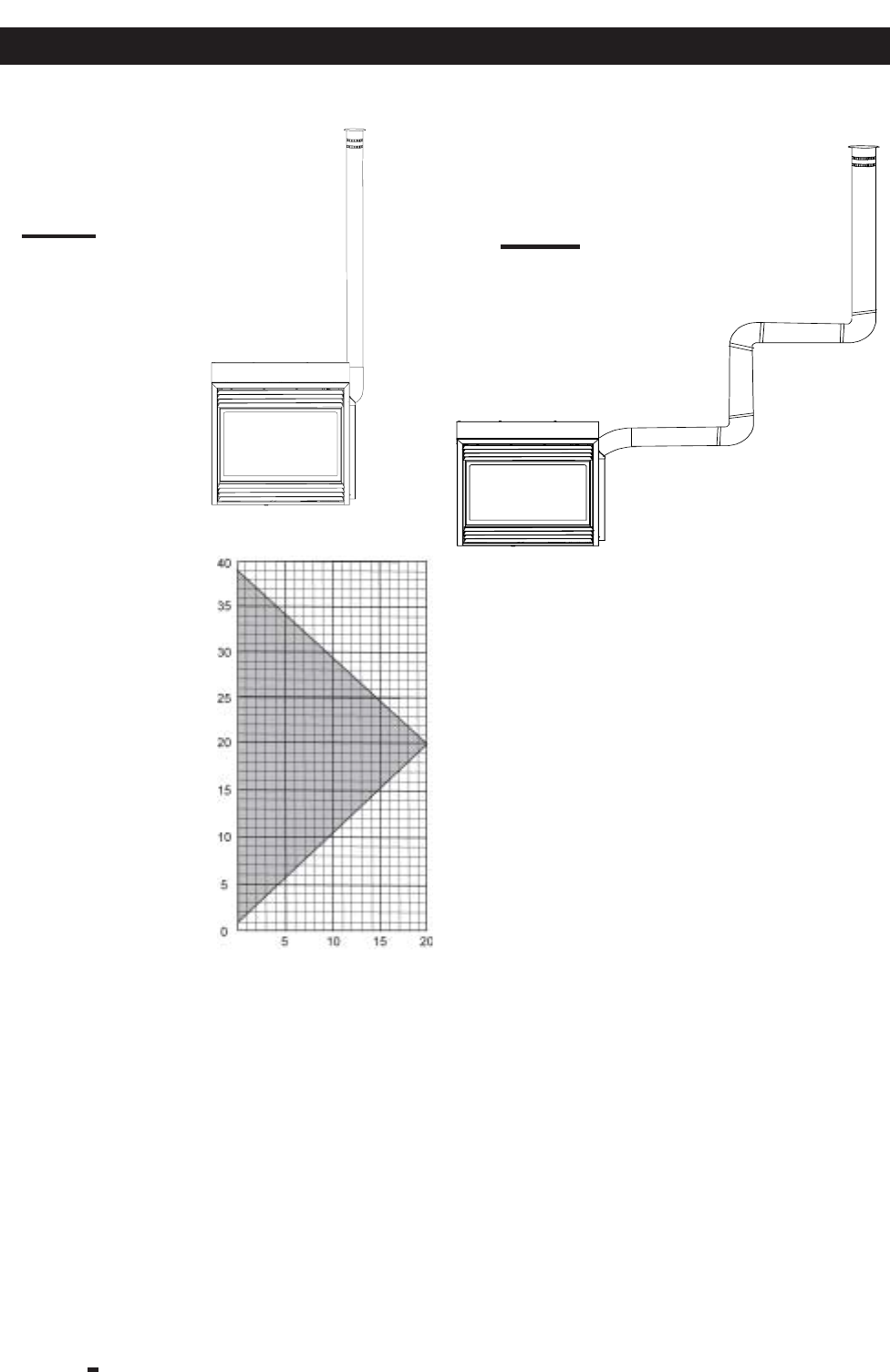
Example 3:
V
1
=5 ft
V
2
= 10 ft
VT=
V
1
+
V
2
=
5 + 10 = 15 ft
H
1
=3 ft
H
2
= 2.5 ft
HR=H1 + H2 = 3 + 2.5 = 5.5 ft
HO= .03(one 45º elbow + three 90º elbows - 135º)
= .03(45+90+90+90-135)=5.4
H
T
=H
R
+ H
O
= 5.5 + 5.4 = 10.9 ft
H
T
+ V
T
= 10.9 + 15 = 25.9 ft
Formula 1: H
T
< V
T
10.9 < 15
Formula 2: H
T
+ V
T
< 40 feet
25.9 < 40
Since both formulas are met, this vent configuration is ac-
ceptable.
when (HT) < (VT)
Simple venting configurations
FIGURE 9
REQUIRED VERTICAL RISE IN
FEET (VT)
HORIZONTAL VENT RUN
PLUS OFFSETS IN FEET (HT)
FIGURE10
For vent configurations requiring more than one 45º and
one 90° elbow , the following formulas apply:
Formula 1: H
T
< V
T
Formula 2: H
T
+ V
T
< 40 feet
See graph to determine the required vertical rise VT for the
required horizontal run HT.
90°
90°
V1
H1
H2
V2
45°
45°
90°
The shaded area within the lines represents acceptable
values for HT and VT.
VERTICAL TERMINATION
13
W415-0299 / C / 03.12.03
For vent configurations requiring more than one 45º and
one 90° elbow , the following formulas apply:
Formula 1: H
T
< 3V
T
Formula 2: H
T
+ V
T
< 40 feet
Example 4:
when (HT) > (VT)
Simple venting configurations
See graph to determine the required vertical rise VT for the
required horizontal run HT.
V
1
=1 ft
V
2
= 1.5 ft
VT=
V
1
+
V
2
=
1 + 1.5 = 2.5 ft
H
1
=6 ft
H
2
=2 ft
HR=H1 + H2 = 6 + 2 = 8 ft
HO= .03(one 45º elbow + three 90º elbow - 135º)
= .03(45 + 90 + 90 + 90 - 135) = 5.4 ft
H
T
=H
R
+ H
O
= 8 + 5.4 = 13.4 ft
H
T
+ V
T
= 13.4 + 2.5 = 15.9 ft
Formula 1: H
T
< 3V
T
3VT=
3 x
2.5 = 7.5 ft
13.4 > 7.5
Since this formula is not met, this vent configuration is
unacceptable.
Formula 2: H
T
+ V
T
< 40 feet
15.9 < 40
Since only formula 2 is met, this vent configuration is unac-
ceptable and a new fireplace location or vent configuration
will need to be established to satisfy both formulas.
Example 5:
V
1
= 1.5 ft
V
2
=8 ft
VT=
V
1
+
V
2
=
1.5 + 8= 9.5 ft
H
1
=1 ft
H
2
=1 ft
H
3
= 10.75 ft
HR=H1 + H2 + H3 = 1 + 1 + 10.75 = 12.75 ft
HO= .03(three 90° elbows + two 45° elbow - 135°)
= .03(90 + 90 + 90 + 45 + 45 - 135) = 6.75 ft
H
T
=H
R
+ H
O
= 12.75 + 6.75 = 19.5 ft
H
T
+ V
T
= 19.5 + 4.5= 29 ft
Formula 1: H
T
< 3V
T
3VT =
3 x
9.5 = 28.5 ft
19.5 < 28.5
Formula 2: H
T
+ V
T
< 40 feet
29 < 40
Since both formulas are met, this vent configuration is ac-
ceptable.
REQUIRED
VERTICAL
RISE IN
FEET (VT)
HORIZONTAL VENT RUN PLUS OFFSET IN FEET (HT)
FIGURE 13
FIGURE 11
45°
45°
90°
90°
H1
V1
H2
90°
V2
H3
The shaded area within the lines represents acceptable
values for HT and VT.
H2
90°
90° V2
45°
H1
V1
90°
FIGURE 12
VERTICAL TERMINATION
14
W415-0299 / C / 03.12.03
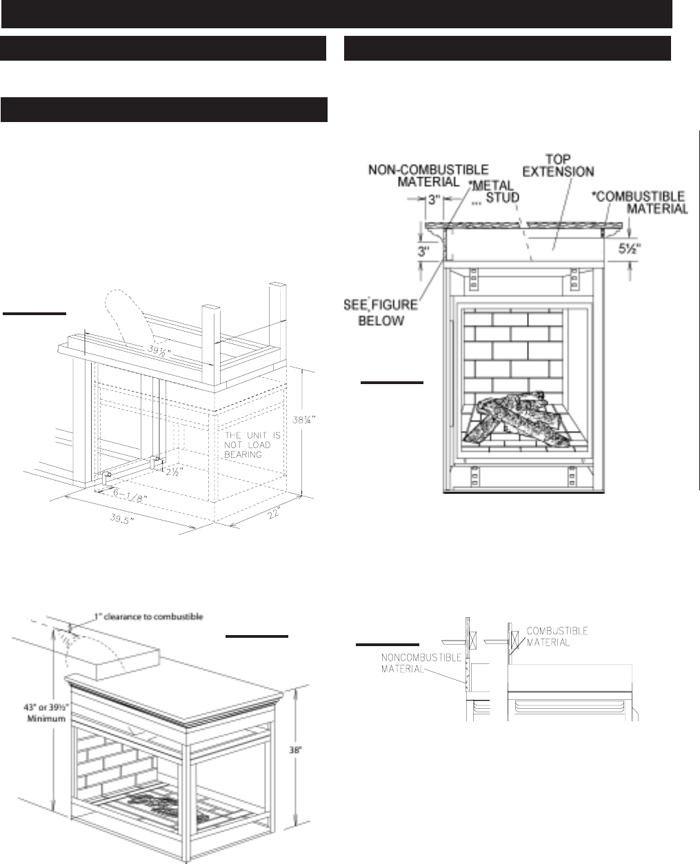
When finishing the fireplace, combustible material may
rest directly on of the top extension. In order to achieve a
countertop or bar type appearance with the minimum height
allowed, framing must be non-combustible and may be
done with metal studding attached to the top extension
sides or the upper frame of the fireplace.
fer to pages 6-13. All venting must have a minimum clear-
ance of 1" to combustible.
See Page 18 for additional framing dimensions.
Note: In order to avoid the possibility of exposed
insulation or vapour barrier coming in contact with the
fireplace body, it is recommended that the walls of the
fireplace enclosure be “finished” (ie: drywall/sheetrock),
as you would finish any other outside wall of a home. This
will ensure that clearance to combustibles is maintained
within the cavity.
It is best to frame your fireplace after it is positioned and
the vent system is installed. Use 2x4's and frame to local
building codes.
To install the fireplace face flush with the finished wall,
position the framework to accommodate the thickness
of the finished wall.
Care should be taken to maintain sufficient clearance for
the vent installation. A horizontal vent installation requires
a minimum height of 39½" using rigid or 43" using flexible
vent pipe. (including the 1" clearance to combustibles).
A
FIGURE 14
TOP OF THE UNIT
TOP EXTENTION
FIGURE 17
FIGURE 15
A = 22 " minus finishing material thickness each side.
FIGURE 16
* The top extension may be removed if non-combustible
framing is faced with a non-combustible material placed
flush with the front face of the unit and extending from the
top of the unit. (Example: cement board) (not supplied).
Combustible counter / bar tops must maintain a minimum
of 38 inches from the base of the fireplace to the underside
of the top.
NOTE: Wolf Steel trim and/or surround kits will not to-
tally cover the top extension of the fireplace. In order to
obtain a smooth transition from the trim / surround to the
wall, it is recommended that the top extension be re-
moved and the unit be installed following the above pro-
cedure.
PENINSULA INSTALLATION PROCEDURE
VENTING
FRAMING
COUNTERTOP / BAR INSTALLATION
15
W415-0299 / C / 03.12.03
Combustible materials may be installed flush with the front
of the fireplace but must not cover any of the black face-
areas of the fireplace. Non-combustible material (brick,
stone or ceramic tile) may protrude in these areas.
It is not necessary to install a hearth extension with this
fireplace system.
When roughing in the fireplace, raise the fireplace to ac-
commodate for the thickness of the finished floor materi-
als, i.e. tile, carpeting, hard wood, which if not planned for
will interfere with the opening of the lower access door and
the installation of many decorative flashing accessories.
Objects placed in front of the fireplace should be
kept a minimum of 48" away from the glass front
faces.
Refer to pages 22-25 for complete instructions regarding
mantle requirements and installations, log placement,
glass door and upper and lower louvre attachments.
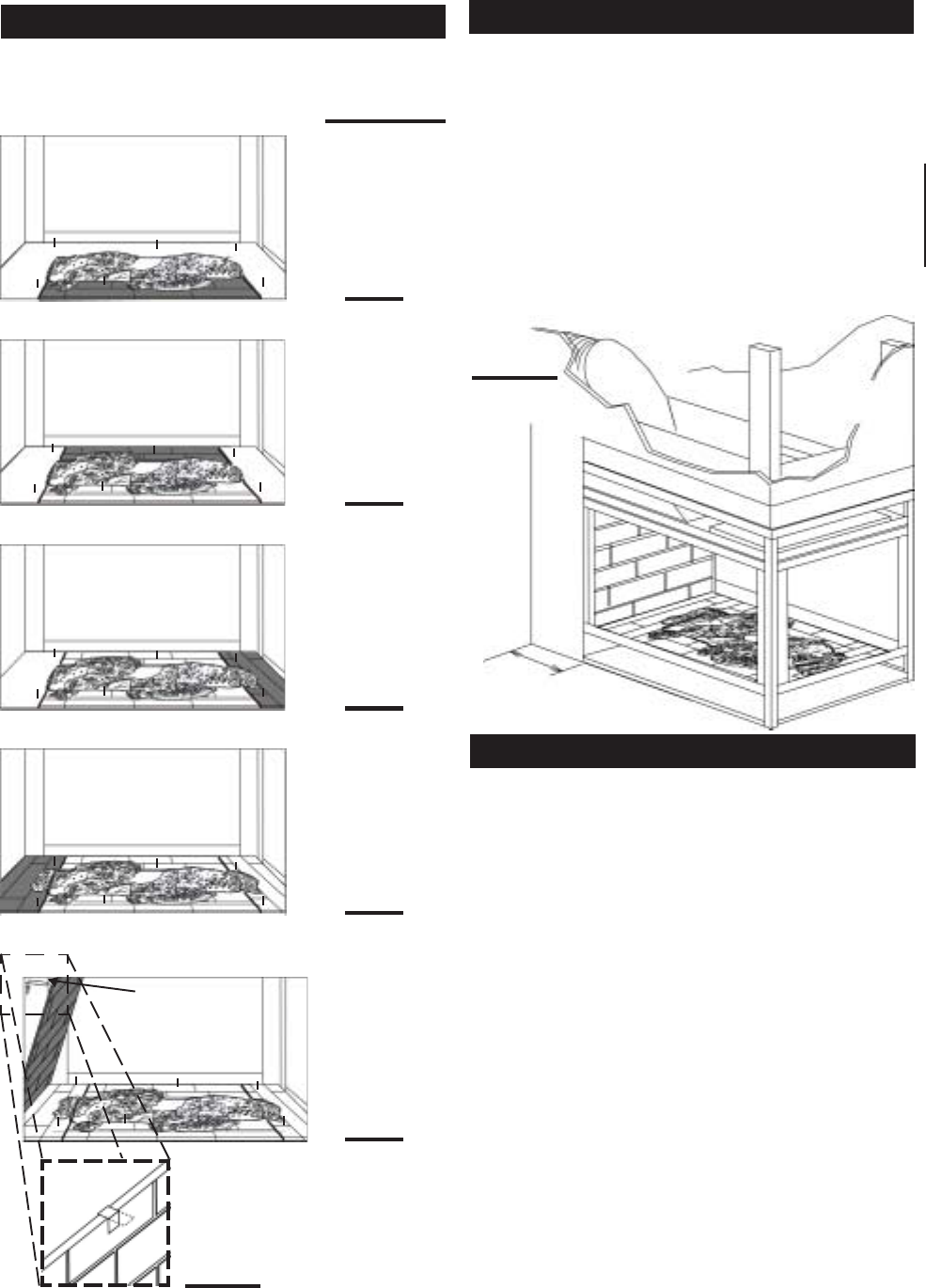
Install the base panels as illustrated in steps 1-4 . The
side panel sits under the bracket tab. Holding the side
panel in position, bend down the tab to secure. DETAIL 5.
FIGURES 18a-e
FIGURE 19
DRYWALL DRYWALL
5" MIN
RETAINER
DETAIL 5
STEP 3
STEP 2
STEP 1
STEP 4
STEP 5
BRICK PANEL INSTALLATION FACING
FINISHING
16
W415-0299 / C / 03.12.03
Refer to pages 6-13. All venting must have a minimum
clearance of 1" to combustible.
See Page 18 for additional framing dimensions.
Note: In order to avoid the possibility of exposed
insulation or vapour barrier coming in contact with the
fireplace body, it is recommended that the walls of the
fireplace enclosure be “finished” (ie: drywall/sheetrock),
as you would finish any other outside wall of a home. This
will ensure that clearance to combustibles is maintained
within the cavity.
It is best to frame your fireplace after it is positioned and
the vent system is installed. Use 2x4's and frame to local
building codes.
NOTE: LEFT CORNER UNIT ILLUSTRATED
To install the fireplace face flush with the finished wall,
position the framework to accommodate the thickness
of the finished wall.
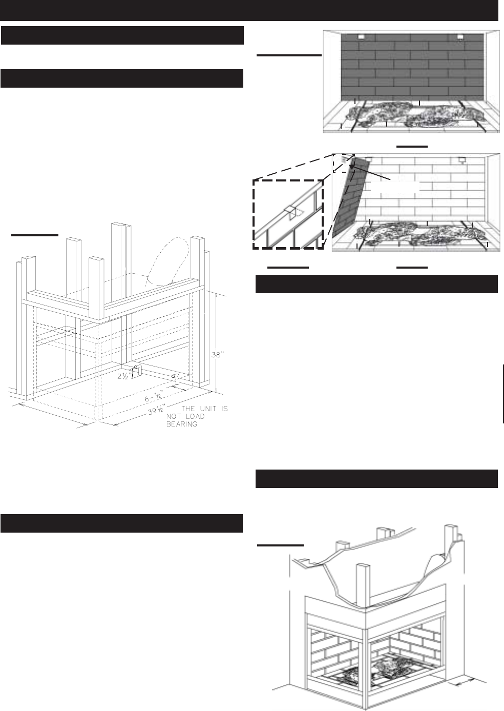
Install the base panels as illustrated in steps 1-4 on page
15. The side panel sits under the bracket tab. Holding the
side panel in position, bend down the tab to secure. DE-
TAIL 6.
A
A = 25¼" minus finishing material thickness each side.
FIGURES 21a-c
FIGURE 20
Combustible materials may be installed flush with the front
of the fireplace but must not cover any of the black face-
areas of the fireplace. Non-combustible material (brick,
stone or ceramic tile) may protrude in these areas.
It is not necessary to install a hearth extension with this
fireplace system.
When roughing in the fireplace, raise the fireplace to ac-
commodate for the thickness of the finished floor materi-
als, i.e. tile, carpeting, hard wood, which if not planned for
will interfere with the opening of the lower access door and
the installation of many decorative flashing accessories.
Objects placed in front of the fireplace should be
kept a minimum of 48" away from the glass front
faces.
Refer to pages 22-25 for complete instructions regarding
mantle requirements and installations, log placement,
glass door and upper and lower louvre attachments.
STEP 6
RETAINER
DETAIL 6
STEP 5
DRYWALL
5" MIN
DRYWALL
FIGURE 22
OPEN-END INSTALLATION PROCEDURE
BRICK PANEL INSTALLATION
VENTING
FRAMING
FACING
FINISHING
17
W415-0299 / C / 03.12.03
Refer to pages 6-13. All venting must have a minimum
clearance of 1" to combustible.
See Page 18 for additional framing dimensions.
Note: In order to avoid the possibility of exposed
insulation or vapour barrier coming in contact with the
fireplace body, it is recommended that the walls of the
fireplace enclosure be “finished” (ie: drywall/sheetrock),
as you would finish any other outside wall of a home.
This will ensure that clearance to combustibles is
maintained within the cavity.
A
A = 22" minus finishing material thickness, each side.
FIGURE 23
FIGURES 24a-c
Install the base panels as illustrated in steps 1-4 on page
15. Both side panels sit under the bracket tab. Holding the
side panel in position, bend down the tab to secure. DE-
TAIL 6.
RETAINER
RETAINER
STEP 5
STEP 6
DETAIL 5 & 6
Combustible materials may be installed flush with the front
of the fireplace but must not cover any of the black face-
areas of the fireplace. Non-combustible material (brick,
stone or ceramic tile) may protrude in these areas.
It is not necessary to install a hearth extension with this
fireplace system.
When roughing in the fireplace, raise the fireplace to ac-
commodate for the thickness of the finished floor materi-
als, i.e. tile, carpeting, hard wood, which if not planned for
will interfere with the opening of the lower access door and
the installation of many decorative flashing accessories.
Objects placed in front of the fireplace should be
kept a minimum of 48" away from the glass front
faces.
Refer to pages 22-25 for complete instructions regarding
mantle requirements and installations, log placement,
glass door and upper and lower louvre attachments.
DRYWALL
DRYWALL
5" MIN
FIGURE 25
SEE-THROUGH INSTALLATION PROCEDURE
VENTING
FRAMING
BRICK PANEL INSTALLATION
FACING
FINISHING
18
W415-0299 / C / 03.12.03
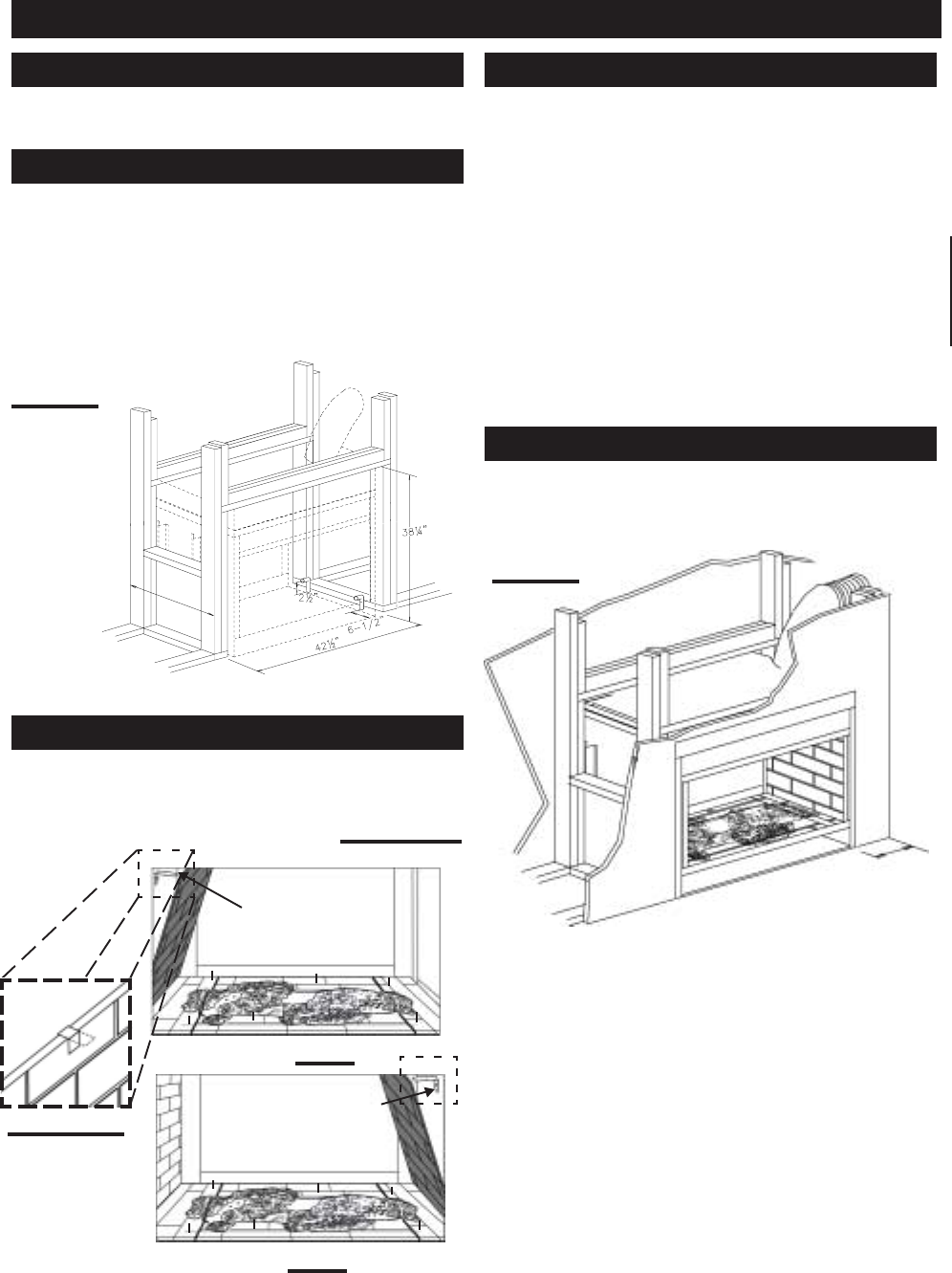
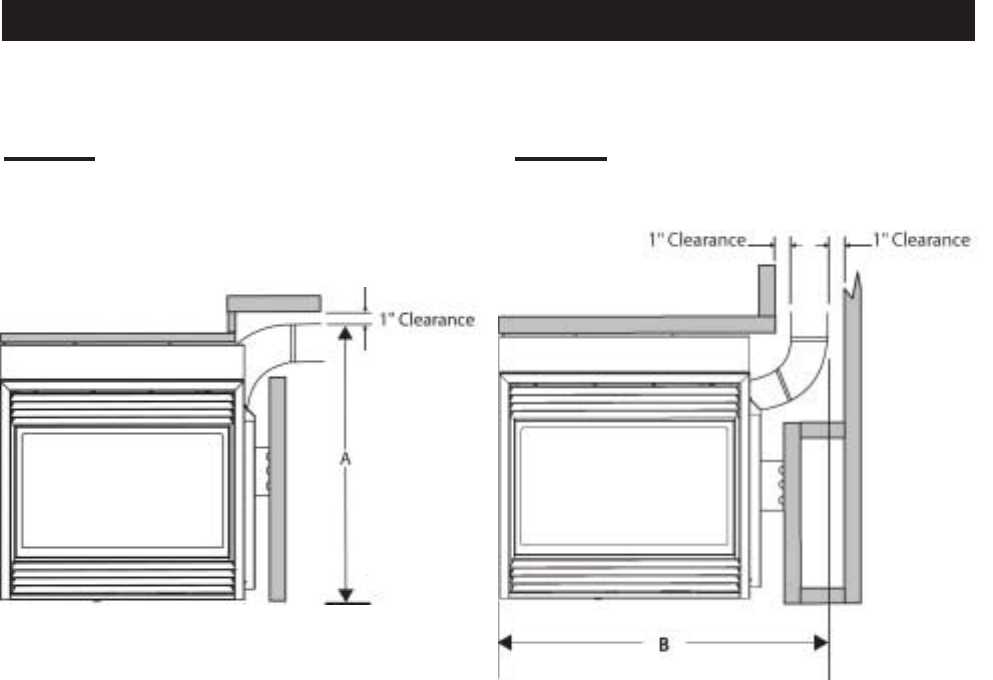
There must be a minimum of 1" clearance to combustibles
when framing around all venting options. See pages 14-17.
FIGURE 26 FIGURE 27
Horizontal Vent Off Fireplace Vertical Vent Off Fireplace
A = 42" using flexible vent components.
A = 38½" using Wolf Steel rigid vent components.
B = 45" using flexible vent components.
B = 42½" using Wolf Steel rigid vent components.
VENT FRAMING DIMENSIONS
19
W415-0299 / C / 03.12.03
For optimum performance it is recommended that all
horizontal runs have a minimum 1 inch rise per foot us-
ing flexible venting.
For safe and proper operation of the fireplace, follow the
venting instructions exactly.
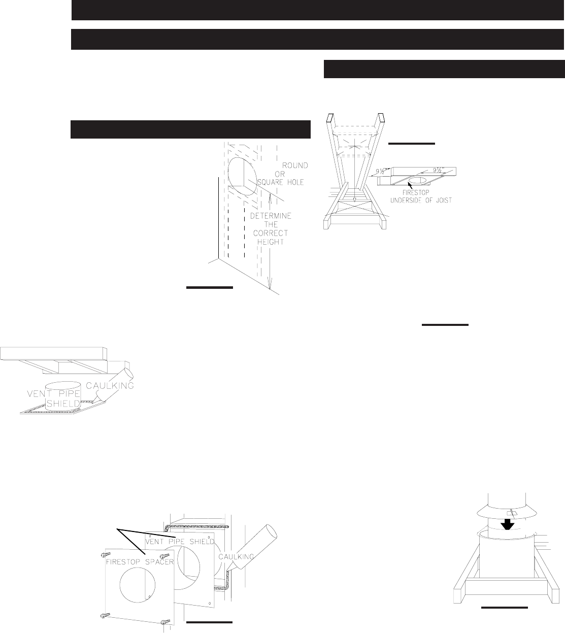
This application occurs when
venting through an exterior wall.
Having determined the air termi-
nal location, cut and frame a hole
in an exterior wall with a mini-
mum square or round opening
of 10½"**
**
*. (As an alternative to
framing, a vent pipe shield may
be installed, ensuring a 1" clear-
ance to combustibles.
Mark and cut the vent pipe shield to the determined depth
of the combustible wall. Apply a bead of caulking (not sup-
plied) to the framework or to the shield plate (in the case of
a finished wall) and secure the shield through the opening
to the interior wall. The final location of the vent pipe shield
should maintain the required clearance to the 8" vent
pipe / liner. Do not fill this cavity with any type of material.
Apply a bead of caulking all around and place a firestop
spacer over the vent shield to restrict cold air from being
drawn into the room or around the fireplace. Ensure that
both spacer and shield maintain the required clearance to
combustibles. Once the vent pipe / liner is installed in its
final position, apply sealant between the pipe / liner and
the firestop spacer.
FIGURE 29
OR
This application occurs when venting through a roof. In-
stallation kits for various roof pitches are available from
your Napoleon dealer.
See Accessories to or-
der the specific kit re-
quired.
1. Determine the air ter-
minal location, cut and
frame 10½ inch open-
ings in the ceiling and
the roof to provide the
minimum clearance be-
tween the fireplace pipe
/ liner and any combus-
tible material. Try to center the exhaust pipe location mid-
way between two joist to prevent having to cut them. Use a
plumb bob to line up the center of the openings.
DO NOT FILL THIS
SPACE WITH ANY
TYPE OF MATERIAL.
A vent pipe shield will
prevent any materi-
als such as insula-
tion, from filling up
the 1" air space
around the pipe. Nail headers between the joist for extra
support.
2. Apply a bead of caulking (not supplied) to the framework
or to the Wolf Steel vent pipe shield plate or equivalent (in
the case of a finished ceiling), and secure over the open-
ing in the ceiling. A firestop must be placed on the bottom
of each framed opening in a roof or ceiling that the venting
system passes through. Apply a bead of caulking all around
and place a firestop spacer over the vent shield to restrict
cold air from being drawn into the room or around the fire-
place. Ensure that both spacer and shield maintain the
required clearance to com-
bustibles. Once the vent
pipe / liner is installed in its
final position, apply sealant
between the pipe / liner and
the firestop spacer.
3. In the attic, after the pipe /
liner has been installed,
slide the vent pipe collar
down to cover up the open
end of the shield and tighten.
This will prevent any materi-
als, such as insulation, from
filling up the 1" air space around the pipe.
FIGURE 31
FIGURE 32
VENT PIPE
SHIELD
VENT
PIPE
COLLAR
FIGURE 28
**
**
*
FIGURE 30
INSTALLATION
WALL AND CEILING PROTECTION
HORIZONTAL INSTALLATION
VERTICAL INSTALLATION
10½"
20
W415-0299 / C / 03.12.03
For safe and proper operation of the fireplace, follow
the venting instructions exactly.
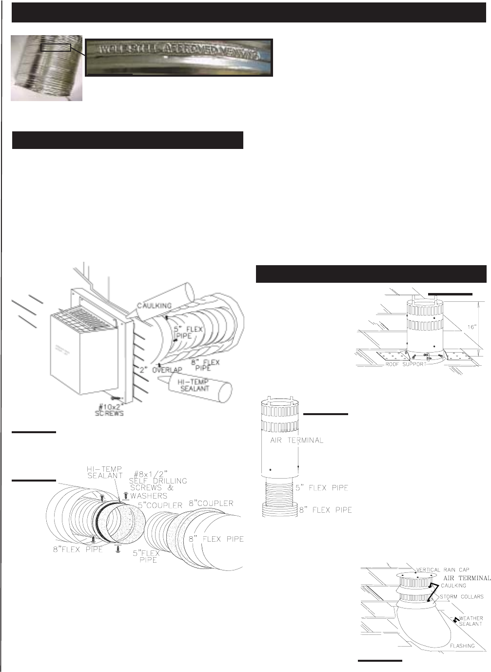
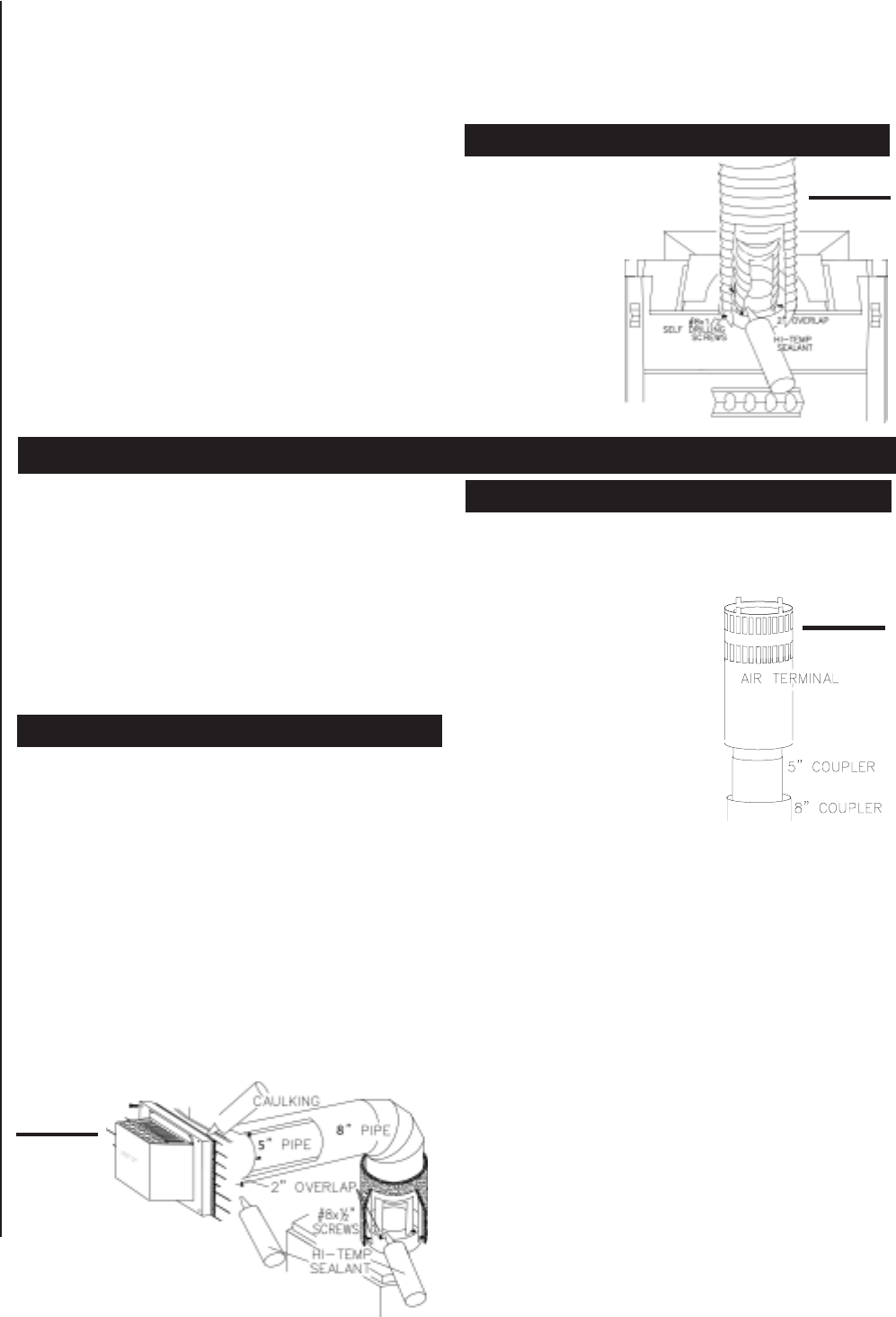
1. Stretch the 5" diameter aluminum flexible liner to the
required length taking into account the additional length
needed for the finished wall surface. Apply a heavy bead of
the high temperature sealant, supplied with the unit, to the
inside of the 5" liner approximately 1" from the end. Slip the
liner a minimum of 2" over the fireplace vent collar and
secure with 3 #8 screws.
2. Using the 8" diameter flexible aluminum liner, apply seal-
ant, slide a minimum of 2" over the fireplace combustion
air collar and secure with 3 #8 screws.
The air teminal may be recessed into the exterior wall
or siding by 1½", the depth of the return flange.
3. Insert the liners through the firestop. Position and se-
cure the fireplace using the nailing tabs (2 per side) and/or
secure to the floor using screws inserted through the two
¼" diameter holes in the front left and right corners of the
base. The liners should be flush with the exterior wall.
5. From outside, apply a bead of the high temperature seal-
ant to the inside of both liners, approximately 1" from the
end of each liner.
5. Holding the air terminal (lettering in an upright, readable
position), insert into both liners with a twisting motion to
ensure that both the terminal sleeves engage into the lin-
ers / sealant. Secure the terminal to the exterior wall and
make weather tight by sealing with caulking (not supplied).
6. If more liner needs to be used to reach the fireplace,
couple them together as illustrated. The vent system must
be supported approximately every 3 feet for both vertical
and horizontal runs. Use Napoleon support ring assembly
W010-0380 or equivalent noncombustible strapping to
maintain the minimum 1" clearance to combustibles.
1. Fasten the roof support
to the roof using the
screws provided. The roof
support is optional. In this
case the venting is to be
adequately supported us-
ing either an alternate
method suitable to the au-
thority having jurisdiction
or the optional roof support.
2. Stretch the 5" diameter alumi-
num flexible liner to the required
length. Slip the liner a minimum
of 2" over the inner sleeve of the
air terminal and secure with 3 #8
screws. Seal using a heavy bead
of the high temperature sealant.
3. Repeat using 8" diameter alu-
minum flexible liner.
5. Thread the air terminal pipe
assembly down through the roof.
The air terminal must be located
vertically and plumb. Attach the air terminal assembly to
the roof support, ensuring that a minimum 16" of air termi-
nal will penetrate the roof when fastened.
DO NOT CLAMP THE
FLEXIBLE ALUMINUM
LINER.
FIGURE 38
FIGURE 36
USING FLEXIBLE VENT COMPONENTS
Use only approved aluminum flexible liner kits marked:
"Wolf Steel Approved Venting" as identified by the stamp only on the 8” outer liner.
For optimum performance, it is recommended that
horizontal runs have a minimum ¼ inch rise per
foot .
FIGURE 33
HORIZONTAL AIR TERMINAL INSTALLATION
VERTICAL AIR TERMINAL INSTALLATION
FIGURE 34
FIGURE 35
FIGURE 37
21
W415-0299 / C / 03.12.03
FIGURE 40
FIGURE 39
1. Move the fireplace into position.
2. Fasten the roof support to the roof using the screws
provided. The roof support is optional. In this case the vent-
ing is to be adequately supported using either an alternate
method suitable to the authority
having jurisdiction or the optional
roof support.
3. Apply high temperature sealant
to the outer edge of the inner sleeve
of the air terminal. Slip a 5" diam-
eter coupler a minimum of 2" over
the sleeve and secure using 3
screws.
5. Apply high temperature sealant
to the outer edge of the of the out-
side sleeve of the air terminal. Slip
a 8" diameter coupler over the sleeve and secure as
before.Trim the 8" coupler even with the 5" coupler end.
5. Thread the air terminal pipe assembly down through the
roof support and attach, ensuring that a minimum 16" of
air terminal will penetrate the roof when fastened. If the
attic space is tight, we recommend threading the Wolf
Steel vent pipe collar or equivalent loosely onto the air
terminal assembly as it is passed through the attic.
The air terminal must be located vertically and plumb.
6. Remove nails from the shingles, above and to the sides
of the chimney. Place the flashing over the air terminal and
slide it underneath the sides and upper edge of the
shingles. Ensure that the air terminal is properly centered
within the flashing, giving a 3/5" margin all around. Fasten
to the roof. Do NOT nail through the lower portion of the
flashing. Make weather-tight by sealing with caulking. Where
possible, cover the sides and top edges of the flashing
with roofing material.
For optimum performance it is recommended that all
horizontal runs have a ¼ inch rise per foot.
For safe and proper operation of the fireplace, follow
the venting instructions exactly.
The vent system must be supported approximately every 3
feet for both vertical and horizontal runs. Use Napoleon
vent spacers W615-0033 every 3 feet and on either side of
each elbow to maintain the minimum 1¼" clearance be-
tween the outer and inner vent pipes. Use Napoleon sup-
port ring assembly W010-0380 or equivalent noncombus-
tible strapping to maintain the minimum 1" clearance to
combustibles for both vertical and horizontal runs.
1. Move the fireplace into position. Measure the vent
length required between terminal and fireplace taking into
account the additional length needed for the finished wall
surface and any 1¼" overlaps between venting compo-
nents.
2. Apply high temperature sealant to the outer edge of the
5" inner collar of the fireplace. Attach the first vent compo-
nent and secure using 3 self tapping screws. Repeat us-
ing 8" piping.
3. Holding the air terminal (lettering in an upright, readable
position), insert into both vent pipes with a twisting motion
to ensure that both the terminal sleeves engage into the
vent pipes and the sealant. Secure the terminal to the exte-
rior wall and make weather tight by sealing with caulking
(not supplied). The air teminal may be recessed into the
exterior wall or siding by 1½", the depth of the return
flange.
USING RIGID VENT COMPONENTS
5. Remove nails from the shingles, above and to the sides
of the chimney. Place the flashing over the air terminal and
slide it underneath the sides and upper edge of the
shingles. Ensure that the air terminal is properly centered
within the flashing, giving a 3/5" margin all around. Fasten
to the roof. Do not nail through the lower portion of the
flashing. Make weather-tight by sealing with caulking.
Where possible, cover the sides and top edges of the flash-
ing with roofing material.
6. Apply a heavy bead of weatherproof caulking 2 inches
above the flashing. Slide the storm collar around the air
terminal and down to the caulking. Tighten to ensure that a
weather-tight seal between the air terminal and the collar
is achieved. Attach the other storm collar centered between
the air intake and the air exhaust slots onto the air termi-
nal. Tighten securely. Attach the vertical rain cap.
Spacers are attached to the 5" inner flex liner at prede-
termined intervals to maintain a 1-1/5" air gap to the 8"
outer liner. These spacers must not be removed.
7. If more liner needs to be used to reach the fireplace,
couple them together as illustrated. The vent system must
be supported approximately every 3 feet for both vertical and
horizontal runs. Use Wolf Steel support ring assembly W010-
0370 or equivalent noncombustible strapping to maintain a
clearance to combustibles of 1".
HORIZONTAL AIR TERMINAL INSTALLATION
VERTICAL AIR TERMINAL INSTALLATION
FIREPLACE VENT CONNECTION
1. Install the 5 inch diameter
aluminum flexible liner to the fire-
place. Secure with 3 screws and
flat washers. Seal
the joint and screw
holes using the high
temperature sealant
provided.
2. Install the 8 inch
diameter aluminum
flexible liner to the
fireplace. Attach and
seal the joints.
FIGURE 41
22
W415-0299 / C / 03.12.03
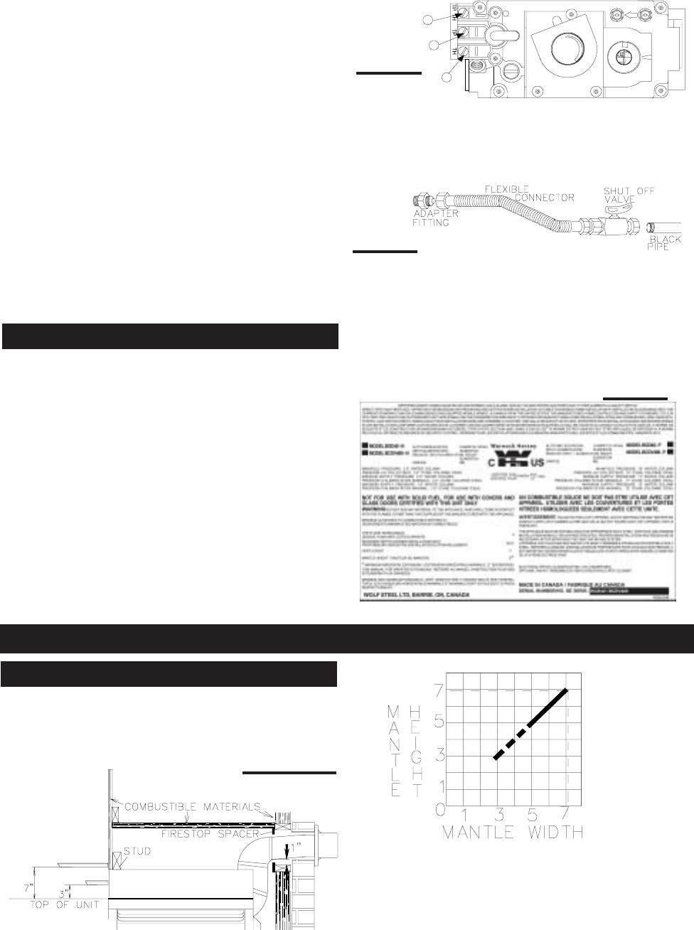
Do not connect either the wall switch, thermostat or
gas valve to electricity (110 volts).
Attach the two leads to terminals 1 and 3 located on the
gas valve.
4. Install the rigid black pipe, ½" type-L copper tubing or,
if local codes permit, a 3/8" flex connector and shutoff valve
to the gas line and the fireplace gas valve. Seal and tighten
securely. An adapter fitting is required between the gas
valve and the copper tubing or flex connector.
Do not kink flexible connector.
5. Check for gas leaks by brushing on a soap and water
solution.
Do not use open flame.
6. Mark the appropriate boxes on the rating plate label to
indicate the model type.
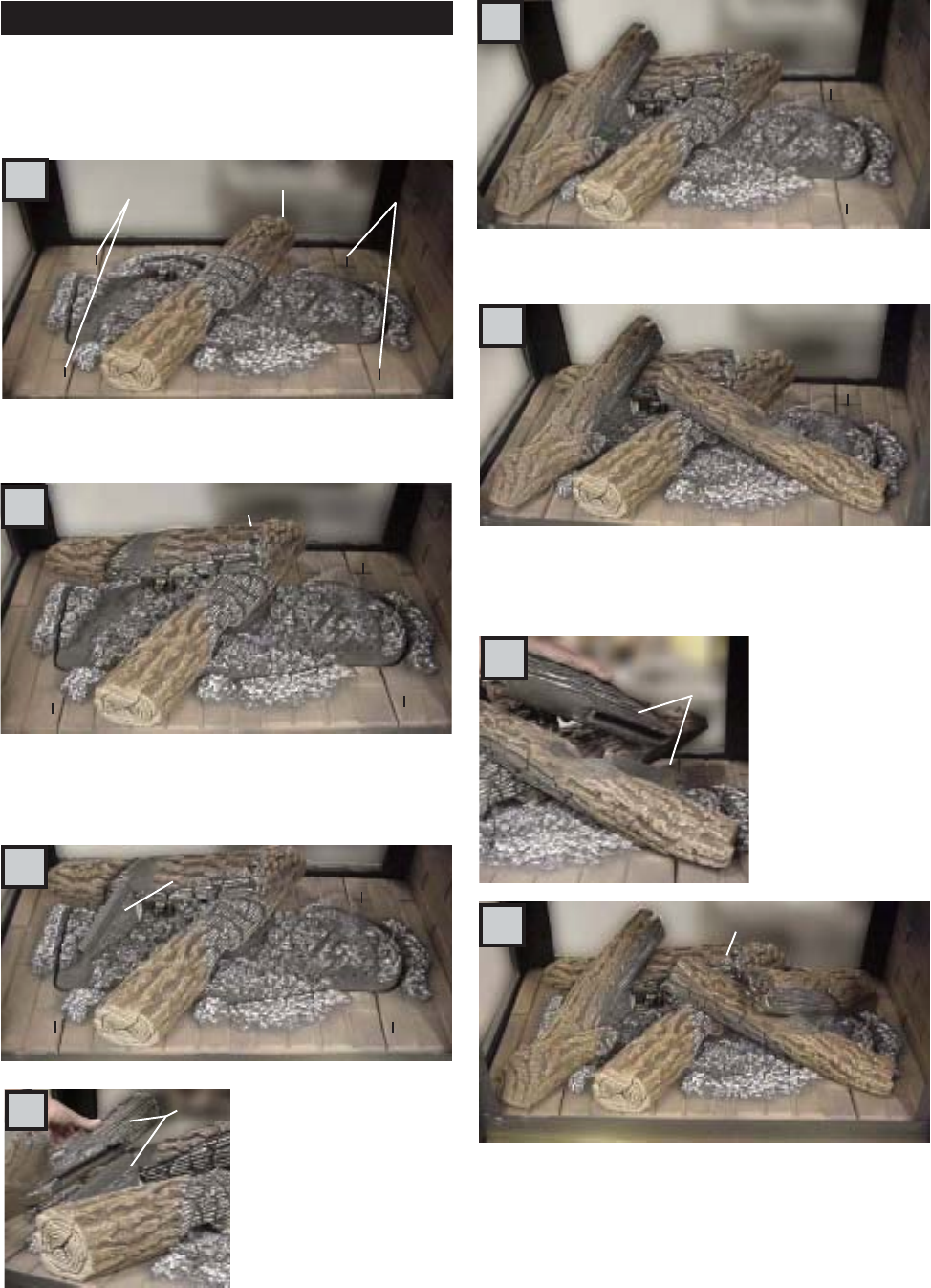
Combustible mantle clearance can vary according to the
mantle depth. Use the graph to help evaluate the clear-
ance needed. The three-sided top extension piece may be
removed if non-combustible framing is faced with a non-
combustible material. FIGURES 45 a-b
Dashed lines are suitable mantle sizes and clearances
when a non-combustible facing is used.
* SEE FIGURE 16.
P
I
P
I
3
1
2
L
O
T
N
O
L
O
T
H
I
L
O
F
F
O
FIGURE 42
FIGURE 44
TOP OF THE UNIT
TOP EXTENTION
7" MANTLE
3" MANTLE
*
8. Apply a heavy bead of waterproof caulking 2 inches above
the flashing. Slide the storm collar around the air terminal
and down to the caulking. Tighten to ensure that a weather-
tight seal between the air terminal and the collar is
achieved. Attach the other storm collar centered between
the air intake and air exhaust slots onto the air terminal.
Tighten securely. Attach the rain cap.
8. Continue adding rigid venting sections, sealing and
securing as above. Attach a 5" collapsed telescopic pipe
to the last section of rigid piping. Secure with screws and
seal. Repeat using a 8" telescopic pipe.
9. Run a bead of high temperature sealant around the
outside of the 5" elbow. Pull the adjustable pipe a mini-
mum 2" onto the elbow. Secure with 3 screws. Repeat with
the 8" telescopic pipe.
10. In the attic, slide the vent pipe collar down to cover up
the open end of the shield and tighten. This will prevent
any materials, such as insulation, from filling up the 1" air
space around the pipe.
It is best to frame your fireplace after it is positioned and
the vent system is installed. Use 2x4's and frame to local
building codes.
See PAGE 14 for bar type / countertop installation.
1. Move the fireplace into position and secure to the floor
using #10 hex head screws (not supplied).
2. Route a 3/8" N.P.T. black iron gas line, 1/2" type-L
copper tubing or equivalent to the fireplace.
3. For ease of accessibility, an optional remote wall
switch or millivolt thermostat may be installed in a conven-
ient location. Route 2-strand (solid core) millivolt wire
through the electrical hole located at the bottom left side of
the unit.
The recommended maximum lead length depends on
wire size:
WIRE SIZE MAX. LENGTH
14 gauge 100 feet
16 gauge 60 feet
18 gauge 40 feet
FIGURE 43
GAS INSTALLATION
FINISHING
MANTLE INSTALLATION
23
W415-0299 / C / 03.12.03
PHAZERTM logs, glowing and charcoal embers, exclusive
to Napoleon fireplaces, provide a unique and realistic glow-
ing effect that is different in every installation. Take the time
to carefully position the embers for a maximum glowing
effect. Figures 46 A - H.
1. Looking at the unit from the valve side, place log #1
diagonally across the textured burner cover onto the pins.
The texture is designed to cradle the underside of the log.
2. Depending on the type of installation, the view of the log
positioning will reverse. Here the lower end of log #2 rests
near the back left corner of the firebox on the locating pin.
The upper end sits on top of log #1, inside the groove on
log #2.
3. Log # 3 is made up of
two pieces, a and b. Piece
#3a is the base of log #3.
The base sits diagonally in
the designated area lo-
cated between logs #1 and
fits tight up against #2.
4. The slot in the under-
side of piece #3b fits over
#3a. Place the end of
piece #3b onto the pin.
5. When pieces #3a and #3b are attached to create log
#3, the upper end of log #3 should rest in the groove, on
top of log # 2.
6. As with log # 1, log #4 is also cradled by the texture of the
burner cover and the pin in the base. Position log #4 so that
the lower end fits onto the pin. The upper end rests against
the moulded locater on the top of log # 1.
7. Like log #3, log #5
also comes in two
pieces. The base
(#5a) slopes
outwards between
logs #2 and #4.
As with pieces #3a
& b, piece #5b fits
over piece #5a.
Place the end of
piece #5b onto the
pin.
8. The upper end of log #5 rests in the groove, on top of
log #4 and creates the final appearance of log set.
a
D
b
#3
#3
E
#5
a
b
G
ALOCATING PINS #1 LOCATING PINS
#2
B
C#3a
F
#4
#1
#2
#3 #4
#5
H
LOG PLACEMENT
24
W415-0299 / C / 03.12.03
FIGURE 50
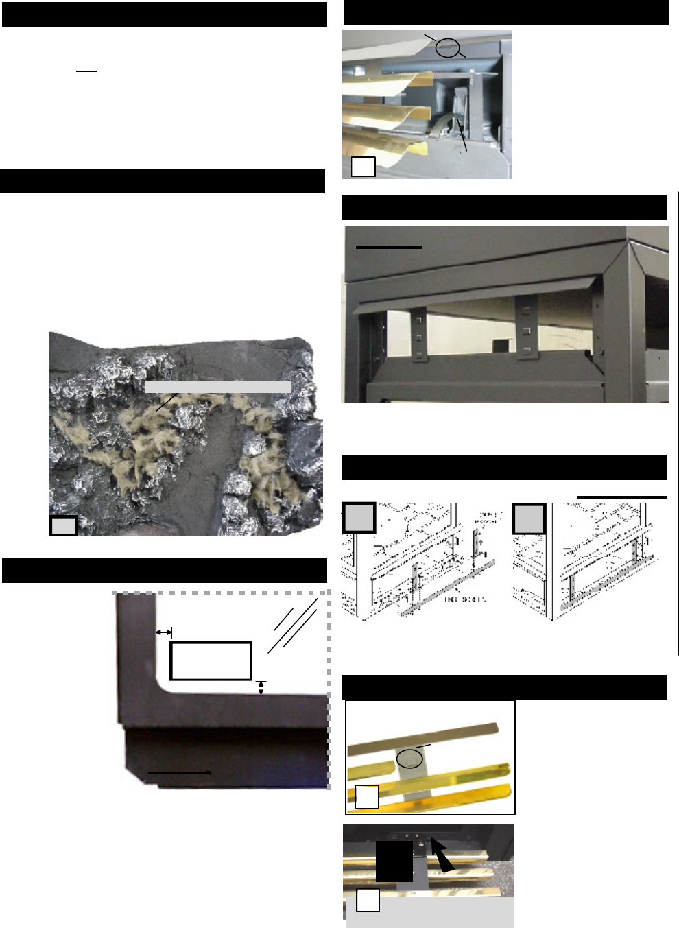
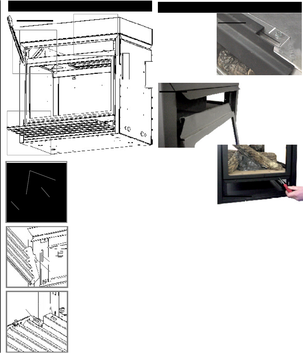
Attach the hood with louvre brackets by pressing the top
flange of the bracket into the clips along the top of the
louvre opening with louvre securing tabs facing out.
Using 6 screws, attach the lower louvre brackets and hinge
screen as illustrated. Be sure to install the louvre brack-
ets over the hinge screen.
FIGURES 51 a-b
AB
Tear the embers into small pieces and place on the ported
area of the burner. Care should be taken to shred the
embers into thin, small irregular pieces as only the ex-
posed edges of the fibre hairs will glow. The ember mate-
rial will only glow when exposed to direct flame; however,
care should be taken to not block the burner ports. Blocked
burner ports can cause an incorrect flame pattern, carbon
deposits and delayed ignition. PHAZERTM
logs glow when
exposed to direct flame.
Randomly place the embers around the bottom brick pan-
els in a realistic manner but not in contact with the flames.
Keep ember dust away from burner ports to avoid plugging
them.
Fine dust found in bottom of bag not to be used. PHAZERTM
logs, and embers glow when exposed to direct flame. Use
only certified PHAZERTM
logs, glowing embers and char-
coal embers available from your Napoleon / Wolf Steel Ltd.
dealer.
47
GLOWING EMBERS
DOOR OPENING AND
CLOSING: The upper lou-
vres must be removed to
allow the door to be
opened or closed. To ac-
cess the lower door latch,
open the valve control door.
Release the top and bot-
tom door latches, located
at the right side of the door.
TO INSTALL THE UP-
PER LOUVRES: Insert
the upper louvres into the
slots on both brackets.
Press the top flange of
the hood into the four
clips located along the
top of the unit as shown.
TO INSTALL THE LOWER
LOUVRE ASSEMBLY: At-
tach each hinge to the fire-
box with 2 screws.
Optional plated door trim, and arched door facia are avail-
able at your local Napoleon dealer.
LOUVRE
HOOD
SLOT
BRACKET
LOWER LOUVRES
(VALVE CONTROL DOOR)
52
53
GLOWING EMBERS
CHARCOAL EMBERS
DOOR INSTALLATION
UPPER LOUVRE BRACKETS & HOOD
LOWER LOUVRE BRACKETS & HINGE SCREEN
DOOR LATCH
HOOD
UPPER LOUVRE
49
FLANGE
CLIP
GVFL INSTALLATION
Remove the
backing of the
logo supplied and
place on the glass
viewing door, as
indicated. LOGO
½"
½"
LOGO PLACEMENT
FIGURE 48
25
W415-0299 / C / 03.12.03
Ensure that the
door is properly
clipped onto the
steel lip to pre-
vent overheat-
ing, glass break-
age and / or dis-
colouration of
the upper trim.
To install the door(s),
hook it over the steel lip
located above the door
opening.
Secure with screws
along the bottom of
the door. Tighten
screws snugly. Do not
over-tighten.
DOOR
STEEL LIP
FIGURE 55
FIGURE 56
END DOOR INSTALLATION
FIGURE 57
L36 LOUVRE INSTALLATION
FIGURE 54 a-c
HOOD
Attach the hood by pressing the
top flange into the clips along
the top of the louvre opening.
Secure using a screw through
the centre slot.
LOWER LOUVRES
Insert the hinge clips into the
slots located at the bottom left
and right corners of the unit.
To remove the louvres, pull the
back tabs of the clips forward,
while pushing the louvre assem-
bly back. Lift the clip.
UPPER LOUVRES
Insert the louvre tabs into the
slots located at the top left and
right corners of the unit.
ACLIPS
CENTRE
SLOT
FLANGE
SLOT
TAB
B
C
HINGE
CLIP SLOT
A
B
C
26
W415-0299 / C / 03.12.03
Remove the "Z" shaped
mounting bracket secured
to the burner, by the pilot.
Remove the thermodisc
from the bracket supplied in
the blower kit and attach to
the mounting bracket. Attach
the connectors from the
black and white wires to the
thermodisc.
Do not overtighten thermodisc or distort housing.
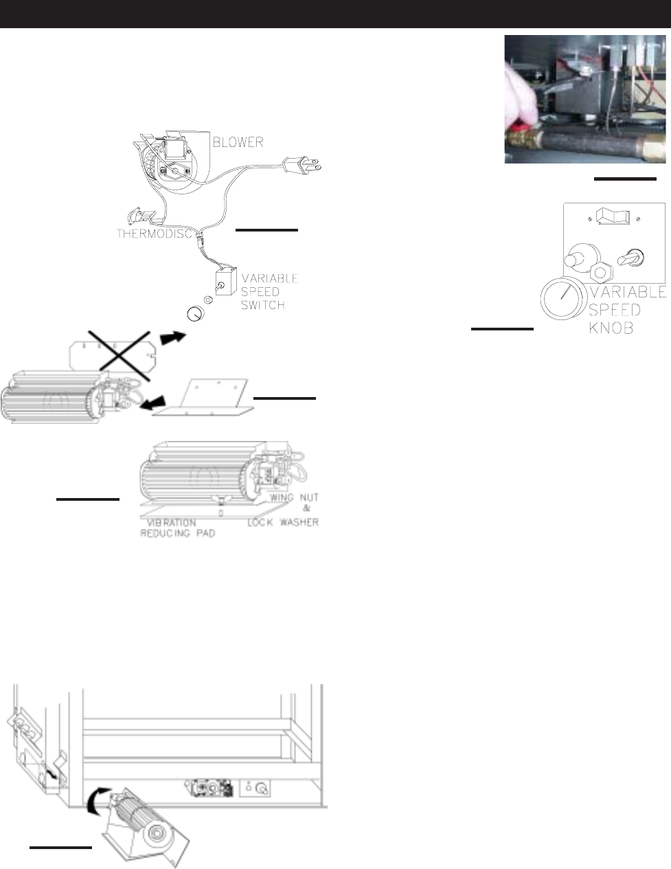
Attach the connectors from the
black and red wires to the
blower. Attach and secure the
variable speed switch using the
nut provided. Plug the harness
cord into the receptacle.
The wire harness provided in this kit is a universal har-
ness. When installed, ensure that any excess wire is
contained, preventing it from making contact with mov-
ing or hot objects.
Drywall dust will penetrate into the blower bearings,
causing irreparable damage. Care must be taken to
prevent drywall dust from coming into contact with the
blower or its compartment. Any damage resulting from
this condition is not covered by the warranty policy.
Because the blower is thermally activated, when turned
on, it will automatically start approximately 10 minutes
after lighting the fireplace and will run for approximately
30 - 45 minutes after the fireplace has been turned off.
Use of the fan increases the output of heat.
INSTALLATION TO BE DONE BY A QUALIFIED IN-
STALLER and must be electrically connected and grounded
in accordance with local codes. In the absence of local
codes, use the current CSA C22.1 CANADIAN ELECTRICAL CODE
in Canada or the ANSI/NFPA 70 NATIONAL ELECTRICAL CODE in the
United States.
Remove the
blower from its
mounting bracket
and attach to the
bracket supplied
with the fireplace.
This bracket is
found secured on
the mounting stud
located at the bot-
tom of the vent
side wall.
red
white
black
Position the vibration reducing pad, centred, onto the
threaded stud, piercing a hole into the pad. The blower
must be able to be positioned entirely onto the pad.
Tilt the blower onto its side and slide it past the controls.
Position the blower under the clip and onto the stud. Se-
cure with a wing nut.
FIGURE 61
FIGURE 58
FIGURE 60
FIGURE 62
FIGURE 63
FIGURE 59
The blower bracket contains two holes that allow the blower
to be positioned away from the intended gas supply hole.
OPTIONAL BLOWER INSTALLATION
27
W415-0299 / C / 03.12.03
• Turn off all gas to the fireplace.
• Open windows.
• Do not try to light any appliance.
• Do not touch any electric switch; do
not use any phone in your building.
• Immediately call your gas supplier from
a neighbour's phone. Follow the gas supplier's instruc-
tions.
• If you cannot reach your gas supplier, call the fire de-
partment.
L
ON/OFF
KNOB
F
F
O
P
I
N
O
L
O
T
I
H
PILOT
O
P
I
L
O
T
ADJUSTMENT
KNOB
FLAME
When lit for the first time, the fireplace will emit a slight
odour for a few hours. This is a normal temporary condi-
tion caused by the curing of the logs and the "burn-in" of
internal paints and lubricants used in the manufacturing
process and will not occur again. Simply open a window to
sufficiently ventilate the room.
After extended periods of non-operation such as following
a vacation or a warm weather season, the fireplace may
emit a slight odour for a few hours. This is caused by dust
particles in the heat exchanger burning off.
Purge the gas line with a glass door open. Assure that
a continuous gas flow is at the burner before re-install-
ing the door.
A. This fireplace is equipped with a pilot which must be lit
by hand while following these instructions exactly.
B. Before operating smell all around the fireplace area for
gas and next to the floor because some gas is heavier
than air and will settle on the floor.
C. Use only your hand to turn the gas control knob. Never
use tools. If the knob will not turn by hand, do not try to
repair it. Call a qualified service technician. Force or at-
tempted repair may result in a fire or explosion.
D. Do not use this fireplace if any part has been under
water. Immediately call a qualified service technician to
inspect the fireplace and replace any part of the control
system and any gas control which has been under water.
WARNING: The gas valve has an interlock device which
will not allow the pilot burner to be lit until the thermocou-
ple has cooled. Allow approximately 60 seconds for the
thermocouple to cool.
When lighting and re-lighting, the gas knob cannot be
turned from pilot to off unless the knob is depressed
slightly.
1. Stop! Read the above safety information on this label.
2. Turn off all electric power to the fireplace.
3. Turn the gas knob clockwise to off.
4. Wait five (5) minutes to clear out any gas. If you smell
gas including near the floor. Stop! Follow "B" in the
above safety information on this label. If you don't smell
gas go the next step.
5. Turn gas knob counter-clockwise to pilot.
6. Depress slightly and hold gas knob while lighting the
pilot with the push button ignitor. Keep knob depressed
for one minute, then release. If pilot does not continue
to burn, repeat steps 3 through 5.
7. With pilot lit, depress and turn gas knob counter-clock-
wise to on.
8. If equipped with remote on-off switch/thermostat, main
burner may not come on when you turn valve to on.
Remote switch must be in the on position to ignite
burner.
9. Turn on all electric power to the fireplace.
1. Turn off all electric power to the fireplace if service is to be
performed.
2. For a complete shut-down procedure: push in gas control
knob slightly and turn clockwise to off. Do not force.
3. For a temporary shut-down procedure: set thermostat to
lowest setting or remote switch to off. Press and turn the
gas knob clockwise to pilot.
Turn off the gas and electrical power before servicing the
fireplace.
CAUTION: Label all wires prior to disconnection when servic-
ing controls. Wiring errors can cause improper and dangerous
operation. Verify proper operation after servicing. This fireplace
and its venting system should be inspected before use and at
least annually by a qualified service person. The fireplace area
must be kept clear and free of combustible materials, gasoline
or other flammable vapours and liquids. The flow of combus-
tion and ventilation air must not be obstructed.
1. In order to properly clean the burner and pilot assembly,
remove the logs to expose both assemblies.
2. Keep the control compartment, logs, burner, air shutter open-
ing and the area surrounding the logs clean by vacuuming or
brushing, at least once a year.
3. Check to see that all burner ports are burning. Clean out any
of the ports which may not be burning or are not burning prop-
erly.
4. Check to see that the pilot flame is large enough to engulf
the thermocouple and thermopile and reaches toward the
burner with the third jet.
5. Replace the cleaned logs.
6. Check to see that the main and runner burners ignite com-
pletely on all openings when the gas knob for the burners is
turned on. A 5 to 10 second total light-up period is satisfactory. If
ignition takes longer, consult your Napoleon dealer / distributor.
7. Check that the gasketing on the sides, top and bottom of
the door is not broken or missing. Replace if necessary.
OPERATION / MAINTENANCE
FOR YOUR SAFETY READ BEFORE LIGHTING: WHAT TO DO IF YOU SMELL GAS:
LIGHTING INSTRUCTIONS
TO TURN OFF GAS
P
I
N
O
L
O
T
F
F
O
GAS KNOB
MAINTENANCE
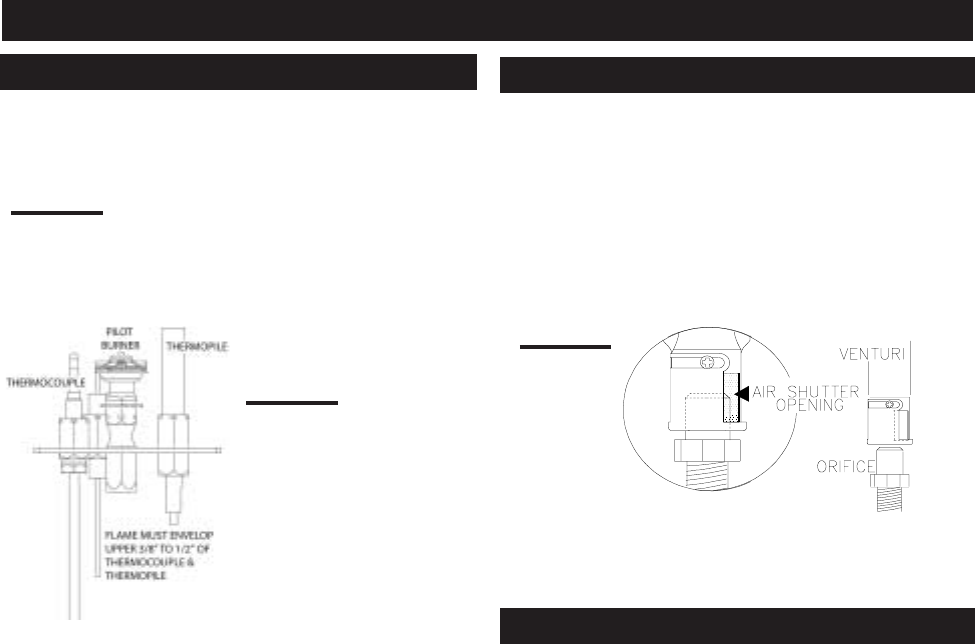
28
W415-0299 / C / 03.12.03
Adjust the pilot screw to provide properly sized flame. Turn
in a clockwise direction to reduce the gas flow.
Natural gas models have air shutters set at 1/4 (.250") inch
open. Propane gas models have air shutters set at 7/16
(.437) inch open. Closing the air shutter will cause a more
yellow flame, but can lead to carboning. Opening the air
shutter will cause a more blue flame, but can cause flame
lifting from the burner ports. The flame may not appear
yellow immediately; allow 15 to 30 minutes for the final
flame colour to be established.
FIGURE 66
FIGURE 64
FIGURE 65
AIR SHUTTER ADJUSTMENT MUST ONLY BE DONE BY A
QUALIFIED GAS INSTALLER!
WARNING: This is a fast act-
ing thermocouple. It is an in-
tegral safety component.
Replace only with a fast act-
ing thermocouple supplied
by Wolf Steel Ltd.
Vertical installations may display a very active flame.If this
appearance is not desirable,the vent exit must be restricted
using the optional restrictor vent kit, RP40-KT. This will
reduce
the velocity of the exhaust gases,slowing down the flame
pattern and creating a more traditional gentle appearance.
Specific instructions are included with the kit.
ADJUSTMENTS
PILOT BURNER ADJUSTMENT VENTURI ADJUSTMENT
RESTRICTING VERTICAL VENTS

29
W415-0299 / C / 03.12.03
# PART No. DESCRIPTION
1* W361-0016 GLOWING EMBERS
2* W550-0001 CHARCOAL EMBERS
3 W562-0009 DOOR GASKET (100 INCHES)
4 W010-0454 GLASS W/ GASKET
5* W500-0028 FIRESTOP - FLEXIBLE VENTING
6* W385-0245 NAPOLEON LOGO
7* W573-0008 HIGH TEMP SEALANT
8 GL-634 BGD40 LOGSET
9 W135-0153 LOG#1
10 W135-0154 LOG#2
11 W135-0155 LOG#3 - PIECE A
12 W135-0156 LOG#3 - PIECE B
13 W135-0157 LOG#4
14 W135-0158 LOG#5 - PIECE A
15 W135-0159 LOG#5 - PIECE B
16 W475-0265 END FIBRE BRICK PANEL - FOR WALL
17 W475-0259 END FIBRE BRICK PANEL - FOR BURNER
18 W475-0260 END FIBRE BRICK PANEL - FOR BURNER
19 W475-0261 SIDE FIBRE BRICK PANEL - FOR BURNER
20 W475-0262 SIDE FIBRE BRICK PANEL - FOR BURNER
21 W080-0519 BOTTOM LOUVRE BRACKET
22 W500-0193 BRICK PANEL RETAINER
23 N010-0279 SIDE LOUVRE HOOD W/ LOUVRE BRACKETS
24 W200-0114 SIDE DOOR COVER
25 N010-0327 SIDE DOOR HEAT SHIELD
26 W300-0057 END DOOR TEMPERED GLASS ONLY
27 W010-0873 END DOOR TEMPERED GLASS C/W GASKET
3 W562-0009 DOOR GASKET (100 INCHES)
28 W475-0263 SIDE BRICK PANEL - FOR WALL
29 N010-0310 END LOUVRE HOOD W/ LOUVRE BRACKETS
30 W500-0192 END BRICK PANEL RETAINER
3 W562-0009 DOOR GASKET (100 INCHES)
16 W475-0265 END FIBRE BRICK PANEL - FOR WALL
31 N010-0326 END DOOR HEAT SHIELD
32 W200-0117 END DOOR COVER
30 W500-0192 END BRICK PANEL RETAINER
33 W010-0516 BLACK SIDE DOOR c/w GLASS
28 W010-0873 END DOOR TEMPERED GLASS
C/W GASKET
33 W010-0516 BLACK SIDE DOOR c/w GLASS
30 N010-0310 END LOUVRE HOOD W/ LOUVRE BRACKETS
34 W010-0871 REPLACEMENT BURNER
35 W010-0801 NATURAL GAS PILOT ASSEMBLY
35 W010-0800 PROPANE GAS PILOT ASSEMBLY
36 W455-0069 NATURAL GAS PILOT INJECTOR
36 W455-0067 PROPANE GAS PILOT INJECTOR
37* W660-0005 BURNER ON/OFF SWITCH
38 W680-0004 THERMOPILE
39 W680-0005 THERMOCOUPLE
40 W240-0006 ELECTRODE W/ WIRE
41 W357-0001 PIEZO IGNITER
42 N455-0003 MAIN BURNER ORIFICE - PROPANE
42 W455-0072 MAIN BURNER ORIFICE - NATURAL GAS
43 W725-0026 PROPANE GAS VALVE
43 W725-0025 NATURAL GAS VALVE
GD420 (5 FOOT)
44* W010-0772 5" FLEXIBLE ALUMINIUM LINER - (5 FT.) C/W SPACERS
45* W730-0012 8" FLEXIBLE ALUMINIUM LINER - (5FT.)
GD430 (10 FOOT)
46* W730-0013 8" FLEXIBLE ALUMINIUM LINER -(10FT.)
47* W010-0773 5" FLEXIBLE ALUMINIUM LINER-(10 FT.) C/W SPACERS
48* W010-0810 WALL SUPPORT ASSEMBLY
49* 1/12 TO 7/12 PITCH - GD410
50* 8/12 TO 12/12 PITCH - GD411
51* FLAT ROOF - GD412
52* W120-0036 VERTICAL CAP
53* W170-0063 STORM COLLAR
54* W010-0453 ROOF SUPPORT
55* W263-0054 /W263-0055 / W263-00056 ROOF FLASHING
56* PERISCOPE - GD401
57* WALL TERMINAL KIT - GD422
REPLACEMENTS
Contact your dealer or the factory for questions concerning
prices and policies on replacement parts. Normally all parts
can be ordered through your Napoleon dealer or distribu-
tor.
When ordering replacement parts always give the follow-
ing information:
1. MODEL & SERIAL NUMBER OF FIREPLACE
2. INSTALLATION DATE OF FIREPLACE
3. PART NUMBER
4. DESCRIPTION OF PART
5. FINISH
6. TOP OR REAR VENT
* WARNING: This is a fast acting thermocouple. It is an
integral safety component. Replace only with a fast
acting thermocouple supplied by Wolf Steel Ltd.
COMPONENTS COMMON TO ALL UNITS BURNER COMPONENTS
COMPONENTS UNIQUE TO OPEN END UNIT
COMPONENTS UNIQUE TO SEE-THRU UNIT
COMPONENTS UNIQUE TO PENINSULA UNIT
ROOF TERMINAL KITS
TERMINAL KITS
VENT KITS
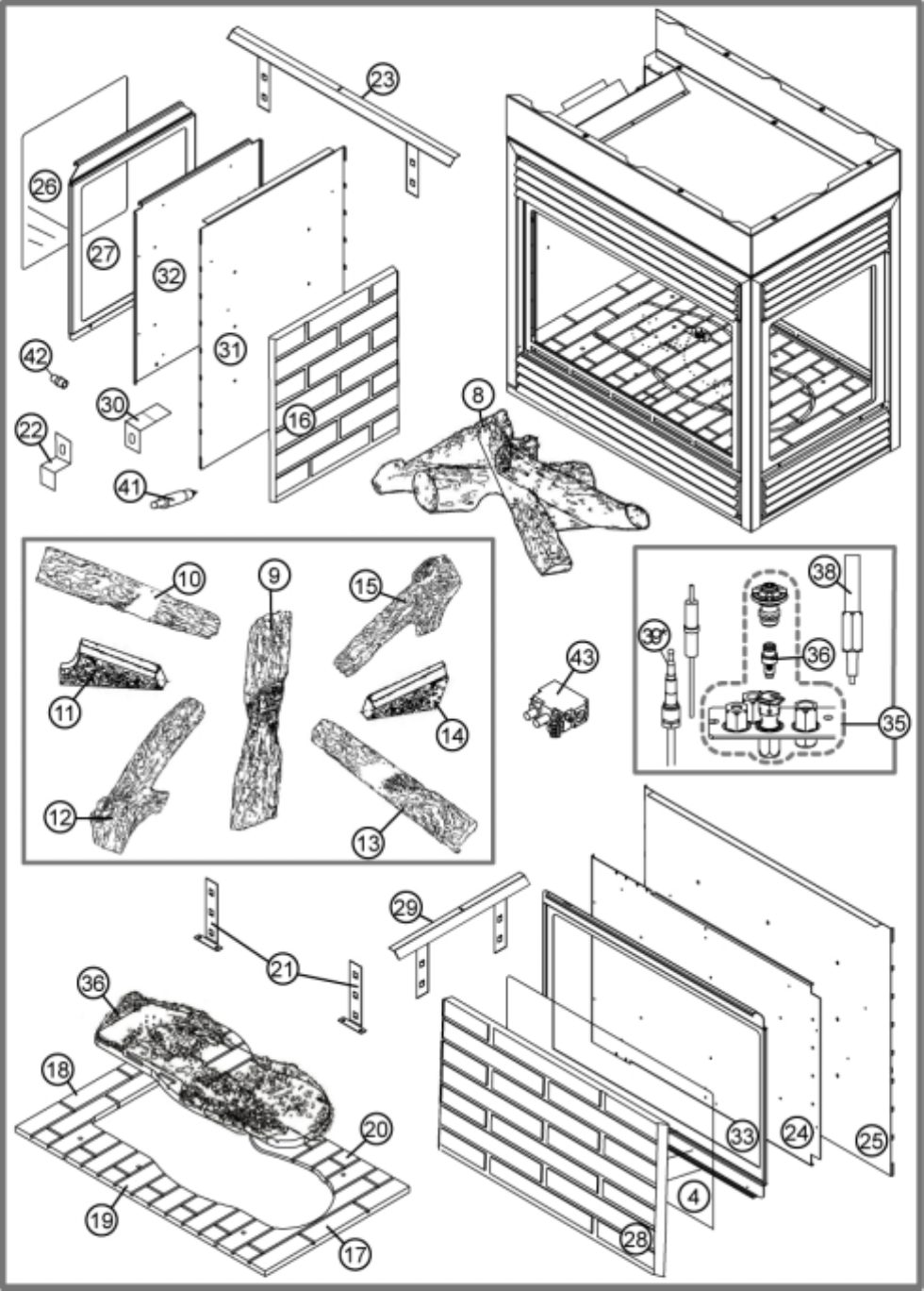
30
W415-0299 / C / 03.12.03
* WARNING: This is a fast acting thermocouple. It is an integral safety component.
Replace only with a fast acting thermocouple supplied by Wolf Steel Ltd.
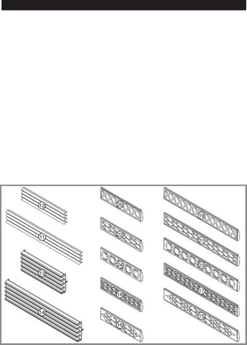
31
W415-0299 / C / 03.12.03
# PART No. DESCRIPTION
1 W690-0001 MILLIVOLT THERMOSTAT
2 GD501 HEAT GUARD
3* W573-0008 HI-TEMP SEALANT
4* W010-0370 WALL SUPPORT ASSEMBLY
5 GZ-550-1KT BLOWER KIT
6* W175-0170 DURA-VENT ZERO CLEARANCE ADAPTOR
7* W500-0033 VARIABLE SPEED SWITCH WALL MOUNTING PLATE
8* W660-0010 REMOTE CONTROL - ADVANTAGE
8* W660-0011 REMOTE CONTROL - ADVANTAGE PLUS
9* W660-0013 MODULATING REMOTE - CONTROLS FLAME & BLOWER
10* W175-0166 5" COUPLER
10* W175-0002 8" COUPLER
11 GVFLK LOUVRE KIT - BLACK
11 GVFLPB LOUVRE KIT - POLISHED BRASS
11 GVFLAB LOUVRE KIT - ANTIQUE BRASS
11 GVFLSS LOUVRE KIT - STAINLESS STEEL
12* BGDELK END LOUVRE KIT - BLACK
12* BGDELPB END LOUVRE KIT - POLISHED BRASS
12* BGDELAB END LOUVRE KIT - ANTIQUE BRASS
12* BGDELSS END LOUVRE KIT - STAINLESS STEEL
13 L36K LOUVRE KIT - UPPER & LOWER - BLACK
13 L36AB LOUVRE KIT - UPPER & LOWER - ANTIQUE BRASS
13 L36PB LOUVRE KIT - UPPER & LOWER - POLISHED BRASS
13 L36SS LOUVRE KIT - UPPER & LOWER - BRUSHED STAINLESS STEEL
14* ELB40K END LOUVRE KIT - BLACK
14* ELB40PB END LOUVRE KIT - POLISHED BRASS
14* ELB40AB END LOUVRE KIT - ANTIQUE BRASS
14* ELB40SS END LOUVRE KIT - STAINLESS STEEL
15 HOIG-1 HERITAGE ORNAMENTAL INSET-GOLD PLATED
15 HOIKG-1 HERITAGE ORNAMENTAL INSET-BLACK GOLD PLATED
15 HOIBC-1 HERITAGE ORNAMENTAL INSET-BRUSHED COPPER PLATED
15 HOIBG -1 HERITAGE ORNAMENTAL INSET-BRUSHED GOLD PLATED
16* EHOIG -1 END HERITAGE ORNAMENTAL INSET-GOLD PLATED
16* EHOIKG-1 END HERITAGE ORNAMENTAL INSET-BLACK GOLD PLATED
16* EHOIBC-1 END HERITAGE ORNAMENTAL INSET
-BRUSHED COPPER PLATED
16* EHOIBG -1 END HERITAGE ORNAMENTAL INSET - BRUSHED GOLD PLATED
17 DOIG-1 DIAMOND ORNAMENTAL INSET - GOLD PLATED
17 DOIKG-1 DIAMOND ORNAMENTAL INSET - BLACK GOLD PLATED
17 DOIBC-1 DIAMOND ORNAMENTAL INSET - BRUSHED COPPER PLATED
17 DOIBG-1 DIAMOND ORNAMENTAL INSET - BRUSHED GOLD PLATED
18* EDOIG-1 END DIAMOND ORNAMENTAL INSET - GOLD PLATED
18* EDOIKG-1 END DIAMOND ORNAMENTAL INSET - BLACK GOLD PLATED
18* EDOIBC-1 END DIAMOND ORNAMENTAL INSET - BRUSHED COPPER PLATED
18* EDOIBG-1 END DIAMOND ORNAMENTAL INSET - BRUSHED GOLD PLATED
19 GOIG-1 GOTHIC ORNAMENTAL INSET - GOLD PLATED
19 GOIKG-1 GOTHIC ORNAMENTAL INSET - BLACK GOLD PLATED
19 GOIBC-1 GOTHIC ORNAMENTAL INSET - BRUSHED COPPER PLATED
19 GOIBG-1 GOTHIC ORNAMENTAL INSET - BRUSHED GOLD PLATED
20* EGOIG-1 END GOTHIC ORNAMENTAL INSET - GOLD PLATED
20* EGOIKG-1 END GOTHIC ORNAMENTAL INSET - BLACK GOLD PLATED
20* EGOIBC-1 END GOTHIC ORNAMENTAL INSET - BRUSHED COPPER PLATED
20* EGOIBG-1 END GOTHIC ORNAMENTAL INSET - BRUSHED GOLD PLATED
21 SOIG-1 SEASHELL ORNAMENTAL INSET - GOLD PLATED
21 SOIKG-1 SEASHELL ORNAMENTAL INSET - BLACK GOLD PLATED
21 SOIBC-1 SEASHEL ORNAMENTAL INSET - BRUSHED COPPER PLATED
21 SOIBG-1 SEASHELL ORNAMENTAL INSET - BRUSHED GOLD PLATED
22* ESOIG-1 END SEASHELL ORNAMENTAL INSET - GOLD PLATED
22* ESOIKG-1 END SEASHELL ORNAMENTAL INSET - BLACK GOLD PLATED
22* ESOIBC-1 END SEASHEL ORNAMENTAL INSET - BRUSHED COPPER PLATED
22* ESOIBG-1 END SEASHELL ORNAMENTAL INSET - BRUSHED GOLD PLATED
23 EOIG-1 ECLIPSE ORNAMENTAL INSET - GOLD PLATED
23 EOIKG-1 ECLIPSE ORNAMENTAL INSET - BLACK GOLD PLATED
23 EOIBC-1 ECLIPSE ORNAMENTAL INSET - BRUSHED COPPER PLATED
23 EOIBG-1 ECLIPSE ORNAMENTAL INSET - BRUSHED GOLD PLATED
24* EEOIG-1 END ECLIPSE ORNAMENTAL INSET - GOLD PLATED
24* EEOIKG-1 END ECLIPSE ORNAMENTAL INSET - BLACK GOLD PLATED
24* EEOIBC-1 END ECLIPSE ORNAMENTAL INSET - BRUSHED COPPER PLATED
24* EEOIBG-1 END ECLIPSE ORNAMENTAL INSET - BRUSHED GOLD PLATED
32* GD825N VALVE REGULATOR FOR W660-0013 - NATURAL GAS
33* GD825P VALVE REGULATOR FOR W660-0013 - PROPANE
41* RP40-KT RESTRICTOR VENT KIT
42* W175-0205 CONVERSION KIT - NG - LP
42* W175-0206 CONVERSION KIT - LP - NG
ACCESSORIES
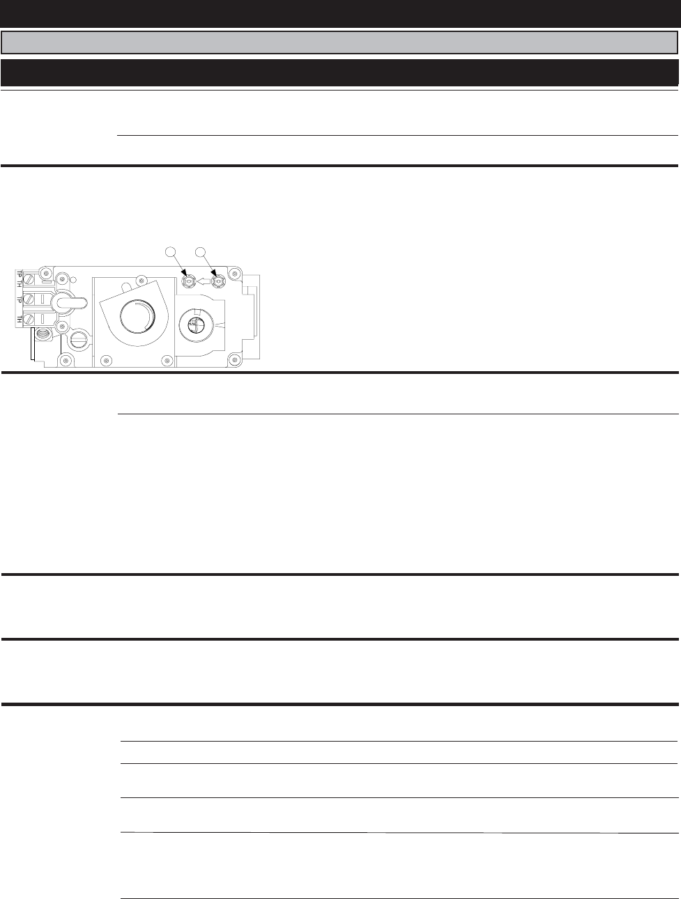
32
W415-0299 / C / 03.12.03
Carbon is being
deposited on
glass, logs or
combustion
chamber sur-
faces.
Flame is impinging on the
logs or combustion cham-
ber.
- check that the logs are correctly positioned.
- open air shutter to increase the primary air.
- check the input rate: check the manifold pressure and orifice size
as specified by the rating plate values.
- check that the door gasketing is not broken or missing and that the
seal is tight.
- check that both 5" and 8" vent liners are free of holes and well
sealed at all joints.
- check that minimum rise per foor has been adhered to for any
horizontal venting.
Air shutter has become
blocked
- ensure air shutter opening is free of lint or other obstructions.
Flames are con-
sistently too large
or too small.
Carboning occurs.
- check pressure readings:
Inlet pressure can be checked by turning screw (A) counter-clock-
wise 2 or 3 turns and then placing pressure gauge tubing over the
test point. Gauge should read 8" (minimum 4.5") water column for
natural gas or 13" (11" minimum) water column for propane. Check
that main burner is operating on "HI".
Outlet pressure can be checked the same as above using screw (B).
Gauge should read 3.5" water column for natural gas or 10" water
column for propane. Check that main burner is operating on "HI".
AFTER TAKING PRESSURE READINGS, BE SURE TO TURN
SCREWS CLOCKWISE FIRMLY TO RESEAL. DO NOT
OVERTORQUE.
Leak test with a soap and water solution.
Unit is over-fired or under-
fired.
P
I
A
B
P
I
L
O
T
N
O
L
O
T
H
I
L
O
F
F
O
Main burner flame
is a blue, lazy,
transparent
flame.
Blockage in vent. - remove blockage. In really cold conditions, ice buildup may occur
on the terminal and should be removed as required.
Incorrect installation. - refer to Figure 34 to ensure correct location of storm collars.
White / grey film
forms.
Sulphur from fuel is being
deposited on glass, logs or
combustion chamber sur-
faces.
- clean the glass with a recommended gas fireplace glass cleaner.
Do not clean glass when hot!
If deposits are not cleaned off regularly, the glass may become per-
manently marked.
Exhaust fumes
smelled in room,
headaches.
Fireplace is spilling. - check door seal and relief flap seal.
- check for chimney blockage
- check that chimney is installed to building code.
- room is in negative pressure; increase fresh air supply.
Pilot goes out
when the gas knob
is released.
The gas valve has
an interlock de-
vice which will not
allow the pilot
burner to be lit
until the thermo-
couple has
cooled. Allow ap-
proximately 60
seconds for the
thermocouple to
cool.
System is not correctly
purged.
- purge the gas line with a glass door open.
Out of propane gas. - fill the tank.
Pilot flame is not large
enough
- turn up the pilot flame.
- gently twist the pilot head to improve the flame pattern around the
thermocouple.
Pilot flame is not engulfing
the thermocouple.
Thermocouple shorting /
faulty.
- loosen and tighten thermocouple.
- clean thermocouple and valve connection.
- replace thermocouple.
- replace valve.
Faulty valve. - replace.
(vertical vent)
TROUBLE SHOOTING GUIDE
B
EFORE
ATTEMPTING
TO
TROUBLESHOOT
,
PURGE
YOUR
UNIT
AND
INITIALLY
LIGHT
THE
PILOT
AND
THE
MAIN
BURNER
WITH
THE
GLASS
DOOR
OPEN
.
SYMPTOM PROBLEM TEST SOLUTION
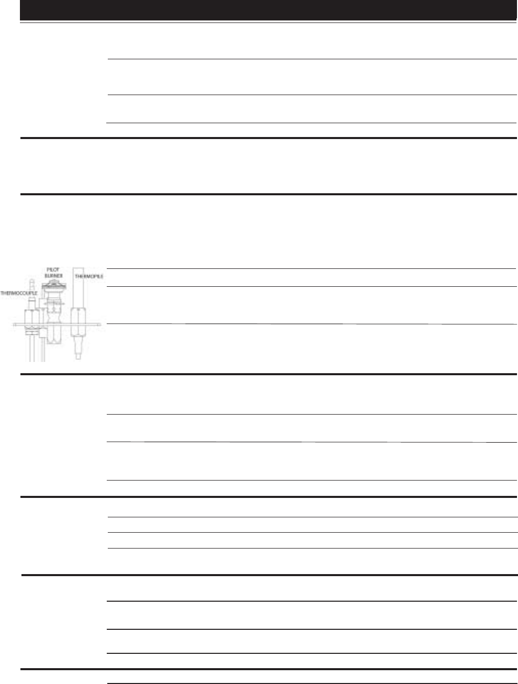
33
W415-0299 / C / 03.12.03
Main burner goes
out; pilot goes out.
Refer to "
MAIN BURNER GOES OUT; PILOT STAYS ON
"
Vent is blocked - check for vent blockage.
- check joint seals and installation.
5" flexible vent has become
disconnected from fireplace.
- re-attach to fireplace.
Vent is re-circulating
Pilot burning; no
gas to main
burner; gas knob
is on 'HI'; wall
switch / thermo-
stat is on.
Themostat or switch is de-
fective.
- connect a jumper wire across the wall switch terminals; if main
burner lights, replace switch / thermostat.
Wall switch wiring is defec-
tive.
- disconnect the switch wires from the valve & connect a jumper wire
across terminals 1 & 3; if the main burner lights, check the wires for
defects and / or replace wires.
Main burner orifice is
plugged.
- remove stoppage in orifice.
- replace.
Faulty valve.
Pilot goes out
while standing;
Main burner is in
'OFF' position.
Gas piping is undersized. - turn on all gas appliances and see if pilot flame flutters, dimin-
ishes or extinguishes, especially when main burner ignites. Monitor
appliance supply working pressure.
- check if supply piping size is to code. Correct all undersized piping.
Pilot will not light. - check if pilot can be lit by a match
- check that the wire is connected to the push button ignitor.
- check if the push button ignitor needs tightening.
- replace the wire if the wire insulation is broken or frayed.
- replace the electrode if the ceramic insulator is cracked or broken.
- replace the push button ignitor.
No spark at pilot burner
- fill the tank.Out of propane gas
Spark gap is incorrect - spark gap should be 0.150" to 0.175" (5/32" to 11/65" approx.) from
the electrode tip and the pilot burner. To ensure proper electrode
location, tighten securing nut (finger tight plus 1/4 turn).
No gas at the pilot burner - check that the manual valve is turned on.
- check the pilot orifice for blockage.
- replace the valve.
- call the gas distributor.
Main burner goes
out; pilot stays on.
Pilot flame is not large
enough or not engulfing the
thermopile
- turn up pilot flame.
- replace pilot assembly.
Thermopile shorting - clean thermopile connection to the valve. Reconnect.
- replace thermopile / valve.
Remote wall switch wire is
too long; too much resist-
ance in the system.
- shorten wire to correct length or wire gauge.
Faulty thermostat or switch. - replace.
Remote wall
switch is in "OFF"
position; main
burner comes on
when gas knob is
turned to "ON" po-
sition.
Flames are very
aggressive.
Wall switch is mounted up-
side down
- reverse.
Faulty valve.
Door is ajar
Venting action is too great.
- replace.
- replace.Remote wall switch is
grounding.
- check for ground (short); repair ground or replace wire.Remote wall switch wire is
grounding.
-tighten door clamps
-restrict vent exit with restrictor vent kit, RP40-KT.
SYMPTOM PROBLEM TEST SOLUTION

34
W415-0299 / C / 03.12.03
Wolf Steel Fireplace Service History
This fireplace must be serviced annually depending on usage.
Date Service Technician
Name Service Performed Special ConcernsDealer Name

35
W415-0299 / C / 03.12.03
NOTES

36
W415-0299 / C / 03.12.03
NOTES
