Narco Avionics AT155 Aviation Transponder User Manual installation manaul
Narco Avionics Inc Aviation Transponder installation manaul
installation manaul
PRINTED IN U.S.A. REV 1.0 MAY, 2002
Narco Avionics
AT155 TSO
Transponder
Installation Manual
03608-0620
Narco Avionics Inc.
270 Commerce Drive
Ft. Washington, Pa. 19034
U.S.A.
REV 1.0
NOTICE
While every effort has been made by Narco Avionics Inc.
to ensure accuracy in the preparation of this Installation Manual,
Narco assumes no responsibility for errors or omissions
Narco Avionics can be reached by calling :
Phone : 215-643-2900
FAX : 215-643-0197
Or on the Internet at www.narcoavionics.com

May, 2002 REV 1.0 i
Narco Avionics AT155 TSO
TABLE OF CONTENTS
SECTION
NUMBER TITLE PAGE
NUMBER
1.1 GENERAL 1-1
1.1.1 Manual Organization 1-1
1.2 PRODUCT DESCRIPTION 1-1
1.3 PRODUCT SPECIFICATIONS 1-2
1.4 TSO EXPLANATION 1-3
1.4.1 AT155 Antenna 1-3
1.5 UNITS AND ACCESSORIES SUPPLIED 1-3
1.6 OPTIONAL ACCESSORIES 1-4
1.7 MISCELLANEOUS ITEMS REQUIRED BUT NOT SUPPLIED. 1-4
1.8 OPERATOR LICENSE REQUIIREMENTS 1-4
1.9 OPERATION 1-5
1.9.1 Function Selector Switch 1-5
1.9.2 IDENT/DIM 1-6
1.9.3 Code Selector 1-6
2.1 INTRODUCTION 2-1
2.2 PRELIMINARY INSPECTION 2-1
2.2.1 Unpacking 2-1
2.2.2 Electrical Bench Test. 2-2
2.2.2.1 Test Equipment Required. 2-2
2.2.2.2 Test Procedure 2-2
2.3 MECHANICAL INSTALLATION. 2-5
2.3.1 Mounting Tray 2-5
2.3.2 Insertion And Removal Of The AT155 2-5
2.4 ANTENNA INSTALLATION 2-7
2.4.1 Antenna Location And Mounting. 2-7
2.4.2 Antenna Extension Cable. 2-8
2.5 ELECTRICAL INSTALLATION 2-9
2.5.1 Power And Interconnect Cable 2-9
2.5.2 Cable Fabrication 2-11
2.5.3 Pilot Lamps 2-12
2.5.4 External Suppression 2-12
2.5.5 Remote IDENT 2-13
2.5.6 Altitude Digitizer 2-13
2.6 POST INSTALLATION TESTS 2-13
2.6.1 Preflight Tests 2-13
2.6.2 Flight Test 2-14
2.7 AIRCRAFT LICENSE REQUIREMENTS. 2-14
APPENDIX A – CERTIFICATION DOCUMENTS
A.1 ENVIRONMENTAL QUALIFICATION FORM A-1
A.2 CONTINUED AIRWORTHINESS A-2
R.1 MANUAL REVISION HISTORY R-1

ii REV 1.0 May, 2002
LIST OF ILLUSTRATIONS
FIGURE
NUMBER TITLE PAGE
NUMBER
1-1 AT155 TSO FRONT PANEL 1-7
2-1 BENCH TEST SET-UP 2-2
2-2 INSTALLATION DIAGRAM 2-6
2-3 AT155 ANTENNA MOUNTING 2-7
2-4 POWER AND INTERCONNECT CABLE 2-9
2-5 ORIENTATION DIAGRAM 2-10
2-6 CRIMPING TOOL 2-11
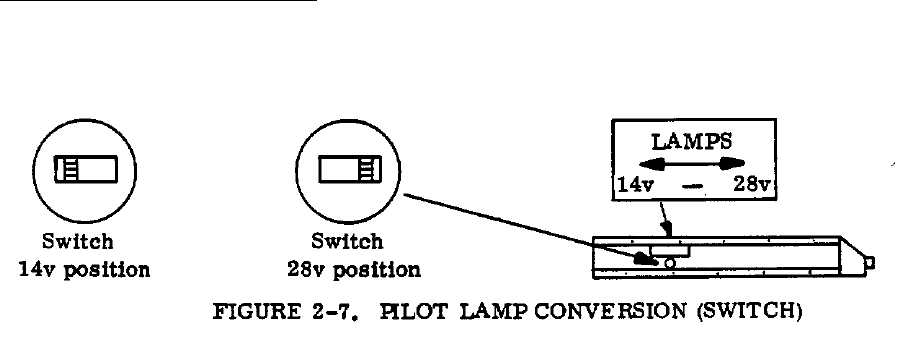
2-7 PILOT LAMP CONVERSION (SWITCH) 2-12
LIST OF TABLES
TABLE
NUMBER TITLE PAGE
NUMBER
1.1 UNITS AVAILABLE 1-3
1.2 INSTALLATION KIT (3604-0500) 1-4
2.1 ALTITUDE DIGITIZER INPUTS 2-4
INTRODUCTION
SECTION 1
May, 2002 REV 1.0 1-1
1.1 GENERAL
In support of the Narco Avionics AT155 TSO Transponder, this manual provides detailed installation and
operation procedures.
"This manual is intended for use only by persons qualified to service equipment
in this manual pursuant to current regulatory requirements."
1.1.1 Manual Organization
Organized into two major sections the manual includes the following:
Section 1, Introduction - general information required in planning the installation
Section 2, Installation - detailed procedures for performing the mechanical and electrical installation
1.2 PRODUCT DESCRIPTION
The AT155 TSO consists of a receiver tuned to the frequency of a ground interrogation station (1030 MHz),
logic circuitry to check the validity of the received interrogation and encode a reply containing pertinent
identification information, and a transmitter which sends the coded reply to the ground station. When an
optional altitude digitizer, Narco Model AR-850, is incorporated, coded altitude information will be transmitted
to the ground station.
The AT155 has been designed for 14V or 28V operation. If the AT155 is replacing an existing AT50A or
AT150 that uses an MP10 or a passive voltage converter these do not have to be removed.
Narco Avionics AT155
1-2 REV 1.0 May, 2002
1.3 PRODUCT SPECIFICATIONS
Mechanical
Physical Dimensions and Mounting Refer to appropriate diagram in Section 2
Weight 1.5lbs. (0.68kg)
Electrical
Power Requirements 13.75 VDC 27.5VDC
Standby 210mA 125mA
Transmit 1.2 A 530mA
Pilot Lamps 220mA 90mA
Receiver
Frequency 1030 MHz
Frequency Stability Crystal Controlled
Sensitivity Minimum trigger level (MTL) -69 to -74 dBm
Side-Lobe Suppression (SLS) 99% or greater for signals from 3 dB to 50 dB above MTL
Dynamic Range Logarithmic pulse response 50 dB or greater above MTL
Bandwidth -60dB at ± 25 MHz
Decoding Capability
Mode A Pulse pair spaced at 8 ±0.5µs
Mode C Pulse pair spaced at 21 ±0.5µs
Side-Lobe Suppression 35 µs suppression upon receipt of two pulses spaced 2 ±0.5µs
apart.
Encoding Capability
Mode A 4096 reply codes selectable by front panel switches.
Mode C Altitude reporting to 30,700 feet
SPIP (Special Position An SPIP may be added to mode A for 20 ±5 seconds
Identification Pulse)
Transmitter
Frequency 1090 MHz
Pulse Power 250 watts nominal, 190 watts minimum
External Interference Suppression (positive)
Pulse Amplitude 5 to 50 volts
Load on Suppressor 3300 ohms
External Interference Suppression (negative)
Voltage 0.8V (maximum)
Current 5 mA

INTRODUCTION
SECTION 1
May, 2002 REV 1.0 1-3
1.4 TSO EXPLANATION
The TSO'd AT155 is designed to be instrument panel mounted within the cabin environment of fixed and rotary
wing aircraft using piston or turbine single or multi-engines. It will operate and has been tested up to 30,000
feet for installations in non-pressurized as well as pressurized aircraft. This equipment requires direct current
power but is designed to be installed in aircraft that have additional on board alternating current sources.
Environmental testing was done to RTCA Document DO-160C. The Environmental categories are listed in
Appendix A of this document.
1.4.1 AT155 Antenna
The AT155 Antenna meets the requirements of TSO-C74b Class 1, Environmental
Category /JA/JAAAXXXXXX.
1.5 UNITS AND ACCESSORIES SUPPLIED
The following two tables may be used to: 1) check the contents of your order and, 2) to order additional Units or
components.
TABLE 1.1 UNITS AVAILABLE
Unit Part Number Unit and Description Subassembly Part Number
03608-0300 AT155 TRANSPONDER ASSY,
Complete with:
AT155 Transponder,
Tray Assy
Antenna Assy
Installation Kit
01545-0101
56282-0102
71233-0101
03604-0500

Narco Avionics AT155
1-4 REV 1.0 May, 2002
TABLE 1.2. INSTALLATION KIT (03604-0500)
Item Part Number Description Qty
1
2
3
4
5
6
7
8
9
10
81213-0034
41316-0009
41317-0001
82802-0005
82900-0008
82969-0004
82814-0004
82815-0405
41152-0005
99090-0001
SPACER
CONNECTOR, 18 pin (Molex)
CONTACT, Crimp type
WASHER, Lock, Int. Tooth, #6
NUT, Hex, 6-32
WASHER, Lock, Split, #4
SCREW, Bind Hd, 4-40 x 5/16
SCREW, Bind Hd, 6-32 x 3/8
CONNECTOR, BNC
PAD, Spacer
2
1
24
4
4
2
2
4
2
4
1.6 OPTIONAL ACCESSORIES
A Altitude Reporter - AR-850, order number 03753-0306.
1.7 MISCELLANEOUS ITEMS REQUIRED BUT NOT SUPPLIED
Refer to Installation Section for additional details.
A. Sufficient length of #22 and #16 AWG hookup wire.
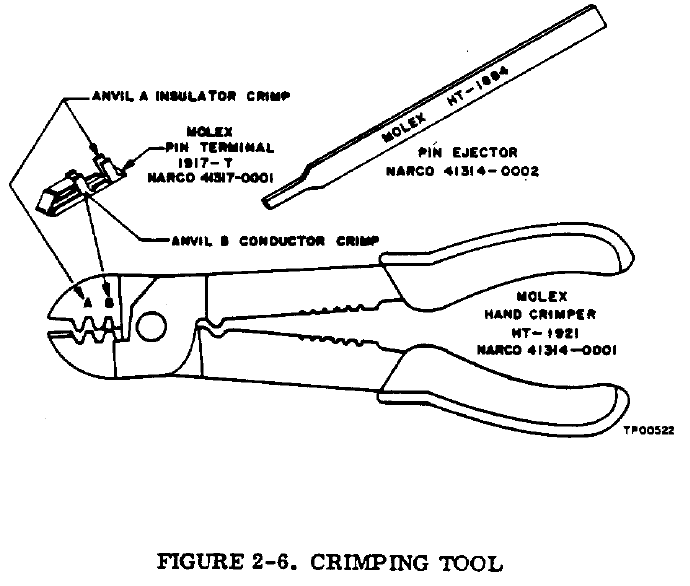
B. Molex Hand Crimper, HT-1921, Narco Part Number 41314-0001.
C. Molex Pin Ejector, HT-1884, Narco Part Number 41314-0002.
1.8 OPERATOR LICENSE REQUIREMENTS
The Federal Communications Commission requires that the transmitter in this equipment hold a Restricted
Radio Telephone Operator Permit, or a license of a higher class. A permit may be obtained by any U.S. Citizen
from the nearest field office of the FCC; no examination is required.
INTRODUCTION
SECTION 1
May, 2002 REV 1.0 1-5
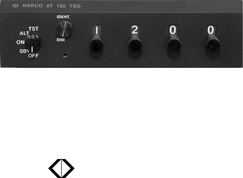
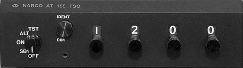
1.9 OPERATION
FIGURE 1-1 AT 155 FRONT PANEL
1.9.1 Function Selector Switch
The function selector is a five position rotary switch. The five positions are:
OFF- Turns OFF all power to the transponder.
SBY- Turns the transponder power supply ON. When in SBY, the transponder will not reply to any
interrogation.
SBY is used at the request of the air traffic controller to selectivity clear his scope of traffic.
ON- Places the transponder in Mode A, the aircraft identification mode. In addition to the aircraft's
identification code, the transponder will also reply to altitude interrogations (Mode C) with discreet
signals that do not contain altitude information.
ALT- The ALT position activates all the necessary circuitry (transponder to optional altitude digitizer and
return) to respond to ATC (Air Traffic Control) altitude interrogations and aircraft identification
interrogations with standard pressure altitude (29.92 inches Hg).
The ALT position may be used in aircraft that are not equipped with the optional altitude digitizer,
however, the only response will be discreet signals that do not contain altitude information.
TST- Turning the switch to the TST position injects a test signal into the transponder.
This test signal tests all transponder circuitry involved in a Mode A reply and causes the IDENT/DIM
button to come on at full brilliance. This full brilliance indicates that the transponder has the capability
of receiving and responding to interrogations. The TST function may be activated at any time, as it does
not interfere with normal operation.
The TST position is spring loaded and must be held in position during the test process. Upon release, it
will automatically return to the ALT position.
Narco Avionics AT155
1-6 REV 1.0 May, 2002
1.9.2 Ident/Dim
When the aircraft comes within range of a ground station, the IDENT/DIM button will blink ON and OFF.
Momentarily depressing the IDENT/DIM button will activate the SPIP (Special Position Identification Pulse)
signal for approximately 20 seconds. This signal will "paint" an instantly identifiable image on the controllers
scope. This signal must only be used upon request of a "Squawk IDENT" from the controller. Use at any other
time could interfere with another aircraft sending a SPIP. During "'IDENT" periods, the IDENT/DIM button
will glow constantly.
Rotating the IDENT/DIM button will control the intensity at which the button glows.
1.9.3 Code Selector
The CODE SELECTOR consists of four eight position switches that provide 4096 active identification codes.
The identification code is selected by the controller.
INSTALLATION
SECTION 2
May, 2002 REV 1.0 2-1
2.1 INTRODUCTION
This section provides the necessary information for the installation of the AT155 TSO and, where required,
optional accessories.
2.2 PRELIMINARY INSPECTION
2.2.1 Unpacking
Carefully unpack the Unit and inspect it for any damage that may have occurred during shipment. Refer to
Section 1.5, Units and Accessories Supplied, and inventory the contents of the Installation Kit. Refer to Section
1.7, Miscellaneous Items Required but NOT Supplied for a listing of items and equipment needed for proper
installation.
Narco Avionics AT155
2-2 REV 1.0 May, 2002
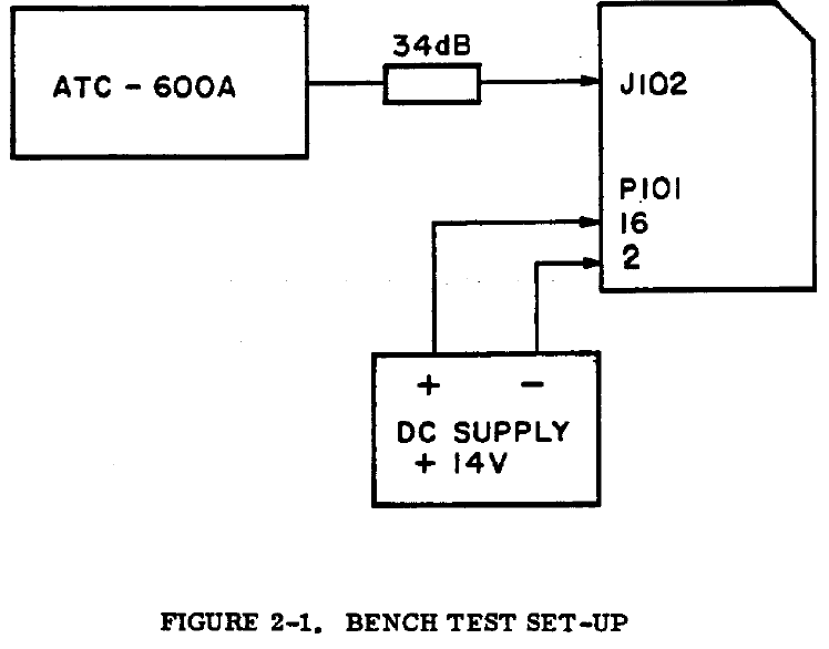
2.2.2 Electrical Bench Test
2.2.2.1 Test Equipment Required
A. Transponder and DME Test Set: IFR Model ATC-600A or equivalent.
B. 34 dB attenuation pad.
2.2.2.2 Test Procedure
A. Set-Up
1. The AT155 should be tested while contained in the mounting tray with the RF cable installed.
2. When the AT155 is being interrogated by the ATC-600A, the IDENT/DIM
button will blink ON and OFF.
B. Receiver Sensitivity
1. Place the AT155 in the ON mode. Place the ATC-600A in the A/C CODE mode.
2. Rotate the ATC-600A XPDR SIG. level control full counterclockwise. The % scale of the XPDRRPLY
meter should read 100%.
3. Rotate the XPDR SIG level control clockwise until the XPDR RPLY meter reads 90%.
4. The XPDR SIG level control indicator should be between -69 and -74 dBm. This is the MTL of the
transponder.
AT155
INSTALLATION
SECTION 2
May, 2002 REV 1.0 2-3
2.2.2.2 Continued
5. Repeat steps 2, 3, and 4 with the AT155 in the ALT mode and the ATC-600A in the A/C ALT
mode. The difference between the MTL readings should not be greater than 1 dBm.
C. SLS Side-Lobe Suppression
1. Place the AT155 in the ON mode. Place the ATC-600A in the A/C CODE mode.
2. Rotate the XPDR SIG. level control full counterclockwise. The XPDR RPLY meter should read 100%.
3. Set the XPDR SIG. level control to 3 dB above MTL level established in step B-4.
4. Set the SLS switch to 0 dB. The XPDR RPLY meter should read zero.
5. Set the SLS switch to 9 dB. The XPDR RPLY meter should read 90% minimum.
D. Code Selection
1. Place the AT155 in the ON mode. Place the ATC-600A to the A/C CODE mode.
2. The ATC-600A numerical display should display the code selected by the AT155 Code Selector
switches. Several different codes should be selected.
3. Consider the AT155 Code Selector switches to be labeled A, B, C, and D.
Switch A should light the ATC-600A Binary Readout lamp .A1 when it is in
the 1 position, the A2 lamp in the 2 position, and the A1 and A2 lamps in the
3 position. In each switch position, the sum of the subscripts of the Binary
Readout lamps that light should equal the number selected.
4. Repeat the above procedure for switches B, C, and D.
E. Transmitter Frequency
1. Place the AT155 in the ON mode and set the Code Selector switches to 0000.
2. Place the ATC-600A in the A/C CODE mode and set the POWER/FREQ switch to FREQ.
3. Adjust the GAIN control for a mid-scale reading on the POWER meter.
4. Rotate the XMTR FREQ control for a peak Indication on the POWER meter.
5. At peak, read the deviation from 1090 MHz directly from the XMTR FREQ
control dial. The deviation should be no greater then ±3 MHz.
F. Transmitter Power
1. Place the AT155 in the ON mode and set the Code Selector switches to 6050.
2. Place the ATC-600A in the A/C CODE mode and set the POWER/FREQ switch to POWER.
3. Read 190 watts (minimum) on the POWER meter.
G. Ident
1. Place the AT155 in the ON mode. Place the ATC-600A in the A/C CODE mode.
2. Momentarily depress the IDENT/DIM button on the AT155.
3. The AT155 IDENT/DIM button and the ATC-600A IDENT lamp should glow for approximately 20 ±5
seconds.

Narco Avionics AT155
2-4 REV 1.0 May, 2002
2.2.2.2 Continued
H. Altitude Digitizer Inputs
The following procedure is a functional check of the Altitude Digitizer Inputs
P101-6 through P101-14 only. Therefore, the numerical readout and INVALID
ALT lamp on the ATC-600A should be ignored.
1. Place the AT155 in the ALT mode. Place the ATC-600A in the A/C ALT mode.
2. Placing an Altitude Digitizer Input at ground potential will activate a corresponding Binary Readout
lamp on the ATC-600A. Table 2.1 lists the P101 pin numbers and their corresponding ATC-600A
Binary Readout lamps.
TABLE 2.1 ALTITUDE DIGITIZER INPUTS
GROUND
P101 ACTIVATE ATC-600A BINARY
READOUT LAMP
6A
2
7A
1
8A
4
9B
4
10 B2
11 C2
12 B1
13 C4
14 C1
Disconnect the transponder from the Test Set-Up.
INSTALLATION
SECTION 2
May, 2002 REV 1.0 2-5
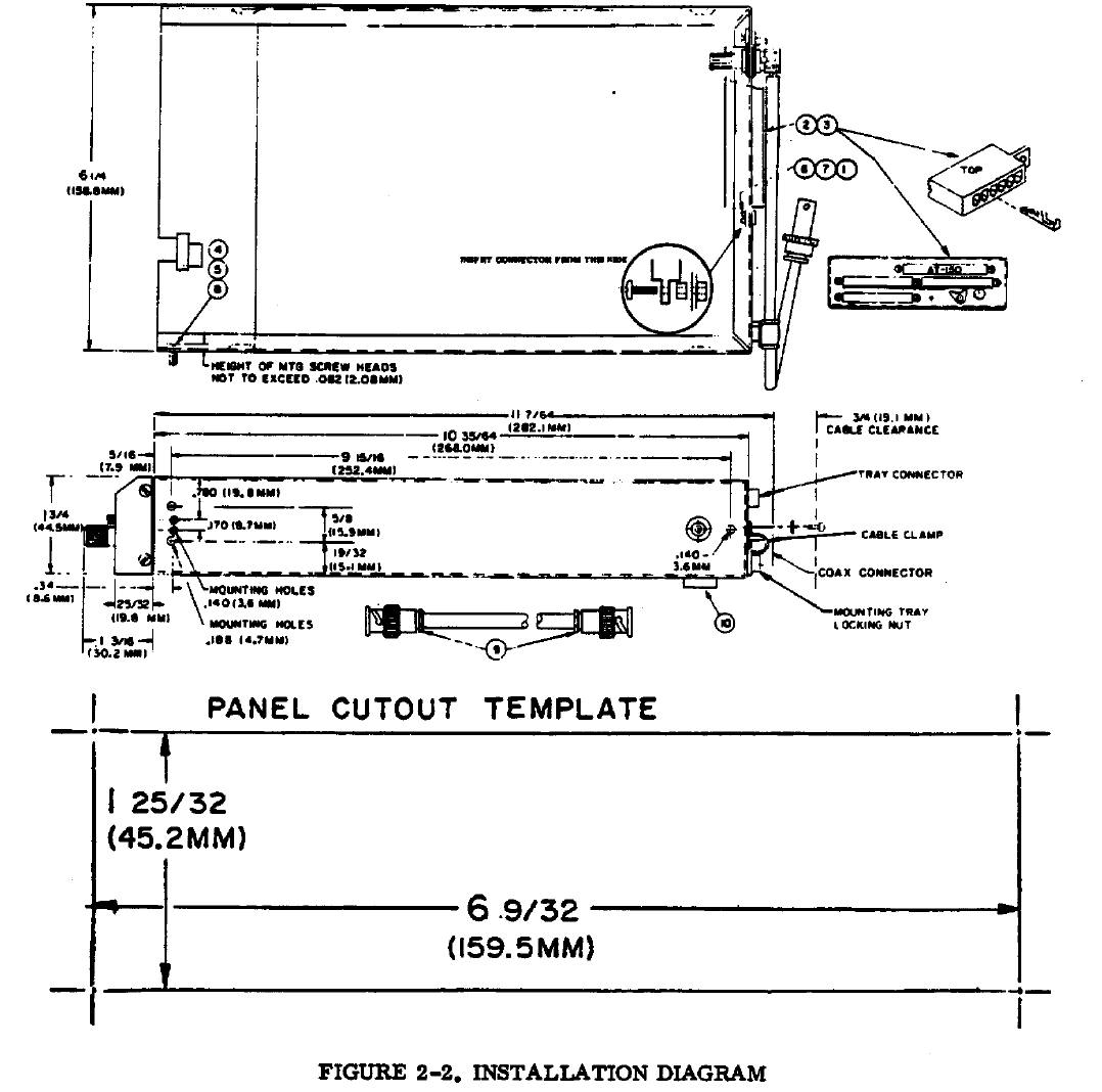
2.3 MECHANICAL INSTALLATION
2.3.1 Mounting Tray
The AT155 is supplied with a mounting tray which is designed to mount behind the aircraft instrument panel
using four number 6 screws. Figure 2-2 provides a detailed drawing of the tray and the parts of the Installation
Kit. This figure also provides all the necessary dimensions for the panel cutout as well as dimensions for
mounting brackets locations. A full scale cutout template is also provided.
Mounting brackets (4) are not supplied due to the wide range in mounting requirements. Suitable mounting
brackets may be fabricated from ordinary sheet metal or angle stock.
To ensure a sturdy mount, rear support for the unit should be provided.
2.3.2 Insertion And Removal Of The AT155
Before inserting the AT155 into the tray, refer to paragraph 2.5.4 and check that the PILOT LAMPS have been
wired properly.
The AT155 is secured to the mounting tray by a hex head ramping screw running from the front panel to the
rear of the unit and a self-locking nut attached to the tray rear panel. The access hole for the ramping screw is
located on the front panel below the IDENT/DIM button (see Figure 1-1).
Slide the Unit straight into the tray until the ramping screw contacts the self-locking nut. Using a 5/64" hex
wrench, turn the screw clockwise until the mating connector is engaged and the unit is firmly secured in the
tray.
DO NOT RAM THE UNIT INTO THE TRAY OR OVER TIGHTEN THE RAMPING SCREW.
To remove the unit, turn the ramping screw counterclockwise until it is clear of the self-locking nut and then
pull the unit straight out.
Narco Avionics AT155
2-6 REV 1.0 May, 2002
Refer to table 1.2 for installation kit.
INSTALLATION
SECTION 2
May, 2002 REV 1.0 2-7
2.4 ANTENNA INSTALLATION
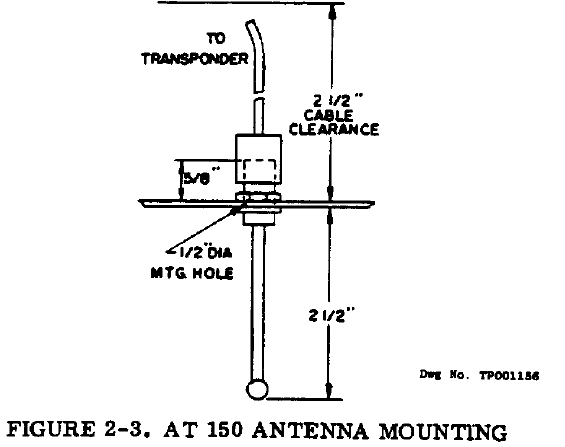
2.4.1 Antenna Location And Mounting
The AT155 Antenna supplied in the Installation Kit should be mounted on the bottom surface of the aircraft and
located such that it will be in a vertical position when the aircraft is in level flight. The area surrounding the
antenna location should be free of protrusions which could interfere with the line-of-sight characteristics of a
VHF signal. The following rules should be observed with regard to the ground plane.
A. Metallic Mounting Surface
Mount the antenna in the center of a 6" (152.4 mm), minimum radius, ground plane. Antenna located near
the edge of a ground plane may cause holes in the radiation and reception patterns.
B. Non-Metallic Mounting Surface
Aircraft with fabric, wood, or fiberglass fuselage covering must have a metal ground plane with a 6" (152.4
mm) minimum radius. This could be as simple as aluminum foil cemented inside wood or stiff fiberglass
skin, or a doubler plate on a fabric covered aircraft. Such a ground plane should be either well bonded to the
airframe, or well insulated from it, to prevent noise problems or erratic operation. Antenna mounting
hardware must electrically connect the ground plane to the antenna.
A doubler plate will be needed for an airworthy Installation on most aircraft. Check the airworthiness
regulations of the country of aircraft registry for acceptable mounting methods.
Figure 2-3 illustrates the antenna mounted and the necessary minimum clearances. Remove all oxidation, paint,
or other finish to permit good electrical contact between the antenna base and the aircraft. Electrical ground will
be carried by the mounting hardware.
DO NOT PAINT. The antenna should not be painted or coated with any other finish.
Narco Avionics AT155
2-8 REV 1.0 May, 2002
2.4.2 Antenna Extension Cable
The Installation Kit provides two UG-88U BNC connectors for fabrication of the antenna extension cable. The
total length of this cable should not exceed 9 feet (2.7m). Should a cable of greater length be required, a coaxial
cable type should be selected whose attenuation does not exceed 2 dB over the entire length.
INSTALLATION
SECTION 2
May, 2002 REV 1.0 2-9
2.5 ELECTRICAL INSTALLATION
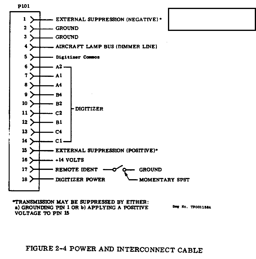
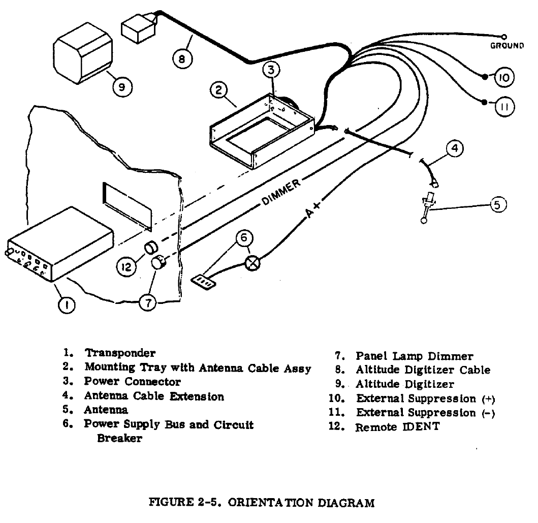
2.5.1 Power And Interconnect Cable
The Installation Kit provides an 18 pin Molex connector along with sufficient pins for fabrication of the power
and interconnect cable. Figure 2-4 presents the electrical connections and Figure 2-5 presents a system
orientation diagram.
All signal leads should be 22AWG. A+ and ground leads should be 16 AWG. The ground lead should be
connected directly to airframe ground.
A 1.5 amp circuit breaker should be provided between the unit and the aircraft power bus.
NOTE: Pin 1 is nearest
the center of the radio.
Narco Avionics AT155
2-10 REV 1.0 May, 2002
INSTALLATION
SECTION 2
May, 2002 REV 1.0 2-11
2.5.2 Cable Fabrication
1. Strip wire 5/32" for PIN Terminal No. 1917-T.
2. Open tool (Engraved side toward you), from the opposite side, place the conductor tab section of the pin
on Anvil B, Close tool slightly until the tabs touch the female jaw).
3. Insert stripped conductor until insulation is level with outside of jaw. Crimp by squeezing handles
together until jaws are fully closed or sufficient crimp is made.
4. Move lead and pin to Anvil A. Crimp again until jaws are closed or sufficient crimp is made.
5. If necessary, straighten pin while still being held in the jaw.
6. Insertion
a. The PIN terminal may now be inserted into the desired pin location in the translucent connector
housing. The pin cannot be inserted upside down. Right-side-up it slides in effortlessly. Be sure to
push it all the way in, until a "click" can be felt, heard, or even seen by turning the translucent
housing over.
b. There is no necessity to pull back on the lead itself except to test for the "locking feature", and then
only with a moderate pull.
Narco Avionics AT155
2-12 REV 1.0 May, 2002
2.5.2 Continued
7. Extraction
a. If a pin is erroneously inserted into the wrong housing position, or if at some later time a circuit
change is desired, the pin can be removed easily. Slip the flat narrow blade portion of the tool into
the mating side of the housing, under the pin. By holding the housing upside down one can see the
blade slide in, up to the stop. This action picks up the locking key and allows the lead and pin to slip
out of its position using a light pulling action on the lead. Neither pin nor position has been damaged
allowing re-insertion in the same or another position.
8. Crimping with Pliers
The lead PIN Terminal connection using the Molex hand crimper provides a superior connection than with
pliers. However, with care, a satisfactory connection can be made without the crimper.
a. Strip wire 5/32" for PIN Terminal 1917-T.
b. Using needle nose pliers, fold over conductor tabs firmly onto the conductor,
one side then the other.
c. Repeat step 2 for the Insulator tabs.
2.5.3 Pilot Lamps
Pilot lamp 14/28V OPERATION
The AT155 contain an external 14/28 vdc switch for this purpose. The switch, for proper lamp brilliance, should
be set to agree with that of the aircraft's bus voltage.
2.5.4 External Suppression
The AT155 transponder may be externally suppressed by other avionics equipment whose transmissions may be
interfered with by simultaneous AT155 transmissions. P101-15 may be connected to equipment that supply
positive suppression pulses. P101-1 may be connected to equipment that supply negative suppression pulses.
In aircraft equipped with dual transponders, P101-1 of both transponders may be connected to a remote SPDT
switch which will alternately suppress the transponders by placing the appropriate P101-1 at ground potential.
This switch may be located at any convenient place in the cockpit and labeled appropriately.
INSTALLATION
SECTION 2
May, 2002 REV 1.0 2-13
2.5.5 Remote IDENT
P101-17 provides for the connection of remote IDENT switch. This switch should be a momentary SPST type
and connected such that activation places P101-17 at ground potential. This switch may be located at any
convenient place in the cockpit and labeled appropriately.
2.5.6 Altitude Digitizer
P101 pins 5 through 14 provide for the connection of an altitude digitizer. The altitude digitizer, sensing
atmospheric pressure, converts pressure/altitude information into digitized altitude data. This data is then
transmitted to the control center by the transponder. Narco recommends the Model AR 850 for this application.
2.6 POST INSTALLATION TESTS
To certify the installation, FAA Form 337 must be completed. In addition, weight and balance or any operating
limitations must be entered into the aircraft logbook. Refer to the current Federal Aviation Regulations for any
additional requirements.
Weight 1.5 lbs. (0.68 kg)
Power Requirements 13.75 VDC 27.5VDC
Standby 210mA 125mA
Transmit 1.2 A 530mA
Pilot Lamps 220mA 90mA
2.6.1 Preflight Tests
A. A preflight test should be performed using an ATC-600A Transponder and DME test set or equivalent. The
test set should be set-up as described in the ATC-600A Operators Manual and following tests should be
conducted:
1. Pilot Code
2. Peak Transmitter Power
3. Transmitter Frequency
4. SLS Operation
5. IDENT
6. Percent Reply
B. In the event that an altitude digitizer has been installed, the altitude digitizer manual should be consulted for
proper procedures and the following tests should be conducted:
1. Altitude Code
2. Invalid Altitude Code Output
Narco Avionics AT155
2-14 REV 1.0 May, 2002
2.6.2 Flight Test
After installation, a flight test should be performed to check overall operation and system compatibility.
A. Range Test
1. The AT155 should furnish a strong and stable return signal to an interrogating radar facility that is 50 NM
away when the aircraft is flying at 6000 feet. At this altitude and distance, fly a flat circle while having a
FAA station monitor the transponder return signal. There should be no more than two sweeps of the
interrogating radar without a return response.
B. Surveillance Approach
1. Perform an approach to a runway of an airport starting at least 10 NM from the airport served by Airport
Surveillance Radar (ASR) having an Air Traffic Control Radar Beacon System (ATCRBS) facility.
Alternately, a simulated approach and letdown may be made along a path parallel to, but separated, three
to four miles from a vertical plane through the location of the ASR facility. The approach should be made
at the normal rate of decent and normal approach and landing configuration for the aircraft and should
continue down to an altitude of 200 feet. Not more than one "drop out" should occur for any 10 radar
sweeps during final approach.
C. Electromagnetic Compatibility
1. The transponder should not cause the performance of other systems aboard the aircraft to be degraded
below their normal capability and transponder operation should not be adversely affected by other
equipment.
2.7 AIRCRAFT LICENSE REQUIREMENTS
The AT155 installation must comply with current FCC transmitter licensing requirements. To find out specific
details on whether a particular installation requires licensing contact the FCC at 800-322-1117.
If an aircraft license is required, make application for a license on FCC form 404, Application for Aircraft
Radio Station License.
The aircraft owner accepts all responsibility for obtaining the proper licensing before using the AT155
This equipment has been type accepted by the FCC and entered in their list of type accepted equipment under
the FCC identifier “A9SAT155”.

INSTALLATION
APPENDIX
May, 2002 REV 1.0 A-1
APPENDIX A
A.1 ENVIRONMENTAL QUALIFICATION FORM
NOTE : A COPY OF THIS FORM IS TO BE FILED WITH THE OWNER'S AVIONICS RECORDS.
NOMENCLATURE : TRANSPONDER
MODEL : AT155
MANUFACTURER : Narco Avionics Inc.
ADDRESS : 270 Commerce Drive
Fort Washington, PA 19034
USA
CONDITIONS DO-160C
SECTION,
PARAGRAPH# DESCRIPTION OF CONDUCTED TESTS
Temperature and Altitude
Ground Survival Low Temperature
Operating Low Temperature
Ground Survival High Temperature
Short-Time High Operating
Temperature
Operating High Temperature
In Flight Loss of Cooling
Altitude
Decompression
Overpressure
4.0
4.5.1
4.5.1
4.5.2
4.5.2
4.5.3
4.5.4
4.6.1
4.6.2
4.6.3
Equipment tested to category "A1C1"
-55°C
-20°C
+85°C
+75°C
+55°C
Equipment tested to category "V", Greater than 30 Minutes
35,000 feet (10,668 meters)
8,000 feet to 35,000 feet ∆ within 15 seconds, then maintained for
10 minute minimum duration.
-15,000 feet for 10 minutes
Temperature Variation 5.0 Equipment tested to category "C".
Humidity 6.0 Equipment tested to category "A".
Operational Shocks and Crash Safety
Operational
Crash Safety
7.0
7.2
7.3
Equipment tested to operational and crash safety tests.
Vibration 8.0 Equipment tested without shock mounts to Categories M,
N and B (DO-160C Table 8-1)
Explosion 9.0 Equipment identified as Category "X", no test required.
Waterproofness 10.0 Equipment identified as Category "X", no test required.
Fluids Susceptibility 11.0 Equipment identified as Category "X", no test required.
Sand and Dust 12.0 Equipment identified as Category "X", no test required.
Fungus 13.0 Equipment identified as Category "X", no test required.
Salt Spray 14.0 Equipment identified as Category “X” , no test required.
Magnetic Effect 15.0 Equipment tested to Category "Z"
Power Input 16.0 Equipment tested to Category "B"
Voltage Spike 17.0 Equipment tested to Category "B"
Audio Frequency Susceptibility 18.0 Equipment tested to Category "B"
Induced Signal Susceptibility 19.0 Equipment tested to Category "A"
Radio Frequency Susceptibility 20.0 Equipment tested to Category "T"
Radio Frequency Emission 21.0 Equipment tested to Category "B"
Lightning Induced Transient Susceptibility 22.0 Equipment identified as Category "X", no test required.
Lightning Direct Effects Test 23.0 Equipment identified as Category "X", no test required.
Icing 24.0 Equipment identified as Category "X", no test required.
Other Test Fire resistance tests were conducted in accordance with Federal
Aviation Regulations Part 15, Appendix F.
Narco Avionics AT155
A-2 REV 1.0 May, 2002
A.2 CONTINUED AIRWORTHINESS
Other than for regulatory periodic functional checks, the AT155 does not require periodic maintenance.
If the AT155 exhibits non-conformal operation, the AT155 should be checked at a qualified service facility.

INSTALLATION
MANUAL REVISION HISTORY
May, 2002 REV 1.0 R-1
MANUAL REVISION HISTORY
Page
Number Revision
Level Date
i REV 1.0 MAY, 2002
ii REV 1.0 MAY, 2002
1-1 REV 1.0 MAY, 2002
1-2 REV 1.0 MAY, 2002
1-3 REV 1.0 MAY, 2002
1-4 REV 1.0 MAY, 2002
1-5 REV 1.0 MAY, 2002
1-6 REV 1.0 MAY, 2002
2-1 REV 1.0 MAY, 2002
2-2 REV 1.0 MAY, 2002
2-3 REV 1.0 MAY, 2002
2-4 REV 1.0 MAY, 2002
2-5 REV 1.0 MAY, 2002
2-6 REV 1.0 MAY, 2002
2-7 REV 1.0 MAY, 2002
2-8 REV 1.0 MAY, 2002
2-9 REV 1.0 MAY, 2002
2-10 REV 1.0 MAY, 2002
2-11 REV 1.0 MAY, 2002
2-12 REV 1.0 MAY, 2002
2-13 REV 1.0 MAY, 2002
2-14 REV 1.0 MAY, 2002
A-1 REV 1.0 MAY, 2002
A-2 REV 1.0 MAY, 2002
R-1 REV 1.0 MAY, 2002