Narco Avionics AT165 Aviation Transponder User Manual 423142
Narco Avionics Inc Aviation Transponder 423142
Contents
- 1. AT165 Installation Manual
- 2. AT165 Operation Manual
AT165 Operation Manual
PRINTED IN U.S.A. March, 2004
NARCO AVIONICS
AT165 TSO
Transponder
Operation Manual
03609-0621
NARCO AVIONICS INC.
270 Commerce Drive, Suite 200
Ft. Washington, PA. 19034
U.S.A.
NOTICE
While every effort has been made by Narco Avionics
Inc. to ensure accuracy in the preparation of this
Operation Manual, Narco assumes no responsibility
for errors or omissions
NARCO AVIONICS CAN BE REACHED BY CALLING:
215-643-2900
FAX: 215-643-0197
March, 2004 1
PRODUCT DESCRIPTION
The AT165 TSO is a panel-mounted transponder with additional altitude and timing functions. The AT165
consists of a receiver tuned to the frequency of a ground interrogation station (1030 MHz), logic circuitry to
check the validity of the received interrogation and encode a reply containing pertinent identification
information, and a transmitter, which sends the coded reply to the ground station. When connected to an
optional Altitude Digitizer (AR850) coded altitude information will be transmitted to the ground station.
The AT165 utilizes a single knob for error free code entry even in turbulence. Push button controls are used to
access and manipulate the added features. The front panel display has two distinct areas, one for the primary
transponder functions and the second for the altitude and timing functions.
The AT165 has been designed for 14V or 28V operation. If the AT165 is replacing an existing AT50TSO,
AT50A, AT150, or AT155 that uses an MP10 or a passive voltage converter, these do not need to be removed.
OPERATION
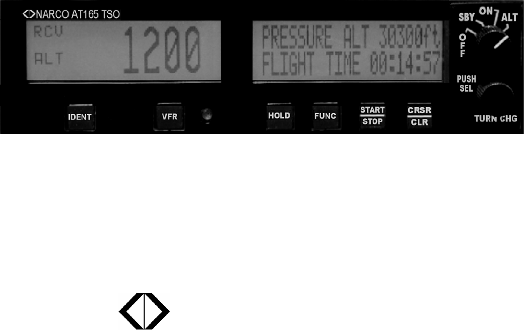
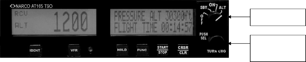
FIGURE 1-1 AT 165 FRONT PANEL
Function Selector Switch
The function selector is a four position rotary switch. The four positions are:
OFF- Turns off all power to the transponder.
SBY- Turns the transponder power supply on. When in SBY, the transponder will not reply to any
interrogation. SBY is used at the request of the air traffic controller to selectivity clear his scope of
traffic. When in this mode SBY will be shown on the Code display window.
ON- Places the transponder in Mode A, the aircraft identification mode. In addition to the aircraft's
identification code, the transponder will also reply to altitude interrogations (Mode C) with discrete
signals that do not contain altitude information. When in this mode ON will be shown on the Code
display window.
ALT- The ALT position activates all the necessary circuitry (transponder to optional altitude digitizer and
return) to respond to ATC (Air Traffic Control) altitude interrogations and aircraft identification
interrogations with standard pressure altitude (29.92 inches Hg). The ALT position may be used in
aircraft that are not equipped with the optional altitude digitizer, however, the only response will be
discrete signals that do not contain altitude information. When in this mode ALT will be shown on the
Code display window.
Function Selector
Switch
Code Selector /
Data Entry
Switch
2 March, 2004
SETUP
Start with the AT165 Function Selector Switch in the OFF position. Hold in the FUNC button while turning the
Function Selector Switch to the SBY position. Release the FUNC button. The AT165 will now be at the
Contrast Adjust screen. Rotating the Code Selector/Data Entry Switch CW or CCW will adjust the display’s
contrast. Once the desired contrast is achieved pressing the FUNC button will save this setting and continue to
the Display Mode screen.
The Display Mode screen allows three choices for the display: AUTO, POS or NEG. While in this mode,
turning the Data Entry Switch will scroll through these settings.
AUTO – Black letters on a light background switching to light letters on a black background as the
ambient light is reduced.
POS- Black letters on a light background.
NEG – Light letters on a black background.
Once the desired Display Mode setting is achieved pressing the FUNC button will save this setting and continue
to the Gray Code Input screen.
The Gray Code Input screen shows the current altitude and the status of each of the Gray code altitude inputs. A
filled box indicates a ground on the altitude input. This screen is used as an aid in installation troubleshooting.
Pressing the FUNC button exits the setup procedure.
CODE SELECTION
Pressing the Code Selector/Data Entry Switch once enables Transponder Code entry. The left most code digit
will begin flashing. Turning the switch selects the code and pushing the switch again moves to the next digit
from left to right. Once code selection has started, all four digits must be set before the code entry is completed.
A total of 5 pushes completes the code entry process. If the switch is inadvertently pressed, it will stop the code
entry process automatically in 10 seconds. The VFR code can subsequently be recalled automatically by
pressing the VFR button. Code entry can not be started if the AT165 is in setup, Count Down Timer set, or
Altitude Buffer set modes.

March, 2004 3
BUTTONS FOR ALTERNATE FEATURES
IDENT
Pressing the IDENT button will activate the SPIP (Special Position Identification Pulse) signal for
approximately 20 seconds. This signal will "paint" an instantly identifiable image on the controller’s scope.
This signal must only be used upon request of a "Squawk IDENT" from the controller. Use at any other time
could interfere with another aircraft sending a SPIP. The IDENT legend will appear in the Code window while
the Ident signal is being sent.
VFR
Pressing the VFR button will cause the squawk code to either change from the user entered code to a VFR code
or change back to the user entered code from the currently displayed VFR code. The last used squawk code is
automatically recalled when the unit is cycled off and on.
HOLD
Pressing the HOLD button will enter the Altitude Hold mode and lock the current altitude as the HOLD
altitude. The Altitude display area will now show the altitude difference relative to the HOLD altitude in 100ft
increments. The altitude display area will flash if the Altitude Buffer value is exceeded. Additionally if the audio
alert function has been installed, a warning will be heard. The audio warning will be present only while the unit
is in the Altitude Hold mode. This is a warning only and is not tied to any navigation systems.
Depressing the HOLD button for two seconds or longer will allow the setting of the Altitude Buffer. The
available range is 200ft to 2500ft. Once set, momentarily pressing HOLD again will save this buffer value. The
buffer value will be retained when the unit is powered off. This mode must be exited before other functions can
be accessed. Once started this mode will be exited when it has been inactive for 10 seconds.
FUNC
Pressing the FUNC button cycles the timer display between Flight Timer, Count Up Timer, and Count Down
Timer.
Holding the FUNC button in for 5 seconds or longer will Flip/Flop the left and right display areas. This
function is extremely useful in the unlikely event of an unreadable LCD display. When the unit is turned off it
will always restart with the displays in their default locations.
START/STOP
Pressing the START/STOP button will independently start or stop the Count Up and Count Down timers
depending on which is currently displayed.
CRSR/CLR
When in Flight Timer, depressing the CRSR/CLR button for two seconds will reset the Flight Timer.
When in Count Up Timer, depressing the CRSR/CLR button for two seconds will reset the Count Up Timer.
When in Count Down Timer, with the timer stopped, momentarily pressing the CRSR/CLR button once will
recall the preset count down time. Momentarily pressing this button again will activate the cursor in the timer
window. At this point, changes to the Count Down Timer value can be made by using the Code Selector/Data
Entry knob.

4 March, 2004
XXXXXXXXXXXXXX
FLIGHT TIME 00:00:00
XXXXXXXXXXXXXXX
COUNT UP 00:00:00
XXXXXXXXXXXXXXX
COUNT DOWN 00:00:00
TIMER OPERATION
FLIGHT TIME (Press FUNC until FLIGHT TIME is displayed)
The Flight Timer starts automatically when the AT165 is powered on. Pressing
and holding CRSR/CLR for two seconds will reset the Flight Timer to zero.
COUNT UP TIMER (Press FUNC until COUNT UP is displayed)
If necessary, press and hold CRSR/CLR for two seconds to reset the Count Up
Timer to zero.
Press START/STOP to begin counting up.
Press START/STOP to pause the Count Up Timer.
COUNT DOWN TIMER (Press FUNC until COUNT DOWN is displayed)
Press CRSR/CLR once to reload the previous Count Down Time.
Press CRSR/CLR a second time to activate the cursor.
Use the Code Selector/Data Entry switch to set the desired Count Down Time pressing the Code Selector/Data
Entry switch to complete each digit.
Press START/STOP to start the Count Down Timer.
Press START/STOP to pause the Count Down Timer.
When the Count Down Timer reaches zero and starts counting up, the Count Down Timer display will flash.
Additionally if the audio alert function has been installed a warning will be heard. The audio warning will be
present after the Count Down Timer has reached 00:00:00 and will continue until START/STOP and then
CRSR/CLR have been pressed.
NOTE: The Count Down Timer must be stopped before using CRSR/CLR to reset or change.

March, 2004 5
+0100ft HLD-> 01000ft
XXXXXXXXXXXXXX
LIMIT +-0000ft
XXXXXXXXXXXXXX
PRESSURE ALT 08500ft
XXXXXXXXXXXXXX
ALTITUDE DISPLAY
Displays the altitude data supplied to the AT165 from the blind altitude encoder.
ALTITUDE HOLD
HOLD MODE
Pressing HOLD will capture the Aircraft’s current altitude and use it as the
reference for the hold function. The altitude display will now show the
reference altitude and the deviation from that altitude in 100ft increments. If
the deviation exceeds the BUFFER limit, the altitude display will flash.
BUFFER SETTING
Pressing HOLD for greater than 2 seconds will allow setting of the HOLD
BUFFER value. Use the Data Entry switch to set the desired HOLD BUFFER
value. The HOLD BUFFER can be set from 200ft to 2500ft in 100ft steps.
When finished, press HOLD to save the HOLD BUFFER value.