National Datacomm 1022S01 22Mbps Cardbus Adapter User Manual Manual
National Datacomm Corporation 22Mbps Cardbus Adapter Manual
UserManual.wiki
>
National Datacomm
>
1022S01 User Manual
Manual
Navigation menu
Upload a User Manual
Namespaces
Wiki Guide
HTML
PDF
Info
Views
User Manual
Discussion / Help
Navigation

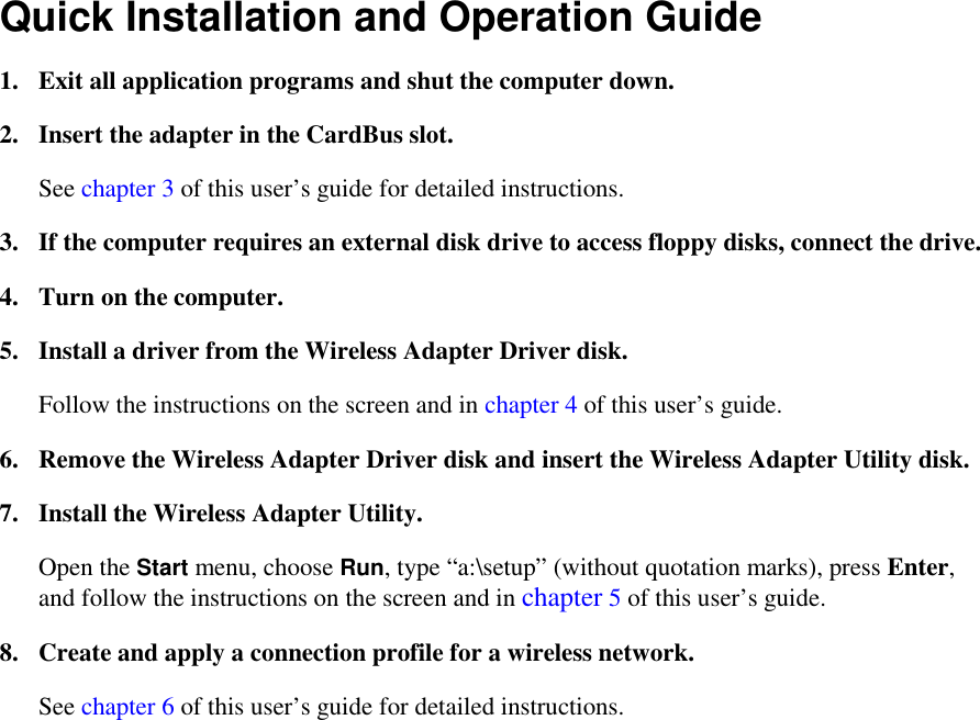

![8 • You will be able to move forward and back through the installation process by choosing the Next and Back buttons at the bottom of the window. • A number of options will appear during the installation process. You must select the options that tell the program: o You wish it to search for a driver. If you do not tell it to search for a driver, it will display a list that you will have to search through yourself. This list will be long and hard to understand, and it might not contain the correct driver. o You will specify the location (or one of the locations) to search. The program normally will not search on “removable media” such as a floppy disk. You must tell it in advance that you wish it to do so. o The location to search is a folder on the floppy disk in drive A. The Wireless Adapter Driver disk contains three folders. When the program displays a text input box for specifying a location, type in the name of the folder that corresponds to your version of Windows. Type a:\win2k if you are using Windows 2000. Type a:\win98 if you are using Windows 98 or Windows ME. Type a:\winxp if you are using Windows XP. • Always read everything in the window carefully, and make sure the correct options are selected, before choosing Next. • Avoid common mistakes. Be sure to — o Insert the disk at a suitable time (either when the program window appears, or when you type a folder name into the location box). o Insert the Wireless Adapter Driver disk (and not the Wireless Adapter Utility disk). o Type a backslash [\] after “a:” when specifying the location of the driver (do not type a slash [/]). For step-by-step instructions, see the appropriate part of the next section. 4.2 Installation Details Microsoft Windows 98: 1. Turn on the computer. Windows 98 will detect the adapter and start the Add New Hardware Wizard. 2. Choose Next. 3. Select “Search for the best driver for your device” and choose Next.](https://usermanual.wiki/National-Datacomm/1022S01/User-Guide-283275-Page-14.png)
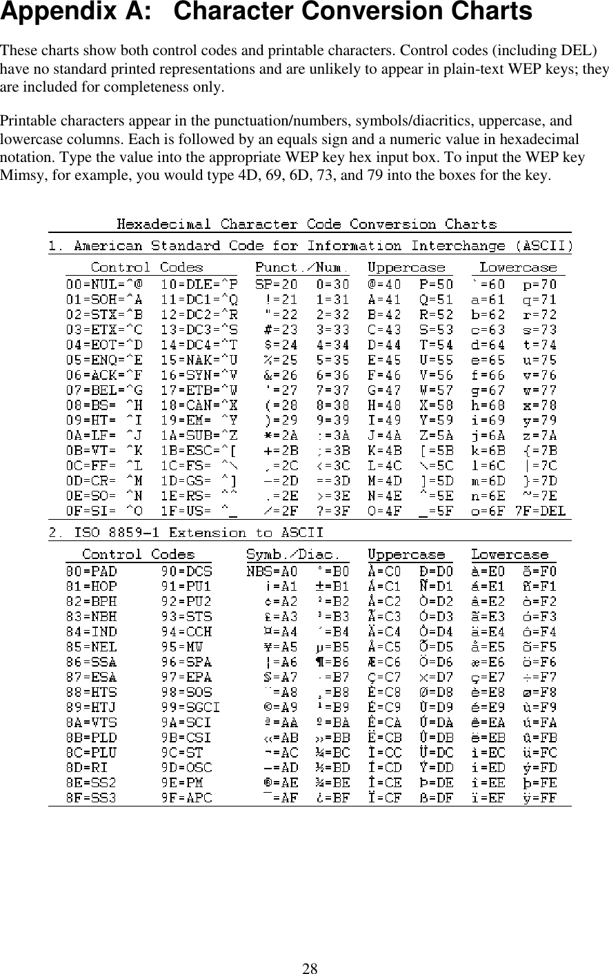
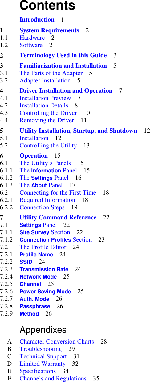
![29 Appendix B: Troubleshooting Problem: Adapter installation appears to have failed. Solutions: • Make sure the adapter is firmly seated in the CardBus slot. • Uninstall and reinstall the adapter. If the problem persists, uninstall the adapter and install it in another slot. If possible, try the adapter in another computer to see if the problem is in the adapter or the computer. • Check to see if there is an IRQ conflict with another device: 1. Open the Start menu, go to Settings, choose Control Panel, open the System icon, choose Device Manager, and open the Network adapters entry. If an exclamation mark [!] appears on the adapter icon, select the icon and choose Properties. 2. Under Conflicting device list in the Resources panel of the Properties dialog box, you will see a device conflict message. 3. Uncheck Use automatic settings and choose the Change Setting button. 4. Select a new IRQ value. When the message “No conflicts” appears in the Properties dialog box, close all windows by choosing OK, and then restart the computer. Problems: (1) The adapter fails to function. (2) The adapter’s LEDs are both off. (3) The operating system does not detect the adapter. Solution: These problems may be caused by unsuccessful installation. If you are sure that the adapter is firmly seated in a working slot and has not been turned off through the software, we recommend that you completely uninstall the adapter, the driver, and the utility, and then repeat the installation procedures described in this manual. Problem: You cannot join a network that currently appears in the Settings panel’s Site Survey section. Solution: Make sure the computer has the same SSID and security settings as the access point or (in the case of an ad-hoc network) whatever device represents the network in the Site Survey listing. • SSID: The SSID is case-sensitive. Every device on a wireless network must use exactly the same SSID. • Security: If the Site Survey list shows that WEP is disabled on the network, WEP must be disabled on your machine. If WEP is enabled on the network, it must be enabled with the same key length and contents on your machine. In addition, if WEP is enabled, the Auth. Mode control must be set to either Auto Switch or the mode used on the network (open authentication or shared authentication).](https://usermanual.wiki/National-Datacomm/1022S01/User-Guide-283275-Page-35.png)