National Datacomm 1022S01 22Mbps Cardbus Adapter User Manual Manual
National Datacomm Corporation 22Mbps Cardbus Adapter Manual
Manual
CardBus
Enhanced Wireless Network Adapter
User’s Guide
Version A1
August 2002
TRADEMARKS
All names mentioned in this document are trademarks or registered trademarks of their respective
owners.
DISCLAIMER
This document is provided “as is,” without warranty of any kind, either expressed or implied,
including, but not limited to, warranties of merchantability or fitness for a particular purpose. The
manufacturer may release improved or modified versions of this manual or any product or
program described in this manual at any time. This document could include technical inaccuracies
or typographical errors.
FCC WARNING
This equipment has been tested and found to comply with the limits for a Class B Digital device
pursuant to part 15 of the FCC Rules. These limits are designed to provide reasonable protection
against harmful interference in a residential installation. This equipment generates, uses, and can
radiate radio-frequency energy and, if not installed and used in accordance with the instructions,
may cause harmful interference to radio communications. However, there is no guarantee that
interference will not occur in a particular installation. If this equipment does cause harmful
interference to radio or television reception, which can be determined by turning the equipment
off and on, the user is encouraged to try to correct the interference by one or more of the
following measures:
• Reorient or relocate the receiving antenna.
• Increase the separation between the equipment and the receiver.
• Connect the equipment to an outlet on a circuit different from that to which the receiver is
connected.
• Consult the dealer or an experienced radio/TV technician for help.
You are cautioned that changes or modifications not expressly approved by the party responsible
for compliance could void your authority to operate the equipment.
This device complies with part 15 of the FCC Rules. Operation is subject to the following two
conditions:
• This device may not cause harmful interference, and
• This device must accept any interference received, including interference that may cause
undesired operation.
This transmitter must not be co-located or operated in conjunction with any other antenna or
transmitter.
Packing List
Your CardBus Enhanced Wireless Network Adapter package should contain the following items:
• One CardBus Enhanced Wireless Network Adapter
• One Wireless Adapter Driver disk
• One Wireless Adapter Utility disk
• One User’s Guide disk
Quick Installation and Operation Guide
1. Exit all application programs and shut the computer down.
2. Insert the adapter in the CardBus slot.
See chapter 3 of this user’s guide for detailed instructions.
3. If the computer requires an external disk drive to access floppy disks, connect the drive.
4. Turn on the computer.
5. Install a driver from the Wireless Adapter Driver disk.
Follow the instructions on the screen and in chapter 4 of this user’s guide.
6. Remove the Wireless Adapter Driver disk and insert the Wireless Adapter Utility disk.
7. Install the Wireless Adapter Utility.
Open the Start menu, choose Run, type “a:\setup” (without quotation marks), press Enter,
and follow the instructions on the screen and in chapter 5 of this user’s guide.
8. Create and apply a connection profile for a wireless network.
See chapter 6 of this user’s guide for detailed instructions.
Contents
Introduction 1
1 System Requirements 2
1.1 Hardware 2
1.2 Software 2
2 Terminology Used in this Guide 3
3 Familiarization and Installation 5
3.1 The Parts of the Adapter 5
3.2 Adapter Installation 5
4 Driver Installation and Operation 7
4.1 Installation Preview 7
4.2 Installation Details 8
4.3 Controlling the Driver 10
4.4 Removing the Driver 11
5 Utility Installation, Startup, and Shutdown 12
5.1 Installation 12
5.2 Controlling the Utility 13
6 Operation 15
6.1 The Utility’s Panels 15
6.1.1 The Information Panel 15
6.1.2 The Settings Panel 16
6.1.3 The About Panel 17
6.2 Connecting for the First Time 18
6.2.1 Required Information 18
6.2.2 Connection Steps 19
7 Utility Command Reference 22
7.1 Settings Panel 22
7.1.1 Site Survey Section 22
7.1.2 Connection Profiles Section 23
7.2 The Profile Editor 24
7.2.1 Profile Name 24
7.2.2 SSID 24
7.2.3 Transmission Rate 24
7.2.4 Network Mode 25
7.2.5 Channel 25
7.2.6 Power Saving Mode 25
7.2.7 Auth. Mode 26
7.2.8 Passphrase 26
7.2.9 Method 26
Appendixes
A Character Conversion Charts 28
B Troubleshooting 29
C Technical Support 31
D Limited Warranty 32
E Specifications 34
F Channels and Regulations 35
Figures
1. Ad-hoc network 3
2. Infrastructure network 3
3. Roamable multi-AP infrastructure network 4
4. CardBus Enhanced Wireless Network Adapter 5
5. Microsoft Windows 98 Add New Hardware Wizard window 7
6. Driver icon in system tray/notification area 10
7. Driver icon menus (1): main button 10
8. Driver icon menus (2): secondary button 11
9. Utility icons in the Start menu and on the desktop 13
10. Utility icon in the system tray/notification area 13
11. Closing the utility’s main window 14
12. Shutting down the utility 14
13. Typical Information panel display on first startup 16
14. The Settings panel in a multi-network environment 17
15. The About panel 18
16. The New Profile dialog box 20
17. 64-bit WEP key input boxes and controls 21
1
Introduction
Congratulations on choosing an outstanding wireless networking product. Your CardBus
Enhanced Wireless Network Adapter conforms to Institute of Electrical and Electronics
Engineers (IEEE) standard 802.11b and the Wi-Fi specification of the Wireless Ethernet
Compatibility Alliance (WECA). It supports data rates of up to 11 megabits per second (Mbps)
and 40- and 128-bit Wired Equivalent Privacy (WEP) encryption, and will interoperate
seamlessly with all other 802.11b and Wi-Fi compliant products.
Your adapter also supports Packet Binary Convolutional Code (PBCC) modulation and 256-bit
encryption. It can therefore provide a higher data rate (22 Mbps), increased throughput, up to 30
percent greater range, and stronger security than other 802.11b-compliant adapters. These
capabilities can be used on wireless links to products in the same family as your adapter.
This guide contains detailed instructions on installing and using your adapter and the software
included with it. Basic terms and concepts of wireless networking are also introduced. Follow the
instructions in this guide carefully to ensure that your CardBus Enhanced Wireless Network
Adapter will give you many years of trouble-free, high-performance operation.
2
1 System Requirements
Before installing the adapter and related software, make sure the computer system meets the
minimum requirements described below.
1.1 Hardware
The adapter can be installed in any recent-model IBM-type microcomputer with a CardBus slot,
also known as a PCMCIA or PC Card slot. The adapter is a Type II CardBus card, and can be
installed in a Type II or Type III CardBus slot.
The computer must have a 3.5-inch floppy-disk drive to allow installation of the driver and utility
software for the adapter.
1.2 Software
The drivers included with the adapter allow the adapter to be used in Microsoft Windows 98, ME,
2000, and XP. Third-party drivers may allow the adapter to be used, with reduced functionality,
in other operating systems.
3
2 Terminology Used in this Guide
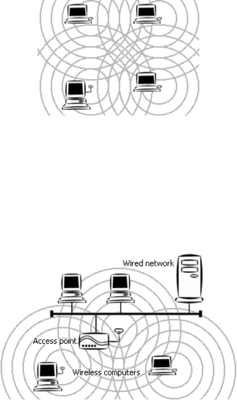
Ad-hoc Network
An ad-hoc network is a wireless local-area network (WLAN) made up of stations
communicating directly with each other through their wireless interfaces. There is no central
relay point, and normally no connection to a wired network. Ad-hoc mode is sometimes
referred to as peer-to-peer, computer-to-computer, or Independent Basic Service Set (IBSS)
mode. Figure 1 shows a typical ad-hoc network.
Figure 1. Ad-hoc network
Infrastructure Network
An infrastructure network is a WLAN made up of wireless stations and at least one wireless
relay point, known as a base station or access point (AP). The AP usually has a connection
to a wired network, allowing wireless stations to use resources on that network. The AP also
relays all communications between wireless stations in its coverage area; these stations
never communicate directly with each other. Infrastructure mode is sometimes referred to as
managed or Basic Service Set (BSS) mode. Figure 2 shows a typical infrastructure network.
Figure 2. Infrastructure network
BSSID/MAC Address
A Basic Service Set (BSS) is two or more wireless devices that are in communication with
each other. Like every wired Ethernet device, every wireless device has a fixed, unique
“medium access control” (MAC) address. When wireless devices establish communication,
4
they automatically select the MAC address of one BSS member as an identifier for the
group; this is the BSSID.
It has become customary to refer to a wireless device’s MAC address as its BSSID even
when the address is not being used to identify an active BSS.
A BSS that includes an access point is often referred to as a cell.
SSID/Domain Identifier
A Service Set Identifier (SSID) is a shared name, usually assigned by a network
administrator, that identifies wireless devices that are allowed to communicate with each
other. This is one way of providing basic security on a wireless network. An SSID can be up
to 32 characters long, and can include letters and numbers.
Giving multiple access points the same SSID and encryption settings allows mobile stations
that also share those settings to “roam” from one AP to another. When at least one AP is
among the devices sharing an SSID, the name may be referred to as an Extended Service Set
Identifier (ESSID).
An SSID is sometimes called a “domain name,” but it is unrelated to the domain names used
to identify machines and networks on the Internet. Other terms for SSID are domain ID, net
ID, network name, extended network ID, and wireless network name. The set of devices that
an SSID identifies is sometimes called a communication domain or wireless domain.
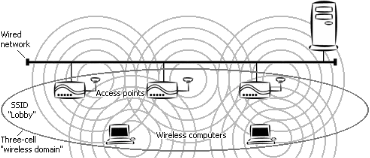
Figure 3 shows a common wireless network setup. If the APs share SSID and encryption
settings, mobile devices that also share those settings can roam among them.
Figure 3. Roamable multi-AP infrastructure network
Roaming
When APs covering adjacent areas have the same SSID and encryption settings, a mobile
device that also shares those settings can communicate through the APs continuously while
moving from one coverage area to another. This is known as roaming. When one AP’s
signal begins to weaken, the mobile device automatically searches for another AP that it is
authorized to “associate with” (that is, connect to); when the second AP’s signal quality is
better than that of the first, the station automatically switches over.
5
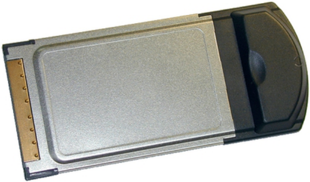
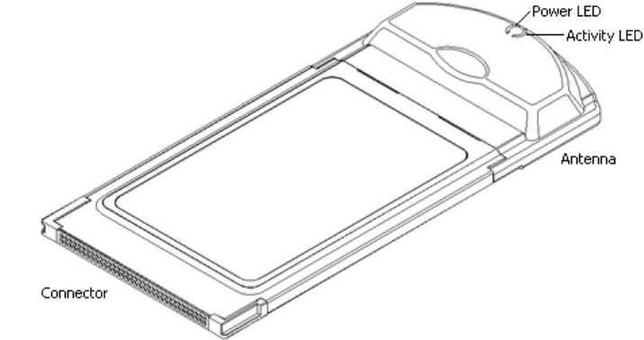
3 Familiarization and Installation
This chapter describes the adapter and gives instructions on inserting it for the first time.
3.1 The Parts of the Adapter
The adapter has a thin, rectangular end with 68 connector holes, and a thick, rounded end that
contains the antenna and two light-emitting diode (LED) indicators.
Figure 4. CardBus Enhanced Wireless Network Adapter
The connector end will fit only in a Type II or Type III CardBus slot (also called a “PCMCIA” or
“PC Card” slot) that provides the correct voltage level for the adapter.
The antenna housing will extend outside the slot when the adapter is fully inserted. The LEDs
indicate power and wireless network activity. When the antenna housing faces right like a capital
letter D, the power LED is above the activity LED. The LEDs work as follows:
• The power LED shines green when the adapter is receiving power from the computer.
Note that power to the adapter can be turned off and on through software.
• The activity LED shines orange when the adapter is transmitting or receiving.
3.2 Adapter Installation
On most computer systems, the adapter can be safely inserted or removed at any time. Certain
cautions should, however, be noted:
• If the adapter is inserted or removed while the computer is running, the operating system
may beep very loudly even if the sound control has been set to Mute or Muted.
6
• If the adapter will be connected to an extender card installed in a desktop computer, make
sure the extender card is firmly bolted to the computer’s housing before inserting or
removing the adapter. Shifting or rocking of a loose extender card can result in
momentary loss of contact, which can permanently damage sensitive electronic
components.
• Microsoft Windows lets you turn off power to the adapter before removing it. Depending
on your version of Windows, this may be called “stopping” or “disabling” the adapter. It
is strongly recommended that you use this function and avoid removing the adapter while
it is operating.
For installation of adapter software to go smoothly, follow the steps below when inserting the
adapter for the first time.
1. Have the Wireless Adapter Driver disk, the Wireless Adapter Utility disk, and your
Microsoft Windows CD-ROM ready.
The operating system might request the CD-ROM so it can install networking
components. The CD-ROM’s contents may have been copied to the hard disk during
system installation; if you know the path to the copy on the hard disk, you will be able to
supply that path instead of inserting the CD-ROM.
2. Exit all application and utility programs and shut down the computer.
3. If the computer uses an external floppy-disk drive, connect the drive as described in
the manual for the computer.
4. With the computer turned off, insert the adapter in the CardBus slot.
The location of the CardBus slot depends on the make and model of the computer. See
your computer manual for details. The manual might refer to the slot as a PCMCIA or PC
Card slot.
Most CardBus slots have a button for removing adapters. The button is normally flush
with the housing of the computer. Press and release it to make it extend outside the
housing; press it again to eject an adapter from the slot. A third press will return it to its
original position.
7
4 Driver Installation and Operation
After physically installing the adapter in the computer as described above, you are ready to install
a driver. This is software that lets the adapter be used in a specific operating system. The Wireless
Adapter Driver disk included with your adapter contains drivers for Microsoft Windows 98, ME,
2000, and XP.
The following note is for technicians experienced at installing drivers in Microsoft Windows.
Other readers should go directly to section 4.1, “Installation Preview,” immediately following the
note.
Note to technicians: The files on the driver disk reside in directories named
according the version of Windows the files are for: \WIN2K, \WIN98, and
\WINXP. For Windows ME, use the files in \WIN98. Although Windows XP has
a built-in driver for the adapter, the supplied utility program will work only if the
supplied driver is installed and activated.
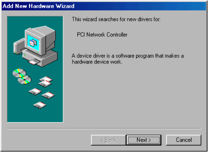
4.1 Installation Preview
When Microsoft Windows detects a newly installed adapter, it starts up a special program to help
you install a driver. Below is the opening window of the program that runs in Windows 98:
Figure 5. Microsoft Windows 98 Add New Hardware Wizard window
Each version of Windows has a different “wizard” for installing new drivers. To explain and
illustrate all the steps required in each version would fill up this entire manual. The following tips
apply to all supported versions of Windows; keep them firmly in mind, and you will have no
trouble installing the driver:
8
• You will be able to move forward and back through the installation process by choosing
the Next and Back buttons at the bottom of the window.
• A number of options will appear during the installation process. You must select the
options that tell the program:
o You wish it to search for a driver.
If you do not tell it to search for a driver, it will display a list that you will have
to search through yourself. This list will be long and hard to understand, and it
might not contain the correct driver.
o You will specify the location (or one of the locations) to search.
The program normally will not search on “removable media” such as a floppy
disk. You must tell it in advance that you wish it to do so.
o The location to search is a folder on the floppy disk in drive A.
The Wireless Adapter Driver disk contains three folders. When the program
displays a text input box for specifying a location, type in the name of the folder
that corresponds to your version of Windows. Type a:\win2k if you are using
Windows 2000. Type a:\win98 if you are using Windows 98 or Windows ME.
Type a:\winxp if you are using Windows XP.
• Always read everything in the window carefully, and make sure the correct options are
selected, before choosing Next.
• Avoid common mistakes. Be sure to —
o Insert the disk at a suitable time (either when the program window appears, or
when you type a folder name into the location box).
o Insert the Wireless Adapter Driver disk (and not the Wireless Adapter Utility
disk).
o Type a backslash [\] after “a:” when specifying the location of the driver (do not
type a slash [/]).
For step-by-step instructions, see the appropriate part of the next section.
4.2 Installation Details
Microsoft Windows 98:
1. Turn on the computer. Windows 98 will detect the adapter and start the Add New
Hardware Wizard.
2. Choose
Next.
3. Select “Search for the best driver for your device” and choose Next.
9
4. Check “Floppy disk drives” and “Specify a location,” and uncheck all other options; then
type the following into the location box: a:\win98
5. Insert the Wireless Adapter Driver disk in drive A and choose Next. The Add New
Hardware Wizard will find the driver and show information about it.
6. Choose
Next. Installation will begin.
7. Follow the on-screen instructions to finish.
Microsoft Windows ME (uses the Windows 98 driver):
1. Turn on the computer. Windows ME will detect the adapter and start the Add New
Hardware Wizard.
2. Select “Specify the location of the driver (Advanced)” and choose Next.
3. Make sure “Search for the best driver for your device (Recommended)” is selected; under
it, check both “Removable Media (Floppy, CD-ROM....)” and “Specify a location”; then
type the following into the location box: a:\win98
4. Insert the Wireless Adapter Driver disk in drive A and choose Next. The Add New
Hardware Wizard will find the driver and show information about it.
5. Choose
Next. Installation will begin.
6. Follow the on-screen instructions to finish.
Microsoft Windows 2000:
1. Turn on the computer. Windows 2000 will detect the adapter and start the Found New
Hardware Wizard.
2. Choose
Next.
3. Select “Search for a suitable driver for my device” and choose Next.
4. Select “Specify a location” and choose Next.
5. Insert the Wireless Adapter Driver disk in drive A and type the following into the
location box: a:\win2k
6. Choose
Next. The Found New Hardware Wizard will find the driver and display
information about it.
7. Choose
Next; then choose Yes. Installation will begin.
8. When the Found New Hardware Wizard indicates that installation is complete, choose
Finish.
10
Microsoft Windows XP:
1. Turn on the computer. Windows XP will detect the adapter and start the Found New
Hardware Wizard.
2. Insert the Wireless Adapter Driver disk and select “Install from a list or specific location
(Advanced)”; then choose Next.
3. Check “Include this location in the search” and type the following into the location box:
a:\winxp
4. Choose
Next. Installation will begin.
5. When the Found New Hardware Wizard indicates that installation is complete, choose
Finish.
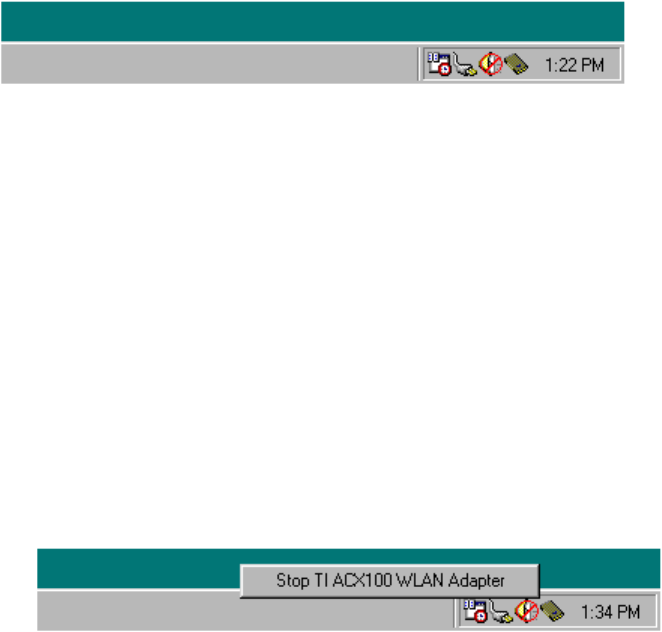
After the driver is installed, an icon of a CardBus adapter will appear in the “system tray” or
“notification area” of the task bar. The following illustration is from Microsoft Windows 98; the
corresponding portion of your screen may look quite different:
Figure 6. Driver icon in system tray/notification area
4.3 Controlling the Driver
The driver normally works automatically:
• When the computer is turned on with the adapter inserted, the driver is loaded and its
icon appears in the “system tray” (also called the “notification area”).
• When the computer is turned on with the adapter removed, the driver is not loaded and its
icon does not appear.
You can also control the driver and the adapter as follows:
• To deactivate the driver: Click the driver’s icon using the mouse’s main button
(usually the left button) and choose Stop TI ACX100 WLAN Adapter.
Figure 7. Driver icon menus (1): main button
This will unload the driver from the computer’s memory and turn off power to the
adapter. The message “You may safely remove this device” will appear; choose OK to
continue.

11
• To reactivate the driver: Open the Start menu, go to Settings, choose Control Panel,
open the Add New Hardware (or Add Hardware) icon, choose Next, choose Next again,
and press Esc.
Assuming the adapter is in the slot, the driver will be activated and the adapter will start
working. Note that the system may stop responding to keyboard and mouse actions for
about one minute.
• To hide the driver’s icon without deactivating the driver: Click the icon using the
mouse’s secondary button (usually the right button) and choose Disable PC Card Tray
Icon.
Figure 8. Driver icon menus (2): secondary button
• To unhide the driver’s icon: Open the Start menu, go to Settings, choose Control
Panel, open the PC Card (PCMCIA) icon, select the adapter, check the “Show control on
taskbar” box, and choose OK.
The dialog box that appears when you open the PC Card (PCMCIA) icon contains
adapter-related functions provided by the operating system. Some are self-explanatory;
others are highly technical. There are two other ways to open this dialog box:
o double-click the driver’s icon, or
o click the icon with the mouse’s secondary button (usually the right button) and
choose Adjust PC Card Properties.
If you wish to remove the adapter while the computer is running, it is strongly recommended that
you first deactivate the driver as described above.
4.4 Removing the Driver
If you wish to remove the driver from the system, do so as described below. It is assumed here
that the adapter has already been removed.
1. Open the
Start menu, go to Settings, choose Control Panel, and open the Network icon.
2. In the list of network components, select TI ACX100 WLAN Adapter.
3. Choose
Remove.
You will be asked for confirmation and instructed to reboot the computer.
12
5 Utility Installation, Startup, and Shutdown
To join and leave wireless networks and use the adapter’s special features, you must install the
utility included with the adapter. In addition to its basic functions, this utility has special features
that make wireless networking as convenient as possible.
5.1 Installation
Before installing the utility, make sure all items on the following checklist have been completed:
• The adapter is installed and its LEDs light up.
• The driver is installed and its icon appears in the system tray (also known as the
notification area).
• If the computer has no built-in floppy-disk drive, an external drive is connected.
Install the utility as follows:
1. Exit all application and utility programs.
2. Insert the Wireless Adapter Utility disk in the floppy-disk drive.
3. Open the
Start menu, choose Run, and type the following into the input box labeled
Open: a:setup
4. Press the
Enter key (or choose OK).
5. Follow the instructions on the screen.
The installation program ordinarily places the Wireless Adapter Utility in the following
location on your hard disk:
C:\Program Files\Wireless\Wireless Adapter Utility
It also normally adds a folder icon to the Start menu’s Programs submenu labeled
Wireless Adapter Utility. Commands to start and uninstall the Wireless Adapter Utility
will appear when you choose this folder icon.
You will be given a chance to specify other locations for the utility on your hard disk and
in the Start menu. After you have indicated your choices, the utility will be installed and
a dialog box titled Setup Complete will appear.
6. Choose
Finish.
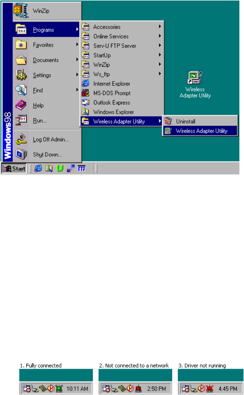
Icons for the Wireless Adapter Utility will appear on your desktop and in the Start menu. The
following example is from a computer running Microsoft Windows 98; the appearance of these
items on your screen might be different.
13
Figure 9. Utility icons in the Start menu and on the desktop
5.2 Controlling the Utility
The Wireless Adapter Utility behaves slightly differently from most programs with icons on the
desktop and in the Start menu. Take note of the following so you will know what to expect when
you start using the utility:
• You can start the utility up in either of two ways:
o by opening the Start menu, going to Programs, choosing the Wireless Adapter
Utility folder, and choosing the Wireless Adapter Utility command, or
o by choosing the Wireless Adapter Utility icon on the desktop.
• When the utility is running, its icon appears in the system tray (also known as the
notification area).
This icon has three states: (1) A green screen and radio waves show that you are
connected to a wireless network. (2) A red screen and absence of radio waves show that
the adapter and driver are working, but a wireless connection cannot be established. (3) A
red X covering the icon shows that the driver is not running.
Figure 10. Utility icon in the system tray/notification area
14
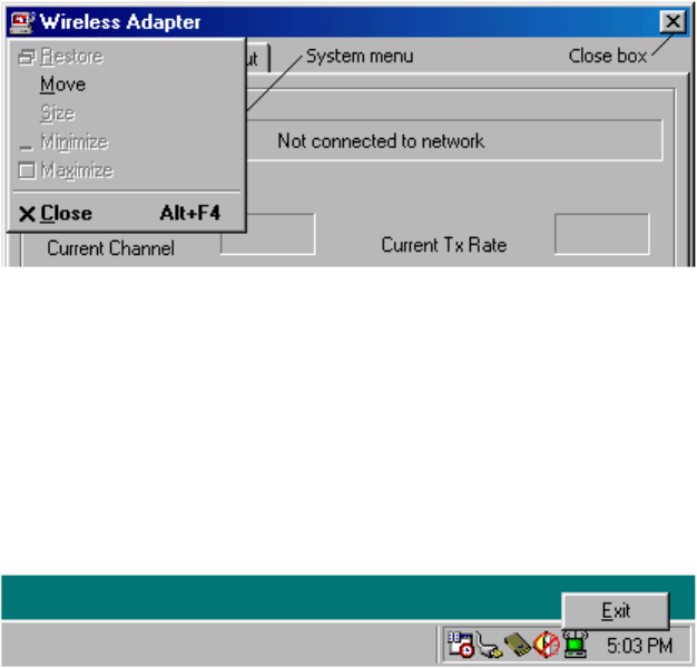
• When you close the utility’s main window in any of the usual ways (clicking its close
box, choosing Close from its system menu, or pressing Alt+F4), the utility continues to
run in the background.
The utility must be running to keep any wireless connections active.
Figure 11. Closing the utility’s main window
• To re-open the utility window, you can double-click the utility icon in the system tray, or
you can carry out either of the procedures for starting the utility up (see first item above).
None of these actions will cause multiple instances of the utility to run at the same time.
• To shut the utility down, click the utility’s icon in the system tray with the mouse’s
secondary button (usually the right button) and choose the Exit command.
Figure 12. Shutting down the utility
Note that shutting down the utility will also shut down any existing wireless connections.
15
6 Operation
This chapter explains how to establish wireless connections using your CardBus Enhanced
Wireless Network Adapter and the Wireless Adapter Utility. It is assumed here that —
• you have completed installation of the adapter, driver, and utility;
• you know how to start the utility, close and redisplay its window, and shut it down (see
section 5.2, “Controlling the Utility”); and
• you are within range of at least one wireless device that is working and will accept a
connection from you.
Any wireless connection, even a connection to a single device, is treated in this chapter as a
connection to a wireless network. There is, in fact, no difference in the steps required to connect
wirelessly to a single device or a whole network, and a connection to a single device is in fact a
true network connection.
6.1 The Utility’s Panels
The utility has three panels: Information, Settings, and About. Illustrations and brief
explanations of these panels are given below.
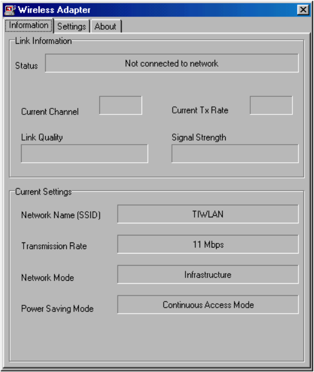
6.1.1 The Information Panel
The Information panel shows information about any active wireless link and the settings of four
important wireless networking controls. The figure below shows the usual appearance of this
panel the first time you start the utility up.
16
Figure 13. Typical Information panel display on first startup
Note the default setting shown in the Network Name (SSID) box. If the adapter had been within
range of an access point (AP) that used the same SSID and did not require encryption, a
connection would have been automatically established. This panel then would have shown the
AP’s SSID and BSSID, as well as the current channel, transmission rate, link quality, and signal
strength.
(The terms SSID, BSSID, and infrastructure are explained in chapter 2, “Terminology Used in
this Guide,” and in section 7.1.1, “Site Survey Section.” Channels and transmission rates are also
explained in section 7.1.1. Mbps stands for megabits per second.)
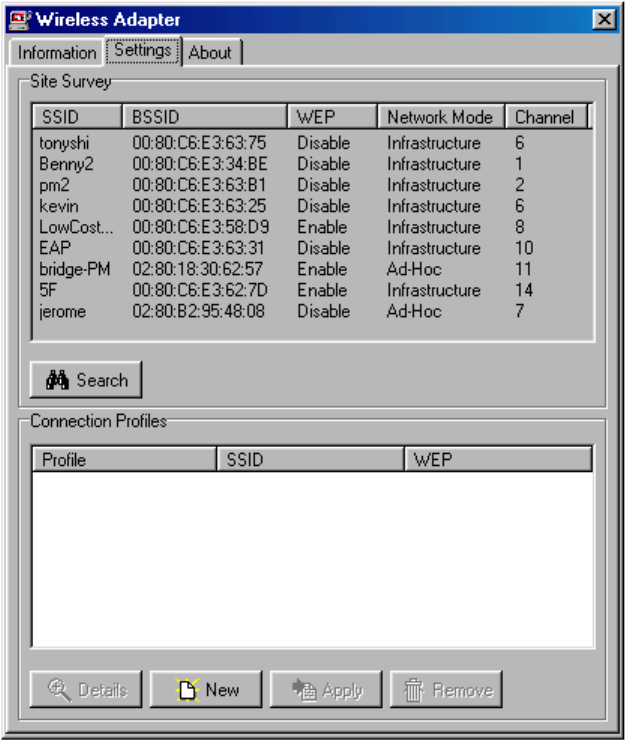
6.1.2 The Settings Panel
Choosing the Settings tab displays the Settings panel. This panel has a Site Survey section and
a Connection Profiles section.
17
Figure 14. The Settings panel in a multi-network environment
The Site Survey section shows all wireless networks and devices that the adapter is currently
receiving signals from. This information is updated each time the Settings panel is opened; you
can also update it by choosing the Search button.
A “connection profile” is a group of settings that allows you to join a particular wireless network.
You can create, save, edit, and remove profiles for as many wireless networks as you need to
connect to; then, when you are within range of any one of them, all you have to do to join the
network is “apply” the profile for it.
Basic profile management is explained in section 6.2, “Connecting for the First Time.”
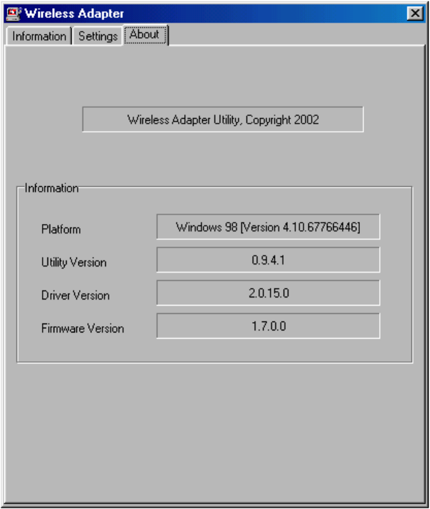
6.1.3 The About Panel
The About panel contains copyright, platform, and version information. The version numbers of
the utility, the driver, and the adapter’s firmware are all displayed.
18
Figure 15. The About panel
6.2 Connecting for the First Time
A connection to a wireless network is made by creating, saving, and applying a profile for that
network. This is done through the Wireless Adapter Utility’s Settings panel.
6.2.1 Required Information
Before you create a connection profile, you need to know certain information about the wireless
network that the profile is for:
• The SSID, sometimes referred to as the network name or ID, or the domain name or ID.
If you are within range of the network, you can obtain the SSID from the Settings
panel’s Site Survey section. If it exceeds the width of the SSID column, place the pointer
on it (or drag the BSSID column to the right) to see all of it.
Note: On some infrastructure networks where unusually tight security is
enforced, SSID broadcasts (also known as “beacons”) are disabled. Such
a network will not appear in the Site Survey listing, and you may not be
able to connect to it even if you know the SSID.
19
• The operating mode of the network. This can be 802.11 ad-hoc, infrastructure, or high-
speed ad-hoc. The Site Survey display will show you if a network is in ad-hoc or
infrastructure mode.
o If the mode is ad hoc (either 802.11 or high-speed), you will need to know the
radio frequency channel the network is operating on. This is displayed in the Site
Survey listing.
o High-speed ad-hoc mode can be used only with wireless devices from the same
product family as your adapter. The network installer or operator can tell you if
the network is in high-speed ad-hoc mode.
• The Wired Equivalent Privacy (WEP) settings that are used on the network. WEP
increases network security by encrypting transmissions on the basis of a “key” known
only to authorized users. The Site Survey section will show you if WEP is enabled or
disabled; if it is enabled, the network installer or operator can tell you the type and
content of the key.
o A key can be 64, 128, or 256 bits long. (A 64-bit key is sometimes called a “40-
bit” key.) 256-bit keys can be used only with wireless devices from the same
product family as your adapter.
o A key may be given to you in the form of a text string, a series of numeric values
in “hex” (hexadecimal, that is, base 16) notation, or a “passphrase.”
!" A text string must be converted to hex notation and typed in value by
value. Appendix A contains conversion charts to help you do this.
!" In hex notation, the characters 0 through 9 and A through F are all
considered digits. The letters represent the values we usually write as 10
through 15. (BSSIDs are always shown in hex.) When typing a value into
a hex input box, you must type two hex digits.
!" A passphrase is a text string from which the utility will generate a key or
keys. For this method to work, the device or devices you connect to must
be from the same manufacturer as your adapter.
SSID, network mode (and possibly radio channel), and WEP settings (possibly including key
length and content or generation method) — that is all you need to know to connect to any IEEE
802.11b-compliant wireless network.
The utility lets you adjust other settings that can conserve battery power and improve link
performance. These are explained in chapter 7, “Utility Command Reference.” For now we will
concentrate on getting connected.
6.2.2 Connection Steps
It is assumed here that you are within range of a wireless network that you are authorized to join.
Join it as follows:
1. Start the Wireless Adapter Utility and open the Settings panel.
20
2. Find out the network’s SSID, WEP, mode, and channel settings from the Site Survey
results.
If the network does not appear immediately in the Site Survey listing, choose Search
and wait a few seconds.
If the mode is ad-hoc, note the channel setting. If WEP is enabled, obtain detailed WEP
settings from the network installer or operator.
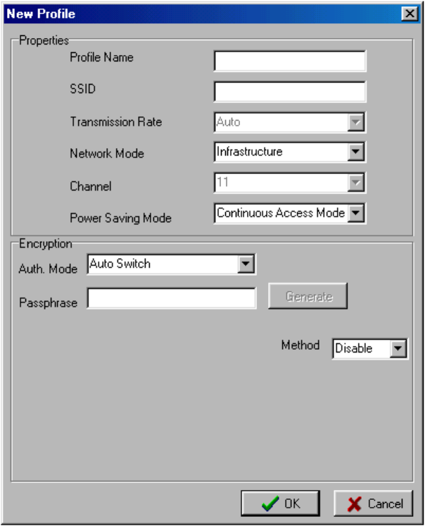
3. In the
Connection Profiles section, choose New.
The New Profile dialog box will appear.
Figure 16. The New Profile dialog box
4. Decide on a name for the profile and type it in.
The name can be any length. It must not contain spaces.
5. Go to the SSID control (by clicking it or pressing Tab) and type in the SSID.
21
If the network is in infrastructure mode and WEP is enabled, skip the next two steps and
go directly to step 8.
If the network is in infrastructure mode and WEP is disabled, skip the next three steps
and go directly to step 9.
6. For an ad-hoc network, adjust the Network Mode control.
The default setting of this control is Infrastructure. Open the list and select 802.11
Ad-hoc or High-speed Ad-hoc. (Use high-speed ad-hoc mode only for links to devices
from the same product family as your adapter.)
7. For an ad-hoc network, check the setting of the Channel control.
The default setting is 11. If the network uses another channel, open the list and select the
correct setting.
8. For a network on which WEP is enabled, provide WEP settings.
Open the Method control and select the correct key length (64, 128, or 256 bits; select 64
bits if the length you were told to use is 40 bits). Boxes for typing in a key or keys will
appear.
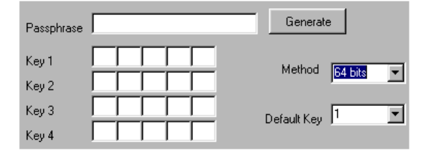
Figure 17. 64-bit WEP key input boxes and controls
Create a key or keys by the hex input or passphrase method. If you have been given a
textual key that is not a passphrase, consult appendix A and type the values
corresponding to the characters of the key into the key input boxes. If you have been
given a passphrase, type it into the Passphrase input box and choose Generate.
64-bit WEP encryption lets you create four keys and switch among them. The “default
key” is the key currently in use on the network. Make sure the Default Key control, if it
appears, is set to the right key.
9. Choose
OK.
You will be returned to the Settings panel. The name of the new profile, the SSID of the
network it is for, and WEP status will appear in the Connection Profiles section.
10. Select the new profile and choose Apply.
Instead of clicking the profile and then clicking Apply, you can double-click the profile.
You will be asked for confirmation. Choose Yes and you will be connected.
22
7 Utility Command Reference
This chapter explains all the controls in the Wireless Adapter Utility’s Settings panel and profile
editor. (The profile editor is the dialog box that appears when you choose New or Details in the
Connection Profiles section of the Settings panel. It is illustrated in figure 16.)
7.1 Settings Panel
The Settings panel displays information about any wireless networks you are within range of,
and any connection profiles you have created. It contains a Site Survey section and a
Connection Profiles section.
7.1.1 Site Survey Section
The Site Survey section shows the following information about any wireless networks you are
within range of:
SSID
The SSID is a name, usually assigned by the network installer or operator, that is shared
by all members of the network. To join any wireless network, you must set your machine
to use that network’s SSID.
BSSID
The BSSID is an automatically assigned numeric identifier for the network. On an
infrastructure network, it is usually the medium access control (MAC) address of the
access point (AP); on an ad-hoc network, it is usually the MAC address of one of the
members. BSSIDs are shown in hexadecimal (base 16) notation.
WEP
WEP stands for Wired Equivalent Privacy, an encryption method that can enhance
network security. WEP can be enabled or disabled. If it is enabled, you must enable it
with the correct settings on your machine to join the network.
Network Mode
The network mode can be infrastructure, where all wireless stations communicate
through an access point (AP), or ad-hoc, where wireless stations communicate directly
with each other. You must set your machine to the same mode as any wireless network
you wish to join.
Channel
A channel is one of 14 groups of adjacent frequencies in the band used for wireless
networking. Not all channels are available in all countries. A station in infrastructure
mode automatically finds the channel used by any access point (AP) it is within range of.
In ad-hoc mode, all stations must be set manually to use the same channel.
The Site Survey section offers the following command functions:
23
• To change the order in which site survey results are displayed, click a column heading.
For example, you can click the WEP column heading to have all networks where WEP is
disabled listed before all networks where WEP is enabled.
• To see all of an SSID that exceeds the width of the SSID column, place the pointer on
that SSID.
Continuation dots show when an SSID is too long for the SSID column. Sometimes you
might have to click the SSID. You can also widen the SSID column by dragging the
BSSID column’s left edge to the right.
• To search again for wireless networks in your vicinity, choose the Search button.
The utility will “listen” for five seconds and then display the results.
7.1.2 Connection Profiles Section
The Connection Profiles section shows information about profiles you have created. A
connection profile contains all the settings you need to connect to a particular wireless network.
You can have profiles for any number of wireless networks.
In addition to each profile’s name, this section shows the network SSID and basic WEP setting
(enabled or disabled). Profiles are initially shown in the order in which they were created.
• To change the order in which profiles are displayed, click a column heading.
For example, you can click the SSID column heading to have profiles listed according to
the alphabetical order of their SSIDs.
• To see all of a profile name or SSID that exceeds the width of the column it is in, place
the pointer on the truncated text.
Continuation dots show when text is too long for the column it is in. Sometimes you
might have to click the text. You can also widen a column by dragging the next column’s
left edge to the right.
• To select a profile for examination, editing, activation, or removal, click anywhere on its
line in the listing.
Double-clicking a profile is the same as selecting it and choosing Apply. To select
multiple profiles for removal, use conventional Microsoft Windows techniques: Ctrl-click
to add an individual profile to the selection, Shift-click to specify the last profile in a
contiguous range. (Ctrl-click will also de-select a selected profile.)
The buttons at the bottom of the Connection Profiles section let you examine, edit, create,
activate, and delete profiles.
Details
To examine or edit a profile, select it in the listing and choose Details. The profile editor
will appear (see section 7.2, “The Profile Editor,” below).
24
New
To create a new profile, choose New at any time. The profile editor will appear (see
section 7.2, “The Profile Editor,” below).
Apply
To use a profile to join a wireless network, select the profile and choose Apply. Double-
clicking a profile has the same effect. You will be asked for confirmation. When you
confirm the command, the utility will put all the settings in the profile into effect and
attempt to join the network.
When a connection attempt is successful, the utility icon in the system tray (also known
as the notification area) shows a green screen and radio waves. The screen of the icon in
the top left corner of the utility’s main window also turns green (both icons show red
screens when you are not connected).
Remove
To delete a profile or profiles, select the profile(s) and choose Remove. You will be
asked for confirmation. When you confirm the command, the profile(s) will immediately
be permanently deleted.
7.2 The Profile Editor
The profile editor is the dialog box that appears when you choose Details or New in the utility’s
Settings panel. It contains all the controls you need to create settings for a wireless network
connection. Each of these controls is explained in a section of its own below.
7.2.1 Profile Name
The Profile Name control is a text input box for giving the profile a name. Each profile must
have a unique name. A profile name can be any length, but it cannot contain spaces. The case of
any letters you type is preserved. When you are editing an existing profile, the name appears on a
gray background here and cannot be edited.
7.2.2 SSID
The SSID control is a text input box for typing the target network’s Service Set Identifier, also
known as the (wireless) network name (or ID), (wireless) domain name (or ID), or Extended
Service Set Identifier (ESSID). All devices on a wireless network must use the same SSID. When
you are within range of a wireless network, you can learn the SSID from the Settings panel’s
Site Survey section (if it is unusually long, you might have to click it there to see all of it). Be
sure to type it in correctly here.
7.2.3 Transmission Rate
The Transmission Rate control is a drop-down list box for selecting a communication speed
setting. The default setting is Auto, that is, automatic speed detection and adjustment. Auto is the
only setting allowed on an infrastructure network or a high-speed ad-hoc network. When the
25
setting of the Transmission Rate control is fixed because of the Network Mode setting, it is
shown in gray characters and the control is disabled.
When the Network Mode control is set to 802.11 Ad-hoc, the Transmission Rate control offers
five settings: Auto, 1 Mbps, 2 Mbps, 5.5 Mbps, and 11 Mbps.
Using a fixed, high speed throughout a network can improve security by reducing the effective
range. Fixed, low speeds may be necessary for interoperation with some pre-802.11b devices.
The Auto setting lets the adapter adjust communication speed according to signal quality; this
setting thus offers the best combination of throughput, range, and resistance to interference.
7.2.4 Network Mode
The Network Mode control is a drop-down list that offers three settings: 802.11 Ad-hoc,
Infrastructure, and High Speed Ad-hoc. You can learn from the Settings panel’s Site Survey
section if a network is in ad-hoc or infrastructure mode; the network installer or operator can tell
you if an ad-hoc network is high-speed (22 Mpbs). You must choose the setting that agrees with
the actual operating mode of the network. High-speed ad-hoc mode can only be used by devices
in the same product family as your adapter.
7.2.5 Channel
Depending on which part of the world you are in, there can be up to 14 “channels” in the radio
frequency band used for wireless networking (2.4 to 2.4835 GHz in most countries). A channel
consists of 23 exact frequencies spaced 1 MHz apart for a total spread of 22 MHz. Such spreading
is required by regulatory agencies to reduce interference among devices operating in this band.
On an infrastructure network, each access point (AP) is set to use a fixed channel, and stations
automatically detect the channel used by the AP that provides the best signal quality. The
Channel control is therefore disabled when the Network Mode control is set to Infrastructure.
An ad-hoc network operates on a fixed channel that will be shown in the Settings panel’s Site
Survey section. To join a given ad-hoc network, you must select the correct channel from the
Channel control’s drop-down list. The settings offered in the list depend on the regulations of the
country in which the adapter was purchased.
APs with overlapping coverage areas, or different ad-hoc networks operating in the same area,
should use channel settings that are at least four, and preferably five channels apart (for example,
1, 6, and 11) to avoid interference and obtain the best possible performance.
7.2.6 Power Saving Mode
The Power Saving Mode control is a drop-down list that offers three settings: Continuous
Access Mode, Maximum Power Save, and Fast Power Save.
In Continuous Access mode, your adapter’s receiver is always on.
Maximum Power Save mode is a “doze” mode in which the adapter turns its receiver off but
“wakes up” at fixed intervals to see if any communications are waiting for it. Before entering this
mode, it tells the AP (or, on an ad-hoc network, the current coordinating station) that it is going to
do so. The AP (or coordinating station) will “buffer” (temporarily store) communications
26
destined for your machine. The adapter stays “awake” only long enough to check for and receive
waiting communications.
Fast Power Save mode is like Maximum Power Save mode except that the adapter checks the
activity level on the network and stays fully “awake” if the activity level is high. When network
traffic falls below a certain level, the adapter returns to “doze” mode.
7.2.7 Auth. Mode
The Auth. Mode (Authentication Mode) control is the first control in the Encryption section of
the profile editor dialog box. It is a drop-down list offering three settings: Open Authentication,
Shared Authentication, and Auto Switch.
The setting of this control is ignored when WEP is disabled.
A machine must request permission to join a wireless network. On some networks where WEP is
enabled, a request to join must be WEP-encrypted; on others, it must not.
In Open Authentication mode, requests to join the network are never WEP-encrypted. In Shared
Authentication mode, all requests to join must be WEP-encrypted. The default setting, Auto
Switch, causes the utility to encrypt its first request and then send a non-encrypted request if the
encrypted request is denied or ignored.
7.2.8 Passphrase
A “passphrase” is a string of characters from which the utility will generate a WEP key or keys.
The Passphrase control is a text input box for typing a passphrase. This box accepts input only
when the Method control (see next section) has been set to 64 bits, 128 bits, or 256 bits
(selecting one of these three settings is the first step in enabling WEP).
A passphrase can be any length, and it can contain any characters that you can type on your
machine, including spaces.
To use the passphrase method of generating WEP keys, (1) make sure the Method control is set
to the right key length, (2) select the Passphrase control, (3) type in a passphrase, and (4) choose
the Generate button.
The passphrase and the generated key or keys are shown on your screen only in the current
profile editor session. If you save the profile and later open it for editing, the Passphrase box
will be blank and the key input boxes will show only asterisks.
All wireless networking products made by the manufacturer of your adapter will generate the
same key or keys from a given passphrase. To use a passphrase-generated key on a product from
another company, you must write down the generated values and type them in one by one in the
configuration software for that product.
7.2.9 Method
The Method control is a drop-down list for selecting a WEP setting. Four settings are offered:
Disable, 64 bits, 128 bits, and 256 bits.
27
(So-called 40-bit WEP encryption is the same as that offered by the 64 bits setting. On all
wireless networking products, only 40 bits of a 64-bit key, and 104 bits of a 128-bit key, are input
by the user.)
The default setting is Disable. Selecting any other setting enables the WEP key input controls
(for example, the Passphrase input box and Generate button). WEP itself is not enabled in the
profile until you complete WEP key input.
Selecting 64, 128, or 256 bits also causes input boxes to appear. These boxes show and accept
only “hex” (hexadecimal, that is, base 16) notation. In hex, the numbers 0 through 9 and the
letters A through F are all considered digits (the letters stand for the values we normally refer to
as ten through fifteen). When typing into one of these boxes you must type two hex digits, or your
input is considered incomplete.
If you select 64 bits, boxes for four WEP keys appear; a Default Key control is also displayed.
The Default Key control is a drop-down list for indicating which of the four keys is currently in
use on the network. The current key must be selected here, or you will not be able to connect.
If you select 128 bits, thirteen boxes for a single key will appear.
The 256 bits setting can only be used on connections to devices in the same product family as
your adapter. Selecting 256 bits causes 29 input boxes to appear.
A WEP key may be supplied to you in the form of a passphrase, a series of values in hex, or a
plain text string that is not a passphrase.
• See the preceding section for instructions on using a passphrase.
• If you are given a key or keys in hex, type the values directly into the hex input boxes.
• A plain text string must be converted into hexadecimal notation for input. Consult the
conversion charts in appendix A, and then type the correct values directly into the hex
input boxes.
28
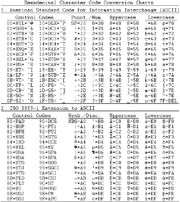
Appendix A: Character Conversion Charts
These charts show both control codes and printable characters. Control codes (including DEL)
have no standard printed representations and are unlikely to appear in plain-text WEP keys; they
are included for completeness only.
Printable characters appear in the punctuation/numbers, symbols/diacritics, uppercase, and
lowercase columns. Each is followed by an equals sign and a numeric value in hexadecimal
notation. Type the value into the appropriate WEP key hex input box. To input the WEP key
Mimsy, for example, you would type 4D, 69, 6D, 73, and 79 into the boxes for the key.
29
Appendix B: Troubleshooting
Problem: Adapter installation appears to have failed.
Solutions:
• Make sure the adapter is firmly seated in the CardBus slot.
• Uninstall and reinstall the adapter. If the problem persists, uninstall the adapter and install
it in another slot. If possible, try the adapter in another computer to see if the problem is
in the adapter or the computer.
• Check to see if there is an IRQ conflict with another device:
1. Open the
Start menu, go to Settings, choose Control Panel, open the System
icon, choose Device Manager, and open the Network adapters entry. If an
exclamation mark [!] appears on the adapter icon, select the icon and choose
Properties.
2. Under
Conflicting device list in the Resources panel of the Properties dialog
box, you will see a device conflict message.
3. Uncheck
Use automatic settings and choose the Change Setting button.
4. Select a new IRQ value. When the message “No conflicts” appears in the
Properties dialog box, close all windows by choosing OK, and then restart the
computer.
Problems: (1) The adapter fails to function. (2) The adapter’s LEDs are both off. (3) The
operating system does not detect the adapter.
Solution: These problems may be caused by unsuccessful installation. If you are sure that the
adapter is firmly seated in a working slot and has not been turned off through the software, we
recommend that you completely uninstall the adapter, the driver, and the utility, and then repeat
the installation procedures described in this manual.
Problem: You cannot join a network that currently appears in the Settings panel’s Site
Survey section.
Solution: Make sure the computer has the same SSID and security settings as the access point or
(in the case of an ad-hoc network) whatever device represents the network in the Site Survey
listing.
• SSID: The SSID is case-sensitive. Every device on a wireless network must use exactly
the same SSID.
• Security: If the Site Survey list shows that WEP is disabled on the network, WEP must
be disabled on your machine. If WEP is enabled on the network, it must be enabled with
the same key length and contents on your machine.
In addition, if WEP is enabled, the Auth. Mode control must be set to either Auto Switch
or the mode used on the network (open authentication or shared authentication).
30
If the network is in ad-hoc mode, in addition to using the correct SSID and security settings, you
must use the channel indicated in the Site Survey section and set the transmission rate to Auto or
the exact fixed speed used on the network.
Remember that high-speed ad-hoc mode and 256-bit WEP encryption can be used only on
connections to devices in the same product line as your adapter.
Select the connection profile for the network, choose Details, edit the profile, choose OK, and
choose Apply to put the new settings into effect.
Problem: An initially good wireless link fails, or the link alternates between good and bad
(the utility icon in the system tray goes from green to red, or constantly alternates between
green and red).
Solutions:
• On an ad-hoc network, the link may go up and down for a short while until the network
adjusts to the addition of a new member. A different BSSID may appear in the
Information panel each time the link comes back. The link should quickly stabilize; try
the solutions below only if the problem persists.
• The computer may be too far from the access point (or the nearest ad-hoc network
member). If possible, move closer. In some cases, changing the orientation of the antenna
(on one device or both) can help.
• There may be interference from a microwave oven, cordless phone, or remote control.
Shut down the interfering device, move it further away, or move away from it. If channel
selection is under your control, setting the access point (or all members of an ad-hoc
network) to use a different channel may solve the problem.
• Objects in the vicinity may be blocking or reflecting the signal. Metallic and other high-
density objects affect radio signals the most, but even a tinted or wet window can reduce
signal quality. Signal reflection, even from a remote object, can cause serious “multipath
distortion” (this also causes “ghosts” on television screens). Try a different location
(sometimes a small shift is all that is needed), or, if possible, move objects that may be
affecting reception.
• Make sure the access point (or ad-hoc network member) is working correctly. Check all
antennas, connectors, and cables.
Problem: A working, nearby access point does not appear in the Site Survey listing.
Solutions:
• Check the range, and check the environment for interference, signal absorption, and
signal reflection (see preceding).
• The access point may be set not to broadcast its SSID. If possible, change the setting;
otherwise, contact your dealer to see if an updated driver is available for the adapter.
31
Appendix C: Technical Support
If you encounter a problem that cannot be solved by following the steps in the troubleshooting
section, call your networking equipment supplier for help. Have the following information ready
before you make the call:
• Full product name and, if possible, firmware version number
• Version numbers of all software products included in the package
• Operating system name and version
• Network type and configuration, and any recent configuration changes
• Actions that led to the situation that prompted the call
• LED status and any on-screen messages seen in connection with the problem
If it appears that a return or exchange will be required, you may be asked to provide the serial
number of the product.
Support personnel may ask you to try to reproduce the problem. They may also ask you to run
some simple tests using diagnostic tools included with the system. Proper preparation on your
part can greatly reduce the amount of time needed to solve the problem.
32
Appendix D: Limited Warranty
Hardware
The manufacturer warrants its products to be free of defects in workmanship and materials, under
normal use and service, for a period of 12 months from the date of purchase from the
manufacturer or its authorized reseller, and for the period of time specified in the documentation
supplied with each product.
Should a product fail to be in good working order during the applicable warranty period, the
manufacturer will, at its option and expense, repair or replace it, or deliver to the purchaser an
equivalent product or part at no additional charge except as set forth below. Repair parts and
replacement products are furnished on an exchange basis and will be either reconditioned or new.
All replaced products and parts will become the property of the manufacturer. Any replaced or
repaired product or part has a warranty of ninety (90) days or the remainder of the initial warranty
period, whichever is longer.
The manufacturer shall not be liable under this warranty if its testing and examination disclose
that the alleged defect in the product does not exist or was caused by the purchaser’s or any third
party’s misuse, neglect, improper installation or testing, unauthorized attempt at repair or
modification, or any other cause beyond the range of the intended use, or by accident, fire,
lightning, or other hazard.
Software
Software and documentation materials are supplied “as is,” without warranty as to their
performance, merchantability, or fitness for any particular purpose. However, the media
containing the software is covered by a 90-day warranty that protects the purchaser against failure
within that period.
Limited Warranty Service Procedure
Any product (1) received in error, (2) received in a defective or non-functioning condition, or (3)
exhibiting a defect under normal working conditions, can be returned to the manufacturer by
following these steps:
1. Prepare the following in printed or electronic form:
• Dated proof of purchase
• Product model number and quantity
• Product serial number
• Precise reason for return
• Your name, address, email address, phone number, and fax number
2. Inform the distributor or retailer.
3. Ship the product back to the distributor/retailer with freight charges prepaid. The
purchaser must pay the cost of shipping from the distributor/retailer to the manufacturer.
Any package sent C.O.D. (Cash On Delivery) will be refused.
33
Charges: Usually, RMA (Returned Material Authorization) items will be returned to the
purchaser via airmail, prepaid by the manufacturer. If any item is returned by another carrier, the
purchaser will pay the difference. A return freight and handling fee will be charged to the
purchaser if the manufacturer determines that the product is not defective or that the damage was
caused by the user.
Warning
The manufacturer is not responsible for the integrity of any data on storage equipment (hard
drives, tape drives, floppy diskettes, etc.). We strongly recommend that our customers back their
data up before sending such equipment in for diagnosis or repair.
Service After Warranty Period
After the warranty period expires, all products can be repaired for a reasonable service charge.
The shipping charges to and from the manufacturer’s facility will be borne by the purchaser.
Return for Credit
In the case of a DOA item (an item that is “dead on arrival”) or a shipping error, a return for
credit will automatically be applied to the purchaser’s account, unless otherwise requested.
Limitation of Liability
All expressed and implied warranties of a product’s merchantability, or of its fitness for a
particular purpose, are limited in duration to the applicable period as set forth in this limited
warranty, and no warranty will be considered valid after its expiration date.
If this product does not function as warranted, your sole remedy shall be repair or replacement as
provided for above. In no case shall the manufacturer be liable for any incidental, consequential,
special, or indirect damages resulting from loss of data, loss of profits, or loss of use, even if the
manufacturer or its authorized distributor/dealer has been advised of the possibility of such
damages, or for any claim by any other party.

34
Appendix E: Specifications
Standards compliance IEEE 802.11b, PCMCIA CardBus (Type II)
Regulatory compliance
USA: FCC Part 15 Class B
EU: ETS 300.328, ETS 300.826, CE Mark
Japan: ARIB STD-T66
Frequency band 2400.0 to 2497.0 MHz (Japan)
2400.0 to 2483.5 MHz (North America and Europe)
2445.0 to 2475.0 MHz (Spain)
2446.5 to 2483.5 MHz (France)
Transmitter power 15 dBm (typical)
Receiver sensitivity* 11 Mbps: -82 dBm (typical)
22 Mbps: -78 dBm (typical)
* Minimum receiver input power level at which a frame error ratio (FER) of less than 8% can be maintained, given a
packet length of 1024 bytes and conditions of 20° to 30° C.
Input power DC 3.3V ±5%
Power consumption 550 mA/3.3V (transmitting), 350 mA/3.3V (receiving)
Data rates 11, 5.5, 2, and 1 Mbps with auto fallback
Special user-selectable 22 Mbps option
RF spreading scheme Direct-sequence spread-spectrum (DSSS)
Encoding and modulation
methods
1 Mbps: Barker sequence + BPSK
2 Mbps: Barker sequence + QPSK
5.5 and 11 Mbps: CCK/PBCC
22 Mbps: PBCC
Security 64- and 128-bit Wired Equivalent Privacy (WEP) encryption
Special user-selectable 256-bit WEP option
Antenna Internal printed diversity type
LED indicators Two: power on/off (green) and wireless activity (orange)
Dimensions (L × W × H) 118 × 54 × 9 mm
Environmental requirements
Operating temperature: 0° to 50° C
Storage temperature: -30° to 70° C
Operating
humidity: Tested to RH 85% at 40° C (104° F) for 48
hours
Accompanying software Drivers for Microsoft Windows 98/ME (NDIS 5.0), 2000 (NDIS
5.0), and XP (NDIS 5.1); configuration utility with connection
profile management for multiple networks

35
Appendix F: Channels and Regulations
The following table lists the IEEE 802.11b transmission channels and provides important notes
on regulations regarding channel use.
Channel Start, Center, and
End Frequencies (MHz) Non-overlapped
Channels Notes
1 2401 2412 2423 6-14 1
2 2406 2417 2428 7-14 1
3 2411 2422 2433 8-14 1
4 2416 2427 2438 9-14 1
5 2421 2432 2443 10-14 1
6 2426 2437 2448 1, 11-14 1
7 2431 2442 2453 1, 2, 12-14 1
8 2436 2447 2458 1-3, 13, 14 1
9 2441 2452 2463 1-4, 14 1
10 2446 2457 2468 1-5, 14
11 2451 2462 2473 1-6
12 2456 2467 2478 1-7 2
13 2461 2472 2483 1-8 2
14 2473 2484 2495 1-10 3
1. Not used where the regulations of Spain or France are in effect.
2. Not used where the regulations of Spain or North America are in effect.
Notes:
3. Used only where the regulations of Japan are in effect.
An illustration of IEEE 802.11b channel distribution and overlap appears below.
Wireless networking channels in the 2.4-GHz frequency band