National Datacomm 3050S01 802.11g+ MiniPCI Module User Manual NWH1050 User s Guide
National Datacomm Corporation 802.11g+ MiniPCI Module NWH1050 User s Guide
UserManual.wiki
>
National Datacomm
>
3050S01 User Manual
User Manual
Navigation menu
Upload a User Manual
Namespaces
Wiki Guide
HTML
PDF
Info
Views
User Manual
Discussion / Help
Navigation
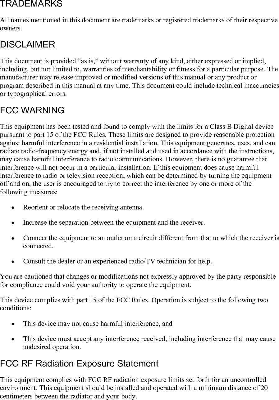
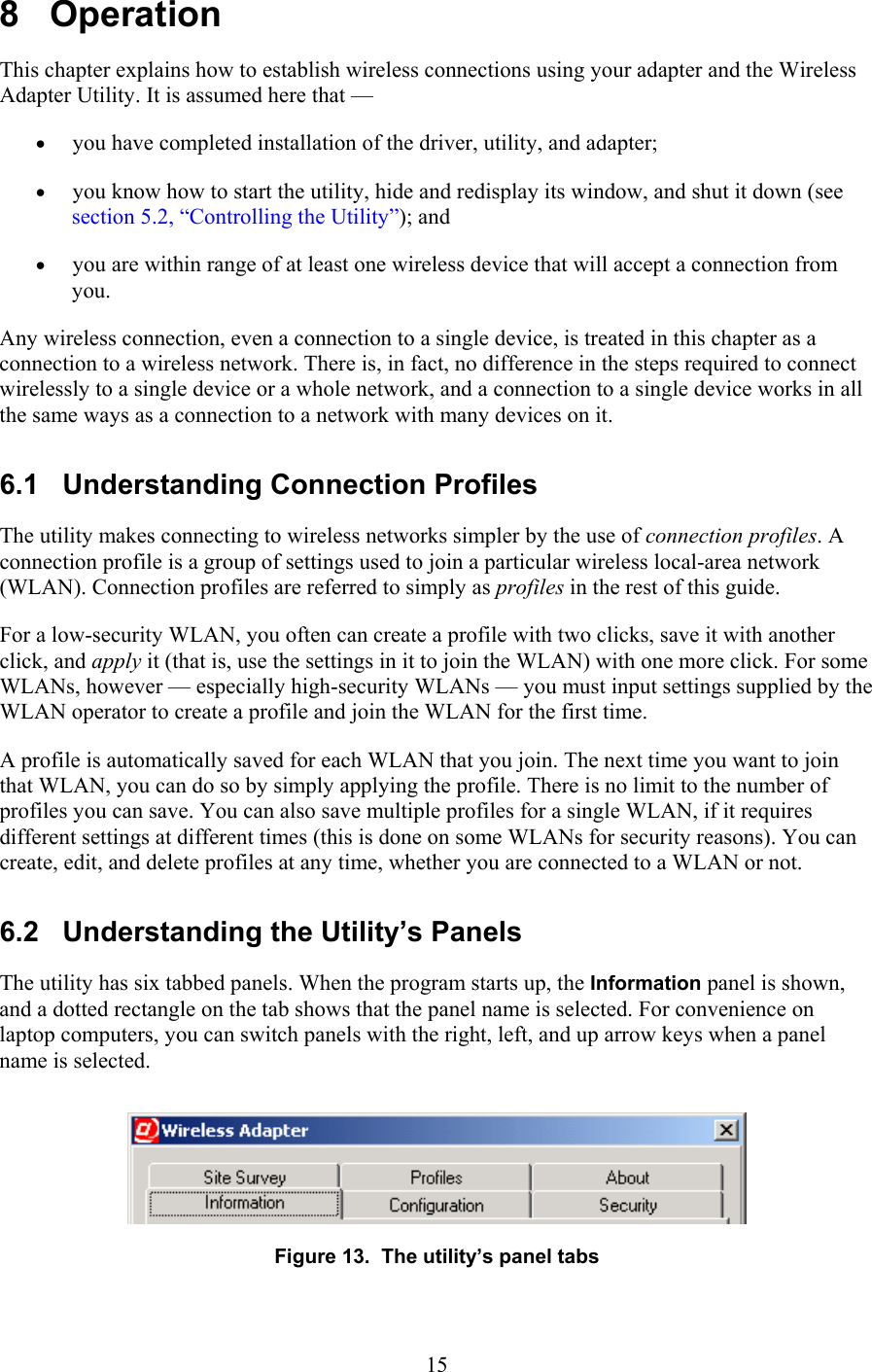
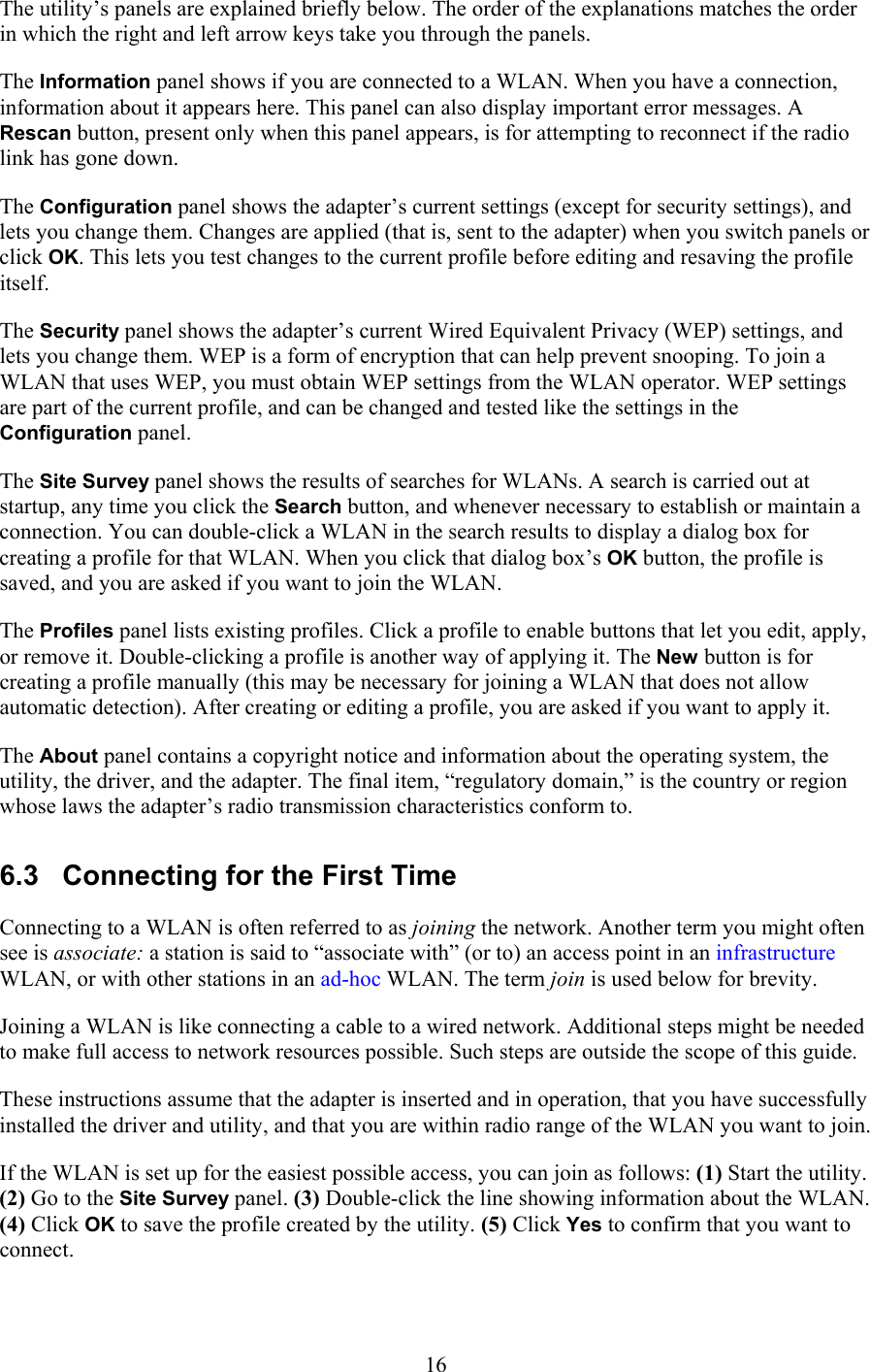
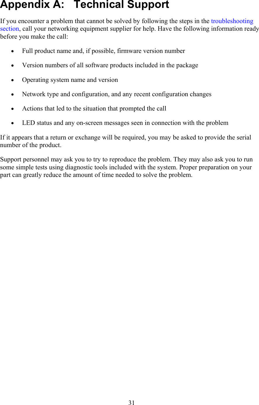
![This process is described in greater detail below. 1. Start up the Wireless Adapter Utility. The utility’s Information panel will appear. In most cases, the first time you run the utility, this panel will show that you have not joined a WLAN. If the WLAN you want to join allows automatic detection, the utility can create a profile containing all or most of the settings required for joining. You will need little or no information from the network operator. If the WLAN does not allow automatic detection, you will have to obtain configuration and security information from the operator. Then, to create a profile and join the WLAN, go to the Profiles panel, click New, input all the information, and click OK. It is assumed here that the WLAN allows automatic detection. If it does, information about it will appear on your screen in the next step. 2. Go to the Site Survey panel. Note the information shown in the SSID and WEP columns. An SSID (Service Set Identifier) is a name assigned to a WLAN by the operator. If more than one WLAN is listed, the SSIDs should help you identify the one you want to join. (The SSID is sometimes called the network [or domain] name [or ID].) WEP is Wired Equivalent Privacy, a means of encrypting digital radio transmissions to prevent snooping. Look to see if WEP is disabled or enabled on the WLAN; this affects what you must do in this step and the next. • If WEP is disabled, the utility can create a profile containing all the settings required for joining the WLAN. Go straight to step 3. • If WEP is enabled, encryption is used for security on the WLAN, and you will need to know (1) the encryption method (64-, 128-, or 256-bit WEP), (2) the format of the “key” or keys (“hex” or “ASCII” — that is, numeric or textual), (3) the key or keys, and in some cases, (4) the “authentication mode” (“open” or “shared”). The encryption method is sometimes called the “key length,” and 64-bit WEP is sometimes called “40-bit WEP.” If you have received a key or keys but are not sure of the method and format, see the additional explanations in step 3. 3. Double-click the WLAN that you want to join. A window titled New Profile will appear. It will show a suggested name for the profile and, in a panel titled Configuration, adapter settings that the utility has determined are suitable for joining the WLAN. The name and most of the settings should be left unchanged. If you need to conserve battery power on a laptop computer, you can set the Power Saving Mode control to Maximum Power Save. This will make the adapter turn its receiver off and on periodically when you are connected to this WLAN. As a result, the connection might sometimes seem slower than usual. 17](https://usermanual.wiki/National-Datacomm/3050S01/User-Guide-399821-Page-21.png)
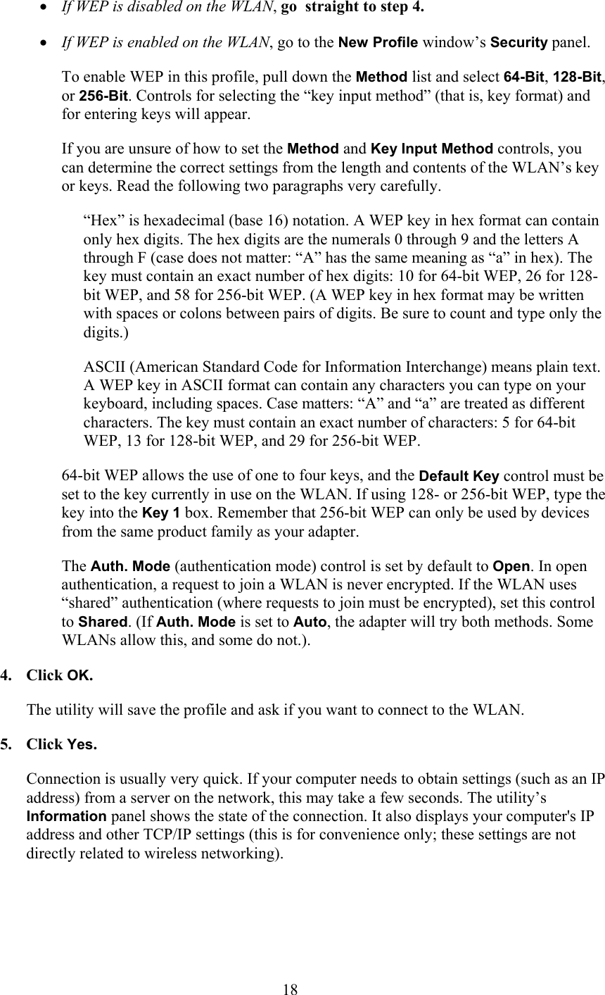
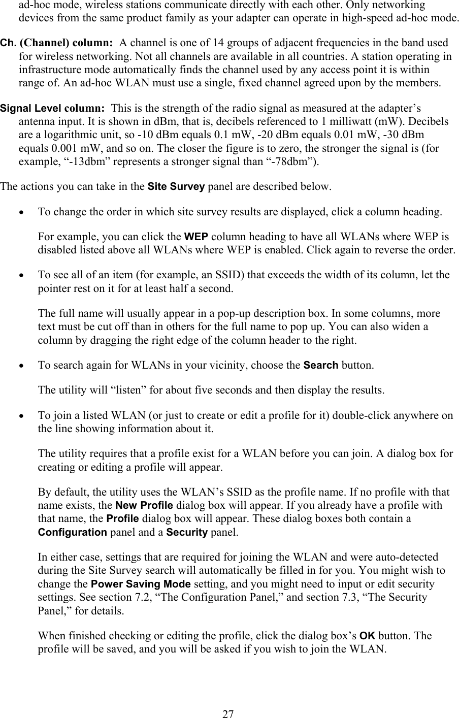
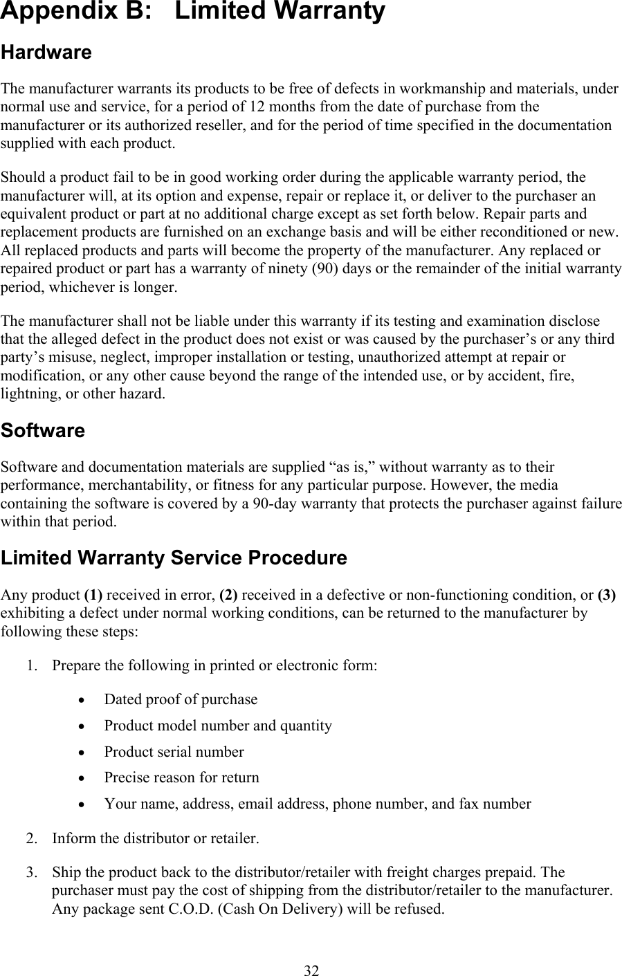
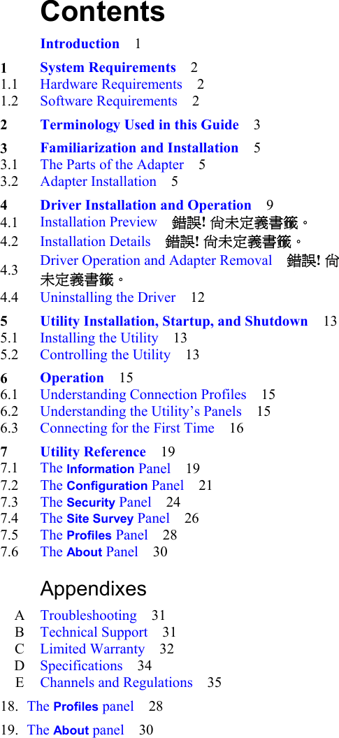
![7.3 The Security Panel The descriptions in this section apply to the Security panels in the main window, the New Profile dialog box, and the Profile dialog box. These panels all contain the same controls. Use the main window’s Security panel (shown below, without its initially blank lower part) to view the adapter’s current security settings, and to make experimental or temporary changes. Figure 16. The main window’s Security panel When you want to save security settings, you must (1) access the New Profile or Profile dialog box, either from the Site Survey panel (by double-clicking a listed WLAN) or from the Profiles panel (by clicking New, or by selecting a profile and clicking Edit), and then (2) click the New Profile or Profile dialog box’s Security tab. When a WLAN is auto-detected, the adapter can detect only whether security (in the form of Wired Equivalent Privacy [WEP] encryption) is on or off (“enabled” or “disabled”). Where security is on (that is, WEP is enabled), you must obtain WEP settings from the WLAN operator and input them in the Security panel to be able to join the WLAN. Method control: The Method control is a drop-down list for selecting a WEP setting. Four settings are offered: Disabled, 64-Bit, 128-Bit, and 256-Bit. (So-called 40-bit WEP encryption is the same as that offered by the 64-Bit setting. On all wireless networking products, only 40 bits of a 64-bit key, and 104 bits of a 128-bit key, are input by the user.) The default setting is Disabled. Selecting any other setting enables the Default Key control and causes the Key Input Method, Key 1, Key 2, Key 3, and Key 4 controls to appear. Default Key control: On a WLAN that uses 64-bit WEP, each device can store one to four WEP keys. The WLAN can then switch among these keys from time to time for better security. The “default key” is the key currently in use on the WLAN. This control lets you switch quickly, without having to input the current key each time it is switched. The default setting is Key 1. Auth. Mode control: “Authentication” is the process of determining whether a requesting station should be permitted to join the WLAN. A station authenticates itself by using the correct SSID in its request to join. If WEP is enabled, the WLAN may require that requests to join be 24](https://usermanual.wiki/National-Datacomm/3050S01/User-Guide-399821-Page-28.png)
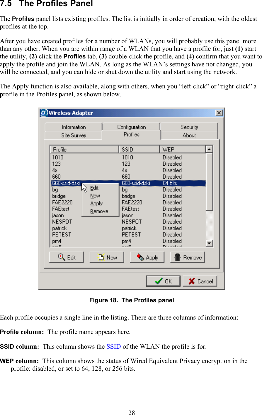
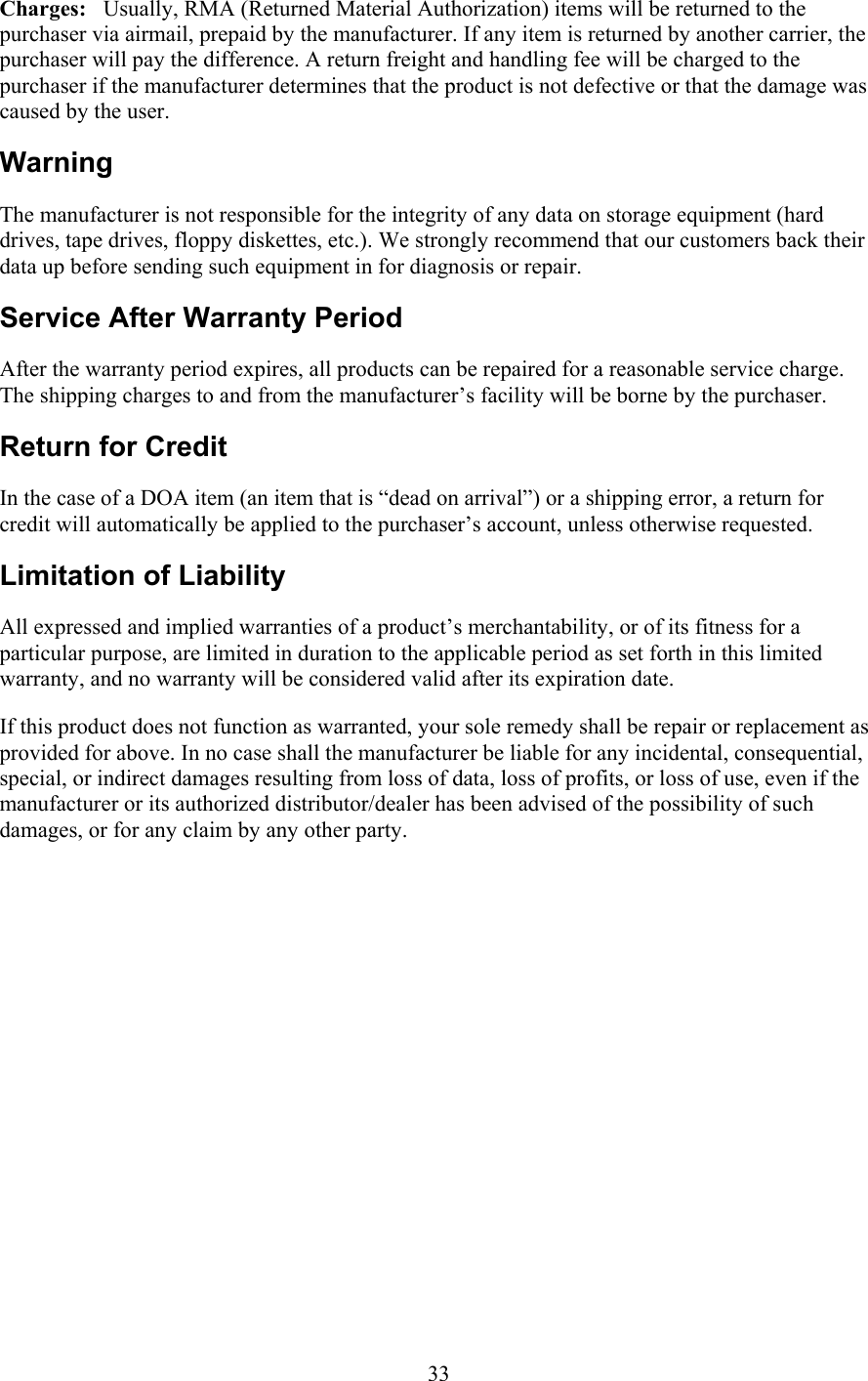
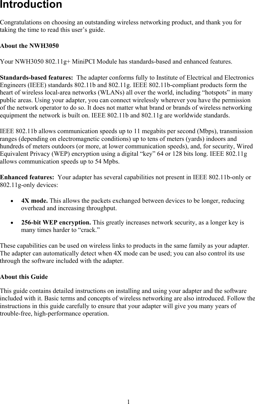
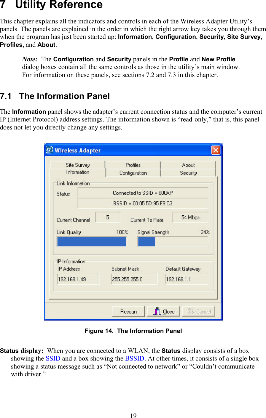
![7.4 The Site Survey Panel The Site Survey panel shows the results of searches for WLANs. A search is carried out automatically when the utility starts up and whenever necessary to establish or maintain a connection. You can start a search manually by clicking the Search button. Figure 17. The Site Survey panel Each WLAN found in a search appears on a line of its own in the Site Survey listing. The information shown is divided into the following columns: SSID column: The SSID is a name, usually assigned by the network operator, that is shared by all members of the WLAN. It is sometimes called the network (or domain) name (or ID). BSSID column: The BSSID is an automatically assigned numeric identifier. On an infrastructure WLAN, the BSSID shown is usually the medium access control (MAC) address of the closest access point; on an ad-hoc network, it is usually the MAC address of one of the members. BSSIDs are shown in hexadecimal (base 16) notation, with a colon [:] added between each pair of digits to aid readability. WEP column: WEP stands for Wired Equivalent Privacy, an encryption method that can enhance network security. WEP can be enabled or disabled. If it is enabled, you must enable it with the correct settings on your machine to join the network. Network Mode column: The network mode can be infrastructure, 802.11 ad-hoc, or high-speed ad-hoc. In infrastructure mode, all wireless stations communicate through an access point. In 26](https://usermanual.wiki/National-Datacomm/3050S01/User-Guide-399821-Page-30.png)